EP2495553A2 - Portable boroscope for inspecting turbomachine blades - Google Patents
Portable boroscope for inspecting turbomachine blades Download PDFInfo
- Publication number
- EP2495553A2 EP2495553A2 EP12157774A EP12157774A EP2495553A2 EP 2495553 A2 EP2495553 A2 EP 2495553A2 EP 12157774 A EP12157774 A EP 12157774A EP 12157774 A EP12157774 A EP 12157774A EP 2495553 A2 EP2495553 A2 EP 2495553A2
- Authority
- EP
- European Patent Office
- Prior art keywords
- boroscope
- battery
- portable
- protective case
- probe
- Prior art date
- Legal status (The legal status is an assumption and is not a legal conclusion. Google has not performed a legal analysis and makes no representation as to the accuracy of the status listed.)
- Ceased
Links
Images



Classifications
-
- G—PHYSICS
- G01—MEASURING; TESTING
- G01N—INVESTIGATING OR ANALYSING MATERIALS BY DETERMINING THEIR CHEMICAL OR PHYSICAL PROPERTIES
- G01N21/00—Investigating or analysing materials by the use of optical means, i.e. using sub-millimetre waves, infrared, visible or ultraviolet light
- G01N21/84—Systems specially adapted for particular applications
- G01N21/88—Investigating the presence of flaws or contamination
- G01N21/95—Investigating the presence of flaws or contamination characterised by the material or shape of the object to be examined
- G01N21/954—Inspecting the inner surface of hollow bodies, e.g. bores
-
- F—MECHANICAL ENGINEERING; LIGHTING; HEATING; WEAPONS; BLASTING
- F01—MACHINES OR ENGINES IN GENERAL; ENGINE PLANTS IN GENERAL; STEAM ENGINES
- F01D—NON-POSITIVE DISPLACEMENT MACHINES OR ENGINES, e.g. STEAM TURBINES
- F01D21/00—Shutting-down of machines or engines, e.g. in emergency; Regulating, controlling, or safety means not otherwise provided for
- F01D21/003—Arrangements for testing or measuring
-
- F—MECHANICAL ENGINEERING; LIGHTING; HEATING; WEAPONS; BLASTING
- F01—MACHINES OR ENGINES IN GENERAL; ENGINE PLANTS IN GENERAL; STEAM ENGINES
- F01D—NON-POSITIVE DISPLACEMENT MACHINES OR ENGINES, e.g. STEAM TURBINES
- F01D5/00—Blades; Blade-carrying members; Heating, heat-insulating, cooling or antivibration means on the blades or the members
- F01D5/005—Repairing methods or devices
-
- G—PHYSICS
- G02—OPTICS
- G02B—OPTICAL ELEMENTS, SYSTEMS OR APPARATUS
- G02B23/00—Telescopes, e.g. binoculars; Periscopes; Instruments for viewing the inside of hollow bodies; Viewfinders; Optical aiming or sighting devices
- G02B23/24—Instruments or systems for viewing the inside of hollow bodies, e.g. fibrescopes
- G02B23/2476—Non-optical details, e.g. housings, mountings, supports
- G02B23/2492—Arrangements for use in a hostile environment, e.g. a very hot, cold or radioactive environment
-
- F—MECHANICAL ENGINEERING; LIGHTING; HEATING; WEAPONS; BLASTING
- F05—INDEXING SCHEMES RELATING TO ENGINES OR PUMPS IN VARIOUS SUBCLASSES OF CLASSES F01-F04
- F05D—INDEXING SCHEME FOR ASPECTS RELATING TO NON-POSITIVE-DISPLACEMENT MACHINES OR ENGINES, GAS-TURBINES OR JET-PROPULSION PLANTS
- F05D2230/00—Manufacture
- F05D2230/80—Repairing, retrofitting or upgrading methods
Definitions
- This disclosure relates generally to inspecting turbomachine components and, more particularly, to inspecting turbomachine blades using a portable boroscope.
- Turbomachines include various blades. Some blades rotate during operation. Other blades remain stationary. The blades may operate in high temperatures environments. Exposure to sufficiently high temperatures can damage the blades as is known. Accordingly, many blades include internal passages that communicate a flow of air through the blades. The flow of air removes thermal energy from the blades to cool the blades.
- Blades become worn over time, and some blades may become damaged. Operating the turbomachine with worn or damaged blades can reduce the efficiency of the turbomachine. Replacement blades are expensive to manufacture. Thus, it is often desirable to refurbish worn or damaged blades, rather than replacing worm or damaged blades with new blades.
- the internal passages in the blades are periodically inspected during a refurbishing procedure.
- the inspection identifies blockages, internal damage, etc.
- the internal passages of newly manufactured blades typically undergo a similar inspection.
- Technicians may use bench-based boroscopes to inspect the internal passages. Inspecting the blades using bench-based boroscopes is time consuming as the blades must be moved to the location of the bench-based boroscope.
- An example portable boroscope assembly for inspecting passages within a turbomachine blade includes a boroscope probe and a display screen.
- the display screen is configured to show images of areas inspected by the boroscope probe.
- a battery powers the display screen.
- a protective case holds at least the display screen and the battery. The protective case defines an aperture. The display screen is viewable through the aperture.
- Another example portable boroscope assembly for inspecting passages within a turbomachine blade includes a camera and a probe tip operatively coupled with the camera.
- the assembly also includes a display and a light that are operatively coupled to the probe tip.
- a battery powers the camera, the display, and the light.
- the protective case holds at least the display and the battery.
- An example method of inspecting a turbomachine blade using a boroscope inspection assembly includes powering a boroscope inspection device using a battery and inspecting a fluid passage established within a turbomachine blade using the boroscope inspection device.
- an example turbomachine such as a gas turbine engine 10 is circumferentially disposed about an axis 12.
- the gas turbine engine 10 includes a fan 14, a low pressure compressor section 16, a high pressure compressor section 18, a combustion section 20, a high pressure turbine section 22, and a low pressure turbine section 24.
- Other example turbomachines may include more or fewer sections.
- the high pressure compressor section 18 includes a rotor 32.
- the low pressure compressor section 16 includes a rotor 33.
- the rotors 32 and 33 are configured to rotate about the axis 12.
- the example rotors 32 and 33 include alternating rows of rotating airfoils or rotating blades 34 and static airfoils or static blades 36.
- the static blades 36 may also be referred to as static vanes.
- the high pressure turbine section 22 includes a rotor 26.
- the low pressure turbine section 24 includes a rotor 27.
- the rotors 26 and 27 are configured to rotate about the axis 12 in response to expansion to drive the high pressure compressor section 18 and the low pressure compressor section 16.
- the example rotors 26 and 27 include rotating arrays of blades 28, for example.
- the example turbomachine described in this disclosure is not limited to the two spool gas turbine architecture described, however, and may be used in other architectures, such as the single spool axial design, a three spool axial design, and still other architectures. That is, there are various types of gas turbine engines, and other turbomachines, that can benefit from the examples disclosed herein.
- an example blade 50 from the Figure 1 turbomachine extends axially from a base 52 to a tip 54.
- the blade 50 includes a radially extending airfoil 56.
- the blade 50 is one of the rotating blades from the rotor 32. In other examples, the blade 50 is a stationary blade, or a blade from the one of the turbine sections 26 and 27.
- Example blade 50 has been used within the engine 10 and is being refurbished for the purpose of reinstallation into the engine 10.
- Example refurbishing processes may include acid stripping blades, reapplying coatings to blades, adding new tips to blades, adding additional material to worn areas of blades..
- the example blade 50 establishes a plurality of internal passages 58.
- apertures 60 established in the base 52 represent the starting point for internal passages 58
- cooling holes 62 represent the termination point.
- a cooling airflow moves from an air supply 61 into the internal passages 58 through the apertures 60.
- the cooling airflow exits the internal passages 58 through the cooling holes 62.
- the cooling airflow moving through the internal passages 58 of the blade 50 cools the blade 50. Also, air exiting the internal passages 58 through the cooling holes 62 may cool the blade 50 by film cooling, for example.
- the internal passages 58 are a type of fluid communication paths.
- an example boroscope inspection device 66 is used to inspect the internal passages 58 of the blade 50.
- the inspection device 66 may reveal internal passages 58 that are blocked, for example. Such blockages prevent a cooling airflow from moving through some portions of the blade 50, which can undesirably result in thermal energy concentrations within the blade 50.
- the inspection device 66 may be used to inspect a blade that is being refurbished or to inspect a newly manufactured blade.
- the example inspection device 66 includes a probe 68 having a probe tip 70.
- a video camera 72 is removably attachable to the probe 68.
- an adapter may be required to attach the video camera 72 and the probe 68.
- the example video camera 72 is operatively linked to a display 74 and a battery 76.
- the display 74 includes a display screen 78 that shows images inspected by the probe 68.
- a person having skill in this art and the benefit of this disclosure would understand how to display the images of the inspected areas on the display screen 78.
- the display screen is a 7 inch (17.78 centimeter) display screen in this example. The images show a blockage within the internal passages 58.
- the display 74 and the video camera 72 are both powered exclusively by the battery 76.
- the example battery 76 is a 12 volt, 5.2 amp rechargeable battery. The life of the example battery 76 is about 3.0 hours.
- a recharging station may be used to recharge the battery 76 when the inspection device 66 is not in use.
- the example inspection device 66 also includes a light 80 that is removably attachable to the probe 68.
- the light 80 is used to illuminate areas inspected by the probe 68, such as the internal passages 58.
- a wriststrap 81 is attached to the light 80 to help an inspector secure the probe 68 and the light 80 during an inspection procedure.
- the example inspection device 66 includes a protective case 82 that holds the battery 76, the display 74, and the video camera 72. During an inspection procedure, the video camera 72 may be removed from the protective case 82 or may stay within the protective case 82. The probe 68 typically remains outside the protective case 82, along with the light 80, regardless the location of the video camera 72.
- the example protective case includes a lid 84 that establishes an aperture 86.
- the aperture 86 allows a user, such as the inspector, to view at least a portion of the display screen 78 when the lid 84 is closed.
- a clear protective cover 87 is used in this example to protect against damage to the screen 78 through the aperture 86, which is about 1.5 inches (3.81 cm) in this example.
- the example protective case 82 is 14 inches (45.56 cm) long, 10 inches (25.4 cm) wide, and 3.5 inches (8.89 cm) tall.
- the lid 84 of the protective case 82 is closed when the lid 84 is placed over a base 88 of the protective case 82.
- the lid 84 is hinged to the base 88 in this example.
- Figure 4 shows the protective case 82 in an open position
- Figure 5 shows the protective case 82 in a closed position.
- an inspection may be carried out with the protective case 82 in a closed position.
- An on/off switch 90 is secured within the lid 84 of the example protective case 82. An inspector actuates the on/off switch 90 to selectively supply power to the video camera 72 and the display 74 from the battery 76.
- the protective case 82 also includes a charging location (not shown) for the battery 76 so that the battery 76 may be recharged at the 110V recharging station without requiring the operator to open the protective case 82. Wiring connects the various components of the inspection device 66 where needed.
- the inspector may transport the inspection device 66 to the blade 50 using a carrying handle 83 established within the protective case 82.
- the probe tip 70 is then inserted through the aperture 60 established within the base 52 of the blade 50.
- the inspector may be required to attach the probe 68 and light 80 to the video camera 72 prior to insertion of the probe tip 70.
- the shape of the probe tip 70 allows the inspector to inspect the full radial length of the internal passages 58 by continuing to insert the probe tip 70 into the aperture 60.
- the probe tip 70 is flexible, which also facilitates inspection.
- the inspection may reveal, for example, foreign material, corrosion, and damage within the internal passages 58.
- the probe tip 70 may be used to inspect internal trip strips in some examples.
- the inspection utilizing the inspection device 66 is coupled with inspections utilizing a magnitoscope, which may improve detection of corrosion.
- Typical blades inspected by the inspection device 66 are between 3 inches (76.2 mm) and 10 inches (254 mm) long.
- the example probe tip 70 is longer than the typical blades to provide the operator with adequate length to manipulate the position of the probe tip 70.
- the inspection device 66 may be used to inspect other areas of the engine 10 requiring a relatively slender probe tip.
- an example probe tip 70 has a length 1 that is between 17-3/8 inches (44.1325 cm) and 29-3/8 inches (74.6125 cm). In one specific example, the probe tip 70 is 25 inches (63.5 cm) with a tolerance of +/- 1/8 inch (3.175 cm). The diameter d of the example probe tip 70 is about 0.03 inches (0.762 mm). Other examples may include probe tips having diameters that are between 0.02 inches (0.508 mm) and 0.04 inches (1.016 mm). The relatively slender nature and flexibility of the example probe tip 70 facilitates insertion of the probe tip 70 into the internal passages of the blade 50. Typically, a ratio of the length 1 of the probe tip 70 to the diameter d of the probe tip 70 is between 434 and 1,469.
- an inspection device that may be transported to the location of a blade requiring inspection, rather than requiring transport of the blade to the inspection device.
- Another feature of the example inspection device is a probe tip suitable for inspection fluid communication paths within turbomachine blades.
- the inspection device displays images from a display screen within a protective case that also houses the battery.
Landscapes
- Engineering & Computer Science (AREA)
- Physics & Mathematics (AREA)
- General Engineering & Computer Science (AREA)
- General Physics & Mathematics (AREA)
- Mechanical Engineering (AREA)
- Health & Medical Sciences (AREA)
- Chemical & Material Sciences (AREA)
- Analytical Chemistry (AREA)
- Biochemistry (AREA)
- General Health & Medical Sciences (AREA)
- Immunology (AREA)
- Pathology (AREA)
- Life Sciences & Earth Sciences (AREA)
- Optics & Photonics (AREA)
- Astronomy & Astrophysics (AREA)
- Investigating Materials By The Use Of Optical Means Adapted For Particular Applications (AREA)
- Length Measuring Devices By Optical Means (AREA)
- Endoscopes (AREA)
Abstract
Description
- This disclosure relates generally to inspecting turbomachine components and, more particularly, to inspecting turbomachine blades using a portable boroscope.
- Turbomachines include various blades. Some blades rotate during operation. Other blades remain stationary. The blades may operate in high temperatures environments. Exposure to sufficiently high temperatures can damage the blades as is known. Accordingly, many blades include internal passages that communicate a flow of air through the blades. The flow of air removes thermal energy from the blades to cool the blades.
- Blades become worn over time, and some blades may become damaged. Operating the turbomachine with worn or damaged blades can reduce the efficiency of the turbomachine. Replacement blades are expensive to manufacture. Thus, it is often desirable to refurbish worn or damaged blades, rather than replacing worm or damaged blades with new blades.
- The internal passages in the blades are periodically inspected during a refurbishing procedure. The inspection identifies blockages, internal damage, etc. The internal passages of newly manufactured blades typically undergo a similar inspection. Technicians may use bench-based boroscopes to inspect the internal passages. Inspecting the blades using bench-based boroscopes is time consuming as the blades must be moved to the location of the bench-based boroscope.
- An example portable boroscope assembly for inspecting passages within a turbomachine blade includes a boroscope probe and a display screen. The display screen is configured to show images of areas inspected by the boroscope probe. A battery powers the display screen. A protective case holds at least the display screen and the battery. The protective case defines an aperture. The display screen is viewable through the aperture.
- Another example portable boroscope assembly for inspecting passages within a turbomachine blade includes a camera and a probe tip operatively coupled with the camera. The assembly also includes a display and a light that are operatively coupled to the probe tip. A battery powers the camera, the display, and the light. The protective case holds at least the display and the battery.
- An example method of inspecting a turbomachine blade using a boroscope inspection assembly includes powering a boroscope inspection device using a battery and inspecting a fluid passage established within a turbomachine blade using the boroscope inspection device.
- The various features and advantages of the disclosed examples will become apparent to those skilled in the art from the detailed description. The figures that accompany the detailed description can be briefly described as follows:
-
FIGURE 1 shows a cross-section view of an example turbomachine. -
FIGURE 2 shows a perspective view of an example blade from theFigure 1 turbomachine. -
FIGURE 3 shows an end view of theFigure 2 blade. -
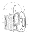
FIGURE 4 shows an example boroscope inspection device used to inspect theFigure 2 blade. -
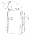
FIGURE 5 shows another view of theFigure 4 boroscope inspection device. -
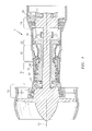
FIGURE 6 shows a close-up view of a probe of theFigure 4 boroscope inspection device. -
FIGURE 7 shows a section view at line 7-7 inFigure 6 . - Referring to
Figure 1 , an example turbomachine, such as agas turbine engine 10, is circumferentially disposed about anaxis 12. Thegas turbine engine 10 includes afan 14, a lowpressure compressor section 16, a highpressure compressor section 18, acombustion section 20, a highpressure turbine section 22, and a lowpressure turbine section 24. Other example turbomachines may include more or fewer sections. - During operation, air is compressed in the low
pressure compressor section 16 and the highpressure compressor section 18. The compressed air is then mixed with fuel and burned in thecombustion section 20. The products of combustion are expanded across the highpressure turbine section 22 and the lowpressure turbine section 24. - The high
pressure compressor section 18 includes arotor 32. The lowpressure compressor section 16 includes arotor 33. Therotors axis 12. The example rotors 32 and 33 include alternating rows of rotating airfoils orrotating blades 34 and static airfoils orstatic blades 36. Thestatic blades 36 may also be referred to as static vanes. - The high
pressure turbine section 22 includes arotor 26. The lowpressure turbine section 24 includes arotor 27. Therotors axis 12 in response to expansion to drive the highpressure compressor section 18 and the lowpressure compressor section 16. The example rotors 26 and 27 include rotating arrays ofblades 28, for example. - The example turbomachine described in this disclosure is not limited to the two spool gas turbine architecture described, however, and may be used in other architectures, such as the single spool axial design, a three spool axial design, and still other architectures. That is, there are various types of gas turbine engines, and other turbomachines, that can benefit from the examples disclosed herein.
- Referring to
Figures 2-3 , anexample blade 50 from theFigure 1 turbomachine extends axially from a base 52 to atip 54. Theblade 50 includes aradially extending airfoil 56. - In this example, the
blade 50 is one of the rotating blades from therotor 32. In other examples, theblade 50 is a stationary blade, or a blade from the one of theturbine sections - The
example blade 50 has been used within theengine 10 and is being refurbished for the purpose of reinstallation into theengine 10. Example refurbishing processes may include acid stripping blades, reapplying coatings to blades, adding new tips to blades, adding additional material to worn areas of blades.. - The
example blade 50 establishes a plurality ofinternal passages 58. In this example,apertures 60 established in the base 52 represent the starting point forinternal passages 58, and cooling holes 62 represent the termination point. During operation, a cooling airflow moves from anair supply 61 into theinternal passages 58 through theapertures 60. The cooling airflow exits theinternal passages 58 through the cooling holes 62. - The cooling airflow moving through the
internal passages 58 of theblade 50 cools theblade 50. Also, air exiting theinternal passages 58 through the cooling holes 62 may cool theblade 50 by film cooling, for example. Theinternal passages 58 are a type of fluid communication paths. - Only a few
internal passages 58 and cooling holes 62 are shown in this example. A person having skill in this art and the benefit of this disclosure would understand that many moreinternal passages 58 and cooling holes 62 may be established within theblade 50 depending on specific design requirements. Further, although the exampleinternal passages 58 are relatively linear, other examples may include serpentine passages, or passages that follow other paths. - Referring now to
Figures 4 and5 with continuing reference toFigures 2 and3 , an exampleboroscope inspection device 66 is used to inspect theinternal passages 58 of theblade 50. Theinspection device 66 may revealinternal passages 58 that are blocked, for example. Such blockages prevent a cooling airflow from moving through some portions of theblade 50, which can undesirably result in thermal energy concentrations within theblade 50. Theinspection device 66 may be used to inspect a blade that is being refurbished or to inspect a newly manufactured blade. - The
example inspection device 66 includes aprobe 68 having aprobe tip 70. Avideo camera 72 is removably attachable to theprobe 68. In some examples, an adapter may be required to attach thevideo camera 72 and theprobe 68. - The
example video camera 72 is operatively linked to adisplay 74 and abattery 76. Thedisplay 74 includes adisplay screen 78 that shows images inspected by theprobe 68. A person having skill in this art and the benefit of this disclosure would understand how to display the images of the inspected areas on thedisplay screen 78. The display screen is a 7 inch (17.78 centimeter) display screen in this example. The images show a blockage within theinternal passages 58. - In this example, the
display 74 and thevideo camera 72 are both powered exclusively by thebattery 76. Theexample battery 76 is a 12 volt, 5.2 amp rechargeable battery. The life of theexample battery 76 is about 3.0 hours. A recharging station may be used to recharge thebattery 76 when theinspection device 66 is not in use. - The
example inspection device 66 also includes a light 80 that is removably attachable to theprobe 68. The light 80 is used to illuminate areas inspected by theprobe 68, such as theinternal passages 58. - A
wriststrap 81 is attached to the light 80 to help an inspector secure theprobe 68 and the light 80 during an inspection procedure. - The
example inspection device 66 includes aprotective case 82 that holds thebattery 76, thedisplay 74, and thevideo camera 72. During an inspection procedure, thevideo camera 72 may be removed from theprotective case 82 or may stay within theprotective case 82. Theprobe 68 typically remains outside theprotective case 82, along with the light 80, regardless the location of thevideo camera 72. - The example protective case includes a
lid 84 that establishes anaperture 86. Theaperture 86 allows a user, such as the inspector, to view at least a portion of thedisplay screen 78 when thelid 84 is closed. A clearprotective cover 87 is used in this example to protect against damage to thescreen 78 through theaperture 86, which is about 1.5 inches (3.81 cm) in this example. The exampleprotective case 82 is 14 inches (45.56 cm) long, 10 inches (25.4 cm) wide, and 3.5 inches (8.89 cm) tall. - In this example, the
lid 84 of theprotective case 82 is closed when thelid 84 is placed over abase 88 of theprotective case 82. Thelid 84 is hinged to the base 88 in this example.Figure 4 shows theprotective case 82 in an open position, andFigure 5 shows theprotective case 82 in a closed position. Notably, an inspection may be carried out with theprotective case 82 in a closed position. - An on/off
switch 90 is secured within thelid 84 of the exampleprotective case 82. An inspector actuates the on/offswitch 90 to selectively supply power to thevideo camera 72 and thedisplay 74 from thebattery 76. Theprotective case 82 also includes a charging location (not shown) for thebattery 76 so that thebattery 76 may be recharged at the 110V recharging station without requiring the operator to open theprotective case 82. Wiring connects the various components of theinspection device 66 where needed. - During an inspection procedure utilizing the
inspection device 66, the inspector may transport theinspection device 66 to theblade 50 using a carryinghandle 83 established within theprotective case 82. Theprobe tip 70 is then inserted through theaperture 60 established within thebase 52 of theblade 50. The inspector may be required to attach theprobe 68 and light 80 to thevideo camera 72 prior to insertion of theprobe tip 70. Notably, the shape of theprobe tip 70 allows the inspector to inspect the full radial length of theinternal passages 58 by continuing to insert theprobe tip 70 into theaperture 60. Theprobe tip 70 is flexible, which also facilitates inspection. - The inspection may reveal, for example, foreign material, corrosion, and damage within the
internal passages 58. Theprobe tip 70 may be used to inspect internal trip strips in some examples. In some examples, the inspection utilizing theinspection device 66 is coupled with inspections utilizing a magnitoscope, which may improve detection of corrosion. - Typical blades inspected by the
inspection device 66 are between 3 inches (76.2 mm) and 10 inches (254 mm) long. Theexample probe tip 70 is longer than the typical blades to provide the operator with adequate length to manipulate the position of theprobe tip 70. Although described as ainspection device 66 used to inspect theinternal passages 58 of ablade 50, theinspection device 66 may be used to inspect other areas of theengine 10 requiring a relatively slender probe tip. - Referring now to
Figures 6 and 7 with continued reference toFigure 3 , anexample probe tip 70 has a length 1 that is between 17-3/8 inches (44.1325 cm) and 29-3/8 inches (74.6125 cm). In one specific example, theprobe tip 70 is 25 inches (63.5 cm) with a tolerance of +/- 1/8 inch (3.175 cm). The diameter d of theexample probe tip 70 is about 0.03 inches (0.762 mm). Other examples may include probe tips having diameters that are between 0.02 inches (0.508 mm) and 0.04 inches (1.016 mm). The relatively slender nature and flexibility of theexample probe tip 70 facilitates insertion of theprobe tip 70 into the internal passages of theblade 50. Typically, a ratio of the length 1 of theprobe tip 70 to the diameter d of theprobe tip 70 is between 434 and 1,469. - Features of the disclosed examples include an inspection device that may be transported to the location of a blade requiring inspection, rather than requiring transport of the blade to the inspection device. Another feature of the example inspection device is a probe tip suitable for inspection fluid communication paths within turbomachine blades. The inspection device displays images from a display screen within a protective case that also houses the battery.
- The preceding description is exemplary rather than limiting in nature. Variations and modifications to the disclosed examples may become apparent to those skilled in the art that do not necessarily depart from the essence of this disclosure. Thus, the scope of legal protection given to this disclosure can only be determined by studying the following claims.
Claims (15)
- A portable boroscope assembly (66) for inspecting passages (58) within a turbomachine blade (50), comprising:a boroscope probe (68);a display screen (78) configured to show images of areas inspected by the boroscope probe (68);a battery (76) that powers the display screen (78); anda protective case (82) configured to hold at least the display (78) and the battery (76), the protective case (82) defining an aperture (86), wherein at least portion of the display screen (78) is viewable through the aperture (86).
- The portable boroscope assembly of claim 1, including a light (80) positioned outside the protective case (82), the light configured to be powered by the battery (76).
- The portable boroscope assembly of claim 1 or 2, including a video camera (72) that is powered by the battery (76), the protective case (82) further configured to hold the video camera (72).
- The portable boroscope assembly of claim 1, 2 or 3, wherein the probe (68) comprises a probe tip (70) configured to be inserted into an internal passage (58) of a turbine blade (50).
- A portable boroscope assembly (66) for inspecting passages (58) within a turbomachine blade (50), comprising:a video camera (72);a probe tip (71) operatively coupled with the camera (72);a display (74);a light (80) operatively coupled to the probe tip (71);a battery (76) that powers the video camera (72), the display (74), and the light (80) ; anda protective case (82) configured to hold the at least the display (74) and the battery (76).
- The portable boroscope assembly of claim 4 or 5, wherein the probe tip (71) has a length that is between 17.375 and 29.375 inches (44.1325 cm and 74.6125 mm).
- The portable boroscope assembly of claim 4, 5 or 6, wherein the probe tip (71) has a diameter that is between 0.02 and 0.04 inches (0.508 mm and 1.016 mm).
- The portable boroscope assembly of any of claims 4 to 7, wherein a ratio of a length of the probe tip (71) to a diameter of the probe tip (71) is between 434 and 1469.
- The portable boroscope assembly of any of claims 5 to 8, wherein the probe tip (71) is configured to be inserted into an internal passage (58) established within a blade (50).
- The portable boroscope assembly of any preceding claim, wherein the protective case (86) is configured to hold at least a portion of the probe (68).
- The portable boroscope assembly of any preceding claim, wherein the battery (76) is a rechargeable battery.
- A turbomachine blade boroscope inspection method, comprising:powering a boroscope inspection device (66) using a battery (76); andinspecting a fluid passage (58) established within a turbomachine blade (50) using the boroscope inspection device (66).
- The turbomachine blade boroscope inspection method of claim 12, further including holding the battery (76) and a display screen (78) of the boroscope inspection device within a protective case (82).
- The turbomachine blade boroscope inspection method of claim 13, including displaying an image of the turbomachine through an aperture (86) established in the case (82).
- The turbomachine blade boroscope inspection method of claim 12, 13 or 14, including recharging the battery (76).
Applications Claiming Priority (1)
| Application Number | Priority Date | Filing Date | Title |
|---|---|---|---|
| US13/039,596 US20120224048A1 (en) | 2011-03-03 | 2011-03-03 | Portable boroscope for inspecting turbomachine blades |
Publications (2)
| Publication Number | Publication Date |
|---|---|
| EP2495553A2 true EP2495553A2 (en) | 2012-09-05 |
| EP2495553A3 EP2495553A3 (en) | 2012-12-19 |
Family
ID=45977142
Family Applications (1)
| Application Number | Title | Priority Date | Filing Date |
|---|---|---|---|
| EP12157774A Ceased EP2495553A3 (en) | 2011-03-03 | 2012-03-01 | Portable boroscope for inspecting turbomachine blades |
Country Status (2)
| Country | Link |
|---|---|
| US (1) | US20120224048A1 (en) |
| EP (1) | EP2495553A3 (en) |
Cited By (3)
| Publication number | Priority date | Publication date | Assignee | Title |
|---|---|---|---|---|
| EP2789809A1 (en) | 2013-04-12 | 2014-10-15 | Alstom Technology Ltd | Method for automatic positioning of a gas turbine rotor |
| EP2796670A1 (en) | 2013-04-23 | 2014-10-29 | Alstom Technology Ltd | Gas turbine rotor positioning device |
| EP2835497A3 (en) * | 2013-08-07 | 2015-04-15 | General Electric Company | Remote turbine component replacement apparatus and method of remotely replacing a turbine component |
Families Citing this family (6)
| Publication number | Priority date | Publication date | Assignee | Title |
|---|---|---|---|---|
| EP2594738A1 (en) * | 2011-11-18 | 2013-05-22 | MTU Aero Engines GmbH | Processing device and method for operating a seal element inside a housing of a gas turbine |
| DE102011122549A1 (en) * | 2011-12-28 | 2013-07-04 | Rolls-Royce Deutschland Ltd & Co Kg | Method for repairing an inlet layer of a compressor of a gas turbine |
| US20140267677A1 (en) * | 2013-03-14 | 2014-09-18 | General Electric Company | Turbomachine component monitoring system and method |
| US10295475B2 (en) | 2014-09-05 | 2019-05-21 | Rolls-Royce Corporation | Inspection of machined holes |
| US10228669B2 (en) | 2015-05-27 | 2019-03-12 | Rolls-Royce Corporation | Machine tool monitoring |
| DE102016216895B4 (en) * | 2016-09-06 | 2019-02-28 | Lufthansa Technik Ag | Method for unique position assignment and identification of a turbine blade |
Citations (3)
| Publication number | Priority date | Publication date | Assignee | Title |
|---|---|---|---|---|
| US6068119A (en) * | 1996-07-18 | 2000-05-30 | Testo Gmbh & Co. | Watertight protective device for holding a measuring or display device |
| US6554765B1 (en) * | 1996-07-15 | 2003-04-29 | East Giant Limited | Hand held, portable camera with adaptable lens system |
| US20050030707A1 (en) * | 2001-11-19 | 2005-02-10 | Richardson Curtis R. | Protective enclosure for an interactive flat-panel controlled device |
Family Cites Families (12)
| Publication number | Priority date | Publication date | Assignee | Title |
|---|---|---|---|---|
| GB9805861D0 (en) * | 1998-03-20 | 1998-05-13 | Rolls Royce Plc | A method and an apparatus for inspecting articles |
| US6953432B2 (en) * | 2003-05-20 | 2005-10-11 | Everest Vit, Inc. | Imager cover-glass mounting |
| US20050050707A1 (en) * | 2003-09-05 | 2005-03-10 | Scott Joshua Lynn | Tip tool |
| US7758495B2 (en) * | 2005-01-10 | 2010-07-20 | Perceptron, Inc. | Remote inspection device |
| US7956888B2 (en) * | 2005-06-22 | 2011-06-07 | Ge Inspection Technologies, Lp | Remote video inspection system integrating audio communication functionality |
| US7458768B2 (en) * | 2005-06-28 | 2008-12-02 | United Technologies Corporation | Borescope inspection port device for gas turbine engine and gas turbine engine using same |
| US8523764B2 (en) * | 2005-12-07 | 2013-09-03 | Siemens Energy, Inc. | Remote viewing apparatus |
| US7679041B2 (en) * | 2006-02-13 | 2010-03-16 | Ge Inspection Technologies, Lp | Electronic imaging device with photosensor arrays |
| US7902990B2 (en) * | 2007-10-26 | 2011-03-08 | Ge Inspection Technologies, Lp | Battery and power management for industrial inspection handset |
| GB2493606B (en) * | 2008-03-07 | 2013-03-27 | Milwaukee Electric Tool Corp | Visual inspection device |
| US20100033986A1 (en) * | 2008-08-05 | 2010-02-11 | Perceptron Inc. | Light Pipe For Imaging Head of Video Inspection Device |
| US8532956B2 (en) * | 2008-10-27 | 2013-09-10 | General Electric Company | Method and system for rotation tracking of a turbomachine component |
-
2011
- 2011-03-03 US US13/039,596 patent/US20120224048A1/en not_active Abandoned
-
2012
- 2012-03-01 EP EP12157774A patent/EP2495553A3/en not_active Ceased
Patent Citations (3)
| Publication number | Priority date | Publication date | Assignee | Title |
|---|---|---|---|---|
| US6554765B1 (en) * | 1996-07-15 | 2003-04-29 | East Giant Limited | Hand held, portable camera with adaptable lens system |
| US6068119A (en) * | 1996-07-18 | 2000-05-30 | Testo Gmbh & Co. | Watertight protective device for holding a measuring or display device |
| US20050030707A1 (en) * | 2001-11-19 | 2005-02-10 | Richardson Curtis R. | Protective enclosure for an interactive flat-panel controlled device |
Cited By (6)
| Publication number | Priority date | Publication date | Assignee | Title |
|---|---|---|---|---|
| EP2789809A1 (en) | 2013-04-12 | 2014-10-15 | Alstom Technology Ltd | Method for automatic positioning of a gas turbine rotor |
| EP2789810A1 (en) | 2013-04-12 | 2014-10-15 | Alstom Technology Ltd | Method for automatic positioning of a gasturbine rotor |
| US9671792B2 (en) | 2013-04-12 | 2017-06-06 | Ansaldo Energia Ip Uk Limited | Method for automatic positioning of a gas turbine rotor |
| EP2796670A1 (en) | 2013-04-23 | 2014-10-29 | Alstom Technology Ltd | Gas turbine rotor positioning device |
| US9683461B2 (en) | 2013-04-23 | 2017-06-20 | Ansaldo Energia Switzerland AG | Gas turbine rotor positioning device |
| EP2835497A3 (en) * | 2013-08-07 | 2015-04-15 | General Electric Company | Remote turbine component replacement apparatus and method of remotely replacing a turbine component |
Also Published As
| Publication number | Publication date |
|---|---|
| EP2495553A3 (en) | 2012-12-19 |
| US20120224048A1 (en) | 2012-09-06 |
Similar Documents
| Publication | Publication Date | Title |
|---|---|---|
| EP2495553A2 (en) | Portable boroscope for inspecting turbomachine blades | |
| US11739695B2 (en) | Gas turbine engine maintenance tool | |
| US11111813B2 (en) | Gas turbine engine maintenance method | |
| US10217208B2 (en) | Apparatus and a method of inspecting a turbomachine | |
| JP5681520B2 (en) | Stator vane inspection system and method | |
| EP3399160A1 (en) | Method of inspecting a gas turbine engine | |
| US11225869B2 (en) | In situ gas turbine prevention of crack growth progression | |
| EP3561495A1 (en) | Inspection and maintenance apparatus | |
| CN102687058A (en) | Inspection device and method for positioning an inspection device | |
| EP3647534A1 (en) | Turbine component performance inspection sleeve and method of inspecting engine component | |
| EP3203019B1 (en) | Method of joining material to a surface area of a component of a gas turbine engine | |
| EP3808944A1 (en) | Maintenance system with tubular assembly for servicing a turbomachine | |
| US20070128385A1 (en) | Methods and systems for turbine rotor balancing | |
| SG10202100891RA (en) | Engine inspection and maintenance tool | |
| EP3203018B1 (en) | Method of remotely stopping a crack in a component of a gas turbine engine | |
| US11053859B2 (en) | Gas turbine engine having a metallic test sample and a method of determining the service life of a gas turbine engine component using a metallic test sample | |
| EP3705690A1 (en) | Cover secured by captive fastener | |
| CA2957264A1 (en) | In situ gas turbine prevention of crack growth progression |
Legal Events
| Date | Code | Title | Description |
|---|---|---|---|
| PUAI | Public reference made under article 153(3) epc to a published international application that has entered the european phase |
Free format text: ORIGINAL CODE: 0009012 |
|
| AK | Designated contracting states |
Kind code of ref document: A2 Designated state(s): AL AT BE BG CH CY CZ DE DK EE ES FI FR GB GR HR HU IE IS IT LI LT LU LV MC MK MT NL NO PL PT RO RS SE SI SK SM TR |
|
| AX | Request for extension of the european patent |
Extension state: BA ME |
|
| PUAL | Search report despatched |
Free format text: ORIGINAL CODE: 0009013 |
|
| AK | Designated contracting states |
Kind code of ref document: A3 Designated state(s): AL AT BE BG CH CY CZ DE DK EE ES FI FR GB GR HR HU IE IS IT LI LT LU LV MC MK MT NL NO PL PT RO RS SE SI SK SM TR |
|
| AX | Request for extension of the european patent |
Extension state: BA ME |
|
| RIC1 | Information provided on ipc code assigned before grant |
Ipc: F01D 21/00 20060101ALI20121115BHEP Ipc: F01D 5/00 20060101ALI20121115BHEP Ipc: G01N 21/954 20060101AFI20121115BHEP Ipc: G02B 23/24 20060101ALI20121115BHEP |
|
| 17P | Request for examination filed |
Effective date: 20130618 |
|
| RBV | Designated contracting states (corrected) |
Designated state(s): AL AT BE BG CH CY CZ DE DK EE ES FI FR GB GR HR HU IE IS IT LI LT LU LV MC MK MT NL NO PL PT RO RS SE SI SK SM TR |
|
| RAP1 | Party data changed (applicant data changed or rights of an application transferred) |
Owner name: UNITED TECHNOLOGIES CORPORATION |
|
| STAA | Information on the status of an ep patent application or granted ep patent |
Free format text: STATUS: EXAMINATION IS IN PROGRESS |
|
| 17Q | First examination report despatched |
Effective date: 20161201 |
|
| STAA | Information on the status of an ep patent application or granted ep patent |
Free format text: STATUS: THE APPLICATION HAS BEEN REFUSED |
|
| 18R | Application refused |
Effective date: 20181029 |