EP2495518A2 - Fluidised bed drier system - Google Patents
Fluidised bed drier system Download PDFInfo
- Publication number
- EP2495518A2 EP2495518A2 EP12152063A EP12152063A EP2495518A2 EP 2495518 A2 EP2495518 A2 EP 2495518A2 EP 12152063 A EP12152063 A EP 12152063A EP 12152063 A EP12152063 A EP 12152063A EP 2495518 A2 EP2495518 A2 EP 2495518A2
- Authority
- EP
- European Patent Office
- Prior art keywords
- fluidized
- coal
- bed dryer
- dryer arrangement
- fluidized bed
- Prior art date
- Legal status (The legal status is an assumption and is not a legal conclusion. Google has not performed a legal analysis and makes no representation as to the accuracy of the status listed.)
- Withdrawn
Links
- 238000010438 heat treatment Methods 0.000 claims abstract description 38
- 239000012530 fluid Substances 0.000 claims abstract description 22
- 238000000034 method Methods 0.000 claims abstract description 7
- 239000003245 coal Substances 0.000 claims description 44
- 238000002156 mixing Methods 0.000 claims description 13
- 238000001035 drying Methods 0.000 claims description 10
- 239000002245 particle Substances 0.000 claims description 5
- 230000015572 biosynthetic process Effects 0.000 description 8
- 238000005243 fluidization Methods 0.000 description 6
- 239000003077 lignite Substances 0.000 description 5
- 238000009833 condensation Methods 0.000 description 4
- 230000005494 condensation Effects 0.000 description 4
- XLYOFNOQVPJJNP-UHFFFAOYSA-N water Substances O XLYOFNOQVPJJNP-UHFFFAOYSA-N 0.000 description 4
- OKTJSMMVPCPJKN-UHFFFAOYSA-N Carbon Chemical compound [C] OKTJSMMVPCPJKN-UHFFFAOYSA-N 0.000 description 3
- 229910052799 carbon Inorganic materials 0.000 description 3
- 238000004140 cleaning Methods 0.000 description 2
- 239000002817 coal dust Substances 0.000 description 2
- 238000009826 distribution Methods 0.000 description 2
- 238000012544 monitoring process Methods 0.000 description 2
- 230000003068 static effect Effects 0.000 description 2
- 230000006978 adaptation Effects 0.000 description 1
- 239000003795 chemical substances by application Substances 0.000 description 1
- 238000005520 cutting process Methods 0.000 description 1
- 230000006378 damage Effects 0.000 description 1
- 230000001419 dependent effect Effects 0.000 description 1
- 230000000694 effects Effects 0.000 description 1
- 238000011010 flushing procedure Methods 0.000 description 1
- 239000011521 glass Substances 0.000 description 1
- 238000012423 maintenance Methods 0.000 description 1
- 239000000203 mixture Substances 0.000 description 1
- 238000005192 partition Methods 0.000 description 1
- 230000000007 visual effect Effects 0.000 description 1
Images


Classifications
-
- F—MECHANICAL ENGINEERING; LIGHTING; HEATING; WEAPONS; BLASTING
- F23—COMBUSTION APPARATUS; COMBUSTION PROCESSES
- F23K—FEEDING FUEL TO COMBUSTION APPARATUS
- F23K1/00—Preparation of lump or pulverulent fuel in readiness for delivery to combustion apparatus
- F23K1/04—Heating fuel prior to delivery to combustion apparatus
-
- F—MECHANICAL ENGINEERING; LIGHTING; HEATING; WEAPONS; BLASTING
- F26—DRYING
- F26B—DRYING SOLID MATERIALS OR OBJECTS BY REMOVING LIQUID THEREFROM
- F26B3/00—Drying solid materials or objects by processes involving the application of heat
- F26B3/02—Drying solid materials or objects by processes involving the application of heat by convection, i.e. heat being conveyed from a heat source to the materials or objects to be dried by a gas or vapour, e.g. air
- F26B3/06—Drying solid materials or objects by processes involving the application of heat by convection, i.e. heat being conveyed from a heat source to the materials or objects to be dried by a gas or vapour, e.g. air the gas or vapour flowing through the materials or objects to be dried
- F26B3/08—Drying solid materials or objects by processes involving the application of heat by convection, i.e. heat being conveyed from a heat source to the materials or objects to be dried by a gas or vapour, e.g. air the gas or vapour flowing through the materials or objects to be dried so as to loosen them, e.g. to form a fluidised bed
- F26B3/084—Drying solid materials or objects by processes involving the application of heat by convection, i.e. heat being conveyed from a heat source to the materials or objects to be dried by a gas or vapour, e.g. air the gas or vapour flowing through the materials or objects to be dried so as to loosen them, e.g. to form a fluidised bed with heat exchange taking place in the fluidised bed, e.g. combined direct and indirect heat exchange
-
- F—MECHANICAL ENGINEERING; LIGHTING; HEATING; WEAPONS; BLASTING
- F23—COMBUSTION APPARATUS; COMBUSTION PROCESSES
- F23K—FEEDING FUEL TO COMBUSTION APPARATUS
- F23K2201/00—Pretreatment of solid fuel
- F23K2201/20—Drying
Definitions
- Coal in particular raw lignite, contains a high proportion of water.
- a fluidized bed dryer can be used.
- a fluidized bed dryer comprises a container into which the raw coal is introduced via a coal manhole in the upper area.
- a nozzle bottom is arranged in the lower part of the container.
- the nozzle bottom has a plurality of upwardly directed nozzles. From the nozzles, a fluid, such as vapor (vapors) exits with pressure.
- the coal is blown up and forms a fluidized bed with quasi-fluid properties.
- a heating arrangement is provided with a plurality of parallel heating tubes. The heating pipes are traversed by heating steam and transfer heat to the fluidized bed.
- a fluidized-bed dryer arrangement is disclosed, for example, on the Internet at www.kohletrocknung.de.
- the fluidized-bed dryer has an elongate, substantially cylindrical container with a nozzle bottom and a heating arrangement.
- the longitudinal axis of the container is vertical.
- the heating arrangement consists of a plurality of parallel heating pipes or heating plates.
- the heating pipes or plates extend in the horizontal direction.
- the longitudinal axis of the container is perpendicular to it in a vertical direction.
- the heating pipes are held in vertical holders in the form of a steam distributor or condensate collector.
- the heating pipes extend over the entire circular cross-section of the container. In the middle area, the heating pipes are correspondingly longer than in the edge area.
- the object is achieved in that the emerging from different nozzles of the nozzle bottom fluid flow is different.
- a higher fluid flow can be used.
- the incoming raw coal is mixed very well.
- a stable and homogeneous fluidized bed can be operated with high heat transfer rates.
- a higher fluidization means that the loosening point of the fluidized bed is significantly exceeded according to the particle size.
- the fluidized bed is influenced accordingly so that the clods do not even form. A separate distribution device is no longer required.
- the individual zones in the fluidized bed can be fluidized differently.
- the different amounts of fluidization are adjusted via valves in the supply lines.
- the fluid flow of several nozzles of the nozzle plate may be the same zone-wise and different in different zones.
- the zones comprise at least one mixing zone in the edge region of the dryer arrangement and a drying zone in the central region of the dryer arrangement.
- a mixing zone is provided under each coal manhole.
- the fluid flow exiting from different nozzles of the nozzle base has a different fluid velocity.
- separating plates are arranged between the zones. Then the zones are physically separated. The coal can only enter the dryer zone if it is already pre-dried. In this way, floe formation is avoided even in the dryer zone.
- the dividing plates can also be used to mechanically hold heating pipes.
- the arrangement is particularly suitable when the heating tubes are elongated and form a Schundbeckp which is substantially wider than at least in one direction.
- a fluid for producing a fluidized bed emerges from the nozzles of a nozzle base, wherein the fluid emerges in a mixing zone at a higher speed than in a dryer zone.
- the velocity of the fluid flow in the mixing zone is preferably adjustable and is between 0.05 and 0.2 m / s, preferably 0.09 to 0.11 m / s higher than in the dryer zone.
- the drying zone is centrally located in the dryer and is fluidized near the loosening point. This is a safe overrun of Losening point sought to avoid the collapse of the fluidized bed or parts thereof.
- the figures show a fluidized bed dryer arrangement.
- the arrangement is used to dry raw lignite.
- the fluidized bed dryer assembly comprises a container with a container shell 1 in a saddle bearing 18.
- the container is formed substantially cylindrical. At the end faces of the container is curved outward.
- the container is heated with a container heater 16, which has a condensate collector 17.
- the container is under a pressure of 4 bar.
- the container heater 16 is fed from a distributor 15 with heating steam.
- coal manholes 2 are provided in the upper part of the container.
- suitable locks such as a rotary valve, are provided which allow the introduction of coal in the standing under a pressure of 4 bar container.
- two vapor withdrawals 3 are arranged with a static separator 31. About the vapor exhausts 3 loaded with coal dust steam is discharged from the container interior.
- dry lignite is fed via the feed 4 into the dryer. Dry lignite, which has been filtered from the vapors by means of a vapor filter, is returned via a return 5 in the container interior.
- part of the pulverized coal is separated by a static separator 31, which then remains in the fluidized-bed dryer.
- a static separator 31 which then remains in the fluidized-bed dryer.
- a boarding door 6 is provided in the central region of the container shell. Laterally next to the access door 6, a sootblower 7 is provided for Schutulatgraphy during the Abfahrvones and the destruction of coal floes.
- the sootblower is a cleaning device which, during draining of the dryer, i. during the shutdown prevents dry carbon deposits on the Schundrohren.
- the sootblower 7 is operated with steam as a cleaning medium. At the same time, floe formation (coal lumps) occurring during operation due to targeted steam pulses can be destroyed on the fluidized bed surface.
- the rinsing device 30 is a rinsing nozzle, with which carbon deposits are eliminated on the dryer floor during emptying of the dryer.
- a nozzle bottom 28 is arranged. From the nozzles of the nozzle plate 28 exits pressurized steam. With this steam, a fluidized bed of coal is produced. Part of the fluidization steam can be introduced via side nozzles 32 in the upper region of the fluidized bed in order to support the turbulence and thus the interference of the moist raw carbon.
- the nozzles of the nozzle bottom are charged with different amounts of steam.
- a larger amount of steam exits the nozzles than in the middle region.
- too high steam quantities are uneconomical. It is therefore desirable to produce the fluidized bed with as little steam as possible.
- the raw coal has a high water content in the range of, for example, 50-60%. The surface moisture therefore leads to bonding. If the raw coal from the coal manholes 2 comes down, there is a risk of floe formation. A higher amount of steam from the nozzles of the nozzle bottom 28 below the coal manholes 2 increases the particle velocity and avoids the risk of floe formation. In the dryer zone in the middle area of the nozzle bottom, this high amount of steam is not required. There you can work with usual amounts of steam. In this way, it continues to work with a minimum of steam.
- a condensation heating surface 22 is arranged in the lower, central region of the container above the nozzle bottom.
- the Kondensationsterrorism composition 22 consists of a plurality of parallel heating tubes of equal length. It extends over the entire length of the substantially cylindrical part of the container.
- the heating pipes are held by a support 26.
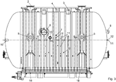
- the longitudinal axis of the heating pipes runs from right to left in FIG. 4 parallel to the longitudinal axis of the container.
- cross section in FIG. 6 It can be seen that the heating pipes almost extend to the container wall zoom. As a result, the dead volume is kept low.
- the heating tubes of the condensation heating surface 22 are welded to a perforated plate 27.
- the perforated plate 27 is part of a partition wall between the fluidized bed and a laterally arranged antechamber. Together with the perforated plate 27 forms a hemispherical shell an inlet chamber 21. On the output side, the corresponding perforated plate with a hemispherical shell forms an outlet chamber 23.
- the inlet chamber 21 is connected via connecting tubes 20 with a heating steam inlet 9.
- the inlet chamber 21 has a condensate drain 25.
- the outlet chamber 23 has a condensate drain 24. Heating steam enters via the Schudampfeinberg 9 and the connecting pipes 20 in the inlet chamber 21 a. This forms a distributor.
- the heating steam passes through the holes in the perforated plate 27 in the welded thereto heating tubes the Kondensations2020 Structure 22.
- the Wiendampfkondensat passes through the holes of the perforated plate 27 in the outlet chamber 23. This forms a collector. Due to the condensate drain 24 occurs water, which is condensed in the fluidized bed in the heating tubes, again from.
- the coal entering through the coal manhole 2 enters the fluidized bed.
- the fluidized bed is heated and dried.
- the dry lignite is transported via a connection shaft 29 in the bottom of the container to a screw conveyor. There it is available for further use.
- the inlet and outlet chambers 21 and 23 can be hemispherical in shape.
- the monitoring of the arrangement is done with measuring instruments. These include thermocouples, which are arranged at temperature measuring points 11 and pressure gauge for measuring the pressure at pressure measuring points 12. A visual monitoring of the drying process via a sight glass 13 with flushing.
- the condensation heating surface 22 has a continuous, vertical lane 14 in the longitudinal direction of the container 1. There are no heating pipes in it.
- the vertical lane is directly below the coal manholes 2 in the center of the vessel. With the lane 14 improved mixing of the raw coal is achieved in the dry coal. The raw coal is better distributed and can not remain above the coal bed of the fluidized bed. The coal top edge is not too close above the condensation heating surface to avoid floe formation. A gap in the dry area leads to a good introduction of the raw coal.
Landscapes
- Engineering & Computer Science (AREA)
- Mechanical Engineering (AREA)
- General Engineering & Computer Science (AREA)
- Life Sciences & Earth Sciences (AREA)
- Microbiology (AREA)
- Chemical & Material Sciences (AREA)
- Combustion & Propulsion (AREA)
- Drying Of Solid Materials (AREA)
- Solid Fuels And Fuel-Associated Substances (AREA)
Abstract
Description
Die Erfindung betrifft eine Wirbelschicht-Trockneranordnung zur Trocknung von Kohle, enthaltend
- (a) einen Behälter;
- (b) eine Heizungsanordnung mit einer Vielzahl von parallelen Heizrohren oder - platten; und
- (c) einen Düsenboden mit einer Vielzahl von Düsen zur Erzeugung einer Wirbelschicht.
- (a) a container;
- (b) a heater assembly having a plurality of parallel heating tubes or plates; and
- (C) a nozzle plate having a plurality of nozzles for generating a fluidized bed.
Kohle, insbesondere Roh-Braunkohle enthält einen hohen Wasseranteil. Vor der Verbrennung in einem Kraftwerksprozess wird die Kohle gemahlen und getrocknet. Für die Trocknung kann ein Wirbelschicht-Trockner eingesetzt werden. Ein Wirbelschicht-Trockner umfasst einen Behälter, in welchen die Rohkohle über einen Kohleeinfallschacht im oberen Bereich eingebracht wird. Im unteren Bereich des Behälters ist ein Düsenboden angeordnet. Der Düsenboden weist eine Vielzahl von nach oben gerichteten Düsen auf. Aus den Düsen tritt ein Fluid, z.B. Dampf (Brüden) mit Druck aus. Die Kohle wird so nach oben geblasen und bildet eine Wirbelschicht mit quasi fluiden Eigenschaften. In der Wirbelschicht ist eine Heizungsanordnung mit einer Vielzahl von parallelen Heizrohren vorgesehen. Die Heizrohre sind von Heizdampf durchflossen und übertragen Wärme auf die Wirbelschicht.Coal, in particular raw lignite, contains a high proportion of water. Before burning in a power plant process, the coal is ground and dried. For drying, a fluidized bed dryer can be used. A fluidized bed dryer comprises a container into which the raw coal is introduced via a coal manhole in the upper area. In the lower part of the container, a nozzle bottom is arranged. The nozzle bottom has a plurality of upwardly directed nozzles. From the nozzles, a fluid, such as vapor (vapors) exits with pressure. The coal is blown up and forms a fluidized bed with quasi-fluid properties. In the fluidized bed a heating arrangement is provided with a plurality of parallel heating tubes. The heating pipes are traversed by heating steam and transfer heat to the fluidized bed.
Eine Wirbelschicht-Trockneranordnung ist beispielsweise im Internet, unter www.kohletrocknung.de offenbart.A fluidized-bed dryer arrangement is disclosed, for example, on the Internet at www.kohletrocknung.de.
Bei bekannten Anordnungen besteht die Gefahr der Schollenbildung. Dieser Effekt tritt auf, wenn sehr feuchte Kohle, beispielsweise Rohkohle mit 50-60% Wassergehalt aus dem Kohleeinfallschacht verklebt und als Klumpen auf die Oberfläche der Wirbelschicht gelangt. Die feuchte Kohle hat eine hohe Oberflächenfeuchte. Die Kohleklumpen, die sich dabei bilden, setzen sich auf den oberen Heizrohren fest und bilden "Schollen". Diese sind ungünstig für die Wirbelschicht.In known arrangements, there is a risk of floe formation. This effect occurs when very wet coal, for example, raw coal with 50-60% water content glued from the coal manhole and gets as a lump on the surface of the fluidized bed. The wet coal has a high surface moisture. The lumps of coal that form, settle on the upper heating pipes and form "floes". These are unfavorable for the fluidized bed.
Es ist Aufgabe der Erfindung, einen Wirbelschicht-Trockner der eingangs genannten Art ohne zusätzliche Verteileinrichtung zu schaffen, bei welchem die Wirbelschicht auf einfache Weise vor Schollenbildung geschützt ist.It is an object of the invention to provide a fluidized bed dryer of the type mentioned without additional distribution device, in which the fluidized bed is protected in a simple manner against floe formation.
Erfindungsgemäß wird die Aufgabe dadurch gelöst, dass der aus verschiedenen Düsen des Düsenbodens austretende Fluidstrom unterschiedlich ist. An Stellen, wo die Gefahr der Schollenbildung besteht, kann ein höherer Fluidstrom eingesetzt werden. Bei einer höheren Fluidisierung der Wirbelschicht wird die einfallende Rohkohle sehr gut eingemischt. Eine stabile und homogene Wirbelschicht kann mit hohen Wärmeübertragungsraten betrieben werden. Eine höher Fluidisierung bedeutet, dass der Lockerungspunkt der Wirbelschicht entsprechend der Partikelgröße deutlich überschritten wird. Bei Zunahme des Fluidisierungsvolumenstroms durch die austretenden Kohlebrüden muss an der Oberkante der Wirbelschicht eine Leerrohrgeschwindigkeit herrschen, die für ausreichende Turbulenzen sorgt um die feuchte Rohfeinkohle einzumischen. Dieser Prozess wird durch eine höhere Überdeckung der Heizrohre durch die Wirbelschicht unterstützt. Durch die geeignete Auswahl der Düsen wird die Wirbelschicht entsprechend derart beeinflusst, dass die Schollen sich gar nicht erst bilden. Eine separate Verteileinrichtung ist nicht mehr erforderlich.According to the invention the object is achieved in that the emerging from different nozzles of the nozzle bottom fluid flow is different. In places where the danger the floes formation, a higher fluid flow can be used. At a higher fluidization of the fluidized bed, the incoming raw coal is mixed very well. A stable and homogeneous fluidized bed can be operated with high heat transfer rates. A higher fluidization means that the loosening point of the fluidized bed is significantly exceeded according to the particle size. As the fluidizing volume flow through the exiting coal vapor increases, there must be a superficial velocity at the top of the fluidized bed, which provides sufficient turbulence to intermix the wet raw coal. This process is supported by a higher coverage of the heating tubes by the fluidized bed. By appropriate selection of the nozzles, the fluidized bed is influenced accordingly so that the clods do not even form. A separate distribution device is no longer required.
Die Verwendung höherer Strömungsgeschwindigkeiten für die Fluidisierung erfordert mehr Dampf. Die Anpassung des Fluidstroms hat daher den Vorteil, dass nur an den Stellen eine stärkerer Fluidstrom oder höhere Strömungsgeschwindigkeiten eingesetzt werden, wo dies wirklich erforderlich ist. Das ist besonders wirtschaftlich.Using higher flow rates for fluidization requires more steam. The adaptation of the fluid flow therefore has the advantage that only at the points a stronger fluid flow or higher flow velocities are used, where this is really necessary. That's especially economical.
Durch die Trennung des Düsenbodens und einer separaten Zuführung des Fluidisierungsmediums können die einzelnen Zonen in der Wirbelschicht (Einmischzone und Trocknungszone) unterschiedlich fluidisiert werden. Die unterschiedlichen Fluidisierungsmengen werden über Ventile in den Zuführungsleitungen eingestellt.By separating the nozzle base and a separate supply of the fluidization medium, the individual zones in the fluidized bed (mixing zone and drying zone) can be fluidized differently. The different amounts of fluidization are adjusted via valves in the supply lines.
Insbesondere kann der Fluidstrom mehrerer Düsen des Düsenbodens zonenweise gleich und in unterschiedlichen Zonen unterschiedlich sein. In einer besonders bevorzugten Ausgestaltung der Erfindung umfassen die Zonen wenigstens eine Einmischzone im Randbereich der Trockneranordnung und eine Trocknungszone im mittleren Bereich der Trockneranordnung umfassen. In einer besonders bevorzugten Ausgestaltung der Erfindung ist unter jedem Kohleeinfallschacht eine Einmischzone vorgesehen.In particular, the fluid flow of several nozzles of the nozzle plate may be the same zone-wise and different in different zones. In a particularly preferred embodiment of the invention, the zones comprise at least one mixing zone in the edge region of the dryer arrangement and a drying zone in the central region of the dryer arrangement. In a particularly preferred embodiment of the invention, a mixing zone is provided under each coal manhole.
Dann wird eine hohe Strömungsgeschwindigkeiten in den Zonen erzeugt, in denen die feuchte Kohle auf die Wirbelschicht trifft. Diese wird dann vorgetrocknet, bevor sie in die Trocknerzone gelangt.Then, high flow velocities are generated in the zones where the wet coal meets the fluidized bed. This is then pre-dried before it enters the dryer zone.
In einer weiteren Ausgestaltung der Erfindung hat der aus verschiedenen Düsen des Düsenbodens austretende Fluidstrom eine unterschiedliche Fluidgeschwindigkeit.In a further embodiment of the invention, the fluid flow exiting from different nozzles of the nozzle base has a different fluid velocity.
Vorzugsweise sind Trennbleche zwischen den Zonen angeordnet. Dann sind die Zonen physisch voneinander getrennt. Die Kohle kann erst in die Trocknerzone eintreten, wenn sie bereits vorgetrocknet ist. Auf diese Weise wird auch in der Trocknerzone eine Schollenbildung vermieden. Die Trennbleche können ferner dazu eingesetzt werden, Heizrohre mechanisch zu halten.Preferably, separating plates are arranged between the zones. Then the zones are physically separated. The coal can only enter the dryer zone if it is already pre-dried. In this way, floe formation is avoided even in the dryer zone. The dividing plates can also be used to mechanically hold heating pipes.
Es kann ein Brüdenabzug mit einem Brüdenfilter vorgesehen sein und eine Rückführung für Kohlepartikel aus dem Brüdenfilter in den Behälter, wobei die Rückführung im Bereich der Einmischzone mündet.It can be provided with a Brüdenfilter Brüdenabzug and a return for coal particles from the vapor filter in the container, the return opens in the region of the mixing zone.
Die Anordnung ist besonders geeignet, wenn die Heizrohre langgestreckt ausgebildet sind und ein Heizflächenpaket bilden, welches zumindest in einer Richtung wesentlich breiter als hoch ist.The arrangement is particularly suitable when the heating tubes are elongated and form a Heizflächenpaket which is substantially wider than at least in one direction.
Bei einem erfindungsgemäßen Verfahren zum Betrieb einer solchen Wirbelschicht-Trockneranordnung ist vorgesehen, dass ein Fluid zur Erzeugung einer Wirbelschicht aus den Düsen eines Düsenbodens austritt, wobei das Fluid in einer Einmischzone mit höherer Geschwindigkeit austritt als in einer Trocknerzone.In a method according to the invention for operating such a fluidized-bed dryer arrangement, it is provided that a fluid for producing a fluidized bed emerges from the nozzles of a nozzle base, wherein the fluid emerges in a mixing zone at a higher speed than in a dryer zone.
Die Geschwindigkeit des Fluidstroms in der Einmischzone ist vorzugsweise einstellbar und liegt zwischen 0,05 und 0,2 m/s, vorzugsweise 0,09 bis 0,11 m/s höher ist als in der Trocknerzone. Damit wird eine höhere Wirbelschicht mit höheren Turbulenzen erzeugt und ein Fließen des Partikelgemischs aus feuchter und trockener Kohle in die Trocknerzone realisiert. Die Trocknungszone liegt zentral im Trockner und wird nahe dem Lockerungspunkt fluidisiert. Dabei wird eine sichere Überschreitung des Lockerungspunktes angestrebt um das Zusammenbrechen der Wirbelschicht oder Teilen davon zu vermeiden.The velocity of the fluid flow in the mixing zone is preferably adjustable and is between 0.05 and 0.2 m / s, preferably 0.09 to 0.11 m / s higher than in the dryer zone. Thus, a higher fluidized bed is produced with higher turbulence and realized a flow of the particle mixture of wet and dry coal in the dryer zone. The drying zone is centrally located in the dryer and is fluidized near the loosening point. This is a safe overrun of Losening point sought to avoid the collapse of the fluidized bed or parts thereof.
Ausgestaltungen der Erfindung sind Gegenstand der Unteransprüche. Ein Ausführungsbeispiel ist nachstehend unter Bezugnahme auf die beigefügten Zeichnungen näher erläutert.Embodiments of the invention are the subject of the dependent claims. An embodiment is explained below with reference to the accompanying drawings.
- Fig.1Fig.1
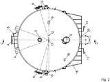
- ist eine Vorderansicht eines Wirbelschicht-Trockners.is a front view of a fluidized bed dryer.
- Fig.2Fig.2
-
ist eine Seitenansicht auf den Wirbelschicht-Trockner von links in
Figur 1 .is a side view of the fluidized bed dryer from the left inFIG. 1 , - Fig.3Figure 3
-
ist eine rückwärtige Ansicht auf den Wirbelschicht-Trockner aus
Figur 1 .is a rear view of the fluidized bed dryerFIG. 1 , - Fig.4Figure 4
-
ist ein Längsschnitt entlang der Schnittebene C-C in
Figur 2 .is a longitudinal section along the section plane CC inFIG. 2 , - Fig.5Figure 5
-
ist ein Querschnitt entlang der Schnittebene B-B in
Figur 1 .is a cross section along the section BB inFIG. 1 , - Fig.6Figure 6
-
ist ein Querschnitt entlang der Schnittebene A-A in
Figur 1 .is a cross section along the cutting plane AA inFIG. 1 ,
Die Figuren zeigen eine Wirbelschicht-Trockneranordnung. Die Anordnung wird zur Trocknung von Roh-Braunkohle verwendet. Die Wirbelschicht-Trockneranordnung umfasst einen Behälter mit einem Behältermantel 1 in einem Sattellager 18. Der Behälter ist im Wesentlichen zylindrisch ausgebildet. An den Stirnseiten ist der Behälter nach außen gewölbt. Der Behälter ist mit einer Behälterheizung 16 beheizt, welche einen Kondensatsammler 17 aufweist. Der Behälter steht unter einem Druck von 4 bar. Die Behälterheizung 16 wird aus einem Verteiler 15 mit Heizdampf gespeist.The figures show a fluidized bed dryer arrangement. The arrangement is used to dry raw lignite. The fluidized bed dryer assembly comprises a container with a
Im oberen Bereich des Behälters sind zwei Kohleeinfallschächte 2 vorgesehen. Durch die Kohleeinfallschächte 2 wird die feuchte Rohkohle in den Behälter eingeführt. Hierfür sind geeignete Schleusen, beispielsweise eine Zellenradschleuse, vorgesehen, welche das Einbringen der Kohle auch in den unter einem Druck von 4 bar stehenden Behälter ermöglichen.In the upper part of the container two
Im Bereich zwischen den Kohleeinfallschächten 2 sind zwei Brüdenabzüge 3 mit einem statischen Sichter 31 angeordnet. Über die Brüdenabzüge 3 wird mit Kohlenstaub belasteter Dampf aus dem Behälterinneren ausgelassen. Während des Anfahrprozesses der druckaufgeladenen Wirbelschichttrocknung wird Trockenbraunkohle über die Zuführung 4 in den Trockner gegeben. Trockenbraunkohle, welche aus den Brüden mittels eines Brüdenfilters gefiltert wurde, wird über eine Rückführung 5 in das Behälterinnere zurückgeführt.In the area between the
Im Bereich des Brüdenabzuges 3 wird durch einen statischen Sichter 31 ein Teil des Kohlenstaubes abgeschieden, der dann im Wirbelschichttrockner verbleibt. Somit wird der Anteil des Kohlenstaubes im abgezogenen Brüden verringert.In the area of the
Zur Wartung der Anordnung außerhalb des Betriebs bei Normaldruck ist eine Einsteigetür 6 im mittleren Bereich des Behältermantels vorgesehen. Seitlich neben der Einsteigetür 6 ist ein Rußbläser 7 zur Heizflächenreinigung während des Abfahrprozesses und zur Zerstörung von Kohleschollen vorgesehen. Der Rußbläser ist eine Reinigungseinrichtung, die während des Entleerens des Trockners, d.h. während des Abfahrvorgangs Trockenkohleablagerungen auf den Heizflächenrohren vermeidet. Der Rußbläser 7 wird mit Dampf als Reinigungsmedium betrieben. Gleichzeitig können während des Betriebes durch gezielte Dampfimpulse auftretende Schollenbildung (Kohleklumpen) auf der Wirbelschichtoberfläche zerstört werden.For maintenance of the arrangement outside the operation at atmospheric pressure, a
Ferner ist eine Spüleinrichtung 30 vorgesehen. Die Spüleinrichtung 30 ist ein Spülstutzen, mit welchem während des Entleerens des Trockners Kohleablagerungen auf dem Trocknerboden beseitigt werden.Furthermore, a
Etwas oberhalb des Behälterbodens ist ein Düsenboden 28 angeordnet. Aus den Düsen des Düsenbodens 28 tritt unter Druck stehender Dampf aus. Mit diesem Dampf wird eine Wirbelschicht aus Kohle erzeugt. Ein Teil des Fluidisierungsdampfes kann über Seitendüsen 32 im oberen Bereich der Wirbelschicht eingebracht werden, um die Turbulenzen und somit die Einmischung der feuchten Rohfeinkohle zu unterstützen.Just above the container bottom, a nozzle bottom 28 is arranged. From the nozzles of the
Die Düsen des Düsenbodens werden mit unterschiedlichen Dampfmengen beaufschlagt. In den Randbereichen des Düsenbodens tritt eine höhere Dampfmenge aus den Düsen aus als im Mittenbereich. Dadurch werden Einmischzonen im Randbereich und eine Trocknerzone im mittleren Bereich definiert. Grundsätzlich sind zu hohe Dampfmengen unwirtschaftlich. Es ist daher wünschenswert, die Wirbelschicht mit möglichst wenig Dampf zu erzeugen. Die Rohkohle hat jedoch einen hohen Wasseranteil im Bereich von beispielsweise 50-60%. Die Oberflächenfeuchte führt daher zu Verklebung. Wenn die Rohkohle aus den Kohleeinfallschächten 2 nach unten gelangt, besteht die Gefahr der Schollenbildung. Eine höhere Dampfmenge aus den Düsen des Düsenbodens 28 unterhalb der Kohleeinfallschächte 2 erhöht die Teilchengeschwindigkeit und vermeidet die Gefahr der Schollenbildung. In der Trocknerzone im Mittenbereich des Düsenbodens ist diese hohe Dampfmenge nicht erforderlich. Dort kann mit üblichen Dampfmengen gearbeitet werden. Auf diese Weise wird weiterhin mit einem Minimum an Dampf gearbeitet.The nozzles of the nozzle bottom are charged with different amounts of steam. In the edge regions of the nozzle bottom, a larger amount of steam exits the nozzles than in the middle region. This defines mixing zones in the edge area and a dryer zone in the middle area. Basically too high steam quantities are uneconomical. It is therefore desirable to produce the fluidized bed with as little steam as possible. However, the raw coal has a high water content in the range of, for example, 50-60%. The surface moisture therefore leads to bonding. If the raw coal from the
Im unteren, mittleren Bereich des Behälters oberhalb des Düsenbodens ist eine Kondensationsheizfläche 22 angeordnet. Die Kondensationsheizfläche 22 besteht aus einer Vielzahl paralleler Heizrohre gleicher Länge. Sie erstreckt sich über die gesamte Länge des im Wesentlichen zylindrischen Teiles des Behälters. Die Heizrohre werden von einer Abstützung 26 gehalten. Die Längsachse der Heizrohre verläuft von rechts nach links in
Die Heizrohre der Kondensationsheizfläche 22 sind mit einer Lochplatte 27 verschweißt. Die Lochplatte 27 ist Teil einer Trennwand zwischen der Wirbelschicht und einer seitlich angeordneten Vorkammer. Zusammen mit der Lochplatte 27 bildet eine halbkugelförmige Schale eine Eintrittskammer 21. Ausgangsseitig bildet die korrespondierende Lochplatte mit einer halbkugelförmigen Schale eine Austrittskammer 23. Die Eintrittskammer 21 ist über Verbindungsrohre 20 mit einem Heizdampfeintritt 9 verbunden. Die Eintrittskammer 21 weist einen Kondensatabfluss 25 auf. Die Austrittskammer 23 weist einen Kondensatabfluss 24 auf. Heizdampf tritt über den Heizdampfeintritt 9 und die Verbindungsrohre 20 in die Eintrittskammer 21 ein. Diese bildet einen Verteiler. Der Heizdampf tritt durch die Löcher in der Lochplatte 27 in die daran angeschweißten Heizrohre der Kondensationsheizfläche 22. Ausgangsseitig tritt das Heizdampfkondensat durch die Löcher der Lochplatte 27 in die Austrittskammer 23. Diese bildet einen Sammler. Durch den Kondensatabfluss 24 tritt Wasser, welches im Bereich der Wirbelschicht in den Heizrohren kondensiert ist, wieder aus.The heating tubes of the
Die durch den Kohleeinfallschacht 2 eintretende Kohle tritt in die Wirbelschicht ein. An der Kondensationsheizfläche wird die Wirbelschicht beheizt und getrocknet. Die Trockenbraunkohle wird über einen Verbindungsschacht 29 im Boden des Behälters zu einer Förderschnecke transportiert. Dort steht sie zur weiteren Verwendung zur Verfügung.The coal entering through the
Da seitlich der Heizrohre ausreichend Platz ist, können Eintritts- und Austrittskammer 21, bzw. 23 halbkugelförmig ausgebildet werden. Die Überwachung der Anordnung erfolgt mit Messinstrumenten. Hierzu gehören Thermoelemente, welche an Temperaturmessstellen 11 angeordnet sind und Manometer zur Messung des Drucks an Druckmesstellen 12. Eine visuelle Überwachung des Trocknungsvorgangs erfolgt über ein Schauglas 13 mit Spülstutzen.Since there is sufficient space at the side of the heating pipes, the inlet and
Die Kondensationsheizfläche 22 weist in Längsrichtung des Behälters 1 eine durchgängige, vertikale Gasse 14 auf. In ihr sind keine Heizrohre vorgesehen. Die vertikale Gasse liegt direkt unterhalb der Kohleeinfallschächte 2 im Mittenbereich des Behälters. Mit der Gasse 14 wird eine verbesserte Einmischung der Rohkohle in die Trockenkohle erreicht. Die Rohkohle wird besser verteilt und kann nicht oberhalb der Kohleschüttung der Wirbelschicht liegen bleiben. Die Kohleoberkante liegt nicht zu dicht oberhalb der Kondensationsheizfläche um eine Schollenbildung zu vermeiden. Eine Lücke im Trockenbereich führt zu einer guten Einbringung der Rohkohle.The
Claims (10)
dadurch gekennzeichnet, dass
characterized in that
Applications Claiming Priority (1)
| Application Number | Priority Date | Filing Date | Title |
|---|---|---|---|
| DE102011001031A DE102011001031A1 (en) | 2011-03-02 | 2011-03-02 | Fluidized bed dryer arrangement |
Publications (2)
| Publication Number | Publication Date |
|---|---|
| EP2495518A2 true EP2495518A2 (en) | 2012-09-05 |
| EP2495518A3 EP2495518A3 (en) | 2015-09-16 |
Family
ID=45655189
Family Applications (1)
| Application Number | Title | Priority Date | Filing Date |
|---|---|---|---|
| EP12152063.9A Withdrawn EP2495518A3 (en) | 2011-03-02 | 2012-01-23 | Fluidised bed drier system |
Country Status (2)
| Country | Link |
|---|---|
| EP (1) | EP2495518A3 (en) |
| DE (1) | DE102011001031A1 (en) |
Citations (4)
| Publication number | Priority date | Publication date | Assignee | Title |
|---|---|---|---|---|
| US2629938A (en) * | 1949-03-03 | 1953-03-03 | Kaiser Aluminium Chem Corp | Method and apparatus for treating solids |
| US3605275A (en) * | 1968-07-29 | 1971-09-20 | Struthers Wells Corp | Fluidized bed dryer |
| DE19620047C2 (en) | 1996-05-18 | 2002-06-27 | Rwe Rheinbraun Ag | Method and device for drying lignite |
| US20110247232A1 (en) * | 2009-10-08 | 2011-10-13 | The Korea Institute Of Energy Research | Fluidized bed drying apparatus |
Family Cites Families (3)
| Publication number | Priority date | Publication date | Assignee | Title |
|---|---|---|---|---|
| DE10251233A1 (en) * | 2002-11-02 | 2004-05-13 | Matthias Limburg | Solid fuel crushing, drying and feed device, designed to be quickly heated or cooled depending on impact strength of fuel |
| US8523963B2 (en) * | 2004-10-12 | 2013-09-03 | Great River Energy | Apparatus for heat treatment of particulate materials |
| KR101701693B1 (en) * | 2008-08-12 | 2017-02-13 | 슈빙 바이오셋 | Closed loop drying system and method |
-
2011
- 2011-03-02 DE DE102011001031A patent/DE102011001031A1/en not_active Withdrawn
-
2012
- 2012-01-23 EP EP12152063.9A patent/EP2495518A3/en not_active Withdrawn
Patent Citations (4)
| Publication number | Priority date | Publication date | Assignee | Title |
|---|---|---|---|---|
| US2629938A (en) * | 1949-03-03 | 1953-03-03 | Kaiser Aluminium Chem Corp | Method and apparatus for treating solids |
| US3605275A (en) * | 1968-07-29 | 1971-09-20 | Struthers Wells Corp | Fluidized bed dryer |
| DE19620047C2 (en) | 1996-05-18 | 2002-06-27 | Rwe Rheinbraun Ag | Method and device for drying lignite |
| US20110247232A1 (en) * | 2009-10-08 | 2011-10-13 | The Korea Institute Of Energy Research | Fluidized bed drying apparatus |
Also Published As
| Publication number | Publication date |
|---|---|
| DE102011001031A1 (en) | 2012-09-06 |
| EP2495518A3 (en) | 2015-09-16 |
Similar Documents
| Publication | Publication Date | Title |
|---|---|---|
| DE69728984T2 (en) | METHOD AND DEVICE FOR APPLYING A MATERIAL TO A TRACKED SUBSTRATE | |
| DE3248384C2 (en) | Device for dewatering solids | |
| DE69903196T2 (en) | DEVICE FOR TREATING A GAS / LIQUID MIXTURE | |
| DE102006009442A1 (en) | Compression screw with a combination of single and double threads | |
| WO1997046304A1 (en) | Process and device for drying gas, especially natural gas | |
| DE60217183T2 (en) | DEVICE FOR DRYING A PARTICULAR PRODUCT WITH OVERHEATED STEAM | |
| DE19620047C2 (en) | Method and device for drying lignite | |
| DE69620608T2 (en) | METHOD AND DEVICE FOR TREATING A BAD HEAT-DERIVING MATERIAL | |
| EP2495518A2 (en) | Fluidised bed drier system | |
| DE3137503A1 (en) | RELAXATION EVAPORATOR FOR GEOTHERMAL POWER PLANTS | |
| DE9114967U1 (en) | Evaporator system for the treatment of sludge | |
| EP2498034A2 (en) | Fluidised bed drier system | |
| DE3107259A1 (en) | "METHOD AND DEVICE FOR DEPOSITING VAPOR FROM MATERIAL CONTAINING WOOD FIBER FIBER" | |
| EP2495495A2 (en) | Fluidised bed drier system | |
| DE1619942A1 (en) | Method and device for degassing liquid suspensions | |
| EP2352959B1 (en) | Indirectly heated fluidized bed dryer | |
| DE102013100595A1 (en) | System useful for drying sludge, preferably e.g. digested sludge or industrial sludge, comprises a device for conveying sludge between product inlet and product outlet, where device exhibits trough in which conveying screw is arranged | |
| AT504589B1 (en) | METHOD AND DEVICE FOR REMOVING GAS FROM WOOD CHIPS | |
| WO2021209232A1 (en) | Steam blower box comprising steam conditioning | |
| EP2395306A2 (en) | Method and device for drying fibrous goods, in particular wood chips | |
| DD271944B5 (en) | INDIRECTLY HEATED STEAM WHEEL LAYER DRYING SYSTEM | |
| DE202019106564U1 (en) | Dust separator and evaporation dryer | |
| DE2512162C3 (en) | Method and device for the rapid drying of cellulose pulp | |
| AT508526B1 (en) | DEVICE AND METHOD FOR FEEDING A FIBER PULSE TO A TRAIN TRAY CARRIER | |
| DE3836004C2 (en) |
Legal Events
| Date | Code | Title | Description |
|---|---|---|---|
| PUAI | Public reference made under article 153(3) epc to a published international application that has entered the european phase |
Free format text: ORIGINAL CODE: 0009012 |
|
| AK | Designated contracting states |
Kind code of ref document: A2 Designated state(s): AL AT BE BG CH CY CZ DE DK EE ES FI FR GB GR HR HU IE IS IT LI LT LU LV MC MK MT NL NO PL PT RO RS SE SI SK SM TR |
|
| AX | Request for extension of the european patent |
Extension state: BA ME |
|
| 17P | Request for examination filed |
Effective date: 20130304 |
|
| RAP1 | Party data changed (applicant data changed or rights of an application transferred) |
Owner name: BABCOCK BORSIG STEINMUELLER GMBH |
|
| PUAL | Search report despatched |
Free format text: ORIGINAL CODE: 0009013 |
|
| AK | Designated contracting states |
Kind code of ref document: A3 Designated state(s): AL AT BE BG CH CY CZ DE DK EE ES FI FR GB GR HR HU IE IS IT LI LT LU LV MC MK MT NL NO PL PT RO RS SE SI SK SM TR |
|
| AX | Request for extension of the european patent |
Extension state: BA ME |
|
| RIC1 | Information provided on ipc code assigned before grant |
Ipc: F23K 1/04 20060101ALI20150813BHEP Ipc: F26B 3/084 20060101AFI20150813BHEP |
|
| STAA | Information on the status of an ep patent application or granted ep patent |
Free format text: STATUS: EXAMINATION IS IN PROGRESS |
|
| 17Q | First examination report despatched |
Effective date: 20180425 |
|
| STAA | Information on the status of an ep patent application or granted ep patent |
Free format text: STATUS: THE APPLICATION IS DEEMED TO BE WITHDRAWN |
|
| 18D | Application deemed to be withdrawn |
Effective date: 20190801 |