EP2495465A1 - Slide bearing - Google Patents
Slide bearing Download PDFInfo
- Publication number
- EP2495465A1 EP2495465A1 EP10826479A EP10826479A EP2495465A1 EP 2495465 A1 EP2495465 A1 EP 2495465A1 EP 10826479 A EP10826479 A EP 10826479A EP 10826479 A EP10826479 A EP 10826479A EP 2495465 A1 EP2495465 A1 EP 2495465A1
- Authority
- EP
- European Patent Office
- Prior art keywords
- foreign substance
- substance discharging
- discharging groove
- groove
- axial direction
- Prior art date
- Legal status (The legal status is an assumption and is not a legal conclusion. Google has not performed a legal analysis and makes no representation as to the accuracy of the status listed.)
- Withdrawn
Links
Images





Classifications
-
- F—MECHANICAL ENGINEERING; LIGHTING; HEATING; WEAPONS; BLASTING
- F16—ENGINEERING ELEMENTS AND UNITS; GENERAL MEASURES FOR PRODUCING AND MAINTAINING EFFECTIVE FUNCTIONING OF MACHINES OR INSTALLATIONS; THERMAL INSULATION IN GENERAL
- F16C—SHAFTS; FLEXIBLE SHAFTS; ELEMENTS OR CRANKSHAFT MECHANISMS; ROTARY BODIES OTHER THAN GEARING ELEMENTS; BEARINGS
- F16C33/00—Parts of bearings; Special methods for making bearings or parts thereof
- F16C33/02—Parts of sliding-contact bearings
- F16C33/04—Brasses; Bushes; Linings
- F16C33/06—Sliding surface mainly made of metal
- F16C33/10—Construction relative to lubrication
-
- F—MECHANICAL ENGINEERING; LIGHTING; HEATING; WEAPONS; BLASTING
- F16—ENGINEERING ELEMENTS AND UNITS; GENERAL MEASURES FOR PRODUCING AND MAINTAINING EFFECTIVE FUNCTIONING OF MACHINES OR INSTALLATIONS; THERMAL INSULATION IN GENERAL
- F16C—SHAFTS; FLEXIBLE SHAFTS; ELEMENTS OR CRANKSHAFT MECHANISMS; ROTARY BODIES OTHER THAN GEARING ELEMENTS; BEARINGS
- F16C17/00—Sliding-contact bearings for exclusively rotary movement
- F16C17/02—Sliding-contact bearings for exclusively rotary movement for radial load only
- F16C17/022—Sliding-contact bearings for exclusively rotary movement for radial load only with a pair of essentially semicircular bearing sleeves
-
- F—MECHANICAL ENGINEERING; LIGHTING; HEATING; WEAPONS; BLASTING
- F16—ENGINEERING ELEMENTS AND UNITS; GENERAL MEASURES FOR PRODUCING AND MAINTAINING EFFECTIVE FUNCTIONING OF MACHINES OR INSTALLATIONS; THERMAL INSULATION IN GENERAL
- F16C—SHAFTS; FLEXIBLE SHAFTS; ELEMENTS OR CRANKSHAFT MECHANISMS; ROTARY BODIES OTHER THAN GEARING ELEMENTS; BEARINGS
- F16C17/00—Sliding-contact bearings for exclusively rotary movement
- F16C17/12—Sliding-contact bearings for exclusively rotary movement characterised by features not related to the direction of the load
- F16C17/24—Sliding-contact bearings for exclusively rotary movement characterised by features not related to the direction of the load with devices affected by abnormal or undesired positions, e.g. for preventing overheating, for safety
- F16C17/246—Sliding-contact bearings for exclusively rotary movement characterised by features not related to the direction of the load with devices affected by abnormal or undesired positions, e.g. for preventing overheating, for safety related to wear, e.g. sensors for measuring wear
-
- F—MECHANICAL ENGINEERING; LIGHTING; HEATING; WEAPONS; BLASTING
- F16—ENGINEERING ELEMENTS AND UNITS; GENERAL MEASURES FOR PRODUCING AND MAINTAINING EFFECTIVE FUNCTIONING OF MACHINES OR INSTALLATIONS; THERMAL INSULATION IN GENERAL
- F16C—SHAFTS; FLEXIBLE SHAFTS; ELEMENTS OR CRANKSHAFT MECHANISMS; ROTARY BODIES OTHER THAN GEARING ELEMENTS; BEARINGS
- F16C33/00—Parts of bearings; Special methods for making bearings or parts thereof
- F16C33/02—Parts of sliding-contact bearings
- F16C33/04—Brasses; Bushes; Linings
- F16C33/06—Sliding surface mainly made of metal
- F16C33/08—Attachment of brasses, bushes or linings to the bearing housing
-
- F—MECHANICAL ENGINEERING; LIGHTING; HEATING; WEAPONS; BLASTING
- F16—ENGINEERING ELEMENTS AND UNITS; GENERAL MEASURES FOR PRODUCING AND MAINTAINING EFFECTIVE FUNCTIONING OF MACHINES OR INSTALLATIONS; THERMAL INSULATION IN GENERAL
- F16C—SHAFTS; FLEXIBLE SHAFTS; ELEMENTS OR CRANKSHAFT MECHANISMS; ROTARY BODIES OTHER THAN GEARING ELEMENTS; BEARINGS
- F16C33/00—Parts of bearings; Special methods for making bearings or parts thereof
- F16C33/02—Parts of sliding-contact bearings
- F16C33/04—Brasses; Bushes; Linings
- F16C33/06—Sliding surface mainly made of metal
- F16C33/10—Construction relative to lubrication
- F16C33/1025—Construction relative to lubrication with liquid, e.g. oil, as lubricant
- F16C33/1045—Details of supply of the liquid to the bearing
- F16C33/105—Conditioning, e.g. metering, cooling, filtering
-
- F—MECHANICAL ENGINEERING; LIGHTING; HEATING; WEAPONS; BLASTING
- F16—ENGINEERING ELEMENTS AND UNITS; GENERAL MEASURES FOR PRODUCING AND MAINTAINING EFFECTIVE FUNCTIONING OF MACHINES OR INSTALLATIONS; THERMAL INSULATION IN GENERAL
- F16C—SHAFTS; FLEXIBLE SHAFTS; ELEMENTS OR CRANKSHAFT MECHANISMS; ROTARY BODIES OTHER THAN GEARING ELEMENTS; BEARINGS
- F16C33/00—Parts of bearings; Special methods for making bearings or parts thereof
- F16C33/02—Parts of sliding-contact bearings
- F16C33/04—Brasses; Bushes; Linings
- F16C33/06—Sliding surface mainly made of metal
- F16C33/10—Construction relative to lubrication
- F16C33/1025—Construction relative to lubrication with liquid, e.g. oil, as lubricant
- F16C33/106—Details of distribution or circulation inside the bearings, e.g. details of the bearing surfaces to affect flow or pressure of the liquid
- F16C33/1065—Grooves on a bearing surface for distributing or collecting the liquid
-
- F—MECHANICAL ENGINEERING; LIGHTING; HEATING; WEAPONS; BLASTING
- F16—ENGINEERING ELEMENTS AND UNITS; GENERAL MEASURES FOR PRODUCING AND MAINTAINING EFFECTIVE FUNCTIONING OF MACHINES OR INSTALLATIONS; THERMAL INSULATION IN GENERAL
- F16C—SHAFTS; FLEXIBLE SHAFTS; ELEMENTS OR CRANKSHAFT MECHANISMS; ROTARY BODIES OTHER THAN GEARING ELEMENTS; BEARINGS
- F16C9/00—Bearings for crankshafts or connecting-rods; Attachment of connecting-rods
- F16C9/02—Crankshaft bearings
-
- F—MECHANICAL ENGINEERING; LIGHTING; HEATING; WEAPONS; BLASTING
- F16—ENGINEERING ELEMENTS AND UNITS; GENERAL MEASURES FOR PRODUCING AND MAINTAINING EFFECTIVE FUNCTIONING OF MACHINES OR INSTALLATIONS; THERMAL INSULATION IN GENERAL
- F16C—SHAFTS; FLEXIBLE SHAFTS; ELEMENTS OR CRANKSHAFT MECHANISMS; ROTARY BODIES OTHER THAN GEARING ELEMENTS; BEARINGS
- F16C9/00—Bearings for crankshafts or connecting-rods; Attachment of connecting-rods
- F16C9/04—Connecting-rod bearings; Attachments thereof
-
- F—MECHANICAL ENGINEERING; LIGHTING; HEATING; WEAPONS; BLASTING
- F16—ENGINEERING ELEMENTS AND UNITS; GENERAL MEASURES FOR PRODUCING AND MAINTAINING EFFECTIVE FUNCTIONING OF MACHINES OR INSTALLATIONS; THERMAL INSULATION IN GENERAL
- F16C—SHAFTS; FLEXIBLE SHAFTS; ELEMENTS OR CRANKSHAFT MECHANISMS; ROTARY BODIES OTHER THAN GEARING ELEMENTS; BEARINGS
- F16C33/00—Parts of bearings; Special methods for making bearings or parts thereof
- F16C33/02—Parts of sliding-contact bearings
- F16C33/04—Brasses; Bushes; Linings
- F16C33/046—Brasses; Bushes; Linings divided or split, e.g. half-bearings or rolled sleeves
Definitions
- the present invention relates to a sliding bearing, and more particularly, to a sliding bearing configured into a cylindrical shape with a pair of half-bearings placed so as to abut against each other.
- a sliding bearing which is configured into a cylindrical shape with a pair of half-bearings placed abutting against each other, and provided with a chamfer part and a crush relief in an inner circumferential part of each of the abutting surfaces of the half-bearings (see Figure 7 ).
- a sliding bearing provided with a crush relief as a notch, when a lubricant is supplied from an oil hole of a crank shaft as shown in Figure 7 , a foreign substance mixed in the lubricant is trapped by the crush relief and then discharged to the outside through the crush relief and openings on both sides of the chamfer part.
- a sliding bearing in which a foreign substance discharging groove is formed at a required location of the sliding surface so as to trap and discharge the foreign substance mixed in the lubricant (e.g., Patent Literature 1 to Patent Literature 4).
- a foreign substance discharging groove is formed at a required location of the sliding surface so as to trap and discharge the foreign substance mixed in the lubricant (e.g., Patent Literature 1 to Patent Literature 4).
- an oil groove is provided over the entire area in the circumferential direction of the sliding surface of the lower half-bearing and a pair of foreign substance discharging grooves are formed which are branched from the oil groove and open to both end faces in the axial direction of the half-bearing.
- the sliding bearing of Patent Literature 2 is configured such that the axis of rotation is axially supported by a plurality of arc-shaped pads, a T-shaped groove is formed on the sliding surface of each arc-shaped pad to trap a foreign substance and a magnet is set up at the bottom of the axial direction groove in the T-shaped groove. The magnet is intended to attract and trap the foreign substance in the axial direction groove. Furthermore, in the sliding bearing of Patent Literature 3, a plurality of rectilinear foreign substance discharging grooves are formed along the axial direction in the vicinity of the abutting surface of the lower half-bearing.
- an axial direction groove having a triangular cross section is provided at an inner edge of the abutting surface of the half-bearing and a circumferential direction groove is formed adjacent to the axial direction groove within a predetermined range of the sliding surface.
- the sliding bearings disclosed in aforementioned Patent Literature 1 to Patent Literature 4 have the following problems. That is, in the sliding bearing of Patent Literature 1, since the oil groove is provided over the entire area in the circumferential direction of the sliding surface of the half-bearing and the foreign substance discharging groove is branched therefrom, the foreign substance is likely to circulate in the oil groove, making it difficult for the foreign substance discharging groove to reliably trap the foreign substance, which leads to a disadvantage that the foreign substance can hardly be discharged efficiently. Furthermore, in the sliding bearing of Patent Literature 2, the T-shaped groove is formed in the center of the sliding surface of the arc-shaped pad, which results in the reduced area of the entire sliding surface, leading to a problem that the load capacity of the sliding bearing decreases.
- the present invention provides a sliding bearing which is formed into a cylindrical shape by placing abutting surfaces of an upper half-bearing and a lower half-bearing so as to abut against each other and rotatably support an axis of rotation by a sliding surface made of inner surfaces of both half-bearings, wherein a foreign substance discharging groove, an end of which is open to at least one of end faces in an axial direction, is formed on the sliding surface adjacent to an inner circumferential edge of the abutting surface of at least one of the upper and lower half-bearings by being tilted with respect to the axial direction of the sliding bearing.
- reference numeral 1 denotes a sliding bearing provided on a connecting rod (not shown).
- This sliding bearing 1 is made up of a pair of upper and lower semi-cylindrical half-bearings 11 and 12, and is configured into a cylindrical shape as a whole by causing abutting surfaces 11A and 12A of both half-bearings 11 and 12 to abut against each other.
- This sliding bearing 1 pivotably supports a crank pin 2 (axis of rotation) of the crank shaft with a sliding surface 3 which is an inner surface of both half-bearings 11 and 12.
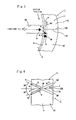
- the present embodiment provides foreign substance discharging grooves 5 and 5' in an inner circumferential edge 4 of the abutting surfaces 11A and 12A and in the sliding surface 3 adjacent thereto so that the foreign substance discharging grooves 5 and 5' may trap a foreign substance 6 mixed in the lubricant and discharge the foreign substance 6 out of the sliding surface 3. That is, as shown in Figure 2 , two rectilinear grooves are formed so as to cross each other in the sliding surface 3 adjacent to the inner circumferential edge 4 of the abutting surfaces 11A and 12A, which are one sides of the sliding bearing 1. One of the rectilinear grooves constitutes the first foreign substance discharging groove 5 and the other rectilinear groove constitutes the second foreign substance discharging groove 5'.
- both foreign substance discharging grooves 5 and 5' are set to be identical and both foreign substance discharging grooves 5 and 5' are arranged, inclined with respect to the axial direction of the sliding bearing 1 so as to cross each other at a central part 4A in the axial direction of the inner circumferential edge 4. That is, the two foreign substance discharging grooves 5 and 5' that cross each other are formed over the sliding surface 3 of the upper and lower half-bearings 11 and 12 centered on the inner circumferential edge 4.
- An end 5A of the first foreign substance discharging groove 5 on the upstream side of the rotation direction is open to one end face 8 of the upper half-bearing 11 in the axial direction and an end 5B of the foreign substance discharging groove 5 on the downstream side of the rotation direction is open to the other end face 7 of the lower half-bearing 12 (see Figure 2 and Figure 4 ).
- An end 5A' of the second foreign substance discharging groove 5' on the upstream side of the rotation direction is open to an end face 7 of the upper half-bearing 11 and an end 5B' which is the downstream side in the rotation direction of the foreign substance discharging groove 5' is open to the end face 8 of the lower half-bearing 12.
- the foreign substance discharging grooves 5 and 5' are formed such that the ends 5A and 5B (5A' and 5B') are open to the end faces 7 and 8 in the axial direction of the sliding bearing 1 via the central part 4A of the inner circumferential edge 4 in the axial direction.
- the width W and depth D of both foreign substance discharging grooves 5 and 5' are set to dimensions enough to accommodate and allow to pass the foreign substance 6 of a maximum estimated size.
- both foreign substance discharging grooves 5 and 5' have a trapezoidal cross-sectional shape with the width W being slightly greater than the depth D.
- both foreign substance discharging grooves 5 and 5' have a trapezoidal cross section which gradually expands from the bottom to the opening at the top end, right and left side walls 5C and 5C constitute inclined surfaces, inclined with respect to the neighboring sliding surface 3.
- a range ⁇ in a circumferential direction in which both foreign substance discharging grooves 5 and 5' are provided is preferably set to within a range of 25° before and after the inner circumferential edge 4 when no crush relief (notch) is set in the sliding bearing 1.
- the foreign substance discharging grooves 5 and 5' are preferably formed within crush relief regions A1 and A2 (see Figure 2 ).
- the angles of inclination of the both foreign substance discharging grooves 5 and 5' with respect to the axial direction of the sliding bearing 1 are set to 30°.
- the angles of inclination are displayed as angles formed between the peripheral edge 4 and the foreign substance discharging grooves 5 and 5' on the assumption that the inner circumferential edge 4 of the abutting surfaces 11A and 12A is parallel to the axial direction of the sliding bearing 1. Furthermore, the central part 4A of the inner circumferential edge 4 in the axial direction in the sliding bearing 1 is located on the moving track of the distal end of the lubricant supply hole 2A when the crank pin 2 rotates.
- both foreign substance discharging grooves 5 and 5' are provided inclined with respect to the axial direction of the sliding bearing 1, a downward flow of the lubricant is generated in the foreign substance discharging grooves 5 and 5'.
- the present embodiment can provide the sliding bearing 1 having better foreign substance discharging characteristics compared with the prior arts.
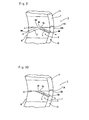
- Figure 8 shows a second embodiment of the present invention and this second embodiment omits one foreign substance discharging groove 5' in the first embodiment and provides only the other foreign substance discharging groove 5 on the sliding surface 3.
- the rest of the configuration is the same as that of the first embodiment and components corresponding to those in the first embodiment are assigned the same reference numerals.
- Such a second embodiment can also obtain operations and effects similar to those in the aforementioned first embodiment.
- Figure 9 shows a third embodiment of the present invention and this third embodiment omits the groove of the sliding surface 3 above the inner circumferential edge 4 in the foreign substance discharging grooves 5 and 5' of the first embodiment and provides a rectilinear groove below the inner circumferential edge 4 on the sliding surface 3. That is, the first foreign substance discharging groove 5 is formed from the central part 4A of the inner circumferential edge 4 in the axial direction to the one end face 7, and the second foreign substance discharging groove 5' is formed from the central part 4A of the inner circumferential edge in the axial direction to the other end face 8.
- One ends 5A and 5A' of both foreign substance discharging grooves 5 and 5' communicate with each other at the central part 4A of the inner circumferential edge 4 in the axial direction, the other end of the first foreign substance discharging groove 5 is open to the end face 7 of the lower half-bearing 12 and the other end of the second foreign substance discharging groove 5' is open to the end face 8 of the lower half-bearing 12.
- the rest of the configuration is the same as that of the first embodiment and components corresponding to those in the first embodiment are assigned the same reference numerals.
- Such a third embodiment can also obtain operations and effects similar to those in the aforementioned first embodiment.
- Figure 10 shows a fourth embodiment of the present invention and this fourth embodiment omits the one foreign substance discharging groove 5' in the third embodiment in Figure 9 and provides a single foreign substance discharging groove 5 on the sliding surface 3 of the lower half-bearing 12. That is, in this fourth embodiment, the foreign substance discharging groove 5 is formed from the central part 4A of the inner circumferential edge 4 in the axial direction to the end face 7. The rest of the configuration is the same as that of the first embodiment.
- Such a fourth embodiment can also obtain operations and effects similar to those in the aforementioned first embodiment.
- Figure 11 shows a fifth embodiment of the present invention and in this fifth embodiment, the foreign substance discharging groove 5 at the central part 4A of the inner circumferential edge 4 has a greater width than the width of the ends 5A and 5B in the second embodiment shown in Figure 8 .
- the width of the foreign substance discharging groove 5 at the central part 4A is approximately 1.5 times that of the foreign substance discharging groove 5 at the ends 5A and 5B and the width of the foreign substance discharging groove 5 gradually decreases from the position of the central part 4A toward both ends 5A and 5B.
- the foreign substance discharging groove 5 (5') is set to the same depth over the entire area. The rest of the configuration is the same as that of the second embodiment shown in Figure 8 .
- Such a fifth embodiment can also obtain operations and effects similar to those in the aforementioned embodiments.
- Figure 12 shows a sixth embodiment of the present invention and in this sixth embodiment, the depth of the foreign substance discharging groove 5 at the central part 4A of the inner circumferential edge 4 is greater than the depth at the ends 5A and 5B in the second embodiment shown in Figure 8 .
- the depth of the foreign substance discharging groove 5 at the central part 4A is approximately 1.5 times the depth of the foreign substance discharging groove 5 at the ends 5A and 5B and the depth of the foreign substance discharging groove 5 gradually decreases from the position of the central part 4A toward the ends 5A and 5B.
- the foreign substance discharging groove 5 is set to the same width throughout the entire area. The rest of the configuration is the same as that of the second embodiment shown in Figure 8 .
- Such a sixth embodiment can also obtain operations and effects similar to those in the aforementioned embodiments.
- the aforementioned fifth embodiment and sixth embodiment may be combined, that is, in the second embodiment shown in Figure 8 , the width of the foreign substance discharging groove 5 at the central part 4A of the inner circumferential edge 4 may be greater than that at the ends 5A and 5B and the depth may be greater than at the ends 5A and 5B.
- Figure 13 shows a seventh embodiment of the present invention, and this seventh embodiment provides a curved foreign substance discharging groove 5 instead of the rectilinear foreign substance discharging groove 5 in the second embodiment in Figure 8 above and the width of the foreign substance discharging groove 5 at the central part 4A of the inner circumferential edge 4 is greater than that at the ends 5A and 5R.
- the foreign substance discharging groove 5 is set to the same depth throughout the entire area. The rest of the configuration is the same as that of the second embodiment shown in Figure 8 .
- Such a seventh embodiment can also obtain operations and effects similar to those in the aforementioned embodiments.
- the foreign substance discharging grooves 5 and 5' of the aforementioned present embodiments can be formed on the sliding surface 3 of the sliding bearing 1 irrespective of whether or not the chamfer part is formed at the inner circumferential edge 4 of the abutting surfaces 11A and 12B.
- the foreign substance discharging groove 5 (5') sufficiently secures the discharging path of the foreign substance, and therefore minimizing the amount of chamfering of the sliding bearing 1 is considered preferable from the standpoint of securing a hydraulic pressure of the engine.
Landscapes
- Engineering & Computer Science (AREA)
- General Engineering & Computer Science (AREA)
- Mechanical Engineering (AREA)
- Chemical & Material Sciences (AREA)
- Oil, Petroleum & Natural Gas (AREA)
- Sliding-Contact Bearings (AREA)
- Shafts, Cranks, Connecting Bars, And Related Bearings (AREA)
Abstract
Description
- The present invention relates to a sliding bearing, and more particularly, to a sliding bearing configured into a cylindrical shape with a pair of half-bearings placed so as to abut against each other.
- Conventionally, a sliding bearing is known which is configured into a cylindrical shape with a pair of half-bearings placed abutting against each other, and provided with a chamfer part and a crush relief in an inner circumferential part of each of the abutting surfaces of the half-bearings (see
Figure 7 ). In such a sliding bearing provided with a crush relief as a notch, when a lubricant is supplied from an oil hole of a crank shaft as shown inFigure 7 , a foreign substance mixed in the lubricant is trapped by the crush relief and then discharged to the outside through the crush relief and openings on both sides of the chamfer part.
Conventionally, a sliding bearing is proposed in which a foreign substance discharging groove is formed at a required location of the sliding surface so as to trap and discharge the foreign substance mixed in the lubricant (e.g.,Patent Literature 1 to Patent Literature 4).
In the sliding bearing ofPatent Literature 1, an oil groove is provided over the entire area in the circumferential direction of the sliding surface of the lower half-bearing and a pair of foreign substance discharging grooves are formed which are branched from the oil groove and open to both end faces in the axial direction of the half-bearing.
Furthermore, the sliding bearing ofPatent Literature 2 is configured such that the axis of rotation is axially supported by a plurality of arc-shaped pads, a T-shaped groove is formed on the sliding surface of each arc-shaped pad to trap a foreign substance and a magnet is set up at the bottom of the axial direction groove in the T-shaped groove. The magnet is intended to attract and trap the foreign substance in the axial direction groove.
Furthermore, in the sliding bearing ofPatent Literature 3, a plurality of rectilinear foreign substance discharging grooves are formed along the axial direction in the vicinity of the abutting surface of the lower half-bearing.
Furthermore, in the sliding bearing ofPatent Literature 4, an axial direction groove having a triangular cross section is provided at an inner edge of the abutting surface of the half-bearing and a circumferential direction groove is formed adjacent to the axial direction groove within a predetermined range of the sliding surface. -
- Patent Literature 1: Japanese Utility Model Laid-Open No.
02-116028 - Patent Literature 2: Japanese Utility Model Laid-Open No.
58-046805 - Patent Literature 3: Japanese Patent Laid-Open No.
5-202936 - Patent Literature 4: Japanese Patent Laid-Open No.
2009-174697 - However, the sliding bearings disclosed in
aforementioned Patent Literature 1 toPatent Literature 4 have the following problems.
That is, in the sliding bearing ofPatent Literature 1, since the oil groove is provided over the entire area in the circumferential direction of the sliding surface of the half-bearing and the foreign substance discharging groove is branched therefrom, the foreign substance is likely to circulate in the oil groove, making it difficult for the foreign substance discharging groove to reliably trap the foreign substance, which leads to a disadvantage that the foreign substance can hardly be discharged efficiently.
Furthermore, in the sliding bearing ofPatent Literature 2, the T-shaped groove is formed in the center of the sliding surface of the arc-shaped pad, which results in the reduced area of the entire sliding surface, leading to a problem that the load capacity of the sliding bearing decreases.
Furthermore, in the sliding bearing ofPatent Literature 3, a plurality of axial direction grooves for discharging a foreign substance are only formed in the lower half-bearing on which a load is imposed, resulting in a disadvantage that the foreign substance can hardly be discharged efficiently.
Furthermore, in the sliding bearing ofPatent Literature 4, the foreign substance trapped by the circumferential direction groove is discharged via the axial direction groove, resulting in a disadvantage that the foreign substance can hardly be discharged efficiently. - In view of the aforementioned circumstances, the present invention provides a sliding bearing which is formed into a cylindrical shape by placing abutting surfaces of an upper half-bearing and a lower half-bearing so as to abut against each other and rotatably support an axis of rotation by a sliding surface made of inner surfaces of both half-bearings, wherein a foreign substance discharging groove, an end of which is open to at least one of end faces in an axial direction, is formed on the sliding surface adjacent to an inner circumferential edge of the abutting surface of at least one of the upper and lower half-bearings by being tilted with respect to the axial direction of the sliding bearing.
- In such a configuration, foreign substances included in the lubricant are trapped in the above-described foreign substance discharging groove and discharged out of the sliding bearing via the tilted foreign substance discharging groove as the axis of rotation rotates. Therefore, it is possible to provide a sliding bearing of better foreign substance discharging characteristics compared to the prior arts.
-
- [
Figure 1] Figure 1 is a cross-sectional view of a sliding bearing and a crank pin illustrating an embodiment of the present invention. - [
Figure 2] Figure 2 is an enlarged perspective view of main parts on one side of the sliding bearing shown inFigure 1 . - [
Figure 3] Figure 3 is a schematic view illustrating a state in which a lubricant containing a foreign substance is supplied to the main parts inFigure 1 . - [
Figure 4] Figure 4 is a front view of the main parts illustrating a range of setting the foreign substance discharging groove shown inFigure 2 . - [
Figure 5] Figure 5 is a diagram illustrating the setting range in the circumferential direction of the foreign substance discharging groove shown inFigure 2 . - [
Figure 6] Figure 6 is a cross-sectional view of the main parts along line VI-VI inFigure 4 . - [
Figure 7] Figure 7 is a front view illustrating main parts of a conventional sliding bearing. - [
Figure 8] Figure 8 is a perspective view of main parts illustrating a second embodiment of the present invention. - [
Figure 9] Figure 9 is a perspective view of main parts illustrating a third embodiment of the present invention. - [
Figure 10] Figure 10 is a perspective view of main parts illustrating a fourth embodiment of the present invention. - [
Figure 11] Figure 11 is a perspective view of main parts illustrating a fifth embodiment of the present invention. - [
Figure 12] Figure 12 is a perspective view of main parts illustrating a sixth embodiment of the present invention. - [
Figure 13] Figure 13 is a perspective view of main parts illustrating a seventh embodiment of the present invention. - Hereinafter, the present invention will be described with embodiments illustrated in the accompanying drawings. In
Figure 1 and Figure 2 ,reference numeral 1 denotes a sliding bearing provided on a connecting rod (not shown). This sliding bearing 1 is made up of a pair of upper and lower semi-cylindrical half-bearings surfaces bearings surface 3 which is an inner surface of both half-bearings
When a lubricant is discharged from an oil pump (not shown) to the crank shaft, the lubricant is supplied into a lubricant passage (not shown) provided in the crank shaft and alubricant supply hole 2A of thecrank pin 2 connected thereto. The lubricant supplied into thislubricant supply hole 2A is supplied to the slidingsurface 3 which is the inner surface of both half-bearings crank pin 2 rotates in a direction shown by an arrow (clockwise direction inFigure 1 ). This causes the slidingsurface 3 of the sliding bearing 1 to be lubricated. - The present embodiment provides foreign
substance discharging grooves 5 and 5' in an innercircumferential edge 4 of theabutting surfaces surface 3 adjacent thereto so that the foreignsubstance discharging grooves 5 and 5' may trap aforeign substance 6 mixed in the lubricant and discharge theforeign substance 6 out of the slidingsurface 3.
That is, as shown inFigure 2 , two rectilinear grooves are formed so as to cross each other in thesliding surface 3 adjacent to the innercircumferential edge 4 of theabutting surfaces substance discharging groove 5 and the other rectilinear groove constitutes the second foreign substance discharging groove 5'. - The widths and depths of both foreign
substance discharging grooves 5 and 5' are set to be identical and both foreignsubstance discharging grooves 5 and 5' are arranged, inclined with respect to the axial direction of the sliding bearing 1 so as to cross each other at acentral part 4A in the axial direction of the innercircumferential edge 4. That is, the two foreignsubstance discharging grooves 5 and 5' that cross each other are formed over the slidingsurface 3 of the upper and lower half-bearings circumferential edge 4.
Anend 5A of the first foreignsubstance discharging groove 5 on the upstream side of the rotation direction is open to oneend face 8 of the upper half-bearing 11 in the axial direction and anend 5B of the foreignsubstance discharging groove 5 on the downstream side of the rotation direction is open to theother end face 7 of the lower half-bearing 12 (seeFigure 2 andFigure 4 ). Anend 5A' of the second foreign substance discharging groove 5' on the upstream side of the rotation direction is open to anend face 7 of the upper half-bearing 11 and anend 5B' which is the downstream side in the rotation direction of the foreign substance discharging groove 5' is open to theend face 8 of the lower half-bearing 12.
Thus, the foreignsubstance discharging grooves 5 and 5' are formed such that theends central part 4A of the innercircumferential edge 4 in the axial direction. The width W and depth D of both foreignsubstance discharging grooves 5 and 5' are set to dimensions enough to accommodate and allow to pass theforeign substance 6 of a maximum estimated size. As shown in an enlarged view inFigure 6 , both foreignsubstance discharging grooves 5 and 5' have a trapezoidal cross-sectional shape with the width W being slightly greater than the depth D. Furthermore, as shown in thisFigure 6 , since both foreignsubstance discharging grooves 5 and 5' have a trapezoidal cross section which gradually expands from the bottom to the opening at the top end, right andleft side walls surface 3. - Furthermore, as shown in
Figure 5 , a range β in a circumferential direction in which both foreignsubstance discharging grooves 5 and 5' are provided is preferably set to within a range of 25° before and after the innercircumferential edge 4 when no crush relief (notch) is set in the sliding bearing 1. On the other hand, when a crush relief is set in the sliding bearing 1, the foreignsubstance discharging grooves 5 and 5' are preferably formed within crush relief regions A1 and A2 (seeFigure 2 ).
Furthermore, as shown inFigure 4 , the angles of inclination of the both foreignsubstance discharging grooves 5 and 5' with respect to the axial direction of the sliding bearing 1 are set to 30°. InFigure 4 , the angles of inclination are displayed as angles formed between theperipheral edge 4 and the foreignsubstance discharging grooves 5 and 5' on the assumption that the innercircumferential edge 4 of theabutting surfaces bearing 1.
Furthermore, thecentral part 4A of the innercircumferential edge 4 in the axial direction in the slidingbearing 1 is located on the moving track of the distal end of thelubricant supply hole 2A when thecrank pin 2 rotates. Therefore, when thecrank pin 2 rotates in the direction indicated by the arrow, the lubricant is directly supplied to thecentral part 4A of the innercircumferential edge 4 which is a point of intersection between both foreignsubstance discharging grooves 5 and 5' via thelubricant supply hole 2A. When theforeign substance 6 is mixed in the supplied lubricant, theforeign substance 6 is trapped by any one of the foreignsubstance discharging grooves 5 and 5' (seeFigure 3 ). - With the sliding
bearing 1 configured as shown above, when thecrank pin 2 is rotated in the arrow direction inFigure 1 , the lubricant is also directly supplied to the foreignsubstance discharging grooves 5 and 5' from thelubricant supply hole 2A, and the lubricant is then discharged out of both end faces 7 and 8 via the foreignsubstance discharging grooves 5 and 5'.
When the lubricant is supplied in this way, if theforeign substance 6 is included in the lubricant as shown in the schematic view inFigure 3 , theforeign substance 6 is trapped at the point of intersection of both foreignsubstance discharging grooves 5 and 5', passes through one of the foreignsubstance discharging grooves 5 and 5' and is discharged out of the slidingbearing 1 from theend end face substance discharging grooves 5 and 5' are provided inclined with respect to the axial direction of the slidingbearing 1, a downward flow of the lubricant is generated in the foreignsubstance discharging grooves 5 and 5'. Thus, theforeign substance 6 in the foreignsubstance discharging grooves 5 and 5' is guided by theside walls crank pin 2 rotates and is speedily and efficiently discharged out of the slidingbearing 1.
Therefore, the present embodiment can provide the slidingbearing 1 having better foreign substance discharging characteristics compared with the prior arts. - Next,
Figure 8 shows a second embodiment of the present invention and this second embodiment omits one foreign substance discharging groove 5' in the first embodiment and provides only the other foreignsubstance discharging groove 5 on the slidingsurface 3. The rest of the configuration is the same as that of the first embodiment and components corresponding to those in the first embodiment are assigned the same reference numerals.
Such a second embodiment can also obtain operations and effects similar to those in the aforementioned first embodiment. - Next,
Figure 9 shows a third embodiment of the present invention and this third embodiment omits the groove of the slidingsurface 3 above the innercircumferential edge 4 in the foreignsubstance discharging grooves 5 and 5' of the first embodiment and provides a rectilinear groove below the innercircumferential edge 4 on the slidingsurface 3. That is, the first foreignsubstance discharging groove 5 is formed from thecentral part 4A of the innercircumferential edge 4 in the axial direction to the oneend face 7, and the second foreign substance discharging groove 5' is formed from thecentral part 4A of the inner circumferential edge in the axial direction to theother end face 8. One ends 5A and 5A' of both foreignsubstance discharging grooves 5 and 5' communicate with each other at thecentral part 4A of the innercircumferential edge 4 in the axial direction, the other end of the first foreignsubstance discharging groove 5 is open to theend face 7 of the lower half-bearing 12 and the other end of the second foreign substance discharging groove 5' is open to theend face 8 of the lower half-bearing 12.
The rest of the configuration is the same as that of the first embodiment and components corresponding to those in the first embodiment are assigned the same reference numerals. Such a third embodiment can also obtain operations and effects similar to those in the aforementioned first embodiment. - Next,
Figure 10 shows a fourth embodiment of the present invention and this fourth embodiment omits the one foreign substance discharging groove 5' in the third embodiment inFigure 9 and provides a single foreignsubstance discharging groove 5 on the slidingsurface 3 of the lower half-bearing 12. That is, in this fourth embodiment, the foreignsubstance discharging groove 5 is formed from thecentral part 4A of the innercircumferential edge 4 in the axial direction to theend face 7. The rest of the configuration is the same as that of the first embodiment. Such a fourth embodiment can also obtain operations and effects similar to those in the aforementioned first embodiment. - Next,
Figure 11 shows a fifth embodiment of the present invention and in this fifth embodiment, the foreignsubstance discharging groove 5 at thecentral part 4A of the innercircumferential edge 4 has a greater width than the width of theends Figure 8 . To be more specific, the width of the foreignsubstance discharging groove 5 at thecentral part 4A is approximately 1.5 times that of the foreignsubstance discharging groove 5 at theends substance discharging groove 5 gradually decreases from the position of thecentral part 4A toward both ends 5A and 5B. In the above-described first embodiment to this fifth embodiment, the foreign substance discharging groove 5 (5') is set to the same depth over the entire area.
The rest of the configuration is the same as that of the second embodiment shown inFigure 8 . Such a fifth embodiment can also obtain operations and effects similar to those in the aforementioned embodiments. - Next,
Figure 12 shows a sixth embodiment of the present invention and in this sixth embodiment, the depth of the foreignsubstance discharging groove 5 at thecentral part 4A of the innercircumferential edge 4 is greater than the depth at theends Figure 8 . To be more specific, the depth of the foreignsubstance discharging groove 5 at thecentral part 4A is approximately 1.5 times the depth of the foreignsubstance discharging groove 5 at theends substance discharging groove 5 gradually decreases from the position of thecentral part 4A toward theends substance discharging groove 5 is set to the same width throughout the entire area.
The rest of the configuration is the same as that of the second embodiment shown inFigure 8 . Such a sixth embodiment can also obtain operations and effects similar to those in the aforementioned embodiments.
Though not shown, the aforementioned fifth embodiment and sixth embodiment may be combined, that is, in the second embodiment shown inFigure 8 , the width of the foreignsubstance discharging groove 5 at thecentral part 4A of the innercircumferential edge 4 may be greater than that at theends ends - Next,
Figure 13 shows a seventh embodiment of the present invention, and this seventh embodiment provides a curved foreignsubstance discharging groove 5 instead of the rectilinear foreignsubstance discharging groove 5 in the second embodiment inFigure 8 above and the width of the foreignsubstance discharging groove 5 at thecentral part 4A of the innercircumferential edge 4 is greater than that at theends 5A and 5R. In this seventh embodiment, the foreignsubstance discharging groove 5 is set to the same depth throughout the entire area.
The rest of the configuration is the same as that of the second embodiment shown inFigure 8 . Such a seventh embodiment can also obtain operations and effects similar to those in the aforementioned embodiments. - Cases have been described in the aforementioned embodiments where the foreign substance discharging groove 5 (5') is provided in the sliding
bearing 1 with no crush relief on the slidingsurface 3 adjacent to the innercircumferential edge 4 of the abuttingsurfaces 11A and 12B, but it goes without saying that the foreign substance discharging groove 5 (5') shown in the aforementioned embodiments may also be provided on the slidingbearing 1 with a crush relief on the slidingsurface 3 adjacent to the innercircumferential edge 4 of the abuttingsurfaces 11A and 12B.
Furthermore, although the above-described embodiments do not particularly refer to the chamfer part of the innercircumferential edge 4 of the abuttingsurfaces 11A and 12B, the foreignsubstance discharging grooves 5 and 5' of the aforementioned present embodiments can be formed on the slidingsurface 3 of the slidingbearing 1 irrespective of whether or not the chamfer part is formed at the innercircumferential edge 4 of the abuttingsurfaces 11A and 12B.
When the chamfer part is formed at the innercircumferential edge 4, the foreign substance discharging groove 5 (5') sufficiently secures the discharging path of the foreign substance, and therefore minimizing the amount of chamfering of the slidingbearing 1 is considered preferable from the standpoint of securing a hydraulic pressure of the engine.
Furthermore, a case has been described in the aforementioned embodiments where the foreign substance discharging groove 5 (5') is provided at the location of the innercircumferential edge 4 on one side (right side) inFigure 1 , but it goes without saying that the same foreign substance discharging groove 5 (5') as that in the aforementioned embodiments may also be provided at the innercircumferential edge 4 on the other side (left side) inFigure 1 . However, in that case, it is important to set the foreign substance discharging groove 5 (5') on the other side (left side) so that the same setting as that on one side (right side) in a forementionedFigure 1 is set with respect to the rotation direction of the axis of rotation. -
- 1
- sliding bearing
- 2
- crank pin (axis of rotation)
- 3
- sliding surface
- 4
- inner circumferential edge
- 5, 5'
- foreign substance discharging groove
- 6
- foreign substance
- 7, 8
- end face
- 11
- half-bearing
- 11A
- abutting surface
- 12
- half-bearing
- 12A
- abutting surface
Claims (10)
- A sliding bearing formed into a cylindrical shape by placing abutting surfaces of an upper half-bearing and a lower half-bearing so as to abut against each other and rotatably support an axis of rotation by a sliding surface made of inner surfaces of both half-bearings,
wherein a foreign substance discharging groove, an end of which is open to at least one of end faces in an axial direction, is formed on the sliding surface adjacent to an inner circumferential edge of the abutting surface of at least one of the upper and lower half-bearings by being tilted with respect to the axial direction of the sliding bearing. - The sliding bearing according to claim 1,
wherein the foreign substance discharging groove comprises a rectilinear first foreign substance discharging groove and a rectilinear second foreign substance discharging groove that cross each other,
the first foreign substance discharging groove crosses a central part of the inner circumferential edge in the axial direction and is provided so that both ends are open to one end face and the other end face of the sliding bearing in the axial direction, and
the second foreign substance discharging groove crosses the first foreign substance discharging groove at the central part of the inner circumferential edge in the axial direction and both ends are open to one end face and the other end face of the sliding bearing in the axial direction. - The sliding bearing according to claim 1, wherein the foreign substance discharging groove crosses the central part of the inner circumferential edge in the axial direction and comprises a rectilinear groove provided so that both ends thereof are open to one end face and the other end face of the sliding bearing in the axial direction.
- The sliding bearing according to claim 1,
wherein the foreign substance discharging groove comprises a first foreign substance discharging groove and a second foreign substance discharging groove formed on the half-bearing on the downstream side of the axis of rotation in the rotation direction,
one end of the first foreign substance discharging groove is connected to the central part of the inner circumferential edge in the axial direction and the other end comprises a rectilinear groove that is open to one end face in the axial direction,
one end of the second foreign substance discharging groove is connected to the central part of the inner circumferential edge in the axial direction and the other end comprises a rectilinear groove that is open to the other end face in the axial direction, and
the first foreign substance discharging groove and the second foreign substance discharging groove communicate with each other. - The sliding bearing according to claim 1,
wherein the foreign substance discharging groove comprises a rectilinear groove formed in the half-bearing on the downstream side of the axis of rotation in the rotation direction,
one end of the foreign substance discharging groove is connected to the central part of the inner circumferential edge in the axial direction and the other end is open to one end face in the axial direction. - The sliding bearing according to claim 3, wherein the width of the groove in the foreign substance discharging groove at the central part of the inner circumferential edge is greater than the width of the groove at the ends open to both end faces.
- The sliding bearing according to claim 3 or 6, wherein the depth of the groove in the foreign substance discharging groove at the central part of the inner circumferential edge is greater than the depth of the groove at the ends open to both end faces.
- The sliding bearing according to claim 1, wherein the foreign substance discharging groove crosses the central part of the inner circumferential edge in the axial direction and comprises a curved groove provided so that both ends thereof are open to one end face and the other end face in the axial direction.
- The sliding bearing according to any one of claims 1 to 8, wherein a crush relief made up of a notch is formed on the sliding surface adjacent to the inner circumferential edge and the foreign substance discharging groove is provided within an area in which the crush relief is formed.
- The sliding bearing according to any one of claims 1 to 8, wherein the foreign substance discharging groove is formed on the sliding surface adjacent to the inner circumferential edge within a range of 25° in a circumferential direction.
Applications Claiming Priority (2)
| Application Number | Priority Date | Filing Date | Title |
|---|---|---|---|
| JP2009250984A JP2011094746A (en) | 2009-10-30 | 2009-10-30 | Slide bearing |
| PCT/JP2010/067363 WO2011052345A1 (en) | 2009-10-30 | 2010-10-04 | Slide bearing |
Publications (2)
| Publication Number | Publication Date |
|---|---|
| EP2495465A1 true EP2495465A1 (en) | 2012-09-05 |
| EP2495465A4 EP2495465A4 (en) | 2013-07-17 |
Family
ID=43921772
Family Applications (1)
| Application Number | Title | Priority Date | Filing Date |
|---|---|---|---|
| EP10826479.7A Withdrawn EP2495465A4 (en) | 2009-10-30 | 2010-10-04 | SMOOTH BEARING |
Country Status (6)
| Country | Link |
|---|---|
| US (1) | US8616774B2 (en) |
| EP (1) | EP2495465A4 (en) |
| JP (1) | JP2011094746A (en) |
| KR (1) | KR20120063546A (en) |
| CN (1) | CN102597553A (en) |
| WO (1) | WO2011052345A1 (en) |
Cited By (1)
| Publication number | Priority date | Publication date | Assignee | Title |
|---|---|---|---|---|
| EP3176463A1 (en) * | 2015-03-05 | 2017-06-07 | Roller Bearing Company of America, Inc. | Rotation rod assembly with self lubricating liner or grooved bushings |
Families Citing this family (11)
| Publication number | Priority date | Publication date | Assignee | Title |
|---|---|---|---|---|
| JP5722758B2 (en) * | 2011-12-16 | 2015-05-27 | 大同メタル工業株式会社 | Main bearing for crankshaft of internal combustion engine |
| JP2014119080A (en) * | 2012-12-19 | 2014-06-30 | Hitachi Ltd | Slide bearing device |
| CN104019132A (en) * | 2014-05-16 | 2014-09-03 | 铜陵和武机械制造有限责任公司 | Bush |
| KR101816462B1 (en) * | 2014-07-11 | 2018-01-08 | 도시바 기카이 가부시키가이샤 | Industrial machine provided with foreign matter expulsion mechanism |
| JP6314103B2 (en) * | 2015-02-27 | 2018-04-18 | 大豊工業株式会社 | Plain bearing |
| JP6433393B2 (en) * | 2015-09-02 | 2018-12-05 | 大豊工業株式会社 | Bearing and manufacturing method thereof |
| CN106089984B (en) * | 2016-08-31 | 2019-10-25 | 樊勇 | A kind of bush(ing) bearing pair recycled from blowdown from cloth lubricating oil film |
| US10233970B2 (en) * | 2017-01-10 | 2019-03-19 | GM Global Technology Operations LLC | Journal bearings with surface features for improved bearing oil supply |
| USD906255S1 (en) * | 2017-02-23 | 2020-12-29 | Taiho Kogyo Co., Ltd. | Bushing |
| KR20190057533A (en) * | 2017-11-20 | 2019-05-29 | 두산공작기계 주식회사 | Sliding bearing for a machine tool |
| JP7749968B2 (en) * | 2021-07-30 | 2025-10-07 | マックス株式会社 | stapler |
Family Cites Families (19)
| Publication number | Priority date | Publication date | Assignee | Title |
|---|---|---|---|---|
| JPS5846805A (en) | 1981-09-14 | 1983-03-18 | 株式会社高岳製作所 | Method of increasing substation |
| JPS5846805U (en) | 1981-09-25 | 1983-03-29 | 株式会社東芝 | Pad type journal bearing |
| JPH02116028A (en) | 1988-10-24 | 1990-04-27 | Matsushita Electric Ind Co Ltd | Method for manufacturing magnetic recording media |
| JPH02116028U (en) | 1989-03-06 | 1990-09-17 | ||
| JP2970171B2 (en) * | 1992-01-24 | 1999-11-02 | トヨタ自動車株式会社 | Plain bearing |
| JPH09144750A (en) * | 1995-11-24 | 1997-06-03 | Kobe Steel Ltd | Pad type journal bearing |
| JP2000337360A (en) * | 1999-05-26 | 2000-12-05 | Mitsubishi Heavy Ind Ltd | Journal bearing |
| CA2311096C (en) * | 2000-06-02 | 2010-02-16 | Peter T. Markovitch | Bearing and bushing assembly |
| JP2002286027A (en) * | 2001-03-27 | 2002-10-03 | Mitsubishi Materials Corp | Hydrodynamic bearing |
| US6557176B2 (en) * | 2001-07-30 | 2003-05-06 | Ana F. Franco-Sion | Weight vest |
| US6626577B1 (en) * | 2002-04-05 | 2003-09-30 | Sunonwealth Electric Machine Industry Co., Ltd. | Radially inner surface structure of a bearing |
| JP4217129B2 (en) * | 2003-08-20 | 2009-01-28 | トヨタ自動車株式会社 | Crank bearing |
| JP4466020B2 (en) * | 2003-08-29 | 2010-05-26 | 大豊工業株式会社 | Plain bearing |
| JP4589086B2 (en) * | 2004-11-19 | 2010-12-01 | トヨタ自動車株式会社 | Plain bearing |
| JP2006258194A (en) * | 2005-03-17 | 2006-09-28 | Hino Motors Ltd | Piston support lubrication structure |
| KR101057306B1 (en) * | 2006-03-29 | 2011-08-16 | 히다치 훈마츠 야킨 가부시키가이샤 | Sliding bearing |
| DE102008063760B4 (en) * | 2007-12-28 | 2016-05-19 | Daido Metal Company Ltd. | Connecting rod bearings for internal combustion engines |
| JP4612072B2 (en) | 2007-12-28 | 2011-01-12 | 大同メタル工業株式会社 | Connecting rod bearing for internal combustion engine |
| JP5578308B2 (en) * | 2009-07-29 | 2014-08-27 | 大豊工業株式会社 | Plain bearing |
-
2009
- 2009-10-30 JP JP2009250984A patent/JP2011094746A/en active Pending
-
2010
- 2010-10-04 US US13/502,631 patent/US8616774B2/en not_active Expired - Fee Related
- 2010-10-04 EP EP10826479.7A patent/EP2495465A4/en not_active Withdrawn
- 2010-10-04 KR KR1020127011356A patent/KR20120063546A/en not_active Ceased
- 2010-10-04 CN CN2010800486039A patent/CN102597553A/en active Pending
- 2010-10-04 WO PCT/JP2010/067363 patent/WO2011052345A1/en not_active Ceased
Cited By (2)
| Publication number | Priority date | Publication date | Assignee | Title |
|---|---|---|---|---|
| EP3176463A1 (en) * | 2015-03-05 | 2017-06-07 | Roller Bearing Company of America, Inc. | Rotation rod assembly with self lubricating liner or grooved bushings |
| US9841048B2 (en) | 2015-03-05 | 2017-12-12 | Roller Bearing Company Of America, Inc. | Rotation rod assembly with self lubricating liner or grooved bushings |
Also Published As
| Publication number | Publication date |
|---|---|
| KR20120063546A (en) | 2012-06-15 |
| US20120201485A1 (en) | 2012-08-09 |
| EP2495465A4 (en) | 2013-07-17 |
| US8616774B2 (en) | 2013-12-31 |
| CN102597553A (en) | 2012-07-18 |
| WO2011052345A1 (en) | 2011-05-05 |
| JP2011094746A (en) | 2011-05-12 |
Similar Documents
| Publication | Publication Date | Title |
|---|---|---|
| EP2495465A1 (en) | Slide bearing | |
| EP2461055B1 (en) | Sliding bearing | |
| EP2631500B1 (en) | Bearing apparatus for crankshaft of internal combustion engine | |
| KR101196848B1 (en) | Connecting rod bearing of internal combustion engine | |
| US20130343682A1 (en) | Sliding bearing shell comprising a collecting groove | |
| US20120304957A1 (en) | Bearing oil feed device | |
| EP2604873B1 (en) | Main bearing for crankshaft for internal combustion engine | |
| JP2010286088A (en) | Sliding bearings for internal combustion engines | |
| JP2009174697A (en) | Connecting rod bearing for internal combustion engine | |
| EP2461054B1 (en) | Bearing device | |
| JP5001410B2 (en) | Sliding bearing for crankshaft of internal combustion engine | |
| KR102539698B1 (en) | Tilting pad journal bearing with direct lubrication | |
| JP2012127384A (en) | Slide bearing for crankshaft of internal combustion engine | |
| JP5043798B2 (en) | Slide bearing and bearing device | |
| JP2000205271A (en) | Cage of roller bearing | |
| JP2014202296A (en) | Bearing device | |
| JP5234679B2 (en) | Sliding bearings for internal combustion engines | |
| JP2012052558A (en) | Slide bearing for crankshaft of internal combustion engine |
Legal Events
| Date | Code | Title | Description |
|---|---|---|---|
| PUAI | Public reference made under article 153(3) epc to a published international application that has entered the european phase |
Free format text: ORIGINAL CODE: 0009012 |
|
| 17P | Request for examination filed |
Effective date: 20120423 |
|
| AK | Designated contracting states |
Kind code of ref document: A1 Designated state(s): AL AT BE BG CH CY CZ DE DK EE ES FI FR GB GR HR HU IE IS IT LI LT LU LV MC MK MT NL NO PL PT RO RS SE SI SK SM TR |
|
| DAX | Request for extension of the european patent (deleted) | ||
| A4 | Supplementary search report drawn up and despatched |
Effective date: 20130614 |
|
| RIC1 | Information provided on ipc code assigned before grant |
Ipc: F16C 17/24 20060101ALI20130610BHEP Ipc: F16C 17/02 20060101ALI20130610BHEP Ipc: F16C 33/10 20060101AFI20130610BHEP Ipc: F16C 9/04 20060101ALI20130610BHEP |
|
| STAA | Information on the status of an ep patent application or granted ep patent |
Free format text: STATUS: THE APPLICATION IS DEEMED TO BE WITHDRAWN |
|
| 18D | Application deemed to be withdrawn |
Effective date: 20140114 |