EP2495384A1 - Assist mechanism for rotating body - Google Patents
Assist mechanism for rotating body Download PDFInfo
- Publication number
- EP2495384A1 EP2495384A1 EP10826528A EP10826528A EP2495384A1 EP 2495384 A1 EP2495384 A1 EP 2495384A1 EP 10826528 A EP10826528 A EP 10826528A EP 10826528 A EP10826528 A EP 10826528A EP 2495384 A1 EP2495384 A1 EP 2495384A1
- Authority
- EP
- European Patent Office
- Prior art keywords
- base
- rotating body
- clamping
- striker
- assist mechanism
- Prior art date
- Legal status (The legal status is an assumption and is not a legal conclusion. Google has not performed a legal analysis and makes no representation as to the accuracy of the status listed.)
- Withdrawn
Links
Images





Classifications
-
- E—FIXED CONSTRUCTIONS
- E05—LOCKS; KEYS; WINDOW OR DOOR FITTINGS; SAFES
- E05F—DEVICES FOR MOVING WINGS INTO OPEN OR CLOSED POSITION; CHECKS FOR WINGS; WING FITTINGS NOT OTHERWISE PROVIDED FOR, CONCERNED WITH THE FUNCTIONING OF THE WING
- E05F1/00—Closers or openers for wings, not otherwise provided for in this subclass
- E05F1/08—Closers or openers for wings, not otherwise provided for in this subclass spring-actuated, e.g. for horizontally sliding wings
- E05F1/10—Closers or openers for wings, not otherwise provided for in this subclass spring-actuated, e.g. for horizontally sliding wings for swinging wings, e.g. counterbalance
- E05F1/14—Closers or openers for wings, not otherwise provided for in this subclass spring-actuated, e.g. for horizontally sliding wings for swinging wings, e.g. counterbalance with double-acting springs, e.g. for closing and opening or checking and closing no material
-
- E—FIXED CONSTRUCTIONS
- E05—LOCKS; KEYS; WINDOW OR DOOR FITTINGS; SAFES
- E05F—DEVICES FOR MOVING WINGS INTO OPEN OR CLOSED POSITION; CHECKS FOR WINGS; WING FITTINGS NOT OTHERWISE PROVIDED FOR, CONCERNED WITH THE FUNCTIONING OF THE WING
- E05F5/00—Braking devices, e.g. checks; Stops; Buffers
- E05F5/02—Braking devices, e.g. checks; Stops; Buffers specially for preventing the slamming of swinging wings during final closing movement, e.g. jamb stops
- E05F5/027—Braking devices, e.g. checks; Stops; Buffers specially for preventing the slamming of swinging wings during final closing movement, e.g. jamb stops with closing action
Definitions
- the present invention relates to an improvement of a mechanism which functions so as to assist (aid) a forward movement thereof during a period from a predetermined forward-moving position to a forward-moving ending position relative to a rotating body which is moved forward toward the forward-moving ending position.
- a door closer structured by attaching an engagement body to a door frame side, which assists a closure of a door by engaging with a pin provided in the door just before the door is closed, and also by rotating due to urging means.
- a door-body closing device structured by providing a pin on the door frame side, and by attaching an arm to a door side, which assists the closure of the door by engaging with such pin, and also by rotating due to urging of a spring.
- the main problem to be solved by the present invention is to ensure that a positional adjustment of a striker captured in a receiving member can be easily and appropriately carried out in this kind of assist mechanism.
- an assist mechanism for a rotating body is an assist mechanism comprising a striker provided on one of either the rotating body or a supporting body rotatably supporting the rotating body; and a receiving member provided on the other of those, moving after capturing the striker at a predetermined forward-moving position of the rotating body, and assisting a forward movement of the rotating body to a forward-moving ending position.
- the striker is supported in a supporting arm, and also is structured by assembling the supporting arm in a base attached to one of either the rotating body or the supporting body so as to be capable of adjusting positions of the top and bottom, and the right and left through adjusting means.
- the striker When the rotating body is moved forward up to the predetermined forward-moving position, the striker is captured by the receiving member, and due to a movement of the receiving member after the capture, the forward movement of the door toward the forward-moving ending position is assisted through the striker.
- assisting such forward movement cannot be realized unless the striker and the receiving member are respectively disposed appropriately. If the disposition is inappropriate, even if the door is moved forward, the striker cannot be appropriately captured in the receiving member, so that a desired movement of the assist mechanism cannot be realized.
- an assembling position of the supporting arm relative to the base i.e., a position of the striker can be adjusted to the top, bottom, left, and right with a high degree of freedom, and the striker can be appropriately captured in the receiving member.
- the adjusting means comprises a pair of clamping bodies clamping the base from the front and back; and fastening means fastening the supporting arm and the base by a fastening operation, and also pressing the pair of clamping bodies against the base by the fastening operation.
- one of the pair of clamping bodies is supported movably in a top-and-bottom direction or a right-and-left direction relative to the base, and when one clamping body is supported in the base movably in the top-and-bottom direction, the other of a pair of clamping bodies is supported movably in the right-and-left direction relative to one clamping body, and when one clamping body is supported in the base movably in the right-and-left direction, the other of the pair of clamping bodies is supported movably in the top-and-bottom direction.
- the fastening due to the fastening means is loosened, so that a position of the supporting arm, i.e., the position of the striker can be moved and adjusted to the top, bottom, left, and right, and by fastening the fastening means after the adjustment, the supporting arm is fixed to the base so as to be capable of positioning the striker in such a way as to be appropriately captured in the receiving member in the predetermined forward-moving position of the rotating body.
- a fixation state of the supporting arm relative to the base is stably maintained so as to be capable of stably positioning the striker in a predetermined position.
- a marginal portion positioned in a protruding end of the circular projecting portion can be sharply formed without any special consideration so as to be capable of solidly digging the spike portion into the base.
- the fastening means is a bolt screwed to a nut portion formed in the clamping body positioned on a back surface side of the base.
- the bolt structuring such fastening means is arranged to cross a center line of the bolt in the top-and-bottom direction relative to a virtual horizontal line passing the center of the supporting arm, the supporting arm can be stably fixed relative to the base in the aforementioned manner by a single bolt.
- the positional adjustment of the striker captured by the receiving member can be carried out without the necessity of removing a striker side, and such positional adjustment can be easily and appropriately carried out.
- An assist mechanism of a rotating body M functions in such a way as to assist (aid) a forward movement thereof during a period from a predetermined forward-moving position to a forward-moving ending position relative to the rotating body M which is moved forward toward the forward-moving ending position.
- Such rotating body M is supported by a supporting body F so as to be rotatable to a forward movement and to a backward movement.
- a supporting body F so as to be rotatable to a forward movement and to a backward movement.
- the rotating body M is not limited to the above provided that the rotating body M is supported by the supporting body F so as to be rotatable to the forward movement and to the backward movement.
- the assist mechanism is provided in a door Ma and a door frame Fa is shown.
- the door Ma as the rotating body M blocks an opening portion Fc which is in an inward portion of the door frame Fa in a closing position (forward-moving ending position) wherein one surface Mb, which becomes the forefront at a time of the forward movement, is bumped into a doorstop portion Fb of the door frame Fa as the supporting body F. Then, if the door Ma as the rotating body M is operated to be moved forward toward the aforementioned closing position from an open position which does not block such opening portion Fc, in a process of the forward movement, a striker 4 structuring the assist mechanism abuts against a receiving member 1 structuring the assist mechanism, and the door Ma is subjected to the action of the assist mechanism up to such closing position.
- such striker 4 is attached to a side of the door Ma as the rotating body M. Therefore, in the illustrated example, the receiving member 1 is provided on a side of the door frame Fa as the supporting body F. Incidentally, aside from the illustrated example, even if the striker 4 is attached to the side of the door frame Fa as the supporting body F, and the receiving member 1 is provided on a door Ma side as the rotating body M, the forward movement of such rotating body M can be assisted from mid-flow thereof of the forward movement.
- the striker 4 is positioned in front of one surface Mb, which becomes the forefront at the time of the forward movement in the door Ma, through a supporting arm 5 and a base 6. More specifically, in the illustrated example, such striker 4 is provided on an upper end side of the door Ma on a door hinge side Mc of the door Ma.
- the base 6 includes an attachment portion (both end portions of the later-mentioned head portion 60) relative to the door Ma as the rotating body M.
- the supporting arm 5 supports the striker 4 in an arm end portion 5b thereof.
- the supporting arm 5 is assembled to the base 6 so as to be capable of adjusting positions of the top and bottom, and the right and left through the later-mentioned adjusting means 7 in an arm base portion 5a.
- Such striker 4 is structured as an axis-like body protruding upward from the arm end portion 5b of the supporting arm 5.
- An upper end of the striker 4 is positioned in a level slightly lower than an upper end surface Me of the door Ma, and at a time of the forward movement toward the closing position of the door Ma, the striker 4 is captured by the receiving member 1 provided in a frame upper portion of the door frame Fa just before the door Ma is completely closed.
- the supporting arm 5 is positioned in a lower side of a level of a lower portion of the later-mentioned main body 2 which rotatably houses the receiving member 1.
- the receiving member 1 is structured so as to move after capturing the striker 4 at the predetermined forward-moving position of the rotating body M, and to assist the forward movement of the rotating body M to the forward-moving ending position.
- such receiving member 1 is rotatably combined with the main body 2 so as to move between a standby position and a wrap-around position.
- Such main body 2 comprises a ceiling portion 2a as an attachment portion to the frame upper portion of the door frame Fa, and the receiving member 1 is rotatably supported in the main body 2 with a vertical axis 2b protruding downward from the ceiling portion 2a of the main body 2.
- Such receiving member 1 comprises an approximately fan-shaped outline in a state viewed from a bottom face, and also comprises an axis hole 1a relative to the aforementioned vertical axis 2b in a main part of the fan shape.
- a capture recess 1c is formed in such a way as to be open in a fan-shaped border 1b with the aforementioned fan shape, and also to be recessed toward an axis hole 1a side from the fan-shaped border 1b. Then, in the illustrated example, in the aforementioned standby position, an entrance 1d of the capture recess 1c of the receiving member 1 is faced to an approaching side, i.e., a front side of the door Ma at the time of the forward movement, and also ( Fig. 2 ) if the door Ma is moved forward to the capture recess 1c of the receiving member 1, which is in the standby position, up to the predetermined forward-moving position, the striker 4 is made so as to be entered.
- an approaching side i.e., a front side of the door Ma at the time of the forward movement
- such urging means 3 is structured by a helical extension spring 3a provided in the main body 2 in such a way that one spring end 3b is fastened to a fan-shaped border 1b side of the receiving member 1, and the other spring end 3c is fastened to the main body 2, and also that a size between both these spring ends 3b and 3c reaches its maximum size in an intermediate position between the standby position and the wrap-around position of the receiving member 1. Then, such spring 3a allows to assist the forward movement of the aforementioned door Ma, and to maintain states wherein the receiving member 1 is in the standby position and the wrap-around position.
- such spring 3a is extended the most at the aforementioned intermediate position wherein both the spring ends 3b and 3c and the vertical axis 2b are located on the approximately same virtual straight line.
- the positive rotation of the receiving member 1 extends the aforementioned spring 3a
- a reverse rotation of the receiving member 1 also extends the aforementioned spring 3a. Accordingly, states wherein the receiving member 1 is in the standby position and in the wrap-around position, are respectively maintained by such spring 3a. If the aforementioned positive rotation of the receiving member 1 is subjected to a braking force by using a damper device and the like which are not shown in the drawings, the forward movement of the assisted door Ma can be carried out slowly.
- the receiving member 1 which has captured the striker 4 is rotated reversely along with the aforementioned backward movement up to the standby position, and if the receiving member 1 reaches the standby position, the striker 4 slips out of the capture recess 1c, and is released, so that the door Ma is allowed to move backward.
- the striker 4 is provided on the door Ma side as the rotating body M in the illustrated example so as to be capable of adjusting the positions of the top and bottom, and the right and left by the supporting arm 5 assembled to the base 6 through the adjusting means 7. Namely, in the illustrated example, a position of the striker 4 can be adjusted in a top-and-bottom direction and a right-and-left direction of the door Ma.
- the striker 4 is captured by the receiving member 1, and due to the movement of the receiving member 1 after this capture, the forward movement of the door Ma toward the forward-moving ending position is assisted through the striker 4.
- assisting such forward movement cannot be realized unless the striker 4 and the receiving member 1 are respectively disposed appropriately. If the aforementioned disposition is inappropriate, even if the door Ma is moved forward, the striker 4 cannot be appropriately captured by the receiving member 1, so that a desired movement of the assist mechanism cannot be realized.
- an assembling position of the supporting arm 5 relative to the base 6, i.e., the position of the striker 4 can be adjusted to the top, bottom, right, and left with a high degree of freedom without the necessity of reattachment of the base 6, so that the striker 4 can be appropriately captured in the receiving member 1.
- the supporting arm 5 is bent between the arm base portion 5a and the arm end portion 5b, and the arm end portion 5b is positioned laterally in the arm base portion 5a.
- a seat plate 5c having a square-shaped disk form.
- the supporting arm 5 is formed so as to protrude forward from a front surface of the seat plate 5c.
- a recess 5d On a lower portion side of the arm base portion 5a, there is formed a recess 5d, and also there is formed a through hole 5e of a bolt 72a, which becomes the later-mentioned fastening means 72, ranging between a central portion of the seat plate 5c and a wall portion positioned on a seat plate 5c side in the recess 5d in a passing-through state.
- a hole opening on the aforementioned recess 5d side is positioned more downward than a hole opening on the seat plate 5c side, and the bolt 72a, which is inserted and passed through the through hole 5e from the recess 5d side, crosses a center line L2 of the bolt 72a in the top-and-bottom direction relative to a virtual horizontal line L1 passing the center of the supporting arm 5.
- Such bolt 72a is screwed to a screw hole 71e as a nut portion formed in the later-mentioned back-side clamping body 71 positioned on a back surface side of the base 6 from a lower side through the through hole 5e formed on a lower portion side of the supporting arm 5.
- a screwing-forward operation of such bolt 72a i.e., a fastening operation or a screwing-backward operation is allowed to be easily carried out from the lower side.
- the base 6 comprises a head portion 60 formed long in the right-and-left direction, and a main body portion 61 whose upper portion is integrally connected to the head portion 60 between both ends of the head portion 60.
- the main body portion 61 comprises an approximately square-shaped front surface 61a and back surface 61b, and also comprises a square-shaped window hole 62 passing through the front surface 61a and the back surface 61b in a central portion thereof.
- the front surface 61a and the back surface 61b of the main body portion 61 respectively include an upper side, a lower side, and right and left sides. Also, the front surface 61a and the back surface 61b of the main body portion 61 are respectively surrounded by an upper wall 63, a lower wall 64, and right and left side walls 65 and 65 formed along the aforementioned respective sides. Also, on both ends of the head portion 60, there are respectively formed through holes 60a for a screw which has been passed through the head portion 60 in the top-and-bottom direction.
- the supporting arm 5 is protruded forward from one surface Mb side of the door Ma, so that the base 6 is attached to the upper end side of the door Ma.
- Such engraving Md is open respectively on an upper end surface Me of the door Ma and one surface Mb side of the door Ma.
- screws S are screwed to the door Ma side through the through holes 60a so as to attach the base 6 to the door Ma.
- the front surface 61a of the base 6 faces an open portion of the engraving Md which is located on one surface Mb side of the door Ma, and the supporting arm 5 is protruded forward from there.
- the adjusting means 7 comprises a pair of clamping bodies clamping the base 6 from the front and back; and fastening means 72 fastening the supporting arm 5 and the base 6 by the fastening operation, and also pressing the pair of clamping bodies against the base 6 by the fastening operation.
- one of the pair of clamping bodies is located on a front surface 61a side of the main body portion 61 of the base 6, and is supported movably in the right-and-left direction relative to the base 6.
- one clamping body is called as a front-side clamping body 70.
- the other of the pair of clamping bodies is located on a back surface 61b side of the main body portion 61 of the base 6, and is movably supported in the top-and-bottom direction relative to the front-side clamping body 70.
- the other clamping body is called as the back-side clamping body 71.
- the front-side clamping body 70 is structured by metal, and is structured in such a way as to have an approximately square-shaped plate form.
- a size in the top-and-bottom direction is approximately equal to an interval between the upper wall 63 on the front surface 61a side of the main body portion 61 of the base 6 and the lower wall 64.
- a size in the right-and-left direction is made smaller than an interval between the right and left side walls 65 and 65 on the front surface 61a side.
- the upper side of the front-side clamping body 70 is guided by the upper wall 63, and the lower side of the front-side clamping body 70 is guided by the lower wall 64 so as to be combined with the base 6 movably in the right-and-left direction.
- a guide window hole 70a communicated with the window hole 62 of the base 6.
- the guide window hole 70a has a rectangle shape whose top-and-bottom direction is a length side.
- protruding portions 70b protruding forward.
- the protruding portions 70b are formed by bending a metal plate structuring the front-side clamping body 70. Also, on both right and left sides clamping the guide window hole 70a of the front-side clamping body 70, there are respectively formed spike portions 70c digging into the front surface 61a of the main body portion 61 structuring the base 6 by the fastening operation of the fastening means 72. In the illustrated example, on both right and left sides clamping the guide window hole 70a, the spike portions 70c in four portions are respectively arranged up and down leaving an interval between the adjacent spike portions 70c.
- each spike portion 70c respectively comprises a circling projecting portion 70e circling a hole border of the through hole 70d formed on a back surface side thereof.
- the back-side clamping body 71 is also structured by metal.
- the back-side clamping body 71 comprises an approximately quadrangular frame portion 71a comprising an upper side, a lower side, and right and left sides; a cross-link portion 71b ranged between the center of an upper portion and the center of a lower portion of the frame portion 71a; and a right-and-left pair of arm portions 71c and 71c protruding forward from a position in an approximately middle in the top-and-bottom direction of the cross-link portion 71b.
- a size in the top-and-bottom direction is made smaller than an interval between the upper wall 63 and the lower wall 64 on the back surface 61b side of the main body portion 61 of the base 6.
- a size in the right-and-left direction is made smaller than an interval between the right and left side walls 65 and 65 on the back surface 61b side.
- the pair of arm portions 71c and 71c respectively positions an arm end more forward than a front surface of the frame portion 71a, and is structured in such a way as to have a plate shape whose plate surface follows the top-and-bottom direction.
- a size in the top-and-bottom direction of the pair of arm portions 71c and 71c is smaller than a size in the top-and-bottom direction of the guide window hole 70a of the front-side clamping body 70, and an interval between outside surfaces of the pair of arm portions 71c and 71c is approximately equal to a size in the right-and-left direction of the guide window hole 70a of the front-side clamping body 70.
- connecting portions between the cross-link portion 71b of the back-side clamping body 71 and the cross-link portion 71b in the frame portion 71a are structured by bending the metal plate forward so as to form a recess 71d, and the connecting portions protrude more backwardly than the back surface 61b of the frame portion 71a.
- the screw hole 71e As the nut portion receiving the bolt 72a which becomes the fastening means 72 from an oblique lower side.
- spike portions 71f digging into the back surface 61b of the main body portion 61 structuring the base 6 by the fastening operation of the fastening means 72.
- the spike portions 71f in two portions are respectively arranged right and left leaving an interval between the adjacent spike portions 71f.
- each spike portion 71f respectively comprises a circling projecting portion 71h circling a hole border of the through hole 71g formed on a back surface side thereof.
- An interval between the right and left protruding portions 70b of the front-side clamping body 70 is approximately equal to a right-and-left size of the seat plate 5c of the supporting arm 5, and in a state wherein the seat plate 5c is attached to the front surface 61a of the front-side clamping body 70, the supporting arm 5 is housed between the right-and-left protruding portions 70b of the front-side clamping body 70. Also, a top-to-bottom size of the seat plate 5c of the supporting arm 5 is smaller than the interval between the upper wall 63 and the lower wall 64 on the front surface 61a of the main body portion 61 of the base 6.
- the bolt 72a as the fastening means 72 passes through the guide window hole 70a of the front-side clamping body 70 and the window hole 62 of the base 6 through the through hole 5e of the supporting arm 5 so as to be capable of being screwed to the screw hole 71e of the back-side clamping body 71.
- the bolt 72a is screwed forward, i.e., is fastened, the seat plate 5c of the supporting arm 5 is pressed against the front surface of the front-side clamping body 70, and also the main body portion 61 of the base 6 is clamped between the back surface of the front-side clamping body 70 and the front surface of the frame portion 71a of the back-side clamping body 71.
- the supporting arm 5 is fixed to the base 6, and the striker 4 is positioned in a predetermined position.
- the pair of clamping bodies i.e., the front-side clamping body 70 and the back-side clamping body 71 respectively comprise the spike portions 70c and 71f digging into the base 6 by the fastening operation of the fastening means 72, so that a fixation state of the supporting arm 5 relative to the base 6 is stably maintained, and the striker 4 can be stably positioned in the predetermined position.
- the base 6 is made of synthetic resin
- the pair of clamping bodies is structured by a material with a higher degree of hardness than that of the base 6.
- spike portions 70c and 71f when the through holes 70d and 71g are formed in the metallic clamping bodies in the aforementioned manner from one surface side thereof typically by punching processing, in a case where the through holes 70d and 71g comprise the circling projecting portions 70e and 71h formed on the other surface side, border portions positioned in protruding ends of the circular projecting portions 70e and 71h can be sharply formed without any special consideration so as to be capable of solidly digging the spike portions 70c and 71f into the base 6.
- the bolt 72a structuring the fastening means 72 is disposed in such a way as to cross the center line L2 of the bolt 72a in the top-and-bottom direction relative to the virtual horizontal line L1 passing the center of the supporting arm 5, so that with the single bolt 72a, the supporting arm 5 can be stably fixed relative to the base 6 in the aforementioned manner.
- one of the pair of clamping bodies in the illustrated example, the front-side clamping body 70 is supported in the base 6 movably in the right-and-left direction
- the other of the pair of clamping bodies in the illustrated example, the back-side clamping body 71 is supported in the front-side clamping body 70 movably in the top-and-bottom direction.
- the position of the supporting arm 5, i.e., the position of the striker 4 can be moved and adjusted to the top, bottom, right, and left, and after the adjustment, the bolt 72a is fastened, so that the supporting arm 5 is fixed to the base 6, and the striker 4 can be positioned to be appropriately captured in the receiving member in the predetermined forward-moving position of the rotating body M.
Landscapes
- Lock And Its Accessories (AREA)
- Hinges (AREA)
Abstract
An assist mechanism includes a striker which is provided in a door, and a receiving member provided in a door frame and moving after capturing the striker at a predetermined forward-moving position of the door, to assist a forward movement of a rotating body to a forward-moving ending position. The striker is supported in a supporting arm, and also the supporting arm is assembled to a base attached to the door so as to be capable of adjusting positions of the top and bottom, and the right and left through an adjusting device.
Description
- The present invention relates to an improvement of a mechanism which functions so as to assist (aid) a forward movement thereof during a period from a predetermined forward-moving position to a forward-moving ending position relative to a rotating body which is moved forward toward the forward-moving ending position.
- There is a door closer structured by attaching an engagement body to a door frame side, which assists a closure of a door by engaging with a pin provided in the door just before the door is closed, and also by rotating due to urging means. (See Patent Document 1) On the other hand, there is a door-body closing device structured by providing a pin on the door frame side, and by attaching an arm to a door side, which assists the closure of the door by engaging with such pin, and also by rotating due to urging of a spring. (See Patent Document 2)
- In this kind of mechanism, when the door is closed up to a predetermined position, if the pin is not positioned in the aforementioned engagement body or an engagement portion of the arm, the pin is not allowed to be appropriately captured in such engagement body or arm, so that a desired movement of a forward-moving mechanism cannot be realized. However, in this positioning of the pin, in the mechanism shown in
Patent Documents 1 and 2, there is no alternative other than to reattach the pin to an appropriate position by removing the pin from the door or a door frame. -
- Patent Document 1: Japanese Unexamined Patent Publication No.
2007-177459 - Patent Document 2: Japanese Unexamined Patent Publication No.
2007-120140 - The main problem to be solved by the present invention is to ensure that a positional adjustment of a striker captured in a receiving member can be easily and appropriately carried out in this kind of assist mechanism.
- In order to achieve the above-mentioned problem, in the present invention, an assist mechanism for a rotating body is an assist mechanism comprising a striker provided on one of either the rotating body or a supporting body rotatably supporting the rotating body; and a receiving member provided on the other of those, moving after capturing the striker at a predetermined forward-moving position of the rotating body, and assisting a forward movement of the rotating body to a forward-moving ending position. The striker is supported in a supporting arm, and also is structured by assembling the supporting arm in a base attached to one of either the rotating body or the supporting body so as to be capable of adjusting positions of the top and bottom, and the right and left through adjusting means.
- When the rotating body is moved forward up to the predetermined forward-moving position, the striker is captured by the receiving member, and due to a movement of the receiving member after the capture, the forward movement of the door toward the forward-moving ending position is assisted through the striker. However, assisting such forward movement cannot be realized unless the striker and the receiving member are respectively disposed appropriately. If the disposition is inappropriate, even if the door is moved forward, the striker cannot be appropriately captured in the receiving member, so that a desired movement of the assist mechanism cannot be realized. According to such structure, due to the aforementioned adjusting means, without the necessity of reattachment of the base, an assembling position of the supporting arm relative to the base, i.e., a position of the striker can be adjusted to the top, bottom, left, and right with a high degree of freedom, and the striker can be appropriately captured in the receiving member.
- As for one preferable aspect, the adjusting means comprises a pair of clamping bodies clamping the base from the front and back; and fastening means fastening the supporting arm and the base by a fastening operation, and also pressing the pair of clamping bodies against the base by the fastening operation. In this case, furthermore, it is preferable that one of the pair of clamping bodies is supported movably in a top-and-bottom direction or a right-and-left direction relative to the base, and when one clamping body is supported in the base movably in the top-and-bottom direction, the other of a pair of clamping bodies is supported movably in the right-and-left direction relative to one clamping body, and when one clamping body is supported in the base movably in the right-and-left direction, the other of the pair of clamping bodies is supported movably in the top-and-bottom direction.
- In this way, the fastening due to the fastening means is loosened, so that a position of the supporting arm, i.e., the position of the striker can be moved and adjusted to the top, bottom, left, and right, and by fastening the fastening means after the adjustment, the supporting arm is fixed to the base so as to be capable of positioning the striker in such a way as to be appropriately captured in the receiving member in the predetermined forward-moving position of the rotating body.
- If a spike portion digging into the base due to the fastening operation of the fastening means is provided respectively in the pair of clamping bodies, a fixation state of the supporting arm relative to the base is stably maintained so as to be capable of stably positioning the striker in a predetermined position. In this case, furthermore, in a case where such spike portion is structured by a circular projecting portion, formed on the other surface side thereof when a through hole is formed in a metallic clamping body from one surface side thereof, a marginal portion positioned in a protruding end of the circular projecting portion can be sharply formed without any special consideration so as to be capable of solidly digging the spike portion into the base.
- It is optimal that the fastening means is a bolt screwed to a nut portion formed in the clamping body positioned on a back surface side of the base. In this case, if the bolt structuring such fastening means is arranged to cross a center line of the bolt in the top-and-bottom direction relative to a virtual horizontal line passing the center of the supporting arm, the supporting arm can be stably fixed relative to the base in the aforementioned manner by a single bolt. In this case, furthermore, if such bolt is screwed to the nut portion formed in the clamping body positioned on the back surface side of the base from a lower side through the through hole formed on a lower portion side of the supporting arm, an operation of fastening such bolt from the lower side and the like can be easily carried out. For example, in a case where the assist mechanism for the rotating body is provided in an upper portion of the door and a door frame, a screwing-backward operation of the bolt for adjusting the position of the striker and a screwing-forward operation after the adjustment are allowed to be facilitated.
- According to the present invention, the positional adjustment of the striker captured by the receiving member can be carried out without the necessity of removing a striker side, and such positional adjustment can be easily and appropriately carried out.
-
-
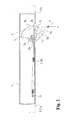
Fig. 1 is a perspective structural view showing a usage state of an assist mechanism according to an embodiment of the present invention structured by applying the invention, and shows an upper portion side of a door viewed from a lower side. -
Fig. 2 is a structural view showing a receiving member viewed from the lower side so that a movement of the receiving member of the assist mechanism ofFig. 1 can be easily understood, and shows a state wherein the receiving member is in a standby position. -
Fig. 3 is a structural view showing the receiving member viewed from the lower side so that the movement of the receiving member of the assist mechanism ofFig. 1 can be easily understood, and shows a state wherein the receiving member is moved up to a wrap-around position by capturing a striker. -
Fig. 4 is a perspective structural view separately showing members on a striker side structuring the assist mechanism, and the upper portion side of the door in which engraving for assembling the members on the striker side is provided. -
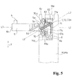
Fig. 5 is a vertical cross-sectional view of the members on the striker side structuring the assist mechanism. -
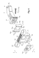
Fig. 6 is an exploded perspective view of the members on the striker side structuring the assist mechanism. -
Fig. 7 is an exploded perspective view showing the members on the striker side structuring the assist mechanism viewed from an opposite direction ofFig. 6 . -
Fig. 8 is a perspective view of a front-side clamping body structuring the members on the striker side structuring the assist mechanism. -
Fig. 9 is a cross-sectional view taken along a line A to A inFig. 8 . -
Fig. 10 is a perspective view of a back-side clamping body structuring the members on the striker side structuring the assist mechanism. -
Fig. 11 is a cross-sectional view taken along a line B to B inFig. 10 . -
Fig. 12 is a front view of the back-side clamping body. -
Fig. 13 is a back view of the back-side clamping body. -
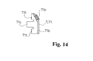
Fig. 14 is a cross-sectional view taken along a line C to C inFig. 12 . - Hereinafter, with reference to
Figs. 1 to 14 , typical embodiments of the present invention will be explained. An assist mechanism of a rotating body M according to the present embodiment functions in such a way as to assist (aid) a forward movement thereof during a period from a predetermined forward-moving position to a forward-moving ending position relative to the rotating body M which is moved forward toward the forward-moving ending position. - Such rotating body M is supported by a supporting body F so as to be rotatable to a forward movement and to a backward movement. Typically, although a door, a hinged door, or the like is used, the rotating body M is not limited to the above provided that the rotating body M is supported by the supporting body F so as to be rotatable to the forward movement and to the backward movement. In an illustrated example, an example in which the assist mechanism is provided in a door Ma and a door frame Fa is shown.
- In the illustrated example, the door Ma as the rotating body M blocks an opening portion Fc which is in an inward portion of the door frame Fa in a closing position (forward-moving ending position) wherein one surface Mb, which becomes the forefront at a time of the forward movement, is bumped into a doorstop portion Fb of the door frame Fa as the supporting body F. Then, if the door Ma as the rotating body M is operated to be moved forward toward the aforementioned closing position from an open position which does not block such opening portion Fc, in a process of the forward movement, a
striker 4 structuring the assist mechanism abuts against a receiving member 1 structuring the assist mechanism, and the door Ma is subjected to the action of the assist mechanism up to such closing position. - In the illustrated example,
such striker 4 is attached to a side of the door Ma as the rotating body M. Therefore, in the illustrated example, the receiving member 1 is provided on a side of the door frame Fa as the supporting body F. Incidentally, aside from the illustrated example, even if thestriker 4 is attached to the side of the door frame Fa as the supporting body F, and the receiving member 1 is provided on a door Ma side as the rotating body M, the forward movement of such rotating body M can be assisted from mid-flow thereof of the forward movement. - In the illustrated example, the
striker 4 is positioned in front of one surface Mb, which becomes the forefront at the time of the forward movement in the door Ma, through a supportingarm 5 and abase 6. More specifically, in the illustrated example,such striker 4 is provided on an upper end side of the door Ma on a door hinge side Mc of the door Ma. Thebase 6 includes an attachment portion (both end portions of the later-mentioned head portion 60) relative to the door Ma as the rotating body M. On the other hand, the supportingarm 5 supports thestriker 4 in anarm end portion 5b thereof. The supportingarm 5 is assembled to thebase 6 so as to be capable of adjusting positions of the top and bottom, and the right and left through the later-mentioned adjusting means 7 in anarm base portion 5a.Such striker 4 is structured as an axis-like body protruding upward from thearm end portion 5b of the supportingarm 5. An upper end of thestriker 4 is positioned in a level slightly lower than an upper end surface Me of the door Ma, and at a time of the forward movement toward the closing position of the door Ma, thestriker 4 is captured by the receiving member 1 provided in a frame upper portion of the door frame Fa just before the door Ma is completely closed. The supportingarm 5 is positioned in a lower side of a level of a lower portion of the later-mentionedmain body 2 which rotatably houses the receiving member 1. - On the other hand, the receiving member 1 is structured so as to move after capturing the
striker 4 at the predetermined forward-moving position of the rotating body M, and to assist the forward movement of the rotating body M to the forward-moving ending position. - In the illustrated example, such receiving member 1 is rotatably combined with the
main body 2 so as to move between a standby position and a wrap-around position. Suchmain body 2 comprises a ceiling portion 2a as an attachment portion to the frame upper portion of the door frame Fa, and the receiving member 1 is rotatably supported in themain body 2 with avertical axis 2b protruding downward from the ceiling portion 2a of themain body 2. Such receiving member 1 comprises an approximately fan-shaped outline in a state viewed from a bottom face, and also comprises an axis hole 1a relative to the aforementionedvertical axis 2b in a main part of the fan shape. Also, in such receiving member 1, acapture recess 1c is formed in such a way as to be open in a fan-shaped border 1b with the aforementioned fan shape, and also to be recessed toward an axis hole 1a side from the fan-shaped border 1b. Then, in the illustrated example, in the aforementioned standby position, anentrance 1d of thecapture recess 1c of the receiving member 1 is faced to an approaching side, i.e., a front side of the door Ma at the time of the forward movement, and also (Fig. 2 ) if the door Ma is moved forward to thecapture recess 1c of the receiving member 1, which is in the standby position, up to the predetermined forward-moving position, thestriker 4 is made so as to be entered. (At the time of the forward movement, aninner wall 1e on a front side among recessinner walls 1e and 1f, which is located on anentrance 1d side of thecapture recess 1c which is in the standby position, is located laterally from a movement locus x of thestriker 4, and the inner wall 1f on a back side is allowed to be positioned on the movement locus x (Fig. 2 ).) Then, if thestriker 4 is entered into thecapture recess 1c in this manner, the receiving member 1 is positively rotated toward the wrap-around position which turns theentrance 1d of thecapture recess 1c toward a backward side, and also the normal rotation is subjected to an urging force of urging means 3 from mid-flow thereof, so that by the receiving member 1 which is positively rotated in this manner, the forward movement toward the forward-moving ending position of the door Ma is assisted. In the illustrated example, such urging means 3 is structured by a helical extension spring 3a provided in themain body 2 in such a way that onespring end 3b is fastened to a fan-shaped border 1b side of the receiving member 1, and theother spring end 3c is fastened to themain body 2, and also that a size between both these spring ends 3b and 3c reaches its maximum size in an intermediate position between the standby position and the wrap-around position of the receiving member 1. Then, such spring 3a allows to assist the forward movement of the aforementioned door Ma, and to maintain states wherein the receiving member 1 is in the standby position and the wrap-around position. Namely, in the illustrated example, such spring 3a is extended the most at the aforementioned intermediate position wherein both the spring ends 3b and 3c and thevertical axis 2b are located on the approximately same virtual straight line. Thereby, if the receiving member 1, which has received thestriker 4 in thecapture recess 1c, is moved along with the forward movement of the door Ma up to a position which exceeds the intermediate position from the standby position, the receiving member 1 is forcedly rotated positively up to the wrap-around position after the intermediate position by urging of the aforementioned spring 3a so as to assist the forward movement of the door Ma. Also, when the receiving member 1 is in the standby position, the positive rotation of the receiving member 1 extends the aforementioned spring 3a, and also when the receiving member 1 is in the wrap-around position, a reverse rotation of the receiving member 1 also extends the aforementioned spring 3a. Accordingly, states wherein the receiving member 1 is in the standby position and in the wrap-around position, are respectively maintained by such spring 3a. If the aforementioned positive rotation of the receiving member 1 is subjected to a braking force by using a damper device and the like which are not shown in the drawings, the forward movement of the assisted door Ma can be carried out slowly. If the door Ma which is in the forward-moving ending position is moved backward, the receiving member 1 which has captured thestriker 4 is rotated reversely along with the aforementioned backward movement up to the standby position, and if the receiving member 1 reaches the standby position, thestriker 4 slips out of thecapture recess 1c, and is released, so that the door Ma is allowed to move backward. - Also, in the assist mechanism according to the present embodiment, the
striker 4 is provided on the door Ma side as the rotating body M in the illustrated example so as to be capable of adjusting the positions of the top and bottom, and the right and left by the supportingarm 5 assembled to thebase 6 through the adjusting means 7. Namely, in the illustrated example, a position of thestriker 4 can be adjusted in a top-and-bottom direction and a right-and-left direction of the door Ma. - If the door Ma as the rotating body M is moved forward up to the predetermined forward-moving position, the
striker 4 is captured by the receiving member 1, and due to the movement of the receiving member 1 after this capture, the forward movement of the door Ma toward the forward-moving ending position is assisted through thestriker 4. However, assisting such forward movement cannot be realized unless thestriker 4 and the receiving member 1 are respectively disposed appropriately. If the aforementioned disposition is inappropriate, even if the door Ma is moved forward, thestriker 4 cannot be appropriately captured by the receiving member 1, so that a desired movement of the assist mechanism cannot be realized. In the present embodiment, due to the aforementioned adjusting means 7, an assembling position of the supportingarm 5 relative to thebase 6, i.e., the position of thestriker 4 can be adjusted to the top, bottom, right, and left with a high degree of freedom without the necessity of reattachment of thebase 6, so that thestriker 4 can be appropriately captured in the receiving member 1. - More specifically, the supporting
arm 5 is bent between thearm base portion 5a and thearm end portion 5b, and thearm end portion 5b is positioned laterally in thearm base portion 5a. In thearm base portion 5a, there is formed aseat plate 5c having a square-shaped disk form. The supportingarm 5 is formed so as to protrude forward from a front surface of theseat plate 5c. On a lower portion side of thearm base portion 5a, there is formed arecess 5d, and also there is formed a throughhole 5e of a bolt 72a, which becomes the later-mentioned fastening means 72, ranging between a central portion of theseat plate 5c and a wall portion positioned on aseat plate 5c side in therecess 5d in a passing-through state. In the throughhole 5e, a hole opening on theaforementioned recess 5d side is positioned more downward than a hole opening on theseat plate 5c side, and the bolt 72a, which is inserted and passed through the throughhole 5e from therecess 5d side, crosses a center line L2 of the bolt 72a in the top-and-bottom direction relative to a virtual horizontal line L1 passing the center of the supportingarm 5. (Fig. 5 ) Such bolt 72a is screwed to ascrew hole 71e as a nut portion formed in the later-mentioned back-side clamping body 71 positioned on a back surface side of thebase 6 from a lower side through the throughhole 5e formed on a lower portion side of the supportingarm 5. A screwing-forward operation of such bolt 72a, i.e., a fastening operation or a screwing-backward operation is allowed to be easily carried out from the lower side. - Also, the
base 6 comprises ahead portion 60 formed long in the right-and-left direction, and amain body portion 61 whose upper portion is integrally connected to thehead portion 60 between both ends of thehead portion 60. Themain body portion 61 comprises an approximately square-shapedfront surface 61a and backsurface 61b, and also comprises a square-shapedwindow hole 62 passing through thefront surface 61a and theback surface 61b in a central portion thereof. - Specifically, the
front surface 61a and theback surface 61b of themain body portion 61 respectively include an upper side, a lower side, and right and left sides. Also, thefront surface 61a and theback surface 61b of themain body portion 61 are respectively surrounded by anupper wall 63, alower wall 64, and right and leftside walls head portion 60, there are respectively formed throughholes 60a for a screw which has been passed through thehead portion 60 in the top-and-bottom direction. In the illustrated example, through the use of an engraving Md formed in the door Ma as the rotating body M, the supportingarm 5 is protruded forward from one surface Mb side of the door Ma, so that thebase 6 is attached to the upper end side of the door Ma. (Fig. 1 andFig. 4 ) Such engraving Md is open respectively on an upper end surface Me of the door Ma and one surface Mb side of the door Ma. In the illustrated example, after thebase 6 is housed in such engraving Md from the upper side by making a lower portion side of themain body portion 61 of thebase 6 foremost, screws S are screwed to the door Ma side through the throughholes 60a so as to attach thebase 6 to the door Ma. Thefront surface 61a of thebase 6 faces an open portion of the engraving Md which is located on one surface Mb side of the door Ma, and the supportingarm 5 is protruded forward from there. - Also, in the present embodiment, the adjusting means 7 comprises a pair of clamping bodies clamping the
base 6 from the front and back; and fastening means 72 fastening the supportingarm 5 and thebase 6 by the fastening operation, and also pressing the pair of clamping bodies against thebase 6 by the fastening operation. - Also, in the illustrated example, one of the pair of clamping bodies is located on a
front surface 61a side of themain body portion 61 of thebase 6, and is supported movably in the right-and-left direction relative to thebase 6. (Hereinafter, one clamping body is called as a front-side clamping body 70.) Also, the other of the pair of clamping bodies is located on aback surface 61b side of themain body portion 61 of thebase 6, and is movably supported in the top-and-bottom direction relative to the front-side clamping body 70. (Hereinafter, the other clamping body is called as the back-side clamping body 71.) - Specifically, the front-
side clamping body 70 is structured by metal, and is structured in such a way as to have an approximately square-shaped plate form. In the front-side clamping body 70, a size in the top-and-bottom direction is approximately equal to an interval between theupper wall 63 on thefront surface 61a side of themain body portion 61 of thebase 6 and thelower wall 64. Also, a size in the right-and-left direction is made smaller than an interval between the right and leftside walls front surface 61a side. Then, in such front-side clamping body 70, the upper side of the front-side clamping body 70 is guided by theupper wall 63, and the lower side of the front-side clamping body 70 is guided by thelower wall 64 so as to be combined with thebase 6 movably in the right-and-left direction. In the center of the front-side clamping body 70, there is formed aguide window hole 70a communicated with thewindow hole 62 of thebase 6. Theguide window hole 70a has a rectangle shape whose top-and-bottom direction is a length side. Also, in the left side and the right side of the front-side clamping body 70, there are respectively formed protrudingportions 70b protruding forward. The protrudingportions 70b are formed by bending a metal plate structuring the front-side clamping body 70. Also, on both right and left sides clamping theguide window hole 70a of the front-side clamping body 70, there are respectively formedspike portions 70c digging into thefront surface 61a of themain body portion 61 structuring thebase 6 by the fastening operation of the fastening means 72. In the illustrated example, on both right and left sides clamping theguide window hole 70a, thespike portions 70c in four portions are respectively arranged up and down leaving an interval between theadjacent spike portions 70c. When a throughhole 70d is formed in the front-side clamping body 70 from a front surface side thereof, eachspike portion 70c respectively comprises a circling projectingportion 70e circling a hole border of the throughhole 70d formed on a back surface side thereof. (Fig. 9 ) - On the other hand, the back-
side clamping body 71 is also structured by metal. The back-side clamping body 71 comprises an approximatelyquadrangular frame portion 71a comprising an upper side, a lower side, and right and left sides; across-link portion 71b ranged between the center of an upper portion and the center of a lower portion of theframe portion 71a; and a right-and-left pair ofarm portions cross-link portion 71b. In theframe portion 71a of the back-side clamping body 71, a size in the top-and-bottom direction is made smaller than an interval between theupper wall 63 and thelower wall 64 on theback surface 61b side of themain body portion 61 of thebase 6. Also, a size in the right-and-left direction is made smaller than an interval between the right and leftside walls back surface 61b side. Also, the pair ofarm portions frame portion 71a, and is structured in such a way as to have a plate shape whose plate surface follows the top-and-bottom direction. A size in the top-and-bottom direction of the pair ofarm portions guide window hole 70a of the front-side clamping body 70, and an interval between outside surfaces of the pair ofarm portions guide window hole 70a of the front-side clamping body 70. Then, in such back-side clamping body 71, in a state wherein theframe portion 71a is additionally placed in theback surface 61b of thebase 6, the arm end of the pair ofarm portions guide window hole 70a of the front-side clamping body 70 through thewindow hole 62 of thebase 6, and the back-side clamping body 71 is guided by theguide window hole 70a so as to be combined with the front-side clamping body 70 movably in the top-and-bottom direction. In the illustrated example, connecting portions between thecross-link portion 71b of the back-side clamping body 71 and thecross-link portion 71b in theframe portion 71a are structured by bending the metal plate forward so as to form arecess 71d, and the connecting portions protrude more backwardly than theback surface 61b of theframe portion 71a. In connecting portions between thecross-link portion 71b in an upper side in theframe portion 71a, there is formed thescrew hole 71e as the nut portion receiving the bolt 72a which becomes the fastening means 72 from an oblique lower side. Also, respectively on the upper side and the lower side of theframe portion 71a of the back-side clamping body 71, and respectively on both right and left sides clamping thecross-link portion 71b, there are formedspike portions 71f digging into theback surface 61b of themain body portion 61 structuring thebase 6 by the fastening operation of the fastening means 72. In the illustrated example, on both right and left sides clamping thecross-link portion 71b, thespike portions 71f in two portions are respectively arranged right and left leaving an interval between theadjacent spike portions 71f. When a through hole 71g is formed in theframe portion 71a of the back-side clamping body 71 from a front surface side thereof, eachspike portion 71f respectively comprises a circling projectingportion 71h circling a hole border of the through hole 71g formed on a back surface side thereof. (Fig. 11 ) - An interval between the right and left protruding
portions 70b of the front-side clamping body 70 is approximately equal to a right-and-left size of theseat plate 5c of the supportingarm 5, and in a state wherein theseat plate 5c is attached to thefront surface 61a of the front-side clamping body 70, the supportingarm 5 is housed between the right-and-left protrudingportions 70b of the front-side clamping body 70. Also, a top-to-bottom size of theseat plate 5c of the supportingarm 5 is smaller than the interval between theupper wall 63 and thelower wall 64 on thefront surface 61a of themain body portion 61 of thebase 6. The bolt 72a as the fastening means 72 passes through theguide window hole 70a of the front-side clamping body 70 and thewindow hole 62 of thebase 6 through the throughhole 5e of the supportingarm 5 so as to be capable of being screwed to thescrew hole 71e of the back-side clamping body 71. When the bolt 72a is screwed forward, i.e., is fastened, theseat plate 5c of the supportingarm 5 is pressed against the front surface of the front-side clamping body 70, and also themain body portion 61 of thebase 6 is clamped between the back surface of the front-side clamping body 70 and the front surface of theframe portion 71a of the back-side clamping body 71. Thereby, the supportingarm 5 is fixed to thebase 6, and thestriker 4 is positioned in a predetermined position. - The pair of clamping bodies, i.e., the front-
side clamping body 70 and the back-side clamping body 71 respectively comprise thespike portions base 6 by the fastening operation of the fastening means 72, so that a fixation state of the supportingarm 5 relative to thebase 6 is stably maintained, and thestriker 4 can be stably positioned in the predetermined position. Typically, thebase 6 is made of synthetic resin, and the pair of clamping bodies is structured by a material with a higher degree of hardness than that of thebase 6. - In
such spike portions holes 70d and 71g are formed in the metallic clamping bodies in the aforementioned manner from one surface side thereof typically by punching processing, in a case where the throughholes 70d and 71g comprise the circling projectingportions portions spike portions base 6. - Also, in the present embodiment, the bolt 72a structuring the fastening means 72 is disposed in such a way as to cross the center line L2 of the bolt 72a in the top-and-bottom direction relative to the virtual horizontal line L1 passing the center of the supporting
arm 5, so that with the single bolt 72a, the supportingarm 5 can be stably fixed relative to thebase 6 in the aforementioned manner. - Also, as mentioned above, one of the pair of clamping bodies, in the illustrated example, the front-
side clamping body 70 is supported in thebase 6 movably in the right-and-left direction, and the other of the pair of clamping bodies, in the illustrated example, the back-side clamping body 71 is supported in the front-side clamping body 70 movably in the top-and-bottom direction. Accordingly, by loosening the bolt 72a structuring the fastening means, the position of the supportingarm 5, i.e., the position of thestriker 4 can be moved and adjusted to the top, bottom, right, and left, and after the adjustment, the bolt 72a is fastened, so that the supportingarm 5 is fixed to thebase 6, and thestriker 4 can be positioned to be appropriately captured in the receiving member in the predetermined forward-moving position of the rotating body M. - All contents of the specification, claims, drawings, and abstract of Japanese Patent Application No.
2009-250131 filed on October 30, 2009
Claims (8)
- An assist mechanism for a rotating body, comprising:a striker adapted to be provided on one of either a rotating body or a supporting body rotatably supporting the rotating body; anda receiving member adapted to be provided on the other of the rotating body or the supporting body, the receiving member moving after capturing the striker at a predetermined forward-moving position of the rotating body, and assisting a forward movement of the rotating body to a forward-moving ending position,wherein the striker is supported in a supporting arm, and is structured by assembling the supporting arm in a base attached to one of either the rotating body or the supporting body to be capable of adjusting positions for the top and bottom, and the right and left through an adjusting device.
- An assist mechanism for a rotating body according to claim 1, wherein the adjusting device comprises a pair of clamping bodies clamping the base from front and back; and a fastening device fastening the supporting arm and the base by a fastening operation, and pressing the pair of clamping bodies against the base by the fastening operation.
- An assist mechanism for a rotating body according to claim 2, wherein one of the pair of clamping bodies is supported movably in a top-and-bottom direction or a right-and-left direction relative to the base, and
when the one clamping body is supported in the base movably in the top-and-bottom direction, the other of the pair of clamping bodies is supported movably in the right-and-left direction relative to the one clamping body, and when the one clamping body is supported in the base movably in the right-and-left direction, the other of the pair of clamping bodies is supported movably in the top-and-bottom direction. - An assist mechanism for a rotating body according to claim 2 or 3, wherein the pair of clamping bodies respectively comprises spike portions digging into the base due to the fastening operation of the fastening device.
- An assist mechanism for a rotating body according to claim 4, wherein when a through hole is formed in a metallic clamping body from one surface side thereof, a circular projecting portion circling a hole border of the through hole is formed on the other surface side thereof, and the circular projecting portion is made as the spike portion.
- An assist mechanism for a rotating body according to claim 2, wherein the fastening device is a bolt screwed to a nut portion formed in the clamping body positioned on a back surface side of the base.
- An assist mechanism for a rotating body according to claim 6, wherein the bolt is disposed to cross a center line of the bolt in the top-and-bottom direction relative to a virtual horizontal line passing a center of the supporting arm.
- An assist mechanism for a rotating body according to claim 7, wherein the bolt is screwed to the nut portion formed in the clamping body positioned on the back surface side of the base from a lower side through a through hole formed on a lower portion side of the supporting arm.
Applications Claiming Priority (2)
| Application Number | Priority Date | Filing Date | Title |
|---|---|---|---|
| JP2009250131A JP5377227B2 (en) | 2009-10-30 | 2009-10-30 | Rotating body assist mechanism |
| PCT/JP2010/068092 WO2011052394A1 (en) | 2009-10-30 | 2010-10-14 | Assist mechanism for rotating body |
Publications (1)
| Publication Number | Publication Date |
|---|---|
| EP2495384A1 true EP2495384A1 (en) | 2012-09-05 |
Family
ID=43921820
Family Applications (1)
| Application Number | Title | Priority Date | Filing Date |
|---|---|---|---|
| EP10826528A Withdrawn EP2495384A1 (en) | 2009-10-30 | 2010-10-14 | Assist mechanism for rotating body |
Country Status (5)
| Country | Link |
|---|---|
| EP (1) | EP2495384A1 (en) |
| JP (1) | JP5377227B2 (en) |
| KR (1) | KR20120036370A (en) |
| CN (1) | CN102597403A (en) |
| WO (1) | WO2011052394A1 (en) |
Cited By (1)
| Publication number | Priority date | Publication date | Assignee | Title |
|---|---|---|---|---|
| EP2397632A4 (en) * | 2009-02-12 | 2014-06-04 | Nifco Inc | MECHANISM FOR AIDING A BODY |
Family Cites Families (9)
| Publication number | Priority date | Publication date | Assignee | Title |
|---|---|---|---|---|
| JPS58186070U (en) * | 1982-06-04 | 1983-12-10 | 吉村 富雄 | Mounting structure of the pedestal part of the hanging bracket |
| JPS58195754U (en) * | 1982-06-22 | 1983-12-26 | ワイケイケイ株式会社 | Lock holder mounting structure |
| JPH01126181U (en) * | 1988-02-24 | 1989-08-29 | ||
| JP3051640U (en) * | 1998-02-20 | 1998-09-02 | エスエム工業株式会社 | Mounting structure of curtain opening / closing device |
| JP4772566B2 (en) * | 2005-04-27 | 2011-09-14 | 株式会社Lixil | Mounting structure for handrail support |
| JP4796816B2 (en) | 2005-10-28 | 2011-10-19 | 株式会社ムラコシ精工 | Door body closing device |
| JP4661592B2 (en) * | 2005-12-27 | 2011-03-30 | 中西金属工業株式会社 | Door closer |
| JP2009250131A (en) | 2008-04-07 | 2009-10-29 | Mitsuba Corp | Cooling system |
| JP5210927B2 (en) * | 2009-03-09 | 2013-06-12 | 株式会社ムラコシ精工 | Locking pin support device for door closing device |
-
2009
- 2009-10-30 JP JP2009250131A patent/JP5377227B2/en not_active Expired - Fee Related
-
2010
- 2010-10-14 EP EP10826528A patent/EP2495384A1/en not_active Withdrawn
- 2010-10-14 CN CN2010800493066A patent/CN102597403A/en active Pending
- 2010-10-14 WO PCT/JP2010/068092 patent/WO2011052394A1/en not_active Ceased
- 2010-10-14 KR KR1020127004380A patent/KR20120036370A/en not_active Ceased
Non-Patent Citations (1)
| Title |
|---|
| See references of WO2011052394A1 * |
Cited By (1)
| Publication number | Priority date | Publication date | Assignee | Title |
|---|---|---|---|---|
| EP2397632A4 (en) * | 2009-02-12 | 2014-06-04 | Nifco Inc | MECHANISM FOR AIDING A BODY |
Also Published As
| Publication number | Publication date |
|---|---|
| WO2011052394A1 (en) | 2011-05-05 |
| JP2011094401A (en) | 2011-05-12 |
| JP5377227B2 (en) | 2013-12-25 |
| KR20120036370A (en) | 2012-04-17 |
| CN102597403A (en) | 2012-07-18 |
Similar Documents
| Publication | Publication Date | Title |
|---|---|---|
| US6981752B2 (en) | Front panel mounting device for a drawer | |
| US11168502B2 (en) | Door device | |
| ES3057933T3 (en) | Fitting device | |
| JP5295774B2 (en) | Device for opening and holding a revolving door | |
| EP2060719A2 (en) | Damping device group for furniture hinges | |
| US6286262B1 (en) | Fitting having support arm or swing arm for supporting a turning sash or a turning-tilting sash | |
| CN110306896B (en) | Door body moving device | |
| RU2684453C1 (en) | Fitting system for attaching of a movable and folded back sash | |
| US8596693B2 (en) | Locking unit | |
| KR101254436B1 (en) | Assist mechanism for pivoting body | |
| KR101043377B1 (en) | Swivel Stay Bar | |
| EP2495384A1 (en) | Assist mechanism for rotating body | |
| CN108851656A (en) | Sliding rail assembly | |
| JP6666618B2 (en) | Sliding window opening setting device | |
| US20030029091A1 (en) | Pivot-tilt mechanism for a door or window | |
| JP2003301651A (en) | Door stop device | |
| JP4380090B2 (en) | Door positioning device | |
| JP3546327B2 (en) | Door opening / closing device | |
| KR102537390B1 (en) | Automatic close device for fire door | |
| KR100972685B1 (en) | Door hinge | |
| KR101288872B1 (en) | Opening nad shutting device for furniture | |
| CN213869327U (en) | Lock box structure for inward opening and inward reversing door and window | |
| CN106661907B (en) | Slide carriage device with eccentricity control pin and the sliding door with such slide carriage device or sliding window | |
| KR102375245B1 (en) | Door latch for easy opening and closing doors | |
| TW202417727A (en) | Foldable-door hinge and functional entity with a foldable door |
Legal Events
| Date | Code | Title | Description |
|---|---|---|---|
| PUAI | Public reference made under article 153(3) epc to a published international application that has entered the european phase |
Free format text: ORIGINAL CODE: 0009012 |
|
| 17P | Request for examination filed |
Effective date: 20120419 |
|
| AK | Designated contracting states |
Kind code of ref document: A1 Designated state(s): AL AT BE BG CH CY CZ DE DK EE ES FI FR GB GR HR HU IE IS IT LI LT LU LV MC MK MT NL NO PL PT RO RS SE SI SK SM TR |
|
| DAX | Request for extension of the european patent (deleted) | ||
| STAA | Information on the status of an ep patent application or granted ep patent |
Free format text: STATUS: THE APPLICATION IS DEEMED TO BE WITHDRAWN |
|
| 18D | Application deemed to be withdrawn |
Effective date: 20160503 |