EP2495120B1 - Opening seal for automobiles and method of preparing the same - Google Patents
Opening seal for automobiles and method of preparing the same Download PDFInfo
- Publication number
- EP2495120B1 EP2495120B1 EP12156642.6A EP12156642A EP2495120B1 EP 2495120 B1 EP2495120 B1 EP 2495120B1 EP 12156642 A EP12156642 A EP 12156642A EP 2495120 B1 EP2495120 B1 EP 2495120B1
- Authority
- EP
- European Patent Office
- Prior art keywords
- cabin side
- thermo
- cabin
- wire body
- base member
- Prior art date
- Legal status (The legal status is an assumption and is not a legal conclusion. Google has not performed a legal analysis and makes no representation as to the accuracy of the status listed.)
- Active
Links
Images



Classifications
-
- B—PERFORMING OPERATIONS; TRANSPORTING
- B60—VEHICLES IN GENERAL
- B60J—WINDOWS, WINDSCREENS, NON-FIXED ROOFS, DOORS, OR SIMILAR DEVICES FOR VEHICLES; REMOVABLE EXTERNAL PROTECTIVE COVERINGS SPECIALLY ADAPTED FOR VEHICLES
- B60J10/00—Sealing arrangements
-
- B—PERFORMING OPERATIONS; TRANSPORTING
- B60—VEHICLES IN GENERAL
- B60J—WINDOWS, WINDSCREENS, NON-FIXED ROOFS, DOORS, OR SIMILAR DEVICES FOR VEHICLES; REMOVABLE EXTERNAL PROTECTIVE COVERINGS SPECIALLY ADAPTED FOR VEHICLES
- B60J10/00—Sealing arrangements
- B60J10/15—Sealing arrangements characterised by the material
- B60J10/18—Sealing arrangements characterised by the material provided with reinforcements or inserts
-
- B—PERFORMING OPERATIONS; TRANSPORTING
- B60—VEHICLES IN GENERAL
- B60J—WINDOWS, WINDSCREENS, NON-FIXED ROOFS, DOORS, OR SIMILAR DEVICES FOR VEHICLES; REMOVABLE EXTERNAL PROTECTIVE COVERINGS SPECIALLY ADAPTED FOR VEHICLES
- B60J10/00—Sealing arrangements
- B60J10/20—Sealing arrangements characterised by the shape
- B60J10/24—Sealing arrangements characterised by the shape having tubular parts
-
- B—PERFORMING OPERATIONS; TRANSPORTING
- B60—VEHICLES IN GENERAL
- B60J—WINDOWS, WINDSCREENS, NON-FIXED ROOFS, DOORS, OR SIMILAR DEVICES FOR VEHICLES; REMOVABLE EXTERNAL PROTECTIVE COVERINGS SPECIALLY ADAPTED FOR VEHICLES
- B60J10/00—Sealing arrangements
- B60J10/30—Sealing arrangements characterised by the fastening means
- B60J10/32—Sealing arrangements characterised by the fastening means using integral U-shaped retainers
-
- B—PERFORMING OPERATIONS; TRANSPORTING
- B60—VEHICLES IN GENERAL
- B60J—WINDOWS, WINDSCREENS, NON-FIXED ROOFS, DOORS, OR SIMILAR DEVICES FOR VEHICLES; REMOVABLE EXTERNAL PROTECTIVE COVERINGS SPECIALLY ADAPTED FOR VEHICLES
- B60J10/00—Sealing arrangements
- B60J10/80—Sealing arrangements specially adapted for opening panels, e.g. doors
- B60J10/84—Sealing arrangements specially adapted for opening panels, e.g. doors arranged on the vehicle body
-
- B—PERFORMING OPERATIONS; TRANSPORTING
- B60—VEHICLES IN GENERAL
- B60R—VEHICLES, VEHICLE FITTINGS, OR VEHICLE PARTS, NOT OTHERWISE PROVIDED FOR
- B60R13/00—Elements for body-finishing, identifying, or decorating; Arrangements or adaptations for advertising purposes
- B60R13/06—Sealing strips
-
- Y—GENERAL TAGGING OF NEW TECHNOLOGICAL DEVELOPMENTS; GENERAL TAGGING OF CROSS-SECTIONAL TECHNOLOGIES SPANNING OVER SEVERAL SECTIONS OF THE IPC; TECHNICAL SUBJECTS COVERED BY FORMER USPC CROSS-REFERENCE ART COLLECTIONS [XRACs] AND DIGESTS
- Y10—TECHNICAL SUBJECTS COVERED BY FORMER USPC
- Y10S—TECHNICAL SUBJECTS COVERED BY FORMER USPC CROSS-REFERENCE ART COLLECTIONS [XRACs] AND DIGESTS
- Y10S277/00—Seal for a joint or juncture
- Y10S277/921—Closure or weather strip seal
Definitions
- the present invention relates to opening seals for automobiles and method of preparing the same having wire core embedded in installation base members thereof for increasing rigidity, which are installed along peripheries of door opening parts of automobile bodies for sealing openings between bodies and doors by making elastic contact with the doors when the doors are closed.
- an opening seal 10 for automobiles having a wire core 20 embedded therein has been well-known, which is mounted on a flange 3 installed along a periphery of a door 2 opening part on an automobile body 1 side for making elastic contact with the door 2 when the door 2 is closed to seal an opening between the body 1 and the door 2 (see, for example, the Japanese unexamined Patent Publication Nos. H03-82519 and 2004-322768 ).
- Fig. 8 is a side view of an automobile having the opening seal 10 for automobiles mounted thereon; and Fig. 9 is an enlarged perspective view of an important part of 100 of Fig. 8 , showing the opening seal 10 for automobiles.
- the opening seal 10 for automobiles comprises a cross section roughly U-shaped installation base member 11 including an outer-cabin side wall 11a, an inner-cabin side wall 11b and a connecting wall 11c which connects the side walls 11a and 11b; a hollow seal member 12 provided on an outer-cabin side of the installation base member 11; and a protuberance 13 provided inside the inner-cabin side wall 11b of the installation base member 11, which makes elastic contact with and holds the flange 3.
- the outer-cabin side wall 11a has a plurality of projections 14 provided inside, which make elastic contact with the flange 3; and the installation base member 11 has a lip 15 provided on an inner-cabin side thereof.
- Decorative coating material 16 is provided from the lip 15 to a surface of the connecting wall 11c of the installation base member 11 for decorating appearance from an inner-cabin side.
- the wire core 20 embedded in the installation base member 11 of the opening seal 10 for automobiles comprises : a skeletal wire body 21 formed by consecutively bending a wire; and yarns 22, 23 partially connected with the wire body 21 for preventing expansion of the wire body 21 in a longitudinal direction.
- the wire core 20 is finally embedded in a longitudinal direction of the installation base member 11 while the wire core 20, consecutively bent into U shapes in the same direction at regular intervals in advance, is bent into a rough U-shape.
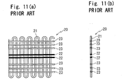
- Examples of use of the yarns for preventing expansion of the wire body 21 in a longitudinal direction include: a plurality of non-thermo-fusible yarns 22 which do not melt at set vulcanization temperature for vulcanizing rubber component when preparing the opening seal 10 for automobiles as shown in Fig. 9 and Fig. 10 (six non-thermo-fusible yarns in Fig. 9 and Fig. 10 ); and a combination of the non-thermo-fusible yarns 22 which do not melt at the set vulcanization temperature and thermo-fusible yarns 23 which do not melt at the time of an extrusion molding and melt at the set vulcanization temperature as shown in Fig. 11 (two non-thermo -fusible yarns 22 and six thermo-fusible yarns 23 in Fig. 11 ).
- Such a structure controls unnecessary expansion of the opening seal 10 for automobiles at the time of the extrusion molding and the preparation of the opening seal 10 for automobiles and improves rigidity of the installation base member 11 after molding, thereby improving assembly force of the opening seal 10 for automobiles on the flange 3.
- the straight line 200 connects the non-thermo-fusible yarn 22 (22a) embedded on a greater opening edge side on the outer-cabin side wall 11a of the installation base member 11 with the non-thermo-fusible yarn 22 (22b) embedded on a greater opening edge side on the inner-cabin side wall 11b of the installation base member 11.
- the expansion and contraction of the hollow seal member 12 hamper stabilization of the assembled state of the opening seal 10 for automobiles, which degrades external appearance and sealing function. Such problems are remarkable when the folding wrinkles 202 generate.
- the Japanese unexamined Patent Publication No. H03-82519 discloses to connect each of three sides of the wire core 20, respectively embedded in the outer-cabin side wall 11a, an inner-cabin side wall 11b and a connecting wall 11c of the installation base member 11, with the yarns which are thermally degraded at the set vulcanization temperature and the yarns which are not thermally degraded (non-thermo-fusible yarn) at the set vulcanization temperature.
- the resultant opening seal is excellent in strength toward pulling force at the time of extrusion molding.
- a way of disposing the yarns on each of the three sides of the wire core 20 is rough, only one side of the wire core 20 with the non-thermo-fusible yarn for example.
- Such a structure does not decrease expanding or contracting state on the hollow seal member 12 sufficiently, especially while the opening seal 10 for automobiles is assembled on the corner part.
- the Japanese unexamined Patent Publication No. 2004-322768 discloses to provide high melting point yarn (non-thermo-fusible yarn) on a part of the inner-cabin side wall 11b, that is at least close to the connecting wall 11c.
- the invention relates to weather strips installed on automobile bodies with curves which are swelled toward width direction of the automobiles. Accordingly, the invention does not decrease expanding or contracting state on the hollow seal member 12 sufficiently while the opening seal 10 for automobiles is assembled on the corner part.
- an object of the present invention is to provide the opening seal for automobiles and method of preparing the same capable of remarkably decreasing the expanding or contracting state on the hollow seal member while the opening seal for automobiles is assembled on the corner part.
- a first aspect of the invention provides an opening seal for automobiles, comprising: an installation base member (11) with a roughly U-shaped cross section mountable on a flange (3) installed along a periphery of a door (2) opening which is part of a vehicle body (1), the base member including an outer-cabin side wall (11a), an inner-cabin side wall (11b) and a connecting wall (11c) connecting the side walls (11a, 11b); a hollow seal member (12) extending from an inner side position (301) and an outer side position (800) of said outer-cabin side wall (11a) of the installation base member (11) respectively toward an internal circumference side (305) and an outer circumference side (304) of a door, which is swelled and curved toward an outer-cabin side (304) for making elastic contact with said door (2) thereby sealing an inside and an outside of the automobile; one or a plurality of protuberances (13) installed inside the inner-cabin side wall (11b)
- a second aspect of the invention provides the opening seal for automobiles according to the first aspect of the invention, wherein: said non-thermo-fusible yarn (221) on the outer-cabin side (306) is provided in a range (402) from a bending end position (21d) forming a shoulder (21a) on the outer-ca.bin side of the wire body (21) which is bent roughly in U-shape to a position (52) determined by offsetting a point (51), on the door internal circumference side (305) of an inner-side base (12a) of said hollow seal member (12), with respect to the wire body (21).
- a third aspect of the invention provides the opening seal for automobiles according to the first or second aspect of the invention, wherein: said non-thermo-fusible yarn (222) on the inner-cabin side (307) is provided in a range (502) from a position (55) on the inner-cabin side determined by offsetting a provided point of said non-thermo-fusible yarn (221) on the outer-cabin side (306) with respect to the wire body (21) to a position (54) determined by offsetting a point (53), on an opening edge side on said inner-cabin side wall (11b) of a base of the protuberance (13) that is positioned on the greater opening edge part side on the inner-cabin side wall (11b) of said installation base member (11) among said one or a plurality of protuberances, with respect to the wire body (21).
- a fourth aspect of the invention provides the opening seal for automobiles according to the second aspect of the invention, wherein: said non-thermo-fusible yarn (222) on the inner-cabin side is provided in a range (503) from a position (57), where a straight line (100) connecting a point (56) on the door internal circumference side (305) on an internal side of the wall of said hollow seal member (12) and a provided point of said non-thermo-fusible yarn (221) on the outer-cabin side intersects the inner-cabin side of the wire body (21), to the position (54) determined by offsetting the point (53), on the opening edge side on said inner-cabin side wall (11b) of the base of the protuberance (13) that is positioned on the greater opening edge part side on the inner-cabin side wall (11b) of said installation base member (11) among said one or a plurality of protuberances, with respect to the wire body (21).
- a fifth aspect of the invention provides the opening seal for automobiles according to the second aspect of the invention, wherein: said non-thermo-fusible yarn (222) on the inner-cabin side is provided in a range (504) from a position (59), where a straight line (300) connecting a point (58) on the door internal circumference side (305) of an outer side of the wall of said hollow seal member (12) and a provided point of said non-thermo-fusible yarn (221) on the outer-cabin side intersects the inner-cabin side of the wire body (21), to the position (54) determined by offsetting the point (53), on the opening edge side on said inner-cabin side wall (11b) of the base of the protuberance (13) that is positioned on the greater opening edge part side on the inner-cabin side wall (11b) of said installation base member (11) among said one or a plurality of protuberances, with respect to the wire body (21).
- An sixth aspect of the invention provides the opening seal for automobiles according to any one of the first to fifth aspects of the invention, wherein: the shoulder (21a) on the outer-cabin side of said installation base member (11) is provided with coating material (31) having higher specific gravity compared with material forming said installation base member (11).
- the installation base member mounted on the flange installed along the periphery of the door opening part of the body has the wire core embedded therein, including the skeletal wire body connected with the non-thermo-fusible yarn which does not melt at set vulcanization temperature. Accordingly, in a course of vulcanization and extrusion molding the opening seal for automobiles, the non-thermo-fusible yarn remains, not melts.
- Such a structure controls unnecessary expansion of the opening seal for automobiles together with the wire core for the effect of the non-thermo-fusible yarns even in case the wire core is pulled with strong force while extrusion molding the opening seal for automobiles in the course of preparation. Also, the structure improves assembly force of the opening seal for automobiles on the flange by improving the rigidity of the installation base member after molding.
- the wire core has at least two non-thermo-fusible yarns respectively provided on the outer-cabin side and the inner-cabin side thereof;
- the non-thermo-fusible yarn on the outer-cabin side is provided in the range from the bending start position forming the shoulder on the outer-cabin side of the wire body which is bent roughly in U-shape to the position determined by offsetting the point, on the door internal circumference side of an inner-side base of the hollow seal member, with respect to the wire body;
- the non-tbermo-fusible yarn on the inner-cabin side is provided in the range from the bending start position forming the shoulder on the inner-cabin side of the wire body which is bent roughly in U-shape to the position determined by offsetting the point, on the opening edge side on said inner-cabin side wall of a base of the protuberance which is positioned on the greater opening edge part side on the inner-cabin side wall of the installation base member, with respect to the wire body.
- the straight line which connects the position of the non-thermo-fusible yarn on the outer-cabin side and the position of the non-thermo-fusible yarn on the inner-cabin side leans toward the internal circumference side from the outer circumference side of a door (toward the connecting wall side from an opening part side of the installation base member) when the door is closed as faced toward the outer-cabin side from the inner-cabin side for the effect of the non-thermo-fusible yarn on the outer-cabin side thus provided.
- the leaned straight line as extended intersects the hollow seal member on a position on the internal circumference side of a door (on the connecting wall side from the opening part side of the installation base member) compared with the prior art ( Fig. 9 ) in which the leaned straight line as extended intersects hollow seal member on a position on the outer circumference side. Accordingly, contracting force functions within a smaller domain of the hollow seal member when the opening seal for automobiles is assembled on a corner part on the body side of the automobile, thereby preventing generation of folding wrinkles.
- Such a structure enables stable assembly of the opening seal for automobiles on the corner part on the body side of the automobile and keeps the opening seal stably assembled after the assembly.
- the non-thermo-fusible yarn on the outer-cabin side is provided from the bending end position, not bending start position forming the shoulder on the outer-cabin side of the wire body which is bent roughly in U-shape. Accordingly, the non-thermo-fusible yarn on the outer-cabin side is provided on the outer-cabin side wall side of the installation base member, changed from the connecting wall side.
- Such a structure improves balance when connecting the wire body and effectively controls unnecessary expansion of the opening seal for automobiles together with the wire core while the opening seal for automobiles together with the non-thermo-fusible yarn on the inner-cabin side is extrusion molded.
- the non-thermo-fusible yarn on the inner-cabin side is provided in a further limited range: from the position on the inner-cabin side, determined by offsetting the providing point of the non-thermo-fusible yarn on the outer-cabin side with respect to the wire body; from the position where the straight line connecting the end on the door internal circumference side on the hollow side of the hollow seal member and the providing point of the non-thermo-fusible yarn on the outer-cabin side intersects the inner-cabin side of the wire body; or from the position where the straight line connecting the end on the door internal circumference side of the hollow seal member and the providing point of the non-thermo-fusible yarn on the outer-cabin side intersects the inner-cabin side of the wire body.
- the leaned straight line as extended intersects the hollow seal member on a position on the internal circumference side of the door, changed from the outer circumference side, that is on the connecting wall side changed from the opening part side of the installation base member. Accordingly, the contracting force functions within a further smaller domain of the hollow seal member when the opening seal for automobiles is assembled on the corner part on the body side, thereby preventing generation of folding wrinkles.
- the fastening force of the installation base member on the flange from the inner-cabin side wall side is increased, which enables the protuberance provided on the inner-cabin side wall side to hold the flange sufficiently.
- the position on the opening edge side of the inner-cabin side wall of each range is determined by offsetting the point, on the opening edge side on the inner-cabin side wall of the base of the protuberance that is positioned on the greater opening edge part side on the inner-cabin side wall of the installation base member among the one or plurality of protuberance, with respect to the wire body.
- the opening seal for automobiles in itself may lean when assembled on the corner part on the automobile body side, which is not a desired assembled state and not favorable.
- the non-thermo-fusible yarn on the inner-cabin side is provided in the range from the position where the straight line connecting the end on the door internal circumference side of the hollow seal member and the providing point of the non-thermo-fusible yarn on the outer-cabin side intersects the inner-cabin side of the wire body to the position determined by offsetting the point on the opening edge side on the inner-cabin side wall of the base of the protuberance that is positioned on the greater opening edge part side on the inner-cabin side wall of the installation base member among the one or plurality of protuberance with respect to the wire body, the straight line which connects the position of the non-thermo-fusible yarn on the outer-cabin side and the position of the non-thermo-fusible yarn on the inner-cabin side, as extended, intersects the hollow seal member on the position which is the end on the door internal circumference side of the hollow seal member or further door internal circumference side. Accordingly, the contracting force does not function on the hollow seal member when the opening seal for
- the contracting force functions only on thickness of the hollow seal member when the opening seal for automobiles is assembled on the corner part on the body side of the automobile so that the folding wrinkles hardly generates.
- the non-thermo-fusible yarn on the inner-cabin side is shifted from the position where the straight line connecting the end on the door internal circumference side on the hollow side of the hollow seal member and the providing point of the non-thermo-fusible yarn on the outer-cabin side intersects the inner-cabin side of the wire body to a position determined by offsetting the point on the opening edge side on the inner-cabin side wall of the base of the protuberance that is positioned on the greater opening edge part side on the inner-cabin side wall of the installation base member among the one or the plurality of protuberance with respect to the wire body, the straight line which connects the position of the non-thermo-fusible yarn on the outer-cabin side and the position of the non-thermo-fusible yarn on the inner-cabin side, as extended, intersects
- the wire body is partially connected with thermo-fusible yarn as well as the non-thermo-fusible yarn, which melts at set vulcanization temperature and roughly linearly extends in the longitudinal direction. Accordingly, the wire body is resistant to the pulling force before vulcanization.
- thermo-fusible yarn is provided on the connecting wall of the installation base member, on the outer-cabin side wall of the installation base member that is the opening edge side of the outer-cabin side wall compared with the providing point of the non-thermo-fusible yarn on the outer-cabin side and on the inner-cabin side wall of the installation base member that is the opening edge side of the inner-cabin side wall compared with the providing point of the non-thermo-fusible yarn on the inner-cabin side. Accordingly, the opening seal for automobiles is well-balanced and the thermo-fusible yarn that vanishes for the vulcanization does not cause expansion and contraction of the hollow seal member when the opening seal for automobiles is assembled on the corner part on the automobile body side.
- the shoulder on the outer-cabin side of the installation base member is provided with coating material having higher specific gravity compared with material forming the installation base member. Accordingly, the opening seal for automobiles is stably assembled on the corner part on the automobile body side and wrinkles do not generate on a part provided with the coating material.
- the non-thermo-fusible yarn on the inner-cabin side may be changed to the thermo-fusible yarn depending on strength of the material on the part.
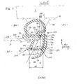
- FIG. 1 is a cross section showing an opening seal 10 for automobiles according to an embodiment of the present invention
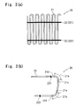
- Fig. 2 shows a cross section of a wire core 20 shown in Fig. 1 .
- the opening seal 10 for automobiles mainly comprises: an installation base member 11; a hollow seal member 12; a protuberance 13; and a wire core 20.
- the installation base member 11 is cross section roughly U-shaped, including an outer-cabin side wall 11a, an inner-cabin side wall 11b and a connecting wall 11c connecting the side walls 11a, 11b.
- the installation base member 11 is installed on a flange 3 installed along a periphery of a door 2 opening part of a body 1 in such a manner that the flange 3 is inserted into the installation base member 11 from an opening part side.
- the flange 3 extends inward along the periphery of the door 2 opening part.
- Bases 12a, 12b of the hollow seal member 12 extend from an inner side position and an outer side position of the outer-cabin side wall 11a of the installation base member 11 respectively toward an internal circumference side and an outer circumference side of a door, which is swelled and curved toward an outer-cabin side.
- the hollow seal member 12 makes elastic contact with the door 2 and seals an inside and an outside of the automobile when the door 2 is closed.
- the protuberance 13 extends from an inside (outer-cabin side) of the inner-cabin side wall 11b of the installation base member 11 toward the connecting wall 11e side.
- the installation base member 11 has a lip 15 provided on an inner-cabin side thereof.
- Decorative coating material 16 is provided from the lip 15 to a surface of the connecting wall 11c of the installation base member 11 for decorating appearance from an inner-cabin side.
- a wire core 20 comprises: a skeletal wire body 21 formed by consecutively bending a wire; and yarn 22 partially connected with the wire body 21 for preventing expansion of the wire body 21 in a longitudinal direction.
- the wire core 20 is finally embedded in a longitudinal direction of the installation base member 11 while the wire core 20, consecutively bent in U shapes in the same direction at regular intervals in advance, is bent into a rough U-shape by bending a shoulder 21a on the outer-cabin side and a shoulder 21b on the inner-cabin side.
- 21c is a bending start position forming the shoulder 21a on the outer-cabin side and 21d is a bending end position forming the shoulder 21a on the outer-cabin side.
- 21e is a bending start position forming a shoulder 21b on the inner-cabin side and 21f is a bending end position forming a shoulder 21b on the inner-cabin side.
- Yarn 22 for controlling expansion of the wire body 21 in a longitudinal direction is non-thermo-fusible yarn which does not melt at set vulcanization temperature for vulcanizing rubber component in the course of preparing the opening seal 10 for automobiles.
- Two non-thermo-fusible yarns 221, 222 are provided respectively on an outer-cabin side and an inner-cabin side.
- Positions for providing the non-thermo-fusible yarn 221. on the outer-cabin side and the non-thermo-fusible yarn 222 on the inner-cabin side are defined as follows.
- the non-thermo-fusible yarn 221. on the outer-cabin side is provided, while the wire body 21 bent roughly in U-shape is embedded in the installation base member 11, in a range 401 from the bending start position 21c forming the shoulder 21a on the outer-cabin side of the wire body 21 which is bent roughly in U-shape to a position 52 determined by offsetting a point 51 on the door internal circumference side of the inner-side base 12a of the hollow seal member 12 with respect to the wire body 21.
- the non-thermo-fusible yarn 221 is positioned on the shoulder 21a on the outer-cabin side, the non-thermo-fusible yarn 221 is subjected to shift when bending the wire body 21 as shown in Fig. 2 (b) from a developed state shown in Fig. 2 (a) . Therefore, it is preferable not to position the non-thermo-fusible yarn 221 on the shoulder 21a on the outer-cabin side.
- non-thermo-fusible yarn 221 on the outer-cabin side may also be provided in a range 402 from the bending end position 21d forming the shoulder 21a on the outer-cabin side of the wire body 21 which is bent roughly in U-shape to the position 52 determined by offsetting the point 51 on the door internal circumference side of the inner-side base 12a of the hollow seal member 12 with respect to the wire body 21.
- the non-thermo-fusible yarn 221 on the outer-cabin side is provided from the bending end position 21d, not the bending start position 21c forming the shoulder 21a on the outer-cabin side of the wire body 21 which is bent roughly in U-shape, the non-thermo-fusible yarn 221 on the outer-cabin side is provided on the outer-cabin side wall 11a side of the installation base member 11, changed from the connecting wall 11c side.
- Such a structure improves balance when connecting the wire body 21 and effectively controls unnecessary expansion of the opening seal 10 for automobiles together with the wire core 20 while the opening seal 10 for automobiles as well as the non-thermo-fusible yarn 222 on the inner-cabin side is extrusion molded.
- the non-thermo-fusible yarn 222 on the inner-cabin side is provided, while the wire body 21 bent roughly in U-shape is embedded in the installation base member 11, in a range 501 from the bending start position 21e forming the shoulder 21b on the inner-cabin side of the wire body 21 which is bent roughly in U-shape to a position 54 determined by offsetting a point 53 on an opening edge side on the inner-cabin side wall 11b of a base of the protuberance 13 which is positioned on a greater opening edge part side on the inner-cabin side wall 11b of the installation base member 11, the protuberance 13 in the present embodiment because only one protuberance is provided, with respect to the wire body 21.
- the non-thermo-fusible yarn 222 is positioned on the shoulder 21b on the inner-cabin side, the non-thermo-fusible yarn 222 is subjected to shift when bending the wire body 21 as shown in Fig. 2 (b) from the developed state shown in Fig. 2 (a) . Therefore, it is preferable not to position the non-thermo-fusible yarn 222 on the shoulder 21b on the inner-cabin side.
- the non-thermo-fusible yarn 222 on the inner-cabin side may also be provided in a range from the bending end position 21f forming the shoulder 21b on the inner-cabin side of the wire body 21 which is bent roughly in U-shape to the position 54 determined by offsetting the point 53 on the opening edge side on the inner-cabin side wall 11b of the base of the protuberance 13 with respect to the wire body 21.
- the non-thermo-fusible yarn 222 on the inner-cabin side is provided from the bending end position 21f, not bending start position 21e, forming the shoulder21b on the inner-cabin side of the wire body 21 which is bent roughly in U-shape
- the non-thermo-fusible yarn 222 on the inner-cabin side is provided on the inner-cabin side wall 11b side of the installation base member 11, changed from the connecting wall 11c side.
- the non-thermo-fusible yarn 222 on the inner-cabin side may be provided in a range 502, which is limited by narrowing the range 501, from a position 55 on the inner-cabin side, determined by offsetting the providing point of the non-thermo-fusible yarn 221 on the outer-cabin side with respect to the wire body 21, to a position 54 determined by offsetting the point 53 on the opening edge side on the inner-cabin side wall 11b of the base of the protuberance 13 with respect to the wire body 21.
- the non-thermo-fusible yarn 222 on the inner-cabin side may be provided in a range 503, which is limited by narrowing the range 502, from a position 57 where a straight line 100 connecting an end 56 on the door internal circumference side (door internal circumference side end part) on a hollow side of the hollow seal member 12 and the providing point of the non-thermo-fusible yarn 221 on the outer-cabin side intersects the inner-cabin side of the wire body 21 to the position 54 determined by offsetting the point 53 on the opening edge side on the inner-cabin side wall 11b of the base of the protuberance 13 with respect to the wire body 21.
- the wire body 21 may be partially connected with thermo-fusible yarn 23 which melts at the set vulcanization temperature and roughly linearly extends in a longitudinal direction.
- thermo-fusible yarns 23 are provided while the wire body 21 bent roughly in U-shape is embedded in the installation base member 11.
- thermo-fusible yarns 23 are provided on the connecting wall 11c side of the installation base member 11 except for the shoulders 21a, 21b; two thermo-fusible yarns 23 are provided on the outer-cabin side wall 11a of the installation base member 11, that is the opening edge side of the outer-cabin side wall 11a compared with the providing point of the non-thermo-fusible yarn 221 on the outer-cabin side; and one thermo-fusible yarn 23 is provided on the inner-cabin side wall 11b of the installation base member 11, that is the opening edge side of the inner-cabin side wall 11b compared with the providing point of the non-thermo-fusible yarn 222 on the inner-cabin side.
- non-thermo-fusible yarn 22 can be further added.
- two non-thermo-fusible yarns 223, 224 are provided on the inner-cabin side wall 11b of the installation base member 11 that is the connecting wall 11c side compared with the providing point of the non-thermo-fusible yarn 222 on the inner-cabin side for improving strength toward pulling force.
- the wire body 21 in addition to the non-thermo-fusible yarn 22, the wire body 21 is partially connected with thermo-fusible yarn 23 which melts at the set vulcanization temperature and roughly linearly extends in a longitudinal direction. Therefore, the wire body 21 is resistant to strong pulling force before vulcanization. Also, the thermo-fusible yarn 23 is provided on each of the three sides of the installation base member. Accordingly, the opening seal 10 for automobiles is well-balanced and the thermo-fusible yarn 23 that vanishes for the vulcanization does not cause contraction of the hollow seal member 12 when the opening seal 10 for automobiles is assembled on the corner part on the automobile body side.
- non-thermo-fusible yarn 22 examples include yarns made of polyester resin (e.g. PET (polyethylene terephthalate)), and polyamide resin (e.g. 6 nylon, 6-6 nylon), of which melting point is 230°C to 280 °C and which do not melt during the extrusion molding (around 100°C ) nor in a vulcanization furnace (200°C to 250°C).
- polyester resin e.g. PET (polyethylene terephthalate)
- polyamide resin e.g. 6 nylon, 6-6 nylon
- thermo-fusible yarn 23 examples include yarns made of polyolefin resin (e.g. PP (polypropylene), PE (polyethylene)) of which melting point is 100 °C to 160 °C, which do not melt during the extrusion molding (around 100 °C) but melts in the vulcanization furnace (200 °C to 250 °C).
- polyolefin resin e.g. PP (polypropylene), PE (polyethylene)
- the opening seal 10 for automobiles is made of rubber material including EPDM but may also be made of other rubber materials.
- a sealing surface side of the hollow seal member 12 is made of sponge material (e.g. EPDM sponge) whereas other parts of the of the hollow seal member 12 are made of solid material (e.g. EPDM solid) but the materials are not especially limited.
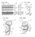
- a wire core 20 in a developed state as shown in Fig. 5 (a) is sent out from a wire carrier (w/c) providing apparatus 41.
- the wire body 21 of the wire core 20 is partially connected with four non-thermo-fusible yarns (221, 222, 223, 224) and five thermo-fusible yarns 23 in a longitudinal direction.
- the non-thermo-fusible yarns 221. are provided in advance, while the wire body 21 bent roughly in U-shape is embedded in the installation base member 11 (state of a resultant product), in the range 401 from the bending start position 21c forming the shoulder 21a on the outer-cabin side of the wire body 21 which is bent roughly in U-shape to a position 52 determined by offsetting a point 51 on the door internal circumference side of the inner-side base 12a of the hollow seal member 12 with respect to the wire body 21, avoiding the shoulder 21a on the outer-cabin side.
- the non-thermo-fusible yarns 222 are provided in advance, while the wire body 21 bent roughly in U-shape is embedded in the installation base member 11, in the range 501 from the bending start position 21e forming the shoulder 21b on the inner-cabin side of the wire body 21 which is bent roughly in U-shape to the position 54 determined by offsetting the point 53 on the opening edge side on the inner-cabin side wall 11b of the base of the protuberance 13 with respect to the wire body 21, avoiding the shoulder 21b on the inner-cabin side.
- thermo-fusible yarns 23 are provided in advance, while the wire body 21 bent roughly in U-shape is embedded in the installation base member 11.
- two thermo-fusible yarns 23 are provided on the connecting wall 11c side of the installation base member11 except for shoulders 21a, 21b;
- two thermo-fusible yarns 23 are provided on the outer-cabin side wall 11a of the installation base member 11, that is the opening edge side of the outer-cabin side wall 11a compared with the providing point of the non-thermo-fusible yarn 221 on the outer-cabin side;
- one thermo-fusible yarn 23 is provided on the inner-cabin side wall 11b of the installation base member 11, that is the opening edge side of the inner-cabin side wall 11b compared with the providing point of the non-thermo-fusible yarn 222 on the inner-cabin side.
- the non-thermo-fusible yarns 223, 224 are provided in advance, while the wire body 21 bent roughly in U-shape is embedded in the installation base member 11, on the inner-cabin side wall 11b of the installation base member 11 that is the connecting wall 11c side compared with the providing point of the non-thermo-fusible yarn 222 on the inner-cabin side.
- the wire core 20 in the developed state is bent into a dish shape in cross section by bending both edge sides thereof in a pre-bent apparatus 42 as shown in Fig. 5 (b) . Also, only one edge side (one of the two edge sides) of the wire core 20 may be bent, not both edge sides.
- an extruder 43 forms the installation base member 11 into a dish shape by further widening an opening of the installation base member 11 as shown in Fig. 5 (c) compared with the rough U-shape in cross section (the opening is widened by around 45 degrees respectively to the left and right compared with the rough U-shape in cross section) along the shape of the wire core 20 that is pre-bent into the dish shape in cross section and embedded in the installation base member 11.
- the extruder 43 extrudes the opening seal 10 for automobiles into a vulcanization furnace 44.
- the hollow seal member 12, the protuberance 13, the projections 14, the lip 15 and the coating material 16 are integrally extrusion molded with the installation base member 11.
- the vulcanization furnace 44 has a taking-out unit 45 on an exit side thereof for guiding the wire core 20 extruded from the extruder 43 together with the opening seal 10 for automobiles to the vulcanization furnace 44 with strong force.
- the opening seal 10 for automobiles is heat treated at 200 °C to 250 °C inside the vulcanization furnace 44, which vulcanizes the rubber component and assures stable elasticity and strength. While the thermo-fusible yarn 23 vanishes when passing through the vulcanization furnace 44, four non- thermo-fusible yarns 221, 222, 223, 224 do not melt even after passing through the vulcanization furnace 44. Therefore, the opening seal 10 for automobiles is not expanded in the vulcanization process.
- the vulcanized opening seal 10 for automobiles passes through a sizing die for narrowing the opening of the installation base member 11 to be the rough U-shape in cross section as shown in Fig. 5(d) .
- the installation base member 11 mounted on the flange 3 installed along the periphery of the door opening part of the body 1 has the wire core 20 embedded therein, including the skeletal wire body 21 connected with the non-thermo-fusible yarns 22 (221, 222, 223, 224) which do not melt at the set vulcanization temperature. Accordingly, while vulcanizing and extrusion molding the opening seal 10 for automobiles, the non-thermo-fusible yarns 22 remain without melting.
- Such a structure controls unnecessary expansion of the opening seal 10 for automobiles together with the wire core 20 for the effect of the non-thermo-fusible yarns 22 even in case the wire core 20 is pulled with strong force while extrusion molding the opening seal 10 for automobiles in the course of preparation. Also, the structure improves assembly force of the opening seal 10 for automobiles on the flange 3 by improving the rigidity of the installation base member 11 after molding.
- non-thermo-fusible yarns 22 are provided respectively on the outer-cabin side and the inner-cabin side.
- the non-thermo-fusible yarn 221 on the outer-cabin side is provided in the range 401 from the bending start position 21c forming the shoulder 21a on the outer-cabin side of the wire body 21 which is bent roughly in U-shape to the position 52 determined by offsetting a point 51 on the door internal circumference side of the inner-side base 12a of the hollow seal member 12 with respect to the wire body 21.
- the non-thermo-fusible yarn 222 on the inner-cabin side is provided in the range 501 from the bending start position 21e forming the shoulder 21b on the inner-cabin side of the wire body 21 which is bent roughly in U-shape to the position 54 determined by offsetting a point 53 on the opening edge side on the inner-cabin side wall 11b of the base of the protuberance 13.
- the straight line which connects the position of the non-thermo-fusible yarn 222 on the inner-cabin side and the position of the non-thermo-fusible yarn 221 on the outer-cabin side leans toward the internal circumference side of the door 2 from the outer circumference side (toward the connecting wall 11c side from the opening part side of the installation base member 11) as faced toward the outer-cabin side from the inner-cabin side.
- the leaned straight line as extended intersects the hollow seal member 12 on the position on the internal circumference side of the door 2 compared with the prior art ( Fig. 9 ) in which the leaned straight line as extended intersects hollow seal member 12 on the position on the outer circumference side (on the connecting wall 11c side from the opening part side of the installation base member 11). Accordingly, contracting force functions within the smaller domain of the hollow seal member 12 when the opening seal for automobiles is assembled on the corner part on the body side, thereby preventing generation of the folding wrinkles 202.
- Such a structure enables stable assembly of the opening seal 10 for automobiles on the corner part on the body side of the automobile and keeps the opening seal 10 for automobiles stably assembled even after the assembly.
- the leaned straight line as extended which connects the position of the non-thermo-fusible yarn 221 on the outer-cabin side and the position of the non-thermo-fusible yarn 222 on the inner-cabin side, intersects the hollow seal member 12 on the position further on the internal circumference side of the door 2, shifted from the outer circumference side (on the connecting wall 11c side shifted from the opening part side of the installation base member 11). Accordingly, the contracting force functions within the smaller domain of the hollow seal member 12 when the opening seal 10 for automobiles is assembled on the corner part on the body side of the automobile, thereby preventing generation of folding wrinkles 202.
- the fastening force of the installation base member 11 on the flange 3 from the inner-cabin side wall 11b side is increased, which enables the protuberance 13 provided on the inner-cabin side wall 11b side to hold the flange 3 sufficiently.
- non-thermo-fusible yarn 222 on the inner-cabin side is provided on the position 57 within the range 503, on which the straight line 100 connecting the position of the end 56 on the door internal circumference side on the hollow side of the hollow seal member 12 and the providing point of the non-thermo-fusible yarn 221 on the outer-cabin side intersects the inner-cabin side of the wire body 21, the straight line which connects the position of the non-thermo-fusible yarn 221 on the outer-cabin side and the position of the non-thermo-fusible yarn 222 on the inner-cabin side, as extended, intersects the hollow seal member 12 on the position which is the end 56 on the door internal circumference side on the hollow side of the hollow seal member 12.
- the contracting force functions only on thickness of the hollow seal member 12 when the opening seal 10 for automobiles is assembled on the corner part on the body side of the automobile so that the folding wrinkles 202 hardly generates.
- the non-thermo-fusible yarn 222 on the inner-cabin side is shifted from the position 57 where the straight line 100 intersects the inner-cabin side of the wire body 21 to the position 54 determined by offsetting the point 53 on the opening edge side on the inner-cabin side wall 11b of the base of the protuberance 13 with respect to the wire body 21, the straight line which connects the position of the non-thermo-fusible yarn 221 on the outer-cabin side and the position of the non-thermo-fusible yarn 222 on the inner-cabin side, as extended, intersects the hollow seal member 12 on the position, that is further on the door internal circumference side compared with the end 56 on the door internal circumference side. Accordingly, generation of the folding wrinkles is further prevented.
- the base 12a of the hollow seal member 12 which extends from an inner side position of the outer-cabin side wall 11a of the installation base member 11, is laid toward the internal circumference side of the door 2 compared with the base 12b of the hollow seal member 12, which extends from an outer side position of the outer-cabin side wall 11a.
- the inner-side base 12a of the hollow seal member 12 may project from the outer-cabin side wall 11a of the installation base member 11 at the same angle as the base 12b on the outer side, thereby extending in a rough V-shape in cross section.
- the non-thermo-fusible yarn 222 on the inner-cabin side is provided in the range 503 from the position 57 where the straight line 100 connecting the end 56 on the door internal circumference side (door internal circumference side end part) on the hollow side of the hollow seal member 12 and the providing point of the non-thermo-fusible yarn 221 on the outer-cabin side intersects the inner-cabin side of the wire body 21 to the position 54 determined by offsetting the point 53 on the opening edge side on the inner-cabin side wall 11b of the base of the protuberance 13 with respect to the wire body 21.
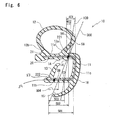
- the range 503 may be limited by narrowing. Specifically, as shown in Fig.
- non-thermo-fusible yarn 222 on the inner-cabin side may be provided in the range 504 from the position 59 where the straight line 300 connecting the end 58 on the door internal circumference side (door internal circumference side end part) of the hollow seal member 12 and the providing point of the non-thermo-fusible yarn 221 on the outer-cabin side intersects the inner-cabin side of the wire body 21 to the position 54 determined by offsetting the point 53 on the opening edge side on the inner-cabin side wall 11b of the base of the protuberance 13 with respect to the wire body 21.
- one protuberance 13 is provided inside the inner-cabin side wall 11b of the installation base member 11. But, as shown in Fig. 7 , a plurality of the protuberances 13, 17 (two protuberances in Fig. 7 ) may be provided.
- a limitation point for providing the non-thermo-fusible yarn 222 on the inner-cabin side on the opening edge side of the inner-cabin side wall 11b is the position 54 determined by offsetting the point 53, on the opening edge side on the inner-cabin side wall 11b of the base of the protuberance 13 as a benchmark among the plurality of the protuberances 13, 17 positioned on the greater opening edge part side on the inner-cabin side wall 11b of the installation base member 11, with respect to the wire body 21.
- the shoulder 21a on the outer-cabin side of the installation base member 11 is provided with coating material 31 having higher specific gravity (e.g. specific gravity of 0.9 to 1.3) compared with material forming the installation base member 11 over a wider range compared with the coating material 16. Accordingly, the opening seal 10 for automobiles is stably assembled on the on the corner part of a periphery of the door 2 opening part of the body 1 and wrinkles do not generate on the part provided with the coating material 31.
- the non-thermo-fusible yarn 221 on the inner-cabin side may be changed to the thermo-fusible yarn depending on strength of the material forming the part.
Landscapes
- Engineering & Computer Science (AREA)
- Mechanical Engineering (AREA)
- Seal Device For Vehicle (AREA)
- Extrusion Moulding Of Plastics Or The Like (AREA)
Description
- The present invention relates to opening seals for automobiles and method of preparing the same having wire core embedded in installation base members thereof for increasing rigidity, which are installed along peripheries of door opening parts of automobile bodies for sealing openings between bodies and doors by making elastic contact with the doors when the doors are closed.
- As shown in
Fig. 8 andFig. 9 , anopening seal 10 for automobiles having awire core 20 embedded therein has been well-known, which is mounted on aflange 3 installed along a periphery of adoor 2 opening part on anautomobile body 1 side for making elastic contact with thedoor 2 when thedoor 2 is closed to seal an opening between thebody 1 and the door 2 (see, for example, the Japanese unexamined Patent Publication Nos.H03-82519 2004-322768 -
Fig. 8 is a side view of an automobile having theopening seal 10 for automobiles mounted thereon; andFig. 9 is an enlarged perspective view of an important part of 100 ofFig. 8 , showing theopening seal 10 for automobiles. - The
opening seal 10 for automobiles comprises a cross section roughly U-shapedinstallation base member 11 including an outer-cabin side wall 11a, an inner-cabin side wall 11b and a connectingwall 11c which connects theside walls hollow seal member 12 provided on an outer-cabin side of theinstallation base member 11; and aprotuberance 13 provided inside the inner-cabin side wall 11b of theinstallation base member 11, which makes elastic contact with and holds theflange 3. The outer-cabin side wall 11a has a plurality ofprojections 14 provided inside, which make elastic contact with theflange 3; and theinstallation base member 11 has alip 15 provided on an inner-cabin side thereof.Decorative coating material 16 is provided from thelip 15 to a surface of the connectingwall 11c of theinstallation base member 11 for decorating appearance from an inner-cabin side. - As shown in
Fig. 10 andFig. 11 , thewire core 20 embedded in theinstallation base member 11 of theopening seal 10 for automobiles comprises: askeletal wire body 21 formed by consecutively bending a wire; andyarns wire body 21 for preventing expansion of thewire body 21 in a longitudinal direction. Thewire core 20 is finally embedded in a longitudinal direction of theinstallation base member 11 while thewire core 20, consecutively bent into U shapes in the same direction at regular intervals in advance, is bent into a rough U-shape. - Examples of use of the yarns for preventing expansion of the
wire body 21 in a longitudinal direction include: a plurality of non-thermo-fusible yarns 22 which do not melt at set vulcanization temperature for vulcanizing rubber component when preparing theopening seal 10 for automobiles as shown inFig. 9 and Fig. 10 (six non-thermo-fusible yarns inFig. 9 and Fig. 10 ); and a combination of the non-thermo-fusible yarns 22 which do not melt at the set vulcanization temperature and thermo-fusible yarns 23 which do not melt at the time of an extrusion molding and melt at the set vulcanization temperature as shown inFig. 11 (two non-thermo -fusible yarns 22 and six thermo-fusible yarns 23 inFig. 11 ). - Such a structure controls unnecessary expansion of the
opening seal 10 for automobiles at the time of the extrusion molding and the preparation of theopening seal 10 for automobiles and improves rigidity of theinstallation base member 11 after molding, thereby improving assembly force of theopening seal 10 for automobiles on theflange 3. - In the
opening seal 10 for automobiles prepared by extrusion molding, parts with the non-thermo-fusible yarn 22 are greatly improved in strength compared with parts without the non-thermo-fusible yarn 22. But, in theresultant opening seal 10 for automobiles having the full length including a corner part has caused problems that, on an outer peripheral side of aposition 201 as an intersection of thehollow seal member 12 and astraight line 200, thehollow seal member 12 is subjected to force expanding toward an outer peripheral side whereas, on an inner peripheral side of theposition 201, thehollow seal member 12 is subjected to contracting force which cause wrinkles. Thestraight line 200 connects the non-thermo-fusible yarn 22 (22a) embedded on a greater opening edge side on the outer-cabin side wall 11a of theinstallation base member 11 with the non-thermo-fusible yarn 22 (22b) embedded on a greater opening edge side on the inner-cabin side wall 11b of theinstallation base member 11. - The expansion and contraction of the
hollow seal member 12 hamper stabilization of the assembled state of theopening seal 10 for automobiles, which degrades external appearance and sealing function. Such problems are remarkable when thefolding wrinkles 202 generate. - As shown in
Fig. 11 , the Japanese unexamined Patent Publication No.H03-82519 wire core 20, respectively embedded in the outer-cabin side wall 11a, an inner-cabin side wall 11b and a connectingwall 11c of theinstallation base member 11, with the yarns which are thermally degraded at the set vulcanization temperature and the yarns which are not thermally degraded (non-thermo-fusible yarn) at the set vulcanization temperature. The resultant opening seal is excellent in strength toward pulling force at the time of extrusion molding. But a way of disposing the yarns on each of the three sides of thewire core 20 is rough, only one side of thewire core 20 with the non-thermo-fusible yarn for example. Such a structure does not decrease expanding or contracting state on thehollow seal member 12 sufficiently, especially while theopening seal 10 for automobiles is assembled on the corner part. - The Japanese unexamined Patent Publication No.
2004-322768 cabin side wall 11b, that is at least close to the connectingwall 11c. But the invention relates to weather strips installed on automobile bodies with curves which are swelled toward width direction of the automobiles. Accordingly, the invention does not decrease expanding or contracting state on thehollow seal member 12 sufficiently while theopening seal 10 for automobiles is assembled on the corner part. - Therefore, an object of the present invention is to provide the opening seal for automobiles and method of preparing the same capable of remarkably decreasing the expanding or contracting state on the hollow seal member while the opening seal for automobiles is assembled on the corner part.
- In order to achieve the above-mentioned object, a first aspect of the invention provides an opening seal for automobiles, comprising: an installation base member (11) with a roughly U-shaped cross section mountable on a flange (3) installed along a periphery of a door (2) opening which is part of a vehicle body (1), the base member including an outer-cabin side wall (11a), an inner-cabin side wall (11b) and a connecting wall (11c) connecting the side walls (11a, 11b);
a hollow seal member (12) extending from an inner side position (301) and an outer side position (800) of said outer-cabin side wall (11a) of the installation base member (11) respectively toward an internal circumference side (305) and an outer circumference side (304) of a door, which is swelled and curved toward an outer-cabin side (304) for making elastic contact with said door (2) thereby sealing an inside and an outside of the automobile;
one or a plurality of protuberances (13) installed inside the inner-cabin side wall (11b) of said installation base member (11) for making elastic contact with and holding said flange (3); and
a wire core (20) embedded in a longitudinal direction of said installation base member (11) while being bent roughly in U-shape, including:
a skeletal wire body (21) formed by continuously bending a wire; and non-thermo-fusible yarn which does not melt at set vulcanization temperature, which is partially connected with the wire body (21) and is roughly linearly extending in a longitudinal direction while controlling expansion of the wire body (21) in a longitudinal direction; wherein
said wire core (20) has at least two non-thermo-fusible yarns (22) respectively provided on the outer-cabin side (306) and the inner-cabin side (307) thereof,
the non-thermo-fusible yarn (221) on the outer-cabin side is provided in a range (401) from a bending start position (21c) forming a shoulder (21a) on the outer-cabin side of the wire body (21) which is bent roughly in U-shape to a position (52) determined by offsetting a point (51), on the door internal circumference side (305) of an inner-side base (12a) of said hollow seal member (12), with respect to the wire body (21); and
the non-thermo-fusible yarn (222) on the inner-cabin side is provided in a range (501) from a bending start position (21e) forming a shoulder (21b) on the inner-cabin side of the wire body (21) which is bent roughly in U-shape, to a position (54) determined by offsetting a point (53), on an opening edge side (308) on said inner-cabin side wall (11b) of a base of the protuberance (13) which is positioned on a greater opening edge part side (309) on the inner-cabin side wall (11b) of said installation base member (11) among said one or a plurality of protuberances (13), with respect to the wire body (21). - A second aspect of the invention provides the opening seal for automobiles according to the first aspect of the invention, wherein: said non-thermo-fusible yarn (221) on the outer-cabin side (306) is provided in a range (402) from a bending end position (21d) forming a shoulder (21a) on the outer-ca.bin side of the wire body (21) which is bent roughly in U-shape to a position (52) determined by offsetting a point (51), on the door internal circumference side (305) of an inner-side base (12a) of said hollow seal member (12), with respect to the wire body (21).
- A third aspect of the invention provides the opening seal for automobiles according to the first or second aspect of the invention, wherein: said non-thermo-fusible yarn (222) on the inner-cabin side (307) is provided in a range (502) from a position (55) on the inner-cabin side determined by offsetting a provided point of said non-thermo-fusible yarn (221) on the outer-cabin side (306) with respect to the wire body (21) to a position (54) determined by offsetting a point (53), on an opening edge side on said inner-cabin side wall (11b) of a base of the protuberance (13) that is positioned on the greater opening edge part side on the inner-cabin side wall (11b) of said installation base member (11) among said one or a plurality of protuberances, with respect to the wire body (21).
- A fourth aspect of the invention provides the opening seal for automobiles according to the second aspect of the invention, wherein: said non-thermo-fusible yarn (222) on the inner-cabin side is provided in a range (503) from a position (57), where a straight line (100) connecting a point (56) on the door internal circumference side (305) on an internal side of the wall of said hollow seal member (12) and a provided point of said non-thermo-fusible yarn (221) on the outer-cabin side intersects the inner-cabin side of the wire body (21), to the position (54) determined by offsetting the point (53), on the opening edge side on said inner-cabin side wall (11b) of the base of the protuberance (13) that is positioned on the greater opening edge part side on the inner-cabin side wall (11b) of said installation base member (11) among said one or a plurality of protuberances, with respect to the wire body (21).
- A fifth aspect of the invention provides the opening seal for automobiles according to the second aspect of the invention, wherein: said non-thermo-fusible yarn (222) on the inner-cabin side is provided in a range (504) from a position (59), where a straight line (300) connecting a point (58) on the door internal circumference side (305) of an outer side of the wall of said hollow seal member (12) and a provided point of said non-thermo-fusible yarn (221) on the outer-cabin side intersects the inner-cabin side of the wire body (21), to the position (54) determined by offsetting the point (53), on the opening edge side on said inner-cabin side wall (11b) of the base of the protuberance (13) that is positioned on the greater opening edge part side on the inner-cabin side wall (11b) of said installation base member (11) among said one or a plurality of protuberances, with respect to the wire body (21).
- An sixth aspect of the invention provides the opening seal for automobiles according to any one of the first to fifth aspects of the invention, wherein: the shoulder (21a) on the outer-cabin side of said installation base member (11) is provided with coating material (31) having higher specific gravity compared with material forming said installation base member (11).
- Symbols in parentheses show constituents or items corresponding to Figures and DESCRIPTION OF PREFERRED EMBODIMENT.
- With the opening seal for automobiles and the method of preparing the same of the present invention, the installation base member mounted on the flange installed along the periphery of the door opening part of the body has the wire core embedded therein, including the skeletal wire body connected with the non-thermo-fusible yarn which does not melt at set vulcanization temperature. Accordingly, in a course of vulcanization and extrusion molding the opening seal for automobiles, the non-thermo-fusible yarn remains, not melts. Such a structure controls unnecessary expansion of the opening seal for automobiles together with the wire core for the effect of the non-thermo-fusible yarns even in case the wire core is pulled with strong force while extrusion molding the opening seal for automobiles in the course of preparation. Also, the structure improves assembly force of the opening seal for automobiles on the flange by improving the rigidity of the installation base member after molding.
- In addition, the wire core has at least two non-thermo-fusible yarns respectively provided on the outer-cabin side and the inner-cabin side thereof; the non-thermo-fusible yarn on the outer-cabin side is provided in the range from the bending start position forming the shoulder on the outer-cabin side of the wire body which is bent roughly in U-shape to the position determined by offsetting the point, on the door internal circumference side of an inner-side base of the hollow seal member, with respect to the wire body; and the non-tbermo-fusible yarn on the inner-cabin side is provided in the range from the bending start position forming the shoulder on the inner-cabin side of the wire body which is bent roughly in U-shape to the position determined by offsetting the point, on the opening edge side on said inner-cabin side wall of a base of the protuberance which is positioned on the greater opening edge part side on the inner-cabin side wall of the installation base member, with respect to the wire body. The straight line which connects the position of the non-thermo-fusible yarn on the outer-cabin side and the position of the non-thermo-fusible yarn on the inner-cabin side leans toward the internal circumference side from the outer circumference side of a door (toward the connecting wall side from an opening part side of the installation base member) when the door is closed as faced toward the outer-cabin side from the inner-cabin side for the effect of the non-thermo-fusible yarn on the outer-cabin side thus provided.
- The leaned straight line as extended intersects the hollow seal member on a position on the internal circumference side of a door (on the connecting wall side from the opening part side of the installation base member) compared with the prior art (
Fig. 9 ) in which the leaned straight line as extended intersects hollow seal member on a position on the outer circumference side. Accordingly, contracting force functions within a smaller domain of the hollow seal member when the opening seal for automobiles is assembled on a corner part on the body side of the automobile, thereby preventing generation of folding wrinkles. - Further, by leaning the straight line which connects the position of the non-thermo-fusible yarn on the outer-cabin side and the position of the non-thermo-fusible yarn on the inner-cabin side, fastening force of the installation base member on the flange from the inner-cabin side wall side is increased, which enables the protuberance provided on the inner-cabin side wall side to hold the flange sufficiently.
- Such a structure enables stable assembly of the opening seal for automobiles on the corner part on the body side of the automobile and keeps the opening seal stably assembled after the assembly.
- In addition, according to the present invention, the non-thermo-fusible yarn on the outer-cabin side is provided from the bending end position, not bending start position forming the shoulder on the outer-cabin side of the wire body which is bent roughly in U-shape. Accordingly, the non-thermo-fusible yarn on the outer-cabin side is provided on the outer-cabin side wall side of the installation base member, changed from the connecting wall side. Such a structure improves balance when connecting the wire body and effectively controls unnecessary expansion of the opening seal for automobiles together with the wire core while the opening seal for automobiles together with the non-thermo-fusible yarn on the inner-cabin side is extrusion molded.
- In addition, according to the present invention, the non-thermo-fusible yarn on the inner-cabin side is provided in a further limited range: from the position on the inner-cabin side, determined by offsetting the providing point of the non-thermo-fusible yarn on the outer-cabin side with respect to the wire body; from the position where the straight line connecting the end on the door internal circumference side on the hollow side of the hollow seal member and the providing point of the non-thermo-fusible yarn on the outer-cabin side intersects the inner-cabin side of the wire body; or from the position where the straight line connecting the end on the door internal circumference side of the hollow seal member and the providing point of the non-thermo-fusible yarn on the outer-cabin side intersects the inner-cabin side of the wire body. The leaned straight line as extended intersects the hollow seal member on a position on the internal circumference side of the door, changed from the outer circumference side, that is on the connecting wall side changed from the opening part side of the installation base member. Accordingly, the contracting force functions within a further smaller domain of the hollow seal member when the opening seal for automobiles is assembled on the corner part on the body side, thereby preventing generation of folding wrinkles.
- Also, the fastening force of the installation base member on the flange from the inner-cabin side wall side is increased, which enables the protuberance provided on the inner-cabin side wall side to hold the flange sufficiently.
- It is to be noted that the position on the opening edge side of the inner-cabin side wall of each range (501, 502, 503, 504 according to the following embodiment) is determined by offsetting the point, on the opening edge side on the inner-cabin side wall of the base of the protuberance that is positioned on the greater opening edge part side on the inner-cabin side wall of the installation base member among the one or plurality of protuberance, with respect to the wire body. In case the position on the opening edge side is further on the opening edge side compared with the above-mentioned position, the opening seal for automobiles in itself may lean when assembled on the corner part on the automobile body side, which is not a desired assembled state and not favorable.
- In case the non-thermo-fusible yarn on the inner-cabin side is provided in the range from the position where the straight line connecting the end on the door internal circumference side of the hollow seal member and the providing point of the non-thermo-fusible yarn on the outer-cabin side intersects the inner-cabin side of the wire body to the position determined by offsetting the point on the opening edge side on the inner-cabin side wall of the base of the protuberance that is positioned on the greater opening edge part side on the inner-cabin side wall of the installation base member among the one or plurality of protuberance with respect to the wire body, the straight line which connects the position of the non-thermo-fusible yarn on the outer-cabin side and the position of the non-thermo-fusible yarn on the inner-cabin side, as extended, intersects the hollow seal member on the position which is the end on the door internal circumference side of the hollow seal member or further door internal circumference side. Accordingly, the contracting force does not function on the hollow seal member when the opening seal for automobiles is assembled on the corner part on the body side of the automobile.
- In case the non-thermo-fusible yarn on the inner-cabin side is provided on the position on which the straight line connecting the end on the door internal circumference side on the hollow side of the hollow seal member and the providing point of the non-thermo-fusible yarn on the outer-cabin side intersects the inner-cabin side of the wire body, the straight line which connects the position of non-thermo-fusible yarn on the outer-cabin side and the position of the non-thermo-fusible yarn on the inner-cabin side, as extended, intersects the hollow seal member on the position which is the end on the door internal circumference side on the hollow side of the hollow seal member when the door is closed. Accordingly, the contracting force functions only on thickness of the hollow seal member when the opening seal for automobiles is assembled on the corner part on the body side of the automobile so that the folding wrinkles hardly generates. In case the non-thermo-fusible yarn on the inner-cabin side is shifted from the position where the straight line connecting the end on the door internal circumference side on the hollow side of the hollow seal member and the providing point of the non-thermo-fusible yarn on the outer-cabin side intersects the inner-cabin side of the wire body to a position determined by offsetting the point on the opening edge side on the inner-cabin side wall of the base of the protuberance that is positioned on the greater opening edge part side on the inner-cabin side wall of the installation base member among the one or the plurality of protuberance with respect to the wire body, the straight line which connects the position of the non-thermo-fusible yarn on the outer-cabin side and the position of the non-thermo-fusible yarn on the inner-cabin side, as extended, intersects the hollow seal member on the position which is further door internal circumference side compared with the end on the door internal circumference side on the hollow side of the hollow seal member when the door is closed. Accordingly, generation of the folding wrinkles is further prevented.
- In addition, according to the present invention, the wire body is partially connected with thermo-fusible yarn as well as the non-thermo-fusible yarn, which melts at set vulcanization temperature and roughly linearly extends in the longitudinal direction. Accordingly, the wire body is resistant to the pulling force before vulcanization. Also, the thermo-fusible yarn is provided on the connecting wall of the installation base member, on the outer-cabin side wall of the installation base member that is the opening edge side of the outer-cabin side wall compared with the providing point of the non-thermo-fusible yarn on the outer-cabin side and on the inner-cabin side wall of the installation base member that is the opening edge side of the inner-cabin side wall compared with the providing point of the non-thermo-fusible yarn on the inner-cabin side. Accordingly, the opening seal for automobiles is well-balanced and the thermo-fusible yarn that vanishes for the vulcanization does not cause expansion and contraction of the hollow seal member when the opening seal for automobiles is assembled on the corner part on the automobile body side.
- In addition, according to the present invention, the shoulder on the outer-cabin side of the installation base member is provided with coating material having higher specific gravity compared with material forming the installation base member. Accordingly, the opening seal for automobiles is stably assembled on the corner part on the automobile body side and wrinkles do not generate on a part provided with the coating material. The non-thermo-fusible yarn on the inner-cabin side may be changed to the thermo-fusible yarn depending on strength of the material on the part.
-
-
Fig. 1 is a cross section showing an opening seal for automobiles according to an embodiment of the present invention; -
Figs. 2 show a wire core shown inFig. 1 , of which (a) is a plan view showing a state before the wire core is bent and (b) is a cross section showing a state after the wire core is bent; -
Fig. 3 is a cross section showing an opening seal for automobiles according to another embodiment of the present invention; -
Fig. 4 is a block diagram showing a process of preparing the opening seal for automobiles ofFig. 3 ; -
Figs. 5 show each state of the opening seal for automobiles in each section ofFig. 4 , of which (a) are a plan view and a cross section of the wire core inSection 601, (b) is a cross section of the wire core inSection 602, (c) is a cross section of the opening seal for automobiles inSection 603 and (d) is a cross section of the opening seal for automobiles inSection 604; -
Fig. 6 is a cross section showing an opening seal for automobiles according to still another embodiment of the present invention; -
Fig. 7 is a cross section showing an opening seal for automobiles according to still another embodiment of the present invention; -
Fig. 8 is an external side view of an automobile; -
Fig. 9 is an enlarged perspective view of partial cross section of 100 inFig. 8 , showing a state that an opening seal for automobiles according to a prior art is mounted; -
Figs. 10 show a state before a wire core embedded in the opening seal for automobiles ofFig. 9 is bent, of which (a) is a plan view and (b) is a cross section; and -
Fig. 11 show a state before another wire core embedded in the opening seal for automobiles ofFig. 9 is bent, of which (a) is a plan view and (b) is a cross section. - Referring to
Fig. 1 andFig. 2 , anopening seal 10 for automobiles according to an embodiment of the present invention will be described.Fig. 1 is a cross section showing anopening seal 10 for automobiles according to an embodiment of the present invention andFig. 2 shows a cross section of awire core 20 shown inFig. 1 . When constituents or items correspond to those in prior arts, the same symbols are used. - The
opening seal 10 for automobiles according to the embodiment of the present invention mainly comprises: aninstallation base member 11; ahollow seal member 12; aprotuberance 13; and awire core 20. - The
installation base member 11 is cross section roughly U-shaped, including an outer-cabin side wall 11a, an inner-cabin side wall 11b and a connectingwall 11c connecting theside walls Fig. 8 andFig. 9 , theinstallation base member 11 is installed on aflange 3 installed along a periphery of adoor 2 opening part of abody 1 in such a manner that theflange 3 is inserted into theinstallation base member 11 from an opening part side. Theflange 3 extends inward along the periphery of thedoor 2 opening part. -
Bases hollow seal member 12 extend from an inner side position and an outer side position of the outer-cabin side wall 11a of theinstallation base member 11 respectively toward an internal circumference side and an outer circumference side of a door, which is swelled and curved toward an outer-cabin side. Thehollow seal member 12 makes elastic contact with thedoor 2 and seals an inside and an outside of the automobile when thedoor 2 is closed. - The
protuberance 13 extends from an inside (outer-cabin side) of the inner-cabin side wall 11b of theinstallation base member 11 toward the connecting wall 11e side. Theprotuberance 13, together with the a plurality of (two in the present embodiment)projections 14 provided inside the outer-cabin side wall 11a of theinstallation base member 11, makes elastic contact with and holds theflange 3 by clasping. Theinstallation base member 11 has alip 15 provided on an inner-cabin side thereof.Decorative coating material 16 is provided from thelip 15 to a surface of the connectingwall 11c of theinstallation base member 11 for decorating appearance from an inner-cabin side. - As shown in
Fig. 2 (a) , awire core 20 comprises: askeletal wire body 21 formed by consecutively bending a wire; andyarn 22 partially connected with thewire body 21 for preventing expansion of thewire body 21 in a longitudinal direction. As shown inFig. 2 (b) , thewire core 20 is finally embedded in a longitudinal direction of theinstallation base member 11 while thewire core 20, consecutively bent in U shapes in the same direction at regular intervals in advance, is bent into a rough U-shape by bending ashoulder 21a on the outer-cabin side and ashoulder 21b on the inner-cabin side. 21c is a bending start position forming theshoulder 21a on the outer-cabin side and 21d is a bending end position forming theshoulder 21a on the outer-cabin side. In the same manner, 21e is a bending start position forming ashoulder 21b on the inner-cabin side and 21f is a bending end position forming ashoulder 21b on the inner-cabin side. -
Yarn 22 for controlling expansion of thewire body 21 in a longitudinal direction is non-thermo-fusible yarn which does not melt at set vulcanization temperature for vulcanizing rubber component in the course of preparing theopening seal 10 for automobiles. Two non-thermo-fusible yarns - Positions for providing the non-thermo-
fusible yarn 221. on the outer-cabin side and the non-thermo-fusible yarn 222 on the inner-cabin side are defined as follows. - As shown in
Fig. 1 , the non-thermo-fusible yarn 221. on the outer-cabin side is provided, while thewire body 21 bent roughly in U-shape is embedded in theinstallation base member 11, in arange 401 from the bendingstart position 21c forming theshoulder 21a on the outer-cabin side of thewire body 21 which is bent roughly in U-shape to aposition 52 determined by offsetting apoint 51 on the door internal circumference side of the inner-side base 12a of thehollow seal member 12 with respect to thewire body 21. In case the non-thermo-fusible yarn 221 is positioned on theshoulder 21a on the outer-cabin side, the non-thermo-fusible yarn 221 is subjected to shift when bending thewire body 21 as shown inFig. 2 (b) from a developed state shown inFig. 2 (a) . Therefore, it is preferable not to position the non-thermo-fusible yarn 221 on theshoulder 21a on the outer-cabin side. Accordingly the non-thermo-fusible yarn 221 on the outer-cabin side may also be provided in arange 402 from the bendingend position 21d forming theshoulder 21a on the outer-cabin side of thewire body 21 which is bent roughly in U-shape to theposition 52 determined by offsetting thepoint 51 on the door internal circumference side of the inner-side base 12a of thehollow seal member 12 with respect to thewire body 21. - In case the non-thermo-
fusible yarn 221 on the outer-cabin side is provided from the bendingend position 21d, not the bendingstart position 21c forming theshoulder 21a on the outer-cabin side of thewire body 21 which is bent roughly in U-shape, the non-thermo-fusible yarn 221 on the outer-cabin side is provided on the outer-cabin side wall 11a side of theinstallation base member 11, changed from the connectingwall 11c side. Such a structure improves balance when connecting thewire body 21 and effectively controls unnecessary expansion of theopening seal 10 for automobiles together with thewire core 20 while theopening seal 10 for automobiles as well as the non-thermo-fusible yarn 222 on the inner-cabin side is extrusion molded. - As shown in
Fig. 1 , the non-thermo-fusible yarn 222 on the inner-cabin side is provided, while thewire body 21 bent roughly in U-shape is embedded in theinstallation base member 11, in arange 501 from the bendingstart position 21e forming theshoulder 21b on the inner-cabin side of thewire body 21 which is bent roughly in U-shape to aposition 54 determined by offsetting apoint 53 on an opening edge side on the inner-cabin side wall 11b of a base of theprotuberance 13 which is positioned on a greater opening edge part side on the inner-cabin side wall 11b of theinstallation base member 11, theprotuberance 13 in the present embodiment because only one protuberance is provided, with respect to thewire body 21. In case the non-thermo-fusible yarn 222 is positioned on theshoulder 21b on the inner-cabin side, the non-thermo-fusible yarn 222 is subjected to shift when bending thewire body 21 as shown inFig. 2 (b) from the developed state shown inFig. 2 (a) . Therefore, it is preferable not to position the non-thermo-fusible yarn 222 on theshoulder 21b on the inner-cabin side. Accordingly, the non-thermo-fusible yarn 222 on the inner-cabin side may also be provided in a range from the bendingend position 21f forming theshoulder 21b on the inner-cabin side of thewire body 21 which is bent roughly in U-shape to theposition 54 determined by offsetting thepoint 53 on the opening edge side on the inner-cabin side wall 11b of the base of theprotuberance 13 with respect to thewire body 21. - In case the non-thermo-
fusible yarn 222 on the inner-cabin side is provided from the bendingend position 21f, not bendingstart position 21e, forming the shoulder21b on the inner-cabin side of thewire body 21 which is bent roughly in U-shape, the non-thermo-fusible yarn 222 on the inner-cabin side is provided on the inner-cabin side wall 11b side of theinstallation base member 11, changed from the connectingwall 11c side. Such a. structure improves balance when connecting thewire body 21 and effectively controls unnecessary expansion of theopening seal 10 for automobiles together with thewire core 20 while theopening seal 10 for automobiles as well as the non-thermo-fusible yarn 221 on the outer-cabin side is extrusion molded. - The non-thermo-
fusible yarn 222 on the inner-cabin side may be provided in arange 502, which is limited by narrowing therange 501, from a position 55 on the inner-cabin side, determined by offsetting the providing point of the non-thermo-fusible yarn 221 on the outer-cabin side with respect to thewire body 21, to aposition 54 determined by offsetting thepoint 53 on the opening edge side on the inner-cabin side wall 11b of the base of theprotuberance 13 with respect to thewire body 21. - The non-thermo-
fusible yarn 222 on the inner-cabin side may be provided in arange 503, which is limited by narrowing therange 502, from aposition 57 where astraight line 100 connecting anend 56 on the door internal circumference side (door internal circumference side end part) on a hollow side of thehollow seal member 12 and the providing point of the non-thermo-fusible yarn 221 on the outer-cabin side intersects the inner-cabin side of thewire body 21 to theposition 54 determined by offsetting thepoint 53 on the opening edge side on the inner-cabin side wall 11b of the base of theprotuberance 13 with respect to thewire body 21. - As shown in
Fig. 3 , in addition to the non-thermo-fusible yarn 221 on the outer-cabin side and the non-thermo-fusible yarn 222 on the inner-cabin side, thewire body 21 may be partially connected with thermo-fusible yarn 23 which melts at the set vulcanization temperature and roughly linearly extends in a longitudinal direction. In the present embodiment, five thermo-fusible yarns 23 are provided while thewire body 21 bent roughly in U-shape is embedded in theinstallation base member 11. Specifically, two thermo-fusible yarns 23 are provided on the connectingwall 11c side of theinstallation base member 11 except for theshoulders fusible yarns 23 are provided on the outer-cabin side wall 11a of theinstallation base member 11, that is the opening edge side of the outer-cabin side wall 11a compared with the providing point of the non-thermo-fusible yarn 221 on the outer-cabin side; and one thermo-fusible yarn 23 is provided on the inner-cabin side wall 11b of theinstallation base member 11, that is the opening edge side of the inner-cabin side wall 11b compared with the providing point of the non-thermo-fusible yarn 222 on the inner-cabin side. - Also, the non-thermo-
fusible yarn 22 can be further added. InFig. 3 , two non-thermo-fusible yarns cabin side wall 11b of theinstallation base member 11 that is the connectingwall 11c side compared with the providing point of the non-thermo-fusible yarn 222 on the inner-cabin side for improving strength toward pulling force. - According to the structure, in addition to the non-thermo-
fusible yarn 22, thewire body 21 is partially connected with thermo-fusible yarn 23 which melts at the set vulcanization temperature and roughly linearly extends in a longitudinal direction. Therefore, thewire body 21 is resistant to strong pulling force before vulcanization. Also, the thermo-fusible yarn 23 is provided on each of the three sides of the installation base member. Accordingly, theopening seal 10 for automobiles is well-balanced and the thermo-fusible yarn 23 that vanishes for the vulcanization does not cause contraction of thehollow seal member 12 when theopening seal 10 for automobiles is assembled on the corner part on the automobile body side. - Examples of the non-thermo-fusible yarn 22 (221, 222, 223, 224) include yarns made of polyester resin (e.g. PET (polyethylene terephthalate)), and polyamide resin (e.g. 6 nylon, 6-6 nylon), of which melting point is 230°C to 280 °C and which do not melt during the extrusion molding (around 100°C ) nor in a vulcanization furnace (200°C to 250°C).
- Examples of the thermo-
fusible yarn 23 include yarns made of polyolefin resin (e.g. PP (polypropylene), PE (polyethylene)) of which melting point is 100 °C to 160 °C, which do not melt during the extrusion molding (around 100 °C) but melts in the vulcanization furnace (200 °C to 250 °C). - The
opening seal 10 for automobiles is made of rubber material including EPDM but may also be made of other rubber materials. Also, a sealing surface side of thehollow seal member 12 is made of sponge material (e.g. EPDM sponge) whereas other parts of the of thehollow seal member 12 are made of solid material (e.g. EPDM solid) but the materials are not especially limited. - Referring to
Fig. 4 andFig. 5 , an example of method of preparing theopening seal 10 for automobiles shown inFig. 3 is explained. - In a wire carrier (w/c) providing process, a
wire core 20 in a developed state as shown inFig. 5 (a) is sent out from a wire carrier (w/c) providingapparatus 41. Thewire body 21 of thewire core 20 is partially connected with four non-thermo-fusible yarns (221, 222, 223, 224) and five thermo-fusible yarns 23 in a longitudinal direction. - As mentioned above and shown in
Fig. 3 andFig. 5 (d) , the non-thermo-fusible yarns 221. are provided in advance, while thewire body 21 bent roughly in U-shape is embedded in the installation base member 11 (state of a resultant product), in therange 401 from the bendingstart position 21c forming theshoulder 21a on the outer-cabin side of thewire body 21 which is bent roughly in U-shape to aposition 52 determined by offsetting apoint 51 on the door internal circumference side of the inner-side base 12a of thehollow seal member 12 with respect to thewire body 21, avoiding theshoulder 21a on the outer-cabin side. - In addition, as mentioned above and shown in
Fig. 3 andFig. 5 (d) , the non-thermo-fusible yarns 222 are provided in advance, while thewire body 21 bent roughly in U-shape is embedded in theinstallation base member 11, in therange 501 from the bendingstart position 21e forming theshoulder 21b on the inner-cabin side of thewire body 21 which is bent roughly in U-shape to theposition 54 determined by offsetting thepoint 53 on the opening edge side on the inner-cabin side wall 11b of the base of theprotuberance 13 with respect to thewire body 21, avoiding theshoulder 21b on the inner-cabin side. - In addition, as mentioned above and shown in
Fig. 3 andFig. 5 (d) , five thermo-fusible yarns 23 are provided in advance, while thewire body 21 bent roughly in U-shape is embedded in theinstallation base member 11. Specifically, two thermo-fusible yarns 23 are provided on the connectingwall 11c side of the installation base member11 except forshoulders fusible yarns 23 are provided on the outer-cabin side wall 11a of theinstallation base member 11, that is the opening edge side of the outer-cabin side wall 11a compared with the providing point of the non-thermo-fusible yarn 221 on the outer-cabin side; and one thermo-fusible yarn 23 is provided on the inner-cabin side wall 11b of theinstallation base member 11, that is the opening edge side of the inner-cabin side wall 11b compared with the providing point of the non-thermo-fusible yarn 222 on the inner-cabin side. - In addition, as mentioned above and shown in
Fig. 3 andFig. 5 (d), the non-thermo-fusible yarns wire body 21 bent roughly in U-shape is embedded in theinstallation base member 11, on the inner-cabin side wall 11b of theinstallation base member 11 that is the connectingwall 11c side compared with the providing point of the non-thermo-fusible yarn 222 on the inner-cabin side. - Next, in a pre-bent process, the
wire core 20 in the developed state is bent into a dish shape in cross section by bending both edge sides thereof in apre-bent apparatus 42 as shown inFig. 5 (b) . Also, only one edge side (one of the two edge sides) of thewire core 20 may be bent, not both edge sides. - Next, in an extrusion process, an
extruder 43 forms theinstallation base member 11 into a dish shape by further widening an opening of theinstallation base member 11 as shown inFig. 5 (c) compared with the rough U-shape in cross section (the opening is widened by around 45 degrees respectively to the left and right compared with the rough U-shape in cross section) along the shape of thewire core 20 that is pre-bent into the dish shape in cross section and embedded in theinstallation base member 11. Then, in the extrusion process, theextruder 43 extrudes theopening seal 10 for automobiles into avulcanization furnace 44. In the extrusion process, thehollow seal member 12, theprotuberance 13, theprojections 14, thelip 15 and thecoating material 16 are integrally extrusion molded with theinstallation base member 11. - The
vulcanization furnace 44 has a taking-outunit 45 on an exit side thereof for guiding thewire core 20 extruded from theextruder 43 together with theopening seal 10 for automobiles to thevulcanization furnace 44 with strong force. - In the vulcanization process, the
opening seal 10 for automobiles is heat treated at 200 °C to 250 °C inside thevulcanization furnace 44, which vulcanizes the rubber component and assures stable elasticity and strength. While the thermo-fusible yarn 23 vanishes when passing through thevulcanization furnace 44, four non- thermo-fusible yarns vulcanization furnace 44. Therefore, theopening seal 10 for automobiles is not expanded in the vulcanization process. - In a forming
machine 46, the vulcanized openingseal 10 for automobiles passes through a sizing die for narrowing the opening of theinstallation base member 11 to be the rough U-shape in cross section as shown inFig. 5(d) . - Finally, after cooling treatment or the like,
resultant opening seal 10 for automobiles is prepared. - According to the above-structured
opening seal 10 for automobiles, theinstallation base member 11 mounted on theflange 3 installed along the periphery of the door opening part of thebody 1 has thewire core 20 embedded therein, including theskeletal wire body 21 connected with the non-thermo-fusible yarns 22 (221, 222, 223, 224) which do not melt at the set vulcanization temperature. Accordingly, while vulcanizing and extrusion molding theopening seal 10 for automobiles, the non-thermo-fusible yarns 22 remain without melting. Such a structure controls unnecessary expansion of theopening seal 10 for automobiles together with thewire core 20 for the effect of the non-thermo-fusible yarns 22 even in case thewire core 20 is pulled with strong force while extrusion molding theopening seal 10 for automobiles in the course of preparation. Also, the structure improves assembly force of theopening seal 10 for automobiles on theflange 3 by improving the rigidity of theinstallation base member 11 after molding. - In addition, at least two non-thermo-
fusible yarns 22 are provided respectively on the outer-cabin side and the inner-cabin side. The non-thermo-fusible yarn 221 on the outer-cabin side is provided in therange 401 from the bendingstart position 21c forming theshoulder 21a on the outer-cabin side of thewire body 21 which is bent roughly in U-shape to theposition 52 determined by offsetting apoint 51 on the door internal circumference side of the inner-side base 12a of thehollow seal member 12 with respect to thewire body 21. The non-thermo-fusible yarn 222 on the inner-cabin side is provided in therange 501 from the bendingstart position 21e forming theshoulder 21b on the inner-cabin side of thewire body 21 which is bent roughly in U-shape to theposition 54 determined by offsetting apoint 53 on the opening edge side on the inner-cabin side wall 11b of the base of theprotuberance 13. Accordingly, the straight line which connects the position of the non-thermo-fusible yarn 222 on the inner-cabin side and the position of the non-thermo-fusible yarn 221 on the outer-cabin side leans toward the internal circumference side of thedoor 2 from the outer circumference side (toward the connectingwall 11c side from the opening part side of the installation base member 11) as faced toward the outer-cabin side from the inner-cabin side. - The leaned straight line as extended intersects the
hollow seal member 12 on the position on the internal circumference side of thedoor 2 compared with the prior art (Fig. 9 ) in which the leaned straight line as extended intersectshollow seal member 12 on the position on the outer circumference side (on the connectingwall 11c side from the opening part side of the installation base member 11). Accordingly, contracting force functions within the smaller domain of thehollow seal member 12 when the opening seal for automobiles is assembled on the corner part on the body side, thereby preventing generation of thefolding wrinkles 202. - Further, by leaning the straight line which connects the position of the non-thermo-
fusible yarn 221 on the outer-cabin side and the position of the non-thermo-fusible yarn 222 on the inner-cabin side, fastening force of theinstallation base member 11 on theflange 3 from the inner-cabin side wall 11b side is increased, which enables theprotuberance 13 provided on the inner-cabin side wall 11b side to hold theflange 3 sufficiently. - Such a structure enables stable assembly of the
opening seal 10 for automobiles on the corner part on the body side of the automobile and keeps theopening seal 10 for automobiles stably assembled even after the assembly. - By gradually limiting the range for providing the non-thermo-
fusible yarn 222 on the inner-cabin side from therange 501 to 502, 503, the leaned straight line as extended, which connects the position of the non-thermo-fusible yarn 221 on the outer-cabin side and the position of the non-thermo-fusible yarn 222 on the inner-cabin side, intersects thehollow seal member 12 on the position further on the internal circumference side of thedoor 2, shifted from the outer circumference side (on the connectingwall 11c side shifted from the opening part side of the installation base member 11). Accordingly, the contracting force functions within the smaller domain of thehollow seal member 12 when theopening seal 10 for automobiles is assembled on the corner part on the body side of the automobile, thereby preventing generation offolding wrinkles 202. - Also, the fastening force of the
installation base member 11 on theflange 3 from the inner-cabin side wall 11b side is increased, which enables theprotuberance 13 provided on the inner-cabin side wall 11b side to hold theflange 3 sufficiently. - In case the non-thermo-
fusible yarn 222 on the inner-cabin side is provided on theposition 57 within therange 503, on which thestraight line 100 connecting the position of theend 56 on the door internal circumference side on the hollow side of thehollow seal member 12 and the providing point of the non-thermo-fusible yarn 221 on the outer-cabin side intersects the inner-cabin side of thewire body 21, the straight line which connects the position of the non-thermo-fusible yarn 221 on the outer-cabin side and the position of the non-thermo-fusible yarn 222 on the inner-cabin side, as extended, intersects thehollow seal member 12 on the position which is theend 56 on the door internal circumference side on the hollow side of thehollow seal member 12. Accordingly, the contracting force functions only on thickness of thehollow seal member 12 when theopening seal 10 for automobiles is assembled on the corner part on the body side of the automobile so that thefolding wrinkles 202 hardly generates. In case the non-thermo-fusible yarn 222 on the inner-cabin side is shifted from theposition 57 where thestraight line 100 intersects the inner-cabin side of thewire body 21 to theposition 54 determined by offsetting thepoint 53 on the opening edge side on the inner-cabin side wall 11b of the base of theprotuberance 13 with respect to thewire body 21, the straight line which connects the position of the non-thermo-fusible yarn 221 on the outer-cabin side and the position of the non-thermo-fusible yarn 222 on the inner-cabin side, as extended, intersects thehollow seal member 12 on the position, that is further on the door internal circumference side compared with theend 56 on the door internal circumference side. Accordingly, generation of the folding wrinkles is further prevented. - In the present embodiment, the
base 12a of thehollow seal member 12, which extends from an inner side position of the outer-cabin side wall 11a of theinstallation base member 11, is laid toward the internal circumference side of thedoor 2 compared with the base 12b of thehollow seal member 12, which extends from an outer side position of the outer-cabin side wall 11a. But, as shown inFig. 6 , the inner-side base 12a of thehollow seal member 12 may project from the outer-cabin side wall 11a of theinstallation base member 11 at the same angle as the base 12b on the outer side, thereby extending in a rough V-shape in cross section. - In the present embodiment, the non-thermo-
fusible yarn 222 on the inner-cabin side is provided in therange 503 from theposition 57 where thestraight line 100 connecting theend 56 on the door internal circumference side (door internal circumference side end part) on the hollow side of thehollow seal member 12 and the providing point of the non-thermo-fusible yarn 221 on the outer-cabin side intersects the inner-cabin side of thewire body 21 to theposition 54 determined by offsetting thepoint 53 on the opening edge side on the inner-cabin side wall 11b of the base of theprotuberance 13 with respect to thewire body 21. But therange 503 may be limited by narrowing. Specifically, as shown inFig. 6 , non-thermo-fusible yarn 222 on the inner-cabin side may be provided in therange 504 from theposition 59 where thestraight line 300 connecting theend 58 on the door internal circumference side (door internal circumference side end part) of thehollow seal member 12 and the providing point of the non-thermo-fusible yarn 221 on the outer-cabin side intersects the inner-cabin side of thewire body 21 to theposition 54 determined by offsetting thepoint 53 on the opening edge side on the inner-cabin side wall 11b of the base of theprotuberance 13 with respect to thewire body 21. - According to the structure, the straight line which connects the position of the non-thermo-
fusible yarn 221 on the outer-cabin side and the position of the non-thermo-fusible yarn 222 on the inner-cabin side, as extended, intersects thehollow seal member 12 on the position which is the end on the door internal circumference side of thehollow seal member 12 or further door internal circumference side. Accordingly, the contracting force does not function on thehollow seal member 12 when theopening seal 10 for automobiles is assembled on the corner part on the body side of the automobile. - In the present embodiment, one
protuberance 13 is provided inside the inner-cabin side wall 11b of theinstallation base member 11. But, as shown inFig. 7 , a plurality of theprotuberances 13, 17 (two protuberances inFig. 7 ) may be provided. In this case, a limitation point for providing the non-thermo-fusible yarn 222 on the inner-cabin side on the opening edge side of the inner-cabin side wall 11b is theposition 54 determined by offsetting thepoint 53, on the opening edge side on the inner-cabin side wall 11b of the base of theprotuberance 13 as a benchmark among the plurality of theprotuberances 13, 17 positioned on the greater opening edge part side on the inner-cabin side wall 11b of theinstallation base member 11, with respect to thewire body 21. - Also, as shown in
Fig. 7 , theshoulder 21a on the outer-cabin side of theinstallation base member 11 is provided withcoating material 31 having higher specific gravity (e.g. specific gravity of 0.9 to 1.3) compared with material forming theinstallation base member 11 over a wider range compared with thecoating material 16. Accordingly, theopening seal 10 for automobiles is stably assembled on the on the corner part of a periphery of thedoor 2 opening part of thebody 1 and wrinkles do not generate on the part provided with thecoating material 31. The non-thermo-fusible yarn 221 on the inner-cabin side may be changed to the thermo-fusible yarn depending on strength of the material forming the part.
Claims (6)
- An opening seal (10) for automobiles comprising: an installation base member (11) with a roughly U-shaped cross section, mountable on a flange (3) installed along a periphery of a door (2) opening which is part of a vehicle body (1), the base member including an outer-cabin side wall (11a), an innercabin side wall (11b) and a connecting wall (11c) connecting the side walls (11a, 11b);
a hollow seal member (12) extending from an inner side position (301) and an outer side position (800) of said outer-cabin side wall (11a) of the installation base member (11) respectively toward an internal circumference side (305) and an outer circumference side (304) of a door (2), which is swelled and curved toward an outer-cabin side (306) for making elastic contact with said door (2) thereby sealing an inside and an outside of the automobile;
one or a plurality of protuberances (13) installed inside the inner-cabin side wall (11b) of said installation base member (11) for making elastic contact with and holding said flange (3); and
a wire core (20) embedded in a longitudinal direction of said installation base member (11) while being bent roughly in U-shape, including: a skeletal wire body (21) formed by continuously bending a wire; and non-thermo-fusible yam which does not melt at set vulcanization temperature, which is partially connected with the wire body (21) and is roughly linearly extending in a longitudinal direction while controlling expansion of the wire body (21) in a longitudinal direction; [wherein] characterized in that said wire core (20) has at least two non-thermo-fusible yarns (22) respectively provided on the outer-cabin side (306) and the inner-cabin side (307) thereof;
the non-thermo-fusible yarn (221) on the outer-cabin side is provided in a range (401) from a bending start position (21 c) forming a shoulder (21a) on the outer-cabin side of the wire body (21) which is bent roughly in U-shape to a position (52) determined by offsetting a point (51) on the door internal circumference side (305) of an inner-side base (12a) of said hollow seal member (12) with respect to the wire body (21); and
the non-thermo-fusible yarn (222) on the inner-cabin side is provided in a range (501) from a bending start position (21e) forming a shoulder (21b) on the inner-cabin side of the wire body (21) which is bent roughly in U-shape to a position (54) determined by offsetting a point (53) on an opening edge side (308) on said inner-cabin side wall (11b) of a base of the protuberance (13) which is positioned on a greater opening edge part side (309) on the inner-cabin side wall (11b) of said installation base member (11) among said one or a plurality of protuberances (13) with respect to the wire body (21). - The opening seal for automobiles as claimed in Claim 1, wherein: said non-thermo-fusible yam (221) on the outer-cabin side (306) is provided in a range (402) from a bending end position (21d) forming a shoulder (21a) on the outer-cabin side of the wire body (21) which is bent roughly in U-shape to a position (52) determined by offsetting a point (51) on the door internal circumference side (305) of an inner-side base (12a) of said hollow seal member (12) with respect to the wire body (21).
- The opening seal for automobiles as claimed in Claim 1 or 2, wherein: said non-thermo-fusible yarn (222) on the inner-cabin side (307) is provided in a range (502) from a position (55) on the inner-cabin side determined by offsetting a provided point of said non-thermo-fusible yam (221) on the outer-cabin side (306) with respect to the wire body (21) to a position (54) determined by offsetting a point (53) on an opening edge side on said inner-cabin side wall (11b) of a base of the protuberance (13) which is positioned on the greater opening edge part side on the inner-cabin side wall (11b) of said installation base member (11) among said one or a plurality of protuberances (13) with respect to the wire body (21).
- The opening seal for automobiles as claimed in Claim 2, wherein: said non-thermo-fusible yam (222) on the inner-cabin side is provided in a range (503) from a position (57) where a straight line (100) connecting a point (56) on the door internal circumference side (305) on an internal side of the wall of said hollow seal member (12) and a provided point of said nonthermo-fusible yam (221) on the outer-cabin side intersects the inner-cabin side of the wire body (21) to the position (54) determined by offsetting the point (53) on the opening edge side on said inner-cabin side wall (11b) of the base of the protuberance (13) which is positioned on the greater opening edge part side on the inner-cabin side wall (11b) of said installation base member (11) among said one or a plurality of protuberances (13) with respect to the wire body (21).
- The opening seal for automobiles as claimed in Claim 2, wherein: said non-thermo-fusible yam (222) on the inner-cabin side is provided in a range (504) from a position where a straight line (300) connecting a point (58) on the door internal circumference side (305) of an outer side of the wall of said hollow seal member (12) and a provided point of said non-thermo-fusible yam (221) on the outer-cabin side intersects the inner-cabin side of the wire body (21) to the position (54) determined by offsetting the point (53) on the opening edge side on said inner-cabin side wall (11b) of the base of the protuberance (13) which is positioned on the greater opening edge part side on the inner-cabin side wall (11b) of said installation base member (11) among said one or a plurality of protuberances (13) with respect to the wire body (21).
- The opening seal for automobiles as claimed in any one of Claims 1 to 5, wherein: the shoulder (21a) on the outer-cabin side of said installation base member (11) is provided with coating material (31) having higher specific gravity compared with material forming said installation base member (11).
Applications Claiming Priority (1)
| Application Number | Priority Date | Filing Date | Title |
|---|---|---|---|
| JP2011043851A JP5342581B2 (en) | 2011-03-01 | 2011-03-01 | Opening seal for automobile and manufacturing method thereof |
Publications (2)
| Publication Number | Publication Date |
|---|---|
| EP2495120A1 EP2495120A1 (en) | 2012-09-05 |
| EP2495120B1 true EP2495120B1 (en) | 2014-01-08 |
Family
ID=45656497
Family Applications (1)
| Application Number | Title | Priority Date | Filing Date |
|---|---|---|---|
| EP12156642.6A Active EP2495120B1 (en) | 2011-03-01 | 2012-02-23 | Opening seal for automobiles and method of preparing the same |
Country Status (6)
| Country | Link |
|---|---|
| US (1) | US8870258B2 (en) |
| EP (1) | EP2495120B1 (en) |
| JP (1) | JP5342581B2 (en) |
| CN (2) | CN102653227B (en) |
| BR (1) | BR102012004681B1 (en) |
| MX (1) | MX2012002584A (en) |
Families Citing this family (11)
| Publication number | Priority date | Publication date | Assignee | Title |
|---|---|---|---|---|
| US8550537B2 (en) * | 2010-11-05 | 2013-10-08 | Honda Motor Co., Ltd. | Automotive vehicle passage seal |
| JP2012116454A (en) * | 2010-11-11 | 2012-06-21 | Asmo Co Ltd | Vehicle door trim |
| US20120151843A1 (en) * | 2010-12-20 | 2012-06-21 | Tesla Motors, Inc. | Vehicle Door Secondary Sealing System |
| JP5342581B2 (en) * | 2011-03-01 | 2013-11-13 | 西川ゴム工業株式会社 | Opening seal for automobile and manufacturing method thereof |
| DE102012000703A1 (en) * | 2012-01-16 | 2013-07-18 | Gm Global Technology Operations, Llc | sealing device |
| CN104986021A (en) * | 2015-06-05 | 2015-10-21 | 梁红 | Sealing strip and automobile with same |
| AU2018389173B2 (en) * | 2017-12-22 | 2022-12-08 | Raxit Seals Aps | Reinforced flexible structure or seal |
| US11376939B2 (en) * | 2018-06-19 | 2022-07-05 | Faraday&Future Inc. | Vehicular seal carrier system |
| CN111942126A (en) * | 2020-08-13 | 2020-11-17 | 济宁市技师学院 | Automobile sealing strip connecting angle and injection molding method thereof |
| WO2026105278A1 (en) * | 2024-11-15 | 2026-05-21 | 鬼怒川ゴム工業株式会社 | Weatherstrip for automobiles |
| CN119319261B (en) * | 2024-12-17 | 2025-04-25 | 西安赛隆增材技术股份有限公司 | An additive manufacturing method for zirconium-niobium alloy orthopedic implants |
Family Cites Families (10)
| Publication number | Priority date | Publication date | Assignee | Title |
|---|---|---|---|---|
| US4343845A (en) * | 1980-07-30 | 1982-08-10 | Schlegel Corporation | Elastomeric strip and method of manufacturing same |
| US4413033A (en) * | 1982-06-07 | 1983-11-01 | Schlegel Corporation | Wire carrier and edge protector trim strip formed therefrom |
| US5009947A (en) * | 1989-04-28 | 1991-04-23 | Schlegel Corporation | Elastomeric strip and method of manufacture |
| JPH0382519A (en) * | 1989-08-25 | 1991-04-08 | Toyoda Gosei Co Ltd | Manufacture of weather strip |
| JPH03295721A (en) * | 1990-04-12 | 1991-12-26 | Toyoda Gosei Co Ltd | Weather strip for automobile |
| US5755071A (en) | 1996-10-16 | 1998-05-26 | The Standard Products Company | Flange cover with smooth exterior surface |
| US6761954B2 (en) * | 2001-02-27 | 2004-07-13 | Hauser International Group | Reinforced flexible laminate sealing strip and method of manufacturing same |
| JP2004322768A (en) * | 2003-04-23 | 2004-11-18 | Nishikawa Rubber Co Ltd | Wire core |
| US20060177627A1 (en) * | 2005-02-09 | 2006-08-10 | Schlegel Corporation | Carrier assembly with fused power and frame-warp aperture |
| JP5342581B2 (en) * | 2011-03-01 | 2013-11-13 | 西川ゴム工業株式会社 | Opening seal for automobile and manufacturing method thereof |
-
2011
- 2011-03-01 JP JP2011043851A patent/JP5342581B2/en active Active
-
2012
- 2012-02-02 US US13/364,552 patent/US8870258B2/en active Active
- 2012-02-23 EP EP12156642.6A patent/EP2495120B1/en active Active
- 2012-02-28 CN CN201210058479.5A patent/CN102653227B/en active Active
- 2012-02-28 CN CN2012200838195U patent/CN202764672U/en not_active Expired - Lifetime
- 2012-02-29 MX MX2012002584A patent/MX2012002584A/en active IP Right Grant
- 2012-03-01 BR BR102012004681-4A patent/BR102012004681B1/en active IP Right Grant
Also Published As
| Publication number | Publication date |
|---|---|
| EP2495120A1 (en) | 2012-09-05 |
| CN102653227A (en) | 2012-09-05 |
| US20120223542A1 (en) | 2012-09-06 |
| BR102012004681B1 (en) | 2020-08-11 |
| JP5342581B2 (en) | 2013-11-13 |
| CN102653227B (en) | 2015-04-01 |
| MX2012002584A (en) | 2013-02-07 |
| JP2012180002A (en) | 2012-09-20 |
| US8870258B2 (en) | 2014-10-28 |
| CN202764672U (en) | 2013-03-06 |
Similar Documents
| Publication | Publication Date | Title |
|---|---|---|
| US8870258B2 (en) | Opening seal for automobiles and method of preparing the same | |
| US7135216B2 (en) | Weather strip for car and production method thereof | |
| CA2002907C (en) | Manufacture of composite extrusions | |
| EP1040950B1 (en) | Seals for vehicles | |
| US7543881B2 (en) | Opening trim weather strip | |
| US6716496B2 (en) | Weather strip | |
| US20090000206A1 (en) | Weather strip for motor vehicle | |
| US10870338B2 (en) | Sealing member and attachment structure thereof | |
| US20120151842A1 (en) | Glass run | |
| CA2791132A1 (en) | A weather strip seal for an automotive vehicle, and its manufacturing method | |
| EP0836962A1 (en) | Trimming, Sealing or finishing strips | |
| EP1824656A2 (en) | Heat formed tpv co-extruded header trim | |
| KR20040035576A (en) | Extrusive product for motor vehicle and method for manufacturing said extrusive product | |
| US20100059152A1 (en) | Protective sleeve to be arranged between two assembly elements for passing through cables/lines or the like in protective fashion and method for its production | |
| EP1535782B1 (en) | A flexible strip and a method of manufacturing same | |
| GB2032500A (en) | Improvements in and Relating to Channel-shaped Strip Structures | |
| EP2944492B1 (en) | A glass run seal for a movable pane in a vehicle window aperture. | |
| JP5826625B2 (en) | Opening seal for automobile and manufacturing method thereof | |
| JP2007091010A (en) | Automobile glass run | |
| JP4434039B2 (en) | Weather strip manufacturing method | |
| JP2001018658A (en) | Automotive weather strip | |
| CN119365356A (en) | Flexible seal for motor vehicle and method of manufacturing the same | |
| JP3800046B2 (en) | Weather strip manufacturing method | |
| JP2007076354A (en) | Weatherstrip manufacturing method | |
| KR20030008934A (en) | Door outside belt weather strip for automobile |
Legal Events
| Date | Code | Title | Description |
|---|---|---|---|
| PUAI | Public reference made under article 153(3) epc to a published international application that has entered the european phase |
Free format text: ORIGINAL CODE: 0009012 |
|
| AK | Designated contracting states |
Kind code of ref document: A1 Designated state(s): AL AT BE BG CH CY CZ DE DK EE ES FI FR GB GR HR HU IE IS IT LI LT LU LV MC MK MT NL NO PL PT RO RS SE SI SK SM TR |
|
| AX | Request for extension of the european patent |
Extension state: BA ME |
|
| 17P | Request for examination filed |
Effective date: 20130211 |
|
| GRAP | Despatch of communication of intention to grant a patent |
Free format text: ORIGINAL CODE: EPIDOSNIGR1 |
|
| RIC1 | Information provided on ipc code assigned before grant |
Ipc: B60J 10/08 20060101ALI20130919BHEP Ipc: B60J 10/00 20060101AFI20130919BHEP |
|
| INTG | Intention to grant announced |
Effective date: 20131024 |
|
| GRAS | Grant fee paid |
Free format text: ORIGINAL CODE: EPIDOSNIGR3 |
|
| GRAA | (expected) grant |
Free format text: ORIGINAL CODE: 0009210 |
|
| AK | Designated contracting states |
Kind code of ref document: B1 Designated state(s): AL AT BE BG CH CY CZ DE DK EE ES FI FR GB GR HR HU IE IS IT LI LT LU LV MC MK MT NL NO PL PT RO RS SE SI SK SM TR |
|
| REG | Reference to a national code |
Ref country code: GB Ref legal event code: FG4D |
|
| REG | Reference to a national code |
Ref country code: CH Ref legal event code: EP |
|
| REG | Reference to a national code |
Ref country code: IE Ref legal event code: FG4D |
|
| REG | Reference to a national code |
Ref country code: AT Ref legal event code: REF Ref document number: 648492 Country of ref document: AT Kind code of ref document: T Effective date: 20140215 |
|
| REG | Reference to a national code |
Ref country code: DE Ref legal event code: R096 Ref document number: 602012000756 Country of ref document: DE Effective date: 20140220 |
|
| REG | Reference to a national code |
Ref country code: AT Ref legal event code: MK05 Ref document number: 648492 Country of ref document: AT Kind code of ref document: T Effective date: 20140108 |
|
| REG | Reference to a national code |
Ref country code: NL Ref legal event code: VDEP Effective date: 20140108 |
|
| REG | Reference to a national code |
Ref country code: LT Ref legal event code: MG4D |
|
| PG25 | Lapsed in a contracting state [announced via postgrant information from national office to epo] |
Ref country code: NO Free format text: LAPSE BECAUSE OF FAILURE TO SUBMIT A TRANSLATION OF THE DESCRIPTION OR TO PAY THE FEE WITHIN THE PRESCRIBED TIME-LIMIT Effective date: 20140408 Ref country code: IS Free format text: LAPSE BECAUSE OF FAILURE TO SUBMIT A TRANSLATION OF THE DESCRIPTION OR TO PAY THE FEE WITHIN THE PRESCRIBED TIME-LIMIT Effective date: 20140508 Ref country code: LT Free format text: LAPSE BECAUSE OF FAILURE TO SUBMIT A TRANSLATION OF THE DESCRIPTION OR TO PAY THE FEE WITHIN THE PRESCRIBED TIME-LIMIT Effective date: 20140108 |
|
| PG25 | Lapsed in a contracting state [announced via postgrant information from national office to epo] |
Ref country code: SE Free format text: LAPSE BECAUSE OF FAILURE TO SUBMIT A TRANSLATION OF THE DESCRIPTION OR TO PAY THE FEE WITHIN THE PRESCRIBED TIME-LIMIT Effective date: 20140108 Ref country code: CY Free format text: LAPSE BECAUSE OF FAILURE TO SUBMIT A TRANSLATION OF THE DESCRIPTION OR TO PAY THE FEE WITHIN THE PRESCRIBED TIME-LIMIT Effective date: 20140108 Ref country code: NL Free format text: LAPSE BECAUSE OF FAILURE TO SUBMIT A TRANSLATION OF THE DESCRIPTION OR TO PAY THE FEE WITHIN THE PRESCRIBED TIME-LIMIT Effective date: 20140108 Ref country code: AT Free format text: LAPSE BECAUSE OF FAILURE TO SUBMIT A TRANSLATION OF THE DESCRIPTION OR TO PAY THE FEE WITHIN THE PRESCRIBED TIME-LIMIT Effective date: 20140108 Ref country code: PT Free format text: LAPSE BECAUSE OF FAILURE TO SUBMIT A TRANSLATION OF THE DESCRIPTION OR TO PAY THE FEE WITHIN THE PRESCRIBED TIME-LIMIT Effective date: 20140508 Ref country code: FI Free format text: LAPSE BECAUSE OF FAILURE TO SUBMIT A TRANSLATION OF THE DESCRIPTION OR TO PAY THE FEE WITHIN THE PRESCRIBED TIME-LIMIT Effective date: 20140108 Ref country code: ES Free format text: LAPSE BECAUSE OF FAILURE TO SUBMIT A TRANSLATION OF THE DESCRIPTION OR TO PAY THE FEE WITHIN THE PRESCRIBED TIME-LIMIT Effective date: 20140108 |
|
| PG25 | Lapsed in a contracting state [announced via postgrant information from national office to epo] |
Ref country code: LV Free format text: LAPSE BECAUSE OF FAILURE TO SUBMIT A TRANSLATION OF THE DESCRIPTION OR TO PAY THE FEE WITHIN THE PRESCRIBED TIME-LIMIT Effective date: 20140108 Ref country code: BE Free format text: LAPSE BECAUSE OF FAILURE TO SUBMIT A TRANSLATION OF THE DESCRIPTION OR TO PAY THE FEE WITHIN THE PRESCRIBED TIME-LIMIT Effective date: 20140108 Ref country code: HR Free format text: LAPSE BECAUSE OF FAILURE TO SUBMIT A TRANSLATION OF THE DESCRIPTION OR TO PAY THE FEE WITHIN THE PRESCRIBED TIME-LIMIT Effective date: 20140108 Ref country code: RS Free format text: LAPSE BECAUSE OF FAILURE TO SUBMIT A TRANSLATION OF THE DESCRIPTION OR TO PAY THE FEE WITHIN THE PRESCRIBED TIME-LIMIT Effective date: 20140108 |
|
| REG | Reference to a national code |
Ref country code: DE Ref legal event code: R097 Ref document number: 602012000756 Country of ref document: DE |
|
| PG25 | Lapsed in a contracting state [announced via postgrant information from national office to epo] |
Ref country code: MC Free format text: LAPSE BECAUSE OF FAILURE TO SUBMIT A TRANSLATION OF THE DESCRIPTION OR TO PAY THE FEE WITHIN THE PRESCRIBED TIME-LIMIT Effective date: 20140108 Ref country code: CZ Free format text: LAPSE BECAUSE OF FAILURE TO SUBMIT A TRANSLATION OF THE DESCRIPTION OR TO PAY THE FEE WITHIN THE PRESCRIBED TIME-LIMIT Effective date: 20140108 Ref country code: DK Free format text: LAPSE BECAUSE OF FAILURE TO SUBMIT A TRANSLATION OF THE DESCRIPTION OR TO PAY THE FEE WITHIN THE PRESCRIBED TIME-LIMIT Effective date: 20140108 Ref country code: RO Free format text: LAPSE BECAUSE OF FAILURE TO SUBMIT A TRANSLATION OF THE DESCRIPTION OR TO PAY THE FEE WITHIN THE PRESCRIBED TIME-LIMIT Effective date: 20140108 Ref country code: EE Free format text: LAPSE BECAUSE OF FAILURE TO SUBMIT A TRANSLATION OF THE DESCRIPTION OR TO PAY THE FEE WITHIN THE PRESCRIBED TIME-LIMIT Effective date: 20140108 |
|
| PLBE | No opposition filed within time limit |
Free format text: ORIGINAL CODE: 0009261 |
|
| STAA | Information on the status of an ep patent application or granted ep patent |
Free format text: STATUS: NO OPPOSITION FILED WITHIN TIME LIMIT |
|
| PG25 | Lapsed in a contracting state [announced via postgrant information from national office to epo] |
Ref country code: SK Free format text: LAPSE BECAUSE OF FAILURE TO SUBMIT A TRANSLATION OF THE DESCRIPTION OR TO PAY THE FEE WITHIN THE PRESCRIBED TIME-LIMIT Effective date: 20140108 Ref country code: PL Free format text: LAPSE BECAUSE OF FAILURE TO SUBMIT A TRANSLATION OF THE DESCRIPTION OR TO PAY THE FEE WITHIN THE PRESCRIBED TIME-LIMIT Effective date: 20140108 |
|
| REG | Reference to a national code |
Ref country code: IE Ref legal event code: MM4A |
|
| 26N | No opposition filed |
Effective date: 20141009 |
|
| REG | Reference to a national code |
Ref country code: DE Ref legal event code: R097 Ref document number: 602012000756 Country of ref document: DE Effective date: 20141009 |
|
| PG25 | Lapsed in a contracting state [announced via postgrant information from national office to epo] |
Ref country code: IE Free format text: LAPSE BECAUSE OF NON-PAYMENT OF DUE FEES Effective date: 20140223 |
|
| PG25 | Lapsed in a contracting state [announced via postgrant information from national office to epo] |
Ref country code: SI Free format text: LAPSE BECAUSE OF FAILURE TO SUBMIT A TRANSLATION OF THE DESCRIPTION OR TO PAY THE FEE WITHIN THE PRESCRIBED TIME-LIMIT Effective date: 20140108 |
|
| REG | Reference to a national code |
Ref country code: CH Ref legal event code: PL |
|
| PG25 | Lapsed in a contracting state [announced via postgrant information from national office to epo] |
Ref country code: CH Free format text: LAPSE BECAUSE OF NON-PAYMENT OF DUE FEES Effective date: 20150228 Ref country code: LI Free format text: LAPSE BECAUSE OF NON-PAYMENT OF DUE FEES Effective date: 20150228 |
|
| REG | Reference to a national code |
Ref country code: FR Ref legal event code: PLFP Year of fee payment: 5 |
|
| PG25 | Lapsed in a contracting state [announced via postgrant information from national office to epo] |
Ref country code: MT Free format text: LAPSE BECAUSE OF FAILURE TO SUBMIT A TRANSLATION OF THE DESCRIPTION OR TO PAY THE FEE WITHIN THE PRESCRIBED TIME-LIMIT Effective date: 20140108 |
|
| PG25 | Lapsed in a contracting state [announced via postgrant information from national office to epo] |
Ref country code: SM Free format text: LAPSE BECAUSE OF FAILURE TO SUBMIT A TRANSLATION OF THE DESCRIPTION OR TO PAY THE FEE WITHIN THE PRESCRIBED TIME-LIMIT Effective date: 20140108 |
|
| PG25 | Lapsed in a contracting state [announced via postgrant information from national office to epo] |
Ref country code: GR Free format text: LAPSE BECAUSE OF FAILURE TO SUBMIT A TRANSLATION OF THE DESCRIPTION OR TO PAY THE FEE WITHIN THE PRESCRIBED TIME-LIMIT Effective date: 20140409 Ref country code: IT Free format text: LAPSE BECAUSE OF FAILURE TO SUBMIT A TRANSLATION OF THE DESCRIPTION OR TO PAY THE FEE WITHIN THE PRESCRIBED TIME-LIMIT Effective date: 20140108 Ref country code: BG Free format text: LAPSE BECAUSE OF FAILURE TO SUBMIT A TRANSLATION OF THE DESCRIPTION OR TO PAY THE FEE WITHIN THE PRESCRIBED TIME-LIMIT Effective date: 20140108 |
|
| PG25 | Lapsed in a contracting state [announced via postgrant information from national office to epo] |
Ref country code: TR Free format text: LAPSE BECAUSE OF FAILURE TO SUBMIT A TRANSLATION OF THE DESCRIPTION OR TO PAY THE FEE WITHIN THE PRESCRIBED TIME-LIMIT Effective date: 20140108 Ref country code: LU Free format text: LAPSE BECAUSE OF NON-PAYMENT OF DUE FEES Effective date: 20140223 Ref country code: HU Free format text: LAPSE BECAUSE OF FAILURE TO SUBMIT A TRANSLATION OF THE DESCRIPTION OR TO PAY THE FEE WITHIN THE PRESCRIBED TIME-LIMIT; INVALID AB INITIO Effective date: 20120223 |
|
| REG | Reference to a national code |
Ref country code: FR Ref legal event code: PLFP Year of fee payment: 6 |
|
| REG | Reference to a national code |
Ref country code: FR Ref legal event code: PLFP Year of fee payment: 7 |
|
| PG25 | Lapsed in a contracting state [announced via postgrant information from national office to epo] |
Ref country code: MK Free format text: LAPSE BECAUSE OF FAILURE TO SUBMIT A TRANSLATION OF THE DESCRIPTION OR TO PAY THE FEE WITHIN THE PRESCRIBED TIME-LIMIT Effective date: 20140108 |
|
| PG25 | Lapsed in a contracting state [announced via postgrant information from national office to epo] |
Ref country code: AL Free format text: LAPSE BECAUSE OF FAILURE TO SUBMIT A TRANSLATION OF THE DESCRIPTION OR TO PAY THE FEE WITHIN THE PRESCRIBED TIME-LIMIT Effective date: 20140108 |
|
| PGFP | Annual fee paid to national office [announced via postgrant information from national office to epo] |
Ref country code: FR Payment date: 20241231 Year of fee payment: 14 |
|
| PGFP | Annual fee paid to national office [announced via postgrant information from national office to epo] |
Ref country code: GB Payment date: 20250102 Year of fee payment: 14 |
|
| PGFP | Annual fee paid to national office [announced via postgrant information from national office to epo] |
Ref country code: DE Payment date: 20260102 Year of fee payment: 15 |