EP2495063A2 - Wire-cut electric discharge machine having function of detecting upper surface of workpiece - Google Patents
Wire-cut electric discharge machine having function of detecting upper surface of workpiece Download PDFInfo
- Publication number
- EP2495063A2 EP2495063A2 EP11186794A EP11186794A EP2495063A2 EP 2495063 A2 EP2495063 A2 EP 2495063A2 EP 11186794 A EP11186794 A EP 11186794A EP 11186794 A EP11186794 A EP 11186794A EP 2495063 A2 EP2495063 A2 EP 2495063A2
- Authority
- EP
- European Patent Office
- Prior art keywords
- workpiece
- wire
- wire electrode
- wire guide
- lower wire
- Prior art date
- Legal status (The legal status is an assumption and is not a legal conclusion. Google has not performed a legal analysis and makes no representation as to the accuracy of the status listed.)
- Granted
Links
Images






Classifications
-
- B—PERFORMING OPERATIONS; TRANSPORTING
- B23—MACHINE TOOLS; METAL-WORKING NOT OTHERWISE PROVIDED FOR
- B23H—WORKING OF METAL BY THE ACTION OF A HIGH CONCENTRATION OF ELECTRIC CURRENT ON A WORKPIECE USING AN ELECTRODE WHICH TAKES THE PLACE OF A TOOL; SUCH WORKING COMBINED WITH OTHER FORMS OF WORKING OF METAL
- B23H7/00—Processes or apparatus applicable to both electrical discharge machining and electrochemical machining
- B23H7/02—Wire-cutting
- B23H7/06—Control of the travel curve of the relative movement between electrode and workpiece
- B23H7/065—Electric circuits specially adapted therefor
-
- B—PERFORMING OPERATIONS; TRANSPORTING
- B23—MACHINE TOOLS; METAL-WORKING NOT OTHERWISE PROVIDED FOR
- B23H—WORKING OF METAL BY THE ACTION OF A HIGH CONCENTRATION OF ELECTRIC CURRENT ON A WORKPIECE USING AN ELECTRODE WHICH TAKES THE PLACE OF A TOOL; SUCH WORKING COMBINED WITH OTHER FORMS OF WORKING OF METAL
- B23H7/00—Processes or apparatus applicable to both electrical discharge machining and electrochemical machining
- B23H7/14—Electric circuits specially adapted therefor, e.g. power supply
- B23H7/20—Electric circuits specially adapted therefor, e.g. power supply for program control, e.g. adaptive
-
- B—PERFORMING OPERATIONS; TRANSPORTING
- B23—MACHINE TOOLS; METAL-WORKING NOT OTHERWISE PROVIDED FOR
- B23H—WORKING OF METAL BY THE ACTION OF A HIGH CONCENTRATION OF ELECTRIC CURRENT ON A WORKPIECE USING AN ELECTRODE WHICH TAKES THE PLACE OF A TOOL; SUCH WORKING COMBINED WITH OTHER FORMS OF WORKING OF METAL
- B23H2500/00—Holding and positioning of tool electrodes
- B23H2500/20—Methods or devices for detecting wire or workpiece position
Definitions
- the present invention relates to a wire-cut electric discharge machine which has a function of detecting upper and lower surfaces of a workpiece when machining the workpiece.
- a wire-cut electric discharge machine applies a voltage between poles of a wire electrode and a workpiece to generate electric discharge and at the same time, changes relative positions of the wire electrode to the workpiece, thus machining the workpiece in a desired form.
- a machining condition after the vertical position of the wire electrode is adjusted.
- the machining condition commonly varies depending on a type and a diameter of a wire electrode and a material and a thickness of a workpiece, and a machining condition appropriate for machining a certain workpiece is stored in a numerical controller.
- a gap interval between a nozzle for guiding machining fluid to a discharging part and a workpiece needs to be set.
- adjustment of a gap between an end of a nozzle and a workpiece has been manually performed.
- a machining condition of a wire-cut electric discharge machine varies depending on the thickness of a workpiece, so that an operator usually recognizes the thickness of the workpiece. Therefore, in a case where a workpiece is directly mounted on a workpiece placing table, it can be considered that a nozzle level can be automatically adjusted to correspond to the thickness of the workpiece.
- Japanese Patent Application Laid-Open No. 7-299660 discloses such technique that a contact piece which is provided to an end of a nozzle is separated from a workpiece by a predetermined distance from a detected state where the contact piece and the workpiece contact with each other, so as to keep a distance between the nozzle and the workpiece at the predetermined distance.
- Japanese Patent Application Laid-Open No. 2005-111608 discloses such technique that an end of a wire electrode is directly brought into contact with a workpiece so as to detect an upper surface position of the workpiece.
- machining fluid fine particles of the workpiece generated by the electric discharge are dispersed in machining fluid. If these fine particles float around the wire electrode, electric discharge is generated between the wire electrode and the fine particles. Accordingly, electric discharge between the wire electrode and the workpiece, which is required for machining a shape, is reduced, generating such problem that machining speed is reduced.
- a diameter of a wire electrode is very small, for example, approximately a few hundred ⁇ m, and a width of a machining groove which is formed by electric discharge is approximately a little larger than the diameter of the wire electrode.
- a width of a machining groove which is formed by electric discharge is approximately a little larger than the diameter of the wire electrode.
- the thickness of the workpiece which is commonly used usually includes a dimensional error of approximately 100 ⁇ m to 200 ⁇ m.
- the gap should be adjusted to be 100 ⁇ m to 200 ⁇ m depending on a machining condition. Therefore, it is impractical to automatically adjust a nozzle gap only depending on information of the thickness of a workpiece.
- the wire electrode needs to be melt-cut or to be cut by an edged tool such as a cutter.
- an edged tool such as a cutter.
- the diameter of an end of the wire electrode becomes thinner and sharper than a diameter of other part. Accordingly, when this end is brought into contact with an upper surface of the workpiece, the end part of the wire electrode is easily deformed. Therefore, it is difficult to accurately detect a position of the upper surface of the workpiece by using the technique disclosed in Japanese Patent Application Laid-Open No. 2005-111608 .
- the end part of the wire electrode is bent by the edged tool.
- An object of the present invention is to provide a wire-cut electric discharge machine having a function of accurately detecting a position of an upper surface or a lower surface of a workpiece or positions of the both surfaces of the workpiece by relatively moving upper and lower wire guides with respect to the workpiece and bringing a wire electrode into contact with the workpiece.
- a wire-cut electric discharge machine has a function of detecting an upper surface of a workpiece and includes a mechanism configured to relatively move a wire electrode that is stretched between upper and lower wire guides embedded in upper and lower nozzles with respect to a workpiece that is placed on a workpiece placing table.
- the wire-cut electric discharge machine comprises a contact detection unit configured to detect contact between the wire electrode and the workpiece, a movement control unit that relatively moves the wire electrode that is stretched between the upper and lower wire guides with respect to the workpiece after positioning the upper and lower wire guides so that the wire electrode becomes orthogonal to a horizontal surface, then stops the relative movement of the upper and lower wire guides with respect to the workpiece at a first position where contact between the wire electrode and the workpiece is detected, subsequently, relatively moves the upper and lower wire guides with respect to the workpiece, then stops the relative movement of the upper and lower wire guides with respect to the workpiece at a second position that is away from an end surface of the workpiece by a predetermined distance, subsequently, relatively moves the upper wire guide with respect to the workpiece in a state where the lower wire guide is not relatively moved, and then stops the relative movement of the upper wire guide with respect to the workpiece at a third position where the contact between the wire electrode and the workpiece is detected, a storage unit configured to store positions of the upper and lower wire guides obtained when the
- the movement control unit may relatively move the lower wire guide with respect to the workpiece in a state where the upper wire guide is not relatively moved after positioning the upper and lower wire guides on the second position, and stop the relative movement of the lower wire guide with respect to the workpiece at a fourth position where contact between the wire electrode and the workpiece is detected, the storage unit may store the position of the lower wire guide lying at the fourth position, and the wire electrode inclination angle calculating unit may calculate an inclination angle of the wire electrode lying at the fourth position from a relative distance in the horizontal direction obtained when the relative position of the lower wire guide with respect to the workpiece is changed from the second position to the fourth position and a distance in a vertical direction of the upper and lower wire guides.
- the wire-cut electric discharge machine may further comprises a workpiece lower surface position calculating unit configured to obtain a height from the lower wire guide to a lower surface of the workpiece based on an inclination angle of the wire electrode lying at the fourth position and a distance in a horizontal direction between the lower wire guide lying at the fourth position and the end surface of the workpiece, and a board thickness calculating unit configured to calculate board thickness of the workpiece from a height from the lower wire guide to the upper surface of the workpiece and a height from the lower wire guide to the lower surface of the workpiece.
- the wire-cut electric discharge machine may further comprise an upper nozzle positioning unit configured to position the upper nozzle so that a distance between the upper nozzle and the upper surface of the workpiece becomes a predetermined distance.
- a wire-cut electric discharge machine that has a function of accurately detecting a position of an upper surface or a lower surface of a workpiece or positions of both of the upper and lower surfaces by relatively moving upper and lower wire guides and the workpiece and bringing a wire electrode into contact with the workpiece.
- Fig. 1 is a schematic configuration diagram showing a wire-cut electric discharge machine having a function of detecting a position of a wire electrode 5 according to the present invention.
- the wire-cut electric discharge machine shown in Fig. 1 includes a servo driving device 1, a numerical controller 2, and a contact state detection device 3.
- the servo driving device 1 drives servo motors 7a and 7b in accordance with a command from the numerical controller 2 so as to relatively move a workpiece 6 which is placed on a workpiece placing table (not shown) with respect to the wire electrode 5.
- the contact state detection device 3 detects contact of the wire electrode 5 and the workpiece 6 by using contact state detection pieces 4a and 4b.
- the servo driving device 1, the numerical controller 2, and the contact state detection device 3 will be described later with reference to Fig. 28 .
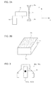
- FIG. 2A A positional relationship between the workpiece 6 placed on a workpiece placing table 9 and the wire electrode 5 stretched between upper and lower nozzles 8a and 8b is shown in Fig. 2A .
- the wire electrode 5 is not directly supported by the upper and lower nozzles 8a and 8b, but is supported by wire guides 10a and 10b which are embedded in the upper and lower nozzles 8a and 8b as shown in Fig. 3 .
- the workpiece 6 has an end surface (lateral surface) 6a, an upper plane surface 6b, and a lower plane surface 6c as shown in Fig. 2B .
- a method for detecting the upper plane surface 6b and the lower plane surface 6c of the workpiece 6 by using a wire-cut electric discharge machine including the contact state detection device 3 is described below.
- Fig. 4 illustrates that the upper wire guide 10a and the lower wire guide 10b which support the wire electrode 5 are preliminarily adjusted to be arranged in a vertical alignment before positions of the upper plane surface and the lower plane surface of the workpiece are detected.
- a height direction in a case where the position of the lower wire guide 10b is set as a reference is defined as Z-axis direction.
- a direction which is orthogonal to the Z axis and is a right-left direction of an elevation view of Fig. 4 is defined as X-axis direction.
- a direction which is orthogonal to both of the Z axis and the X axis is defined as Y-axis direction. That is, an X, Y, Z coordinate system of which the origin is the position of the lower wire guide 10b is set.
- movement in the horizontal direction of the wire-cut electric discharge machine is movement in the X-axis direction or in the Y-axis direction.
- movement in the horizontal direction of the wire-cut electric discharge machine is described below by using the movement in the X-axis direction.
- the upper wire guide 10a can actually be driven downward up to the level shown by a reference character Z 1 in Fig. 4 .
- the height of an upward driving limit in the Z-axis direction is defined as a position shown by a reference character Z 0 in Fig. 4 .
- a supporting portion (not shown) of the lower wire guide 10b does not have any movable portion and Z 0 constantly has a fixed value.
- Relative position and posture of the wire electrode 5 to the workpiece 6 can be changed by a combination of moving the workpiece placing table 9, on which the workpiece 6 is placed, in the X-axis direction and the Y-axis direction and moving the upper wire guide 10a in U-axis direction and V-axis direction.
- Fig. 5 illustrates that a position of the end surface 6a is detected by bringing the wire electrode 5 into contact with the workpiece 6.
- the end surface 6a of the workpiece 6 is first detected by bringing the wire electrode 5 into contact with the workpiece 6.
- the upper wire guide 10a and the lower wire guide 10b are brought closer to the workpiece 6 while keeping a state where those upper and lower wire guides 10a and 10b are arranged in a vertical alignment.
- positions of the upper and lower wire guides 10a and 10b at a time when the wire electrode 5 supported by those upper wire guide 10a and the lower wire guide 10b contacts with the workpiece 6 are detected and the detecting results are stored in a storage unit included in the numerical controller 2.
- contact between the wire electrode 5 and the workpiece 6 may be realized by bringing the wire electrode 5 closer to the workpiece 6 or by bringing the workpiece 6 closer to the wire electrode 5, depending on the mechanical configuration of the wire-cut electric discharge machine.
- the wire electrode 5 is moved backward in the X-axis direction from the position of the end surface 6a (a first position shown by a dashed line 100) by a fixed distance d 1 as shown in Fig. 6 .
- the X-axis direction positions of the upper and lower wire guides 10a and 10b which are moved backward are shown by a dashed line 110.
- the workpiece 6 may be moved with respect to the positions of the upper and lower wire guides 10a and 10b by the driving device or the upper and lower wire guides 10a and 10b may be moved with respect to the position of the workpiece 6, depending on the mechanical configuration of the wire-cut electric discharge machine.
- the upper wire guide 10a is moved in the X-axis direction toward the workpiece 6 until the wire electrode 5 contacts with the workpiece 6.
- the movement of the upper wire guide 10a is stopped.
- the stop position of the upper wire guide 10a is defined as a third position shown by a dashed line 120 of Fig. 7 .
- the position where the workpiece 6 and the wire electrode 5 contact with each other is set as a coordinate (1).
- the stop position (the third position) of the upper wire guide 10a is a position obtained when the upper wire guide 10a is moved in the X-axis direction by b 1 from the backward movement position in Fig. 6 .
- an angle A formed by the dashed line 100 and the wire electrode 5 can be obtained by the following formula (1).
- A tan - 1 b 1 a 1
- a 1 denotes a distance in the Z-axis direction from the lower wire guide 10b to the upper wire guide 10a.
- Z 2 in Fig. 7 is a Z coordinate value of the coordinate (1) and denotes a distance in the Z-axis direction from the lower wire guide 10b to an upper end portion of the end surface 6a of the workpiece 6 (in other words, from the lower wire guide 10b to the end portion of the upper plane surface 6b of the workpiece 6).
- This Z 2 can be obtained by the following formula (2) by using a backward movement amount d 1 of the upper and lower wire guides 10a and 10b from the end surface 6a of the workpiece 6 and the angle A of the wire electrode 5.
- Z 2 d 1 tan A
- the X-axis direction distance d 1 and the Z-axis direction distance Z 2 from the lower wire guide 10b which are shown in Fig. 7 , on a position (coordinate (1)) where the workpiece 6 contacts with the wire electrode 5 can be obtained.
- an X-axis direction distance d 2 and a Z-axis direction distance Z 3 from the lower wire guide 10b which are shown in Fig. 8 , on a position (coordinate (2)) where workpiece 6 contacts with the wire electrode 5 can be obtained in a similar manner.
- the "first position” shown by the dashed line 100, the "second position” shown by the dashed line 110, and the “third position” shown by the dashed line 120 in Fig. 7 are stored in a storage region in the numerical controller 2 which controls the wire-cut electric discharge machine.
- later-described positions shown by dashed lines 130, 140, 150, 200, 210, 220, 230, 240, 250, 300, 310, 320, 330, and 340 of Figs. 8, 10 to 14, 16, 18 , and 19 are also stored in the storage region in the numerical controller 2.
- the upper wire guide 10a is first moved backward in the X-axis direction to a position away at the fixed distance d 1 (a second position shown by the dashed line 110) from a position, which is an original position, of the end surface 6a of the workpiece 6 (the first position shown by the dashed line 100). A state after this movement is shown in Fig. 6 .
- the lower wire guide 10b is moved in the X-axis direction toward the workpiece 6 until the wire electrode 5 contacts with the workpiece 6, so as to detect a position (a third position shown by the dashed line 130) of the lower wire guide 10b at a time when the wire electrode 5 contacts with the workpiece 6.
- the X-axis direction distance and the Z-axis direction distance of the position (coordinate (2)) where the workpiece 6 contacts with the wire electrode 5 in this state, from the lower wire guide 10b, are d 2 and Z 3 .
- An angle B formed by the dashed line 130 representing the third position and the wire electrode 5 can be obtained by the following formula (3).
- B tan - 1 b 2 a 2
- b 2 and a 2 are respectively the X-axis distance and the Z-axis distance from the lower wire guide 10b to the upper wire guide 10a.
- Z 3 shown in Fig. 8 is a Z coordinate value of the coordinate (2), and denotes a distance in the Z-axis direction from the lower wire guide 10b to a lower end portion of the end surface 6a of the workpiece 6 (in other words, from the lower wire guide 10b to the end portion of the lower plane surface 6c of the workpiece 6).
- Z 3 d 2 tan B
- thickness to of the workpiece 6 can be obtained by the following formula (5).
- t 0 Z 2 - Z 3
- Fig. 10 illustrates that the upper wire guide 10a is moved in the X-axis direction toward the workpiece 6 until the wire electrode 5 contacts with the workpiece 6.
- the upper wire guide 10a is moved in the X-axis direction from a state where the upper and lower wire guides 10a and 10b are positioned away from the end surface 6a of the workpiece 6 at the distance of d 1 until the wire electrode 5 contacts with the workpiece 6.
- a position of the upper wire guide 10a at a time when the wire electrode 5 contacts with the workpiece 6 is shown by the dashed line 140.
- An angle C formed by the dashed line 110 representing the second position and the wire electrode 5 can be obtained by the following formula (6).
- C tan - 1 b 3 a 3
- b 3 and a 3 are an X-axis direction distance and a Z-axis direction distance from the upper wire guide 10a to the lower wire guide 10b.
- Z 4 shown in Fig. 10 is a distance in the Z-axis direction from the lower wire guide 10b to a portion, which contacts with the wire electrode 5, of the workpiece 6, and is a distance in the Z-axis direction from the lower wire guide 10b to an upper end portion of the end surface 6a of the workpiece 6 (in other words, from the lower wire guide 10b to the end portion of the upper plane surface 6b of the workpiece 6).
- This Z 4 can be obtained by the following formula (7) by using the backward movement amount d 1 of the upper and lower wire guides 10a and 10b from the end surface 6a of the workpiece 6 and the angle C of the wire electrode 5.
- Z 4 d 1 tan C
- Fig. 11 illustrates that the lower wire guide 10b is moved in the X-axis direction toward the workpiece 6 until the wire electrode 5 contacts with the workpiece 6.
- the dashed line 150 represents an X-axis direction position of the lower wire guide 10b which is moved.
- An angle D formed by the dashed line 150 and the wire electrode 5 can be obtained by the following formula (8).
- D tan - 1 b 4 a 4
- b 4 and a 4 are an X-axis direction distance and a Z-axis direction distance from the lower wire guide 10b to the upper wire guide 10a.
- Z 5 shown in Fig. 11 is a Z coordinate value of a portion, which contacts with the wire electrode 5, of the workpiece 6, and denotes a distance in the Z-axis direction from the lower wire guide 10b to a lower end portion of the end surface 6a of the workpiece 6 (in other words, from the lower wire guide 10b to the end portion of the lower plane surface 6c of the workpiece 6).
- Z 5 d 3 tan D
- the Z 4 (refer to Fig. 10 ) obtained by the above formula (7) can be considered as the Z-axis coordinate value of the upper plane surface 6b of the workpiece 6, so that an end of the nozzle 8a can be adjusted to the Z-axis coordinate value (level) by automatic adjustment, without manual operation.
- the thickness of the workpiece 6, that is, board thickness can be obtained, so that a machining condition can be automatically determined from the obtained board thickness.
- the machining condition is predetermined, whether the predetermined board thickness of the workpiece 6 is correct or not is determined. In a case where the predetermined board thickness of the workpiece 6 is incorrect, the machining condition can be reset so as to correspond to the obtained board thickness of the workpiece 6.
- the workpiece 6 is placed on the workpiece placing table 9 in such manner that the lower plane surface 6c is parallel with a placing surface of the workpiece placing table 9.
- the workpiece 6 is not horizontally placed due to some factors.
- Fig. 12 illustrates a case where the workpiece 6 is placed on the workpiece placing table 9 in an inclined manner.
- the board thickness of the workpiece 6 which is calculated by the above-mentioned method includes an error. If level adjustment of the upper and lower nozzles 8a and 8b is performed based on the board thickness of the workpiece 6 in which an error is included, those upper and lower nozzles 8a and 8b may hit the workpiece 6 and therefore the upper and lower nozzles 8a and 8b get damaged, or electric discharge machining is executed in a state where the upper and lower nozzles 8a and 8b are insufficiently close to the surface of the workpiece 6. Thus, above described problems occur.
- Fig. 13 illustrates a state where the wire electrode 5 contacts with the workpiece 6 with a certain inclination.
- a state where the workpiece 6 is inclined in a direction in which the upper end portion of the end surface 6a of the workpiece 6 moves away from the wire electrode 5 as shown in Fig. 12 is referred to below as an "inclination state 1".
- the wire electrode 5 is brought into contact with the workpiece 6 so as to detect a position of the end surface 6a of the workpiece 6 (an X-axis position shown by the dashed line 200) as is the case with Fig. 5 .
- the upper and lower wire guides 10a and 10b are simultaneously moved backward by the distance d 1 from the end surface 6a of the workpiece 6 (X-axis direction positions of the upper and lower wire guides l0a and 10b which are moved backward are shown by the dashed line 210) as is the case of Fig. 6 .
- the upper wire guide 10a is moved in the X-axis direction toward the workpiece 6 so as to bring the wire electrode 5 into contact with the workpiece 6.
- the dashed line 220 represents an X-axis direction position of this contacting position.
- Z 7 which is a Z coordinate value of a coordinate (3) is obtained by the following formula (12) by using a backward movement amount d 1 of the upper and lower wire guides 10a and 10b from the end surface 6a of the workpiece 6 and the angle E of the wire electrode 5.
- Z 7 d 1 tan E From this, it is understood that this Z 7 does not show a Z-axis direction position of the upper plane surface 6b of the workpiece 6 as shown in Fig. 13 .
- the upper and lower wire guides 10a and 10b are moved in the X-axis direction to backward positions from the end surface 6a of the workpiece 6 by a distance d 5 ( ⁇ d 1 ) (in other words, the upper and lower wire guides 10a and 10b are moved to positions on the dashed line 230 of Fig. 14 ). Then, the upper wire guide 10a is moved in the X-axis direction until the wire electrode 5 contacts with the workpiece 6 (moved to an X-axis direction position shown by the dashed line 240) as shown in Fig. 14 .
- Fig. 14 illustrates a case where the wire electrode 5 contacts with the workpiece 6 with an inclination which is different from that shown in Fig. 13 . It is sufficient that the distance d 5 shown in Fig. 14 is different from the distance d 1 shown in Fig. 13 , and the distance d 5 is not limited to the condition of d 5 ⁇ d 1 .
- An angle F shown in Fig. 14 is formed by the dashed line 200 and the wire electrode 5, and this angle F can be obtained by the following formula (13).
- F tan - 1 b 6 a 6
- Z 8 d 5 tan F
- Fig. 15 shows a state of the wire electrode 5 shown in Figs. 13 and 14 by using an X-Z coordinate system of which an origin is the P 1 .
- Fig. 15 shows a state of the wire electrode 5 shown in Figs. 13 and 14 by using an X-Z coordinate system of which an origin is the P 1 .
- a straight line L 1 represents a posture of the wire electrode 5 of Fig. 13 and a straight line L2 represents a posture of the wire electrode 5 of Fig. 14 .
- Z 7 is an intercept of the straight line L1 on the Z axis and Z 8 is an intercept of the straight line L2 on the Z axis.
- this intersection P 2 represents a position of the lower end portion of the end surface 6a of the workpiece 6 shown in Fig. 12 , at which the lower end portion contacts with the wire electrode in a case where the upper and lower wire guides 10a and 10b are on positions shown in Fig. 13 and also in another case where the upper and lower wire guides 10a and 10b are on positions shown in Fig. 14 .
- the upper and lower wire guides 10a and 10b are first returned to original positions shown by the dashed line 210.
- the original positions are not limited to the position which is away from the position of the dashed line 200, which represents the position of the end surface 6a of the workpiece 6, in the X-axis direction at the distance d 1 shown in Fig. 13 .
- the lower wire guide 10b is moved in the X-axis direction until the wire electrode 5 contacts with the workpiece 6.
- a position in the X-axis direction of the lower wire guide 10b at a time when the wire electrode 5 contacts with the workpiece 6 is shown by the dashed line 250.
- the lower wire guide 10b at this time is positioned forward from the position of the dashed line 200 by a distance d 7 .
- An angle G formed by the dashed line 250 and the wire electrode 5 can be obtained by the following formula (17).
- G tan - 1 b 7 a 7
- a 7 is a distance in the Z-axis direction from the lower wire guide 10b to the upper wire guide 10a.
- Z 9 which is a Z coordinate value of a coordinate (9) shown in Fig. 16 can be obtained by the following formula (18) by using the distance d 7 at this time and the angle G.
- Z 9 d 7 tan G
- Fig. 18 illustrates that after the wire electrode 5 is once brought into contact with the workpiece 6, the upper and lower wire guides 10a and 10b are moved backward by the distance d 1 .
- a state where the workpiece 6 is inclined in a direction in which the lower end portion of the end surface 6a of the workpiece 6 moves away from the wire electrode 5 as shown in Fig. 18 is referred to below as an "inclination state 2".
- the upper and lower wire guides 10a and 10b are moved backward by the distance d 1 (the X-axis direction positions of the upper and lower wire guides 10a and 10b which are moved backward are shown by the dashed line 310).
- the lower wire guide 10b is moved until the wire electrode 5 contacts with the workpiece 6.
- a position in the X-axis direction of the lower wire guide 10b at a time when the wire electrode 5 contacts with the workpiece 6 is shown by the dashed line 320.
- the lower wire guide 10b at this time is positioned forward from the position of the dashed line 300 by a distance d 8 .
- An angle H (refer to Fig. 19 ) formed by the dashed line 310 and the wire electrode 5 can be obtained by the following formula (20).
- H tan - 1 b 8 a 8
- a 8 denotes a distance in the Z-axis direction from the lower wire guide 10b to the upper wire guide 10a.
- Z 10 which is a Z coordinate value of a coordinate (5) shown in Fig. 19 can be obtained by the following formula (21) by using the distance d 8 at this time and the angle H.
- Z 10 d 8 tan H
- the upper and lower wire guides 10a and 10b are moved in the X-axis direction to backward positions from the end surface 6a of the workpiece 6 by the distance d 5 ( ⁇ d 1 ) (in other words, the upper and lower wire guides 10a and 10b are moved to positions on the dashed line 330 of Fig. 20 ).
- the lower wire guide 10b is moved in the X-axis direction until the wire electrode 5 contacts with the workpiece 6 as shown in Fig. 20 .
- the position in the X-axis direction of the lower wire guide 10b at a time when the wire electrode 5 contacts with the workpiece 6 is shown by the dashed line 340.
- the lower wire guide 10b at this time is positioned forward from the position of the dashed line 300 by the distance d 9 .
- An angle I formed by the dashed line 330 and the wire electrode 5 can be obtained by the following formula (22).
- d 1 is not equal to d 5 (d 1 ⁇ d 5 ), so that d 5 is not limited to be smaller than d 1 .
- I tan - 1 b 9 a 9
- a 9 is a distance in the Z-axis direction from the lower wire guide 10b to the upper wire guide 10a.
- Z 11 which is a Z coordinate value of a coordinate (6) shown in Fig. 20 can be obtained by the following formula (23) by using the distance d 9 at this time and the angle I.
- Z 11 d 9 tan I
- a case where the workpiece 6 is horizontally placed on the placing surface of the workpiece placing table 9 and the end surface 6a of the workpiece 6 is a vertical surface is considered.
- the dashed line 300 which is a vertical line passing the end surface 6a of the workpiece 6 is assumed to be the Z axis
- a horizontal direction line which is orthogonal to the Z axis and passes the lower wire guide 10b is assumed to be the X axis
- P 3 an intersection of the Z axis and the X axis
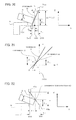
- Fig. 21 expresses a posture of the wire electrode 5, which is shown in Figs. 19 and 20 , in the form of a straight line by using an X-Z coordinate system of which the origin is P 3 .
- a straight line L3 represents the state of the wire electrode 5 of Fig. 19 and a straight line L4 represents the state of the wire electrode 5 of Fig. 20 .
- Z 10 is an intercept of the straight line L3 on the Z axis and Z 11 is an intercept of the straight line L4 on the Z axis.
- this intersection P 4 represents a position of the upper end portion of the end surface 6a of the workpiece 6 shown in Fig. 18 , at which the upper end portion contacts with the wire electrode in a case where the upper and lower wire guides 10a and 10b are on positions shown in Fig. 19 and also in a case where those upper and lower wire guides 10a and 10b are on other positions shown in Fig. 20 .
- the upper and lower wire guides 10a and 10b are returned to the original positions shown by the dashed line 300.
- the upper wire guide 10a is moved until the wire electrode 5 contacts with the workpiece 6.
- a position of the upper wire guide 10a in the X-axis direction at a time when the wire electrode 5 contacts with the workpiece 6 is shown by the dashed line 350.
- the upper wire guide 10a at this time is positioned forward from the original position of the dashed line 300 by a distance b 10 .
- An angle J formed by the dashed line 350 and the wire electrode 5 can be obtained by the following formula (26).
- J tan - 1 b 10 a 10
- a 10 denotes a distance in the Z-axis direction from the lower wire guide 10b to the upper wire guide 10a.
- Z 12 d 10 tan J
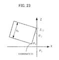
- a distance between the point Z 12 on the Z axis and the intersection P 4 (coordinate (7)) of the straight line L3 and the straight line L4 shown in Fig. 21 is calculated as board thickness t 3 of the workpiece 6, as shown in Fig. 23 .
- the workpiece 6 is inclined from the vertical direction by an angle ⁇ 2 .
- This inclination angle ⁇ 2 can be obtained by the following formula (28).
- ⁇ 2 tan - 1 ⁇ x 21 Z 12 - Z 21
- the upper and lower wire guides 10a and 10b can be moved so that the upper surface of the workpiece 6 and the wire electrode 5 become orthogonal to each other in accordance with the inclinations.
- the end surface 6a of the workpiece 6 which is inclined can be expressed by the following formula (29).
- Z - X tan ⁇ 2 + Z 12
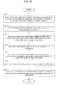
- Fig. 24 is a flowchart of algorithm for calculating positions of the upper and lower surfaces 6b and 6c of the workpiece 6 and board thicknesses in the wire-cut electric discharge machine according to the present invention.
- the wire electrode 5 keeps a vertical posture with respect to a surface, on which the workpiece 6 is placed, of the workpiece placing table 9, by a vertical adjustment function of the wire-cut electric discharge machine.
- the vertical adjustment function is a known technique (for example, refer to Japanese Patent Application Laid-Open No. 2003-71636 ).
- step SA07 calculations for obtaining an inclination angle of the wire electrode, a workpiece upper surface position, a workpiece lower surface position, and board thickness of the workpiece are performed by using the formulas (1) to (24).
- the end surface of the workpiece 6 is a vertical surface.
- the end surface of the workpiece 6 is not a complete vertical surface in reality and has some error.
- the workpiece 6 which is machined with the wire-cut electric discharge machine has thickness ranging from small thickness of approximately 5 mm to large thickness of 300 mm or more.
- the workpiece 6 having the thickness t 4 has an error of d 11 on its upper and lower surfaces as shown in Fig. 25 .
- the length of the inclined face of the workpiece is falsely recognized as the board thickness of the workpiece.
- the length of the inclined face is approximately 10.0005 mm.
- an error is 5 ⁇ m. Such small error can be ignored when machining conditions are set and adjustment of a nozzle gap is performed. Thus, there is no problem.
- the detection of the upper and lower surfaces of the workpiece which is performed by the wire-cut electric discharge machine of the present invention is applicable not only to machining from the end surface of the workpiece 6 but also machining which is started from a machined portion of the workpiece 6 as shown in Fig. 26 .
- an error of a distance between the upper plane surface 6b and the lower plane surface 6c (thickness of the workpiece) of the workpiece 6 is smaller than an error of the length of the end surface of the workpiece 6. Therefore, the error in this case is also ignorable.
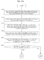
- Figs. 27A and 27B are flowcharts of detection of the upper and lower surfaces of the workpiece.
- the wire electrode 5 is vertically disposed with respect to the surface, on which the workpiece 6 is placed, of the workpiece placing table 9 with the vertical adjustment function of the wire-cut electric charge machine.
- the above-described vertical adjustment function is a known technique.
- Fig. 28 is a block diagram of a main part of the wire-cut electric discharge machine according to the embodiment of the present invention.
- a processor (CPU) 11 reads out a system program which is stored in a ROM 12 via a bus 20 and controls the whole of the numerical controller 2 in accordance with this system program.
- a RAM 13 stores temporary calculation data, display data, and the like.
- a SRAM 14 is configured as a nonvolatile memory of which a storage status is saved even if the numerical controller 2 is turned off.
- An interface 15 is an interface for external equipment and is connected with external equipment such as hard disk.
- a machining program is read from the external equipment and a machining program which is edited within the numerical controller 2 can be outputted to the external equipment.
- a programmable machine controller (PMC) 16 controls the wire-cut electric discharge machine by sequence programs installed in the numerical controller 2. That is, a command of the machining program is converted into a signal necessary for the wire-cut electric discharge machine by these sequence programs and the signal is outputted from an I/O unit 17 to the wire-cut electric discharge machine side.
- the contact state detection device 3 which detects contact between the wire electrode 5 and the workpiece 6 is connected to the I/O unit 17.
- a current position of each axis, an alarm, parameters, and an image signal of image data and the like are transmitted to a display device of a display device/MDI unit 70 and are displayed on the display device thereof.
- An interface 18 receives data from a keyboard of the display device/MDI unit 70 and transmits the data to the CPU 11.
- An interface 19 is connected with an electric discharge machining power source 71 and receives a speed command from the electric discharge machining power source 71.
- the electric discharge machining power source 71 monitors an electric discharging state of the wire electrode 5 and the workpiece 6 and informs the speed command including forward movement and backward movement to the CPU 11.
- Axis control circuits 30 to 33 receive movement commands of respective axes from the CPU 11 and output the commands of the respective axes to servo amplifiers 40 to 43. These servo amplifiers 40 to 43 receive the commands and drive servo motors 60 to 63 of the respective axes. In each of the servo motors 60 to 63 of respective axes of X, Y, U, and V, a speed detection device (not shown) for detecting a current speed is built in, and a feedback signal from the speed detection device is fed back to the corresponding axis control circuits 30 to 33.
- Servo control CPUs respectively built in the axis control circuits 30 to 33 execute respective processing of a position loop, a speed loop, and an electric current loop based on the feedback signals and the above-described movement commands and thus obtain torque commands for final driving control for respective axes so as to control positions and speeds of the servo motors 60 to 63 of the respective axes.
- the servo motors 60 and 61 of X and Y axes move the workpiece placing table 9, on which the workpiece 6 is placed, within a two-dimensional plane and the servo motors of U and V axes move the upper wire guide 10a.
Landscapes
- Engineering & Computer Science (AREA)
- Chemical & Material Sciences (AREA)
- Chemical Kinetics & Catalysis (AREA)
- Electrochemistry (AREA)
- Mechanical Engineering (AREA)
- Automation & Control Theory (AREA)
- Electrical Discharge Machining, Electrochemical Machining, And Combined Machining (AREA)
Abstract
Description
- The present invention relates to a wire-cut electric discharge machine which has a function of detecting upper and lower surfaces of a workpiece when machining the workpiece.
- A wire-cut electric discharge machine applies a voltage between poles of a wire electrode and a workpiece to generate electric discharge and at the same time, changes relative positions of the wire electrode to the workpiece, thus machining the workpiece in a desired form.
- Concerning a machining result of a workpiece, dimensional accuracy, verticality, and angle accuracy are commonly required. In order to obtain a desired machining result, it is necessary to accurately obtain relative positions of a wire electrode to a workpiece. These relative positions are accurately obtained on the basis of a relationship of relative vertical positions of the wire electrode to the workpiece. In order to solve the issue of securing the relationship of relative vertical positions, Japanese Patent Application Laid-Open No.
2003-71636 - In the technique disclosed in Japanese Patent Application Laid-Open No.
2003-71636 - Associated with storing the machining condition in the numerical controller, a gap interval between a nozzle for guiding machining fluid to a discharging part and a workpiece needs to be set. In prior art technique, adjustment of a gap between an end of a nozzle and a workpiece has been manually performed.
- In order to manually set a size of a gap between the end of the nozzle and the workpiece, such complicated operation is performed that an operator performs adjustment little by little by lowering a Z axis (vertical axis) in a running direction of a wire electrode little by little so that the gap has a designated fine value, while checking the gap with equipment such as a thickness gauge.
- A machining condition of a wire-cut electric discharge machine varies depending on the thickness of a workpiece, so that an operator usually recognizes the thickness of the workpiece. Therefore, in a case where a workpiece is directly mounted on a workpiece placing table, it can be considered that a nozzle level can be automatically adjusted to correspond to the thickness of the workpiece.
- Japanese Patent Application Laid-Open No.
7-299660 2005-111608 - In the wire-cut electric discharge machine, a workpiece is machined by electric discharge and at the same time, fine particles of the workpiece generated by the electric discharge are dispersed in machining fluid. If these fine particles float around the wire electrode, electric discharge is generated between the wire electrode and the fine particles. Accordingly, electric discharge between the wire electrode and the workpiece, which is required for machining a shape, is reduced, generating such problem that machining speed is reduced.
- In order to prevent the reduction of the machining speed due to such fine particles of the workpiece, it is necessary to remove fine particles around the wire electrode on a machining path so as to efficiently discharge to the workpiece, in the wire-cut electric discharge machine.
- Commonly, a diameter of a wire electrode is very small, for example, approximately a few hundred µm, and a width of a machining groove which is formed by electric discharge is approximately a little larger than the diameter of the wire electrode. In order to effectively remove fine particles from such thin machining groove, it is necessary to increase pressure of sprayed water, so that a gap between the nozzle end and the workpiece needs to be decreased.
- Even if an operator who performs machining of a workpiece with the wire-cut electric discharge machine recognizes the thickness of a workpiece, the thickness of the workpiece which is commonly used usually includes a dimensional error of approximately 100 µm to 200 µm. On the other hand, concerning adjustment of a gap between a nozzle end and a workpiece, it is sometimes required that the gap should be adjusted to be 100 µm to 200 µm depending on a machining condition. Therefore, it is impractical to automatically adjust a nozzle gap only depending on information of the thickness of a workpiece.
- In the technique disclosed in Japanese Patent Application Laid-Open No.
7-299660 - Further, in the technique disclosed in Japanese Patent Application Laid-Open No.
2005-111608 2005-111608 - An object of the present invention is to provide a wire-cut electric discharge machine having a function of accurately detecting a position of an upper surface or a lower surface of a workpiece or positions of the both surfaces of the workpiece by relatively moving upper and lower wire guides with respect to the workpiece and bringing a wire electrode into contact with the workpiece.
- A wire-cut electric discharge machine according to the present invention has a function of detecting an upper surface of a workpiece and includes a mechanism configured to relatively move a wire electrode that is stretched between upper and lower wire guides embedded in upper and lower nozzles with respect to a workpiece that is placed on a workpiece placing table. The wire-cut electric discharge machine comprises a contact detection unit configured to detect contact between the wire electrode and the workpiece, a movement control unit that relatively moves the wire electrode that is stretched between the upper and lower wire guides with respect to the workpiece after positioning the upper and lower wire guides so that the wire electrode becomes orthogonal to a horizontal surface, then stops the relative movement of the upper and lower wire guides with respect to the workpiece at a first position where contact between the wire electrode and the workpiece is detected, subsequently, relatively moves the upper and lower wire guides with respect to the workpiece, then stops the relative movement of the upper and lower wire guides with respect to the workpiece at a second position that is away from an end surface of the workpiece by a predetermined distance, subsequently, relatively moves the upper wire guide with respect to the workpiece in a state where the lower wire guide is not relatively moved, and then stops the relative movement of the upper wire guide with respect to the workpiece at a third position where the contact between the wire electrode and the workpiece is detected, a storage unit configured to store positions of the upper and lower wire guides obtained when the relative movement is stopped on the first position, the second position, and the third position, a wire electrode inclination angle calculating unit configured to calculate an inclination angle of the wire electrode lying at the third position from a relative distance in a horizontal direction of the upper wire guide obtained when the relative position of the upper wire guide with respect to the workpiece is changed from the second position to the third position and a distance in a vertical direction of the upper and lower wire guides, and a workpiece upper surface position calculating unit configured to calculate a distance from the lower wire guide to the upper surface of the workpiece based on the inclination angle of the wire electrode lying at the third position and a distance in a horizontal direction between the lower wire guide and the end surface of the workpiece lying at the third position.
- The movement control unit may relatively move the lower wire guide with respect to the workpiece in a state where the upper wire guide is not relatively moved after positioning the upper and lower wire guides on the second position, and stop the relative movement of the lower wire guide with respect to the workpiece at a fourth position where contact between the wire electrode and the workpiece is detected, the storage unit may store the position of the lower wire guide lying at the fourth position, and the wire electrode inclination angle calculating unit may calculate an inclination angle of the wire electrode lying at the fourth position from a relative distance in the horizontal direction obtained when the relative position of the lower wire guide with respect to the workpiece is changed from the second position to the fourth position and a distance in a vertical direction of the upper and lower wire guides. The wire-cut electric discharge machine may further comprises a workpiece lower surface position calculating unit configured to obtain a height from the lower wire guide to a lower surface of the workpiece based on an inclination angle of the wire electrode lying at the fourth position and a distance in a horizontal direction between the lower wire guide lying at the fourth position and the end surface of the workpiece, and a board thickness calculating unit configured to calculate board thickness of the workpiece from a height from the lower wire guide to the upper surface of the workpiece and a height from the lower wire guide to the lower surface of the workpiece.
- The wire-cut electric discharge machine may further comprise an upper nozzle positioning unit configured to position the upper nozzle so that a distance between the upper nozzle and the upper surface of the workpiece becomes a predetermined distance.
- According to the present invention, a wire-cut electric discharge machine that has a function of accurately detecting a position of an upper surface or a lower surface of a workpiece or positions of both of the upper and lower surfaces by relatively moving upper and lower wire guides and the workpiece and bringing a wire electrode into contact with the workpiece.
- Above-mentioned and other objects and features of the present invention will be apparent from the following embodiment described with reference to the accompanying drawings, in which
-
Fig. 1 is a schematic configuration diagram of a wire-cut electric discharge machine; -
Fig. 2A is a schematic configuration diagram of a wire electrode and a workpiece of a wire-cut electric discharge machine having a function of detecting a position of the wire electrode andFig. 2B is a schematic view of the workpiece; -
Fig. 3 illustrates a positional relationship between the wire electrode and the workpiece and illustrates that upper and lower nozzles in which wire guides are embedded; -
Fig. 4 illustrates that an upper wire guide and a lower wire guide which support the wire electrode are preliminarily adjusted to be placed in a vertical alignment before positions of an upper plane surface and a lower plane surface of the workpiece are detected; -
Fig. 5 illustrates that a position of an end surface of the workpiece is detected by bringing the wire electrode into contact with the workpiece; -
Fig. 6 illustrates that the wire electrode is moved backward by a predetermined distance from the position of the end surface of the workpiece after the position of the end surface of the workpiece is detected; -
Fig. 7 illustrates that the upper wire guide is moved toward the workpiece until the wire electrode contacts with the workpiece; -
Fig. 8 illustrates that the lower wire guide is moved toward the workpiece until the wire electrode contacts with the workpiece; -
Fig. 9 illustrates a case where the workpiece is fixed with a workpiece fixing jig; -
Fig. 10 illustrates that the upper wire guide is moved toward the workpiece until the wire electrode contacts with the workpiece; -
Fig. 11 illustrates that the lower wire guide is moved toward the workpiece until the wire electrode contacts with the workpiece; -
Fig. 12 illustrates a case where the workpiece is placed on a workpiece placing table in an inclined manner; -
Fig. 13 illustrates a case where the wire electrode having certain inclination contacts with the workpiece which is inclined; -
Fig. 14 illustrates a case where the wire electrode having inclination different from that ofFig. 13 contacts with the workpiece which is shown inFig. 13 ; -
Fig. 15 illustrates states of the wire electrode ofFigs. 13 and14 ; -
Fig. 16 illustrates a case where the wire electrode having certain inclination contacts with the workpiece which is inclined; -
Fig. 17 is an illustration for explaining formulas of inclination, board thickness, and an upper surface of the workpiece which is inclined; -
Fig. 18 illustrates that the wire electrode is moved backward by a distance d1 after the wire electrode is once brought into contact with an end of the workpiece; -
Fig. 19 illustrates a case where the wire electrode having certain inclination contacts with the workpiece which is inclined; -
Fig. 20 illustrates a case where the wire electrode having inclination different from that ofFig. 19 contacts with the workpiece which is shown inFig. 19 ; -
Fig. 21 illustrates states of the wire electrode ofFigs. 19 and20 ; -
Fig. 22 illustrates a state where the wire electrode is brought into contact with the workpiece which is in the states ofFig. 19 andFig. 20 ; -
Fig. 23 illustrates formulas of inclination, board thickness, and an upper surface of the workpiece which is inclined; -
Fig. 24 is a flowchart of algorithm for calculating positions of the upper and lower surfaces and board thicknesses of the workpiece in the wire-cut electric discharge machine according to the present invention; -
Fig. 25 illustrates a case where the end surface of the workpiece is inclined; -
Fig. 26 illustrates a case where machining is started from a machined part of the workpiece; -
Figs. 27A and27B are flowcharts of detection of the upper and lower surfaces of the workpiece; and -
Fig. 28 is a main part block diagram of the wire-cut electric discharge machine according to an embodiment of the present invention. -
Fig. 1 is a schematic configuration diagram showing a wire-cut electric discharge machine having a function of detecting a position of awire electrode 5 according to the present invention. - The wire-cut electric discharge machine shown in
Fig. 1 includes aservo driving device 1, anumerical controller 2, and a contactstate detection device 3. Theservo driving device 1 drivesservo motors numerical controller 2 so as to relatively move aworkpiece 6 which is placed on a workpiece placing table (not shown) with respect to thewire electrode 5. The contactstate detection device 3 detects contact of thewire electrode 5 and theworkpiece 6 by using contactstate detection pieces servo driving device 1, thenumerical controller 2, and the contactstate detection device 3 will be described later with reference toFig. 28 . - A positional relationship between the
workpiece 6 placed on a workpiece placing table 9 and thewire electrode 5 stretched between upper andlower nozzles Fig. 2A . Thewire electrode 5 is not directly supported by the upper andlower nozzles wire guides lower nozzles Fig. 3 . Here, theworkpiece 6 has an end surface (lateral surface) 6a, anupper plane surface 6b, and alower plane surface 6c as shown inFig. 2B . - A method for detecting the
upper plane surface 6b and thelower plane surface 6c of theworkpiece 6 by using a wire-cut electric discharge machine including the contactstate detection device 3 is described below. -
Fig. 4 illustrates that theupper wire guide 10a and thelower wire guide 10b which support thewire electrode 5 are preliminarily adjusted to be arranged in a vertical alignment before positions of the upper plane surface and the lower plane surface of the workpiece are detected. - The
workpiece 6 is placed on the workpiece placing table 9. Before the upper andlower plane surfaces workpiece 6 are detected, positions of the upper and lower wire guides 10a and 10b which support thewire electrode 5 are preliminarily adjusted so that thewire electrode 5 is stretched in a vertical direction. The end surface (lateral surface) 6a of theworkpiece 6 becomes parallel to thewire electrode 5. Here, a height direction in a case where the position of thelower wire guide 10b is set as a reference is defined as Z-axis direction. A direction which is orthogonal to the Z axis and is a right-left direction of an elevation view ofFig. 4 is defined as X-axis direction. A direction which is orthogonal to both of the Z axis and the X axis is defined as Y-axis direction. That is, an X, Y, Z coordinate system of which the origin is the position of thelower wire guide 10b is set. - Accordingly, movement in the horizontal direction of the wire-cut electric discharge machine is movement in the X-axis direction or in the Y-axis direction. However, the movement in the horizontal direction of the wire-cut electric discharge machine is described below by using the movement in the X-axis direction.
- Concerning the movement in the Z-axis direction (vertical direction) of the wire-cut electric discharge machine, the
upper wire guide 10a can actually be driven downward up to the level shown by a reference character Z1 inFig. 4 . Further, the height of an upward driving limit in the Z-axis direction is defined as a position shown by a reference character Z0 inFig. 4 . A supporting portion (not shown) of thelower wire guide 10b does not have any movable portion and Z0 constantly has a fixed value. - Relative position and posture of the
wire electrode 5 to theworkpiece 6 can be changed by a combination of moving the workpiece placing table 9, on which theworkpiece 6 is placed, in the X-axis direction and the Y-axis direction and moving theupper wire guide 10a in U-axis direction and V-axis direction. -
Fig. 5 illustrates that a position of theend surface 6a is detected by bringing thewire electrode 5 into contact with theworkpiece 6. - The
end surface 6a of theworkpiece 6 is first detected by bringing thewire electrode 5 into contact with theworkpiece 6. As shown inFig. 5 , theupper wire guide 10a and thelower wire guide 10b are brought closer to theworkpiece 6 while keeping a state where those upper and lower wire guides 10a and 10b are arranged in a vertical alignment. Then, positions of the upper and lower wire guides 10a and 10b at a time when thewire electrode 5 supported by thoseupper wire guide 10a and thelower wire guide 10b contacts with theworkpiece 6 are detected and the detecting results are stored in a storage unit included in thenumerical controller 2. Here, contact between thewire electrode 5 and theworkpiece 6 may be realized by bringing thewire electrode 5 closer to theworkpiece 6 or by bringing theworkpiece 6 closer to thewire electrode 5, depending on the mechanical configuration of the wire-cut electric discharge machine. - Next, after the contact of the
wire electrode 5 with respect to theend surface 6a of theworkpiece 6 is detected, thewire electrode 5 is moved backward in the X-axis direction from the position of theend surface 6a (a first position shown by a dashed line 100) by a fixed distance d1as shown inFig. 6 . The X-axis direction positions of the upper and lower wire guides 10a and 10b which are moved backward are shown by a dashedline 110. Concerning this backward movement up to the dashedline 110, theworkpiece 6 may be moved with respect to the positions of the upper and lower wire guides 10a and 10b by the driving device or the upper and lower wire guides 10a and 10b may be moved with respect to the position of theworkpiece 6, depending on the mechanical configuration of the wire-cut electric discharge machine. - Then, as shown in
Fig. 7 , theupper wire guide 10a is moved in the X-axis direction toward theworkpiece 6 until thewire electrode 5 contacts with theworkpiece 6. When thewire electrode 5 contacts with theworkpiece 6, the movement of theupper wire guide 10a is stopped. InFig. 7 , the stop position of theupper wire guide 10a is defined as a third position shown by a dashedline 120 ofFig. 7 . The position where theworkpiece 6 and thewire electrode 5 contact with each other is set as a coordinate (1). The stop position (the third position) of theupper wire guide 10a is a position obtained when theupper wire guide 10a is moved in the X-axis direction by b1 from the backward movement position inFig. 6 . InFig. 7 , an angle A formed by the dashedline 100 and thewire electrode 5 can be obtained by the following formula (1).
lower wire guide 10b to theupper wire guide 10a. - Z2 in
Fig. 7 is a Z coordinate value of the coordinate (1) and denotes a distance in the Z-axis direction from thelower wire guide 10b to an upper end portion of theend surface 6a of the workpiece 6 (in other words, from thelower wire guide 10b to the end portion of theupper plane surface 6b of the workpiece 6). This Z2 can be obtained by the following formula (2) by using a backward movement amount d1 of the upper and lower wire guides 10a and 10b from theend surface 6a of theworkpiece 6 and the angle A of thewire electrode 5.
- Here, in
Fig. 7 , a distance a1 and a distance d1 are set values, a distance b1 is a detected value, and d1/Z2=b1/a1, is satisfied, so that Z2 can be obtained by a calculation of Z2=a1xd1/b1. Accordingly, the X-axis direction distance d1 and the Z-axis direction distance Z2 from thelower wire guide 10b, which are shown inFig. 7 , on a position (coordinate (1)) where theworkpiece 6 contacts with thewire electrode 5 can be obtained. Here, an X-axis direction distance d2 and a Z-axis direction distance Z3 from thelower wire guide 10b, which are shown inFig. 8 , on a position (coordinate (2)) whereworkpiece 6 contacts with thewire electrode 5 can be obtained in a similar manner. - The "first position" shown by the dashed
line 100, the "second position" shown by the dashedline 110, and the "third position" shown by the dashedline 120 inFig. 7 are stored in a storage region in thenumerical controller 2 which controls the wire-cut electric discharge machine. In the same manner, later-described positions shown by dashedlines Figs. 8, 10 to 14, 16, 18 , and19 are also stored in the storage region in thenumerical controller 2. - A method for detecting the position of the
lower plane surface 6c of theworkpiece 6 is now described with reference toFigs. 6 and8 . - The
upper wire guide 10a is first moved backward in the X-axis direction to a position away at the fixed distance d1 (a second position shown by the dashed line 110) from a position, which is an original position, of theend surface 6a of the workpiece 6 (the first position shown by the dashed line 100). A state after this movement is shown inFig. 6 . - Then, as shown in
Fig. 8 , thelower wire guide 10b is moved in the X-axis direction toward theworkpiece 6 until thewire electrode 5 contacts with theworkpiece 6, so as to detect a position (a third position shown by the dashed line 130) of thelower wire guide 10b at a time when thewire electrode 5 contacts with theworkpiece 6. The X-axis direction distance and the Z-axis direction distance of the position (coordinate (2)) where theworkpiece 6 contacts with thewire electrode 5 in this state, from thelower wire guide 10b, are d2 and Z3. - An angle B formed by the dashed
line 130 representing the third position and thewire electrode 5 can be obtained by the following formula (3).
lower wire guide 10b to theupper wire guide 10a. - Z3 shown in
Fig. 8 is a Z coordinate value of the coordinate (2), and denotes a distance in the Z-axis direction from thelower wire guide 10b to a lower end portion of theend surface 6a of the workpiece 6 (in other words, from thelower wire guide 10b to the end portion of thelower plane surface 6c of the workpiece 6). This Z3 can be obtained by the following formula (4) by using d2 (=b2-d1) and the angle B of thewire electrode 5.
- Accordingly, thickness to of the
workpiece 6 can be obtained by the following formula (5).
- The above description shows an example of directly fixing the
workpiece 6 on the workpiece placing table 9. Next, an example that theworkpiece 6 is fixed on the workpiece placing table 9 by means of aworkpiece fixing jig 90 is described with reference toFigs. 9 to 11 . InFig. 9 , the positional relationship between thewire electrode 5 and theend surface 6a of theworkpiece 6 is the same as that of the case ofFig. 4 . -
Fig. 10 illustrates that theupper wire guide 10a is moved in the X-axis direction toward theworkpiece 6 until thewire electrode 5 contacts with theworkpiece 6. - The
upper wire guide 10a is moved in the X-axis direction from a state where the upper and lower wire guides 10a and 10b are positioned away from theend surface 6a of theworkpiece 6 at the distance of d1 until thewire electrode 5 contacts with theworkpiece 6. A position of theupper wire guide 10a at a time when thewire electrode 5 contacts with theworkpiece 6 is shown by the dashedline 140. An angle C formed by the dashedline 110 representing the second position and thewire electrode 5 can be obtained by the following formula (6).
upper wire guide 10a to thelower wire guide 10b. - Z4 shown in
Fig. 10 is a distance in the Z-axis direction from thelower wire guide 10b to a portion, which contacts with thewire electrode 5, of theworkpiece 6, and is a distance in the Z-axis direction from thelower wire guide 10b to an upper end portion of theend surface 6a of the workpiece 6 (in other words, from thelower wire guide 10b to the end portion of theupper plane surface 6b of the workpiece 6). This Z4 can be obtained by the following formula (7) by using the backward movement amount d1 of the upper and lower wire guides 10a and 10b from theend surface 6a of theworkpiece 6 and the angle C of thewire electrode 5.
- Next, only the
upper wire guide 10a is moved so as to be returned to the original position (the second position shown by the dashed line 110). The returned positional relationship between thewire electrode 5 and theend surface 6a of theworkpiece 6 is the same as that inFig. 6 . -
Fig. 11 illustrates that thelower wire guide 10b is moved in the X-axis direction toward theworkpiece 6 until thewire electrode 5 contacts with theworkpiece 6. The dashedline 150 represents an X-axis direction position of thelower wire guide 10b which is moved. An angle D formed by the dashedline 150 and thewire electrode 5 can be obtained by the following formula (8).
lower wire guide 10b to theupper wire guide 10a. - Z5 shown in
Fig. 11 is a Z coordinate value of a portion, which contacts with thewire electrode 5, of theworkpiece 6, and denotes a distance in the Z-axis direction from thelower wire guide 10b to a lower end portion of theend surface 6a of the workpiece 6 (in other words, from thelower wire guide 10b to the end portion of thelower plane surface 6c of the workpiece 6). This Z5 can be obtained by the following formula (9) by using the distance d3 (=b4-d1) and the angle D of thewire electrode 5.
- The Z5 can be considered as the Z-axis coordinate value of the
lower plane surface 6c of theworkpiece 6. Accordingly, thickness t1 of theworkpiece 6 can be obtained by the following formula (10).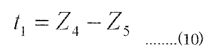
- The Z4 (refer to
Fig. 10 ) obtained by the above formula (7) can be considered as the Z-axis coordinate value of theupper plane surface 6b of theworkpiece 6, so that an end of thenozzle 8a can be adjusted to the Z-axis coordinate value (level) by automatic adjustment, without manual operation. Further, the thickness of theworkpiece 6, that is, board thickness can be obtained, so that a machining condition can be automatically determined from the obtained board thickness. When the machining condition is predetermined, whether the predetermined board thickness of theworkpiece 6 is correct or not is determined. In a case where the predetermined board thickness of theworkpiece 6 is incorrect, the machining condition can be reset so as to correspond to the obtained board thickness of theworkpiece 6. - It is ideal that the
workpiece 6 is placed on the workpiece placing table 9 in such manner that thelower plane surface 6c is parallel with a placing surface of the workpiece placing table 9. However, there are some cases where theworkpiece 6 is not horizontally placed due to some factors. -
Fig. 12 illustrates a case where theworkpiece 6 is placed on the workpiece placing table 9 in an inclined manner. - In a case where the
workpiece 6 is not horizontally placed on the workpiece placing table 9 as the state shown inFig. 12 andFig. 18 which is described later, the board thickness of theworkpiece 6 which is calculated by the above-mentioned method includes an error. If level adjustment of the upper andlower nozzles workpiece 6 in which an error is included, those upper andlower nozzles workpiece 6 and therefore the upper andlower nozzles lower nozzles workpiece 6. Thus, above described problems occur. - Here, an automatic adjustment method of the upper and
lower nozzles workpiece 6 is not horizontally placed on the placing surface of the workpiece placing table 9 is described with reference toFigs. 12 and 13. Fig. 13 illustrates a state where thewire electrode 5 contacts with theworkpiece 6 with a certain inclination. - A state where the
workpiece 6 is inclined in a direction in which the upper end portion of theend surface 6a of theworkpiece 6 moves away from thewire electrode 5 as shown inFig. 12 is referred to below as an "inclination state 1". - As shown in
Fig. 12 , thewire electrode 5 is brought into contact with theworkpiece 6 so as to detect a position of theend surface 6a of the workpiece 6 (an X-axis position shown by the dashed line 200) as is the case withFig. 5 . Then, the upper and lower wire guides 10a and 10b are simultaneously moved backward by the distance d1 from theend surface 6a of the workpiece 6 (X-axis direction positions of the upper and lower wire guides l0a and 10b which are moved backward are shown by the dashed line 210) as is the case ofFig. 6 . - Subsequently, as shown in
Fig. 13 , theupper wire guide 10a is moved in the X-axis direction toward theworkpiece 6 so as to bring thewire electrode 5 into contact with theworkpiece 6. The dashedline 220 represents an X-axis direction position of this contacting position. An angle E formed by the dashedline 200 and thewire electrode 5 can be obtained by the following formula (11).
- Here, as in the case where Z2 shown in
Fig. 7 is obtained by the above formula (2), Z7 which is a Z coordinate value of a coordinate (3) is obtained by the following formula (12) by using a backward movement amount d1 of the upper and lower wire guides 10a and 10b from theend surface 6a of theworkpiece 6 and the angle E of thewire electrode 5.
upper plane surface 6b of theworkpiece 6 as shown inFig. 13 . - Subsequent to the state of
Fig. 13 , the upper and lower wire guides 10a and 10b are moved in the X-axis direction to backward positions from theend surface 6a of theworkpiece 6 by a distance d5 (<d1) (in other words, the upper and lower wire guides 10a and 10b are moved to positions on the dashedline 230 ofFig. 14 ). Then, theupper wire guide 10a is moved in the X-axis direction until thewire electrode 5 contacts with the workpiece 6 (moved to an X-axis direction position shown by the dashed line 240) as shown inFig. 14 . -
Fig. 14 illustrates a case where thewire electrode 5 contacts with theworkpiece 6 with an inclination which is different from that shown inFig. 13 . It is sufficient that the distance d5 shown inFig. 14 is different from the distance d1 shown inFig. 13 , and the distance d5 is not limited to the condition of d5<d1. An angle F shown inFig. 14 is formed by the dashedline 200 and thewire electrode 5, and this angle F can be obtained by the following formula (13).
- Here, Z8 which is a Z coordinate value of a coordinate (4) can be obtained by the following formula (14) by using the distance d5 (=(b6-d5)) and the
angle F. 
- Though this Z8 does not correctly show a position in the Z-axis direction of the
upper plane surface 6b of theworkpiece 6, it has already shown that a relationship of Z7>Z8 is satisfied when the upper and lower wire guides 10a and 10b are moved and measured, as described above. Accordingly, it is understood that theworkpiece 6 is inclined with respect to the workpiece placing table 9 as shown inFig. 12 (inclination state 1). In this specification, the description has been given on the premise that theworkpiece 6 is inclined as shown inFig. 12 thus far. However, in actual machining, it is hard to determine whether theworkpiece 6 is inclined. If Z7 is equal to Z8 (Z7=Z8), it can be considered that theend surface 6a of theworkpiece 6 is vertical or inclined asFig. 18 described later. Here, theend surface 6a of theworkpiece 6 is set to be orthogonal to both of theupper plane surface 6b and thelower plane surface 6c. - Here, such a case is considered that the
workpiece 6 is horizontally placed on the placing surface of the workpiece placing table 9 and theend surface 6a of theworkpiece 6 is a vertical surface. The dashedline 200 which is a vertical line passing theend surface 6a of theworkpiece 6 is set as the Z axis, a horizontal line which is orthogonal to the Z axis and passes thelower wire guide 10b is set as the X axis, and an intersection of the Z axis and the X axis is denoted as P1.Fig. 15 shows a state of thewire electrode 5 shown inFigs. 13 and14 by using an X-Z coordinate system of which an origin is the P1. InFig. 15 , a straight line L1 represents a posture of thewire electrode 5 ofFig. 13 and a straight line L2 represents a posture of thewire electrode 5 ofFig. 14 . Here, Z7 is an intercept of the straight line L1 on the Z axis and Z8 is an intercept of the straight line L2 on the Z axis. - The straight lines L1 and L2 on the X-Z coordinate system of which the origin is P1 can be expressed as the following formulas (15) and (16).


- Further, in the X-Z coordinate system of which the origin is P1 shown in
Fig. 15 , an intersection of the straight line L1 and the straight line L2 is denoted as P2 (coordinate (8)), and an X coordinate value and a Z coordinate value of the intersection P2 are respectively denoted as X20 and Z20. That is, this intersection P2 represents a position of the lower end portion of theend surface 6a of theworkpiece 6 shown inFig. 12 , at which the lower end portion contacts with the wire electrode in a case where the upper and lower wire guides 10a and 10b are on positions shown inFig. 13 and also in another case where the upper and lower wire guides 10a and 10b are on positions shown inFig. 14 . - Next, a method for obtaining a position of the
lower plane surface 6c of theworkpiece 6 is described with reference toFig. 16 . - The upper and lower wire guides 10a and 10b are first returned to original positions shown by the dashed
line 210. Here, the original positions are not limited to the position which is away from the position of the dashedline 200, which represents the position of theend surface 6a of theworkpiece 6, in the X-axis direction at the distance d1 shown inFig. 13 . - Then, as shown in
Fig. 16 , thelower wire guide 10b is moved in the X-axis direction until thewire electrode 5 contacts with theworkpiece 6. A position in the X-axis direction of thelower wire guide 10b at a time when thewire electrode 5 contacts with theworkpiece 6 is shown by the dashedline 250. Thelower wire guide 10b at this time is positioned forward from the position of the dashedline 200 by a distance d7. An angle G formed by the dashedline 250 and thewire electrode 5 can be obtained by the following formula (17).
lower wire guide 10b to theupper wire guide 10a. - Z9 which is a Z coordinate value of a coordinate (9) shown in
Fig. 16 can be obtained by the following formula (18) by using the distance d7 at this time and theangle G. 
- The automatic adjustment method of the upper and
lower nozzles workpiece 6 is not horizontally placed on the placing surface of the workpiece placing table 9 has been described thus far with reference toFigs. 12 and 13 . However, in actual machining, it is hard to preliminarily determine fine inclination of the workpiece. - Therefore, after the measurement performed in
Fig. 16 by moving the upper and lower wire guides 10a and 10b backward from theend surface 6a of theworkpiece 6 by the backward movement amount d1, measurement by moving the upper and lower wire guides 10a and 10b backward from theend surface 6a of theworkpiece 6 by a backward movement amount d5 (#d1) is performed as in the case of the measurement performed inFigs. 14 and 15 . The resulting level of thelower plane surface 6c of theworkpiece 6 is denoted as Z9'. In a case where theworkpiece 6 is inclined as shown inFig. 12 , Z9 becomes equal to Z9' (Z9=Z9' ). - Here, it can be determined that the
workpiece 6 is in the "inclination state 1" from the relationship of Z7#Z8 and Z9=Z9'. - Based on the above-mentioned result, in the X-Z coordinate of which the origin is P1, a distance between the point Z9 on the Z axis and the intersection P2 (coordinate (8)) of the straight line L1 and the straight line L2 shown in
Fig. 15 is calculated as board thickness t2 of theworkpiece 6, as shown inFig. 17 . At the same time, it is understood that theworkpiece 6 is inclined from the vertical direction by an angle θ1. This inclination angle θ1 can be obtained by the following formula (19).
- A case where the inclination of the
workpiece 6 is theinclination state 2 is now described. -
Fig. 18 illustrates that after thewire electrode 5 is once brought into contact with theworkpiece 6, the upper and lower wire guides 10a and 10b are moved backward by the distance d1. - A state where the
workpiece 6 is inclined in a direction in which the lower end portion of theend surface 6a of theworkpiece 6 moves away from thewire electrode 5 as shown inFig. 18 is referred to below as an "inclination state 2". - As shown in
Fig. 18 , after thewire electrode 5 is once brought into contact with theworkpiece 6 and the contact position (an X-axis direction position shown by the dashed line 300) is detected, the upper and lower wire guides 10a and 10b are moved backward by the distance d1 (the X-axis direction positions of the upper and lower wire guides 10a and 10b which are moved backward are shown by the dashed line 310). Subsequently, as shown inFig. 19 , thelower wire guide 10b is moved until thewire electrode 5 contacts with theworkpiece 6. A position in the X-axis direction of thelower wire guide 10b at a time when thewire electrode 5 contacts with theworkpiece 6 is shown by the dashedline 320. Thelower wire guide 10b at this time is positioned forward from the position of the dashedline 300 by a distance d8. An angle H (refer toFig. 19 ) formed by the dashedline 310 and thewire electrode 5 can be obtained by the following formula (20).
- In the above formula, b8 is sum of d8 and d1 (b8=d8+d1). a8 denotes a distance in the Z-axis direction from the
lower wire guide 10b to theupper wire guide 10a. - Z10 which is a Z coordinate value of a coordinate (5) shown in
Fig. 19 can be obtained by the following formula (21) by using the distance d8 at this time and the angle H.
- Subsequent to the state of
Fig. 19 , the upper and lower wire guides 10a and 10b are moved in the X-axis direction to backward positions from theend surface 6a of theworkpiece 6 by the distance d5 (<d1) (in other words, the upper and lower wire guides 10a and 10b are moved to positions on the dashedline 330 ofFig. 20 ). Then, thelower wire guide 10b is moved in the X-axis direction until thewire electrode 5 contacts with theworkpiece 6 as shown inFig. 20 . The position in the X-axis direction of thelower wire guide 10b at a time when thewire electrode 5 contacts with theworkpiece 6 is shown by the dashedline 340. Thelower wire guide 10b at this time is positioned forward from the position of the dashedline 300 by the distance d9. An angle I formed by the dashedline 330 and thewire electrode 5 can be obtained by the following formula (22). Here, it is sufficient that d1 is not equal to d5 (d1≠d5), so that d5 is not limited to be smaller than d1.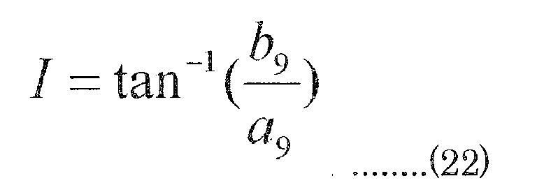
lower wire guide 10b to theupper wire guide 10a. - Z11 which is a Z coordinate value of a coordinate (6) shown in
Fig. 20 can be obtained by the following formula (23) by using the distance d9 at this time and the angle I.
- These Z10 and Z11 do not correctly show the position in the Z-axis direction of the
lower plane surface 6c of theworkpiece 6. - Here, a case where the
workpiece 6 is horizontally placed on the placing surface of the workpiece placing table 9 and theend surface 6a of theworkpiece 6 is a vertical surface is considered. The dashedline 300 which is a vertical line passing theend surface 6a of theworkpiece 6 is assumed to be the Z axis, a horizontal direction line which is orthogonal to the Z axis and passes thelower wire guide 10b is assumed to be the X axis, and an intersection of the Z axis and the X axis is denoted as P3.Fig. 21 expresses a posture of thewire electrode 5, which is shown inFigs. 19 and20 , in the form of a straight line by using an X-Z coordinate system of which the origin is P3. InFig. 21 , a straight line L3 represents the state of thewire electrode 5 ofFig. 19 and a straight line L4 represents the state of thewire electrode 5 ofFig. 20 . Here, Z10 is an intercept of the straight line L3 on the Z axis and Z11 is an intercept of the straight line L4 on the Z axis. - The straight lines L3 and L4 on the X-Z coordinate system of which the origin is P3 can be expressed as the following formulas (24) and (25).


- Further, in the X-Z coordinate system of which the origin is P3 shown in
Fig. 21 , an intersection of the straight line L3 and the straight line L4 is denoted as P4 (coordinate (7)), and an X coordinate value and a Z coordinate value of the intersection P4 are respectively denoted as X21 and Z21. That is, this intersection P4 represents a position of the upper end portion of theend surface 6a of theworkpiece 6 shown inFig. 18 , at which the upper end portion contacts with the wire electrode in a case where the upper and lower wire guides 10a and 10b are on positions shown inFig. 19 and also in a case where those upper and lower wire guides 10a and 10b are on other positions shown inFig. 20 . - The upper and lower wire guides 10a and 10b are returned to the original positions shown by the dashed
line 300. - Subsequently, as shown in
Fig. 22 , theupper wire guide 10a is moved until thewire electrode 5 contacts with theworkpiece 6. A position of theupper wire guide 10a in the X-axis direction at a time when thewire electrode 5 contacts with theworkpiece 6 is shown by the dashedline 350. Theupper wire guide 10a at this time is positioned forward from the original position of the dashedline 300 by a distance b10. An angle J formed by the dashedline 350 and thewire electrode 5 can be obtained by the following formula (26).
lower wire guide 10b to theupper wire guide 10a. - Z12 which is the Z coordinate value of the coordinate (3) (= coordinate (4)) can be obtained by the following formula (27) by using the distance d10 at this time and the angle J. Here, in the state where the coordinate (3) becomes equal to the coordinate (4) in
Fig. 22 , measurement of an edge of theupper plane surface 6b of theworkpiece 6 can be performed as shown inFigs. 13 and14 .
- Here, in the X-Z coordinate of which the origin is P3, a distance between the point Z12 on the Z axis and the intersection P4 (coordinate (7)) of the straight line L3 and the straight line L4 shown in
Fig. 21 is calculated as board thickness t3 of theworkpiece 6, as shown inFig. 23 . At the same time, it is understood that theworkpiece 6 is inclined from the vertical direction by an angle θ2. This inclination angle θ2 can be obtained by the following formula (28).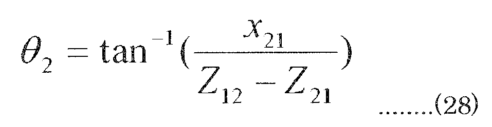
- If the inclinations θ1 and θ2 of the
workpiece 6 can be obtained, the upper and lower wire guides 10a and 10b can be moved so that the upper surface of theworkpiece 6 and thewire electrode 5 become orthogonal to each other in accordance with the inclinations. - The
end surface 6a of theworkpiece 6 which is inclined can be expressed by the following formula (29).
- Here, although it is not clear to what extent the
workpiece 6 actually extends in the X-axis negative direction, if it is assumed that theworkpiece 6 extends from the measurement point where X coordinate is zero, as shown inFig. 23 , to the point which corresponds to a drive limit of the wire-cut electric discharge machine, then it would be possible to estimate the level of the assumedworkpiece 6. - By positioning the end of the
upper nozzle 8a in accordance with an above-obtained higher position of the upper surface of theworkpiece 6 which is inclined, contact of theworkpiece 6 and the end of theupper nozzle 8a can be prevented. Further, a straight line expressing theupper plane surface 6a of theworkpiece 6 which is placed to in an inclined manner as shown inFig. 17 can be obtained by the following formula (30), as is the case withFig. 23 .
- Concerning the above formula (30) as well, if it is assumed that the
workpiece 6 extends from the measurement point where X coordinate is zero, as shown inFig. 23 , to the point which corresponds to a drive limit of the wire-cut electric discharge machine, then it would be possible to estimate the level of the assumedworkpiece 6, as a result, contact of theworkpiece 6 and the end of theupper nozzle 8a can be prevented. -
Fig. 24 is a flowchart of algorithm for calculating positions of the upper andlower surfaces workpiece 6 and board thicknesses in the wire-cut electric discharge machine according to the present invention. Here, it is assumed that thewire electrode 5 keeps a vertical posture with respect to a surface, on which theworkpiece 6 is placed, of the workpiece placing table 9, by a vertical adjustment function of the wire-cut electric discharge machine. The vertical adjustment function is a known technique (for example, refer to Japanese Patent Application Laid-Open No.2003-71636 - The processing executed at respective steps is described below.
- [Step SA01] The upper and lower wire guides are moved and thus the wire electrode is brought into contact with the workpiece so as to detect and store positions of the upper and lower wire guides at a time when the wire electrode contacts with the workpiece.
- [Step SA02] When the wire electrode contacts with the workpiece, the upper and lower wire guides are moved from the positions to position (position A) backward by a fixed distance (d1).
- [Step SA03] Only the upper wire guide is moved and the wire electrode is brought into contact with the workpiece so as to detect and store a position of the upper wire guide at a time of the contact.
- [Step SA04] Only the upper wire guide is moved so as to return the upper wire guide to the position A.
- [Step SA05] Only the lower wire guide is moved and thus the wire electrode is brought into contact with the workpiece so as to detect and store a position of the lower wire guide at a time of the contact.
- [Step SA06] Only the lower wire guide is moved so as to return the lower wire guide to the position A.
- [Step SA07] A coordinate value of the position where the wire electrode contacts with the workpiece is calculated and the board thickness of the workpiece is calculated from the calculated coordinate value. Then, this processing is ended.
- As supplement description of the above-described flowchart, a "wire electrode inclination angle calculating unit", a "workpiece upper surface position calculating unit", a "workpiece lower surface calculating unit", and a "board thickness calculating unit", which constitutes the wire-cut electric discharge machine according to the present invention, perform the function of step SA07 described above. In this step SA07, calculations for obtaining an inclination angle of the wire electrode, a workpiece upper surface position, a workpiece lower surface position, and board thickness of the workpiece are performed by using the formulas (1) to (24).
- In the above description, it is described that the end surface of the
workpiece 6 is a vertical surface. The end surface of theworkpiece 6 is not a complete vertical surface in reality and has some error. Commonly, theworkpiece 6 which is machined with the wire-cut electric discharge machine has thickness ranging from small thickness of approximately 5 mm to large thickness of 300 mm or more. - Here, it is assumed that the
workpiece 6 having the thickness t4 has an error of d11 on its upper and lower surfaces as shown inFig. 25 . In this case, the length of an inclined face (end surface) of the workpiece can be obtained by the following formula (31).
- In the above-described method for detecting the upper and lower surfaces of the workpiece, the length of the inclined face of the workpiece is falsely recognized as the board thickness of the workpiece. Here, if calculation is performed under conditions of t4=10 mm and d11=0.3 mm, the length of the inclined face is approximately 10.0005 mm. Thus, an error is 5 µm. Such small error can be ignored when machining conditions are set and adjustment of a nozzle gap is performed. Thus, there is no problem.
- As another example, if calculation is performed under conditions of t4=50 mm and d11=0.3 mm, the length of the inclined face is approximately 50.001 mm. Thus, an error is 1 µm, and such small error does not cause any problem as well.
- The detection of the upper and lower surfaces of the workpiece which is performed by the wire-cut electric discharge machine of the present invention is applicable not only to machining from the end surface of the
workpiece 6 but also machining which is started from a machined portion of theworkpiece 6 as shown inFig. 26 . In this case, an error of a distance between theupper plane surface 6b and thelower plane surface 6c (thickness of the workpiece) of theworkpiece 6 is smaller than an error of the length of the end surface of theworkpiece 6. Therefore, the error in this case is also ignorable. - Accordingly, in the method for detecting the upper and lower surfaces of the workpiece with the wire-cut electric discharge machine of the present invention in a case where the
workpiece 6 is inclined as shown inFigs. 12 and18 , an extent of contribution of an inclination error of the end surface of a real workpiece is negligible small. -
Figs. 27A and27B are flowcharts of detection of the upper and lower surfaces of the workpiece. Here, it is assumed that thewire electrode 5 is vertically disposed with respect to the surface, on which theworkpiece 6 is placed, of the workpiece placing table 9 with the vertical adjustment function of the wire-cut electric charge machine. The above-described vertical adjustment function is a known technique. - The processing executed at respective steps is described below.
- [Step SB01] The upper and lower wire guides are moved and thus the wire electrode is brought into contact with the workpiece so as to detect and store positions of the upper and lower wire guides at a time when the wire electrode contacts with the workpiece.
- [Step SB02] After the wire electrode contacts with the workpiece, the upper and lower wire guides are moved to positions (position A) backward by a fixed distance (d1).
- [Step SB03] Only the upper wire guide is moved, the wire electrode is brought into contact with the workpiece, and thereby a position of the upper wire guide at a time when the wire electrode contact with the workpiece is detected and stored so as to calculate a value of the coordinate (3) of the workpiece with which the wire electrode contacts.
- [Step SB04] The lower wire guide is moved to the position B which is away from the end surface by the distance d5.
- [Step SB05] Only the upper wire guide is moved, the wire electrode is brought into contact with the workpiece, and thereby a position of the upper wire guide at a time when the wire electrode contacts with the workpiece is detected and stored so as to calculate a value of the coordinate (4) on the position of the workpiece with which the wire electrode contacts.
- [Step SB06] Whether or not the value of the coordinate (3) and the value of the coordinate (4) are the same as each other is determined. When the values are the same as each other, the processing proceeds to step SB07. When the values are not same as each other, the processing proceeds to step SB15.
- [Step SB07] The upper and lower wire guides are moved to the position A.
- [Step SB08] Only the lower wire guide is moved, the wire electrode is brought into contact with the workpiece, and thereby a position of the lower wire guide at a time when the wire electrode contacts with the workpiece is detected so as to calculate a value of the coordinate (5) on the position of the workpiece with which the wire electrode contacts.
- [Step SB09] The upper wire guide is moved to the position B which is away from the end surface of the workpiece by the distance d5.
- [Step SB10] Only the lower wire guide is moved, the wire electrode is brought into contact with the workpiece, and thereby a position of the lower wire guide at a time when the wire electrode contacts with the workpiece is detected so as to calculate a value of the coordinate (6) on the position of the workpiece with which the wire electrode contacts.
- [Step SB11] Whether the value of the coordinate (5) and the value of the coordinate (6) are same as each other is determined. When the values are same as each other, the processing proceeds to step SB12. When the values are not same as each other, the processing proceeds to step SB13.
- [Step SB12] It is determined that the workpiece is horizontally placed from the coordinate (3) = the coordinate (4) and the coordinate (5) = the coordinate (6), and the board thickness is calculated (there is no inclination of the workpiece).
- [Step SB13] A position of the wire electrode on the position of the coordinate (5) and a position of the wire electrode on the position of the coordinate (6) are respectively expressed as formulas, and a value of the coordinate (7) of the intersection is obtained.
- [Step SB14] Board thickness and an inclination angle of the workpiece are calculated.
- [Step SB15] A position of the wire electrode on the position of the coordinate (3) and a position of the wire electrode on the position of the coordinate (4) are respectively expressed as formulas, and a value of the coordinate (8) of the intersection is obtained.
- [Step Sub16] The upper and lower wire guides are moved to the position A.
- [Step SB17] Only the lower wire guide is moved and thus the wire electrode is brought into contact with the workpiece so as to calculate the value of the coordinate (9) at this time.
- [Step SB18] Board thickness and an inclination angle of the workpiece are calculated and then this processing is ended.
-
Fig. 28 is a block diagram of a main part of the wire-cut electric discharge machine according to the embodiment of the present invention. - A processor (CPU) 11 reads out a system program which is stored in a
ROM 12 via abus 20 and controls the whole of thenumerical controller 2 in accordance with this system program. ARAM 13 stores temporary calculation data, display data, and the like. ASRAM 14 is configured as a nonvolatile memory of which a storage status is saved even if thenumerical controller 2 is turned off. - An
interface 15 is an interface for external equipment and is connected with external equipment such as hard disk. A machining program is read from the external equipment and a machining program which is edited within thenumerical controller 2 can be outputted to the external equipment. - A programmable machine controller (PMC) 16 controls the wire-cut electric discharge machine by sequence programs installed in the
numerical controller 2. That is, a command of the machining program is converted into a signal necessary for the wire-cut electric discharge machine by these sequence programs and the signal is outputted from an I/O unit 17 to the wire-cut electric discharge machine side. Especially, in association with the present invention, the contactstate detection device 3 which detects contact between thewire electrode 5 and theworkpiece 6 is connected to the I/O unit 17. - A current position of each axis, an alarm, parameters, and an image signal of image data and the like are transmitted to a display device of a display device/
MDI unit 70 and are displayed on the display device thereof. Aninterface 18 receives data from a keyboard of the display device/MDI unit 70 and transmits the data to the CPU 11. Aninterface 19 is connected with an electric dischargemachining power source 71 and receives a speed command from the electric dischargemachining power source 71. The electric dischargemachining power source 71 monitors an electric discharging state of thewire electrode 5 and theworkpiece 6 and informs the speed command including forward movement and backward movement to the CPU 11. -
Axis control circuits 30 to 33 receive movement commands of respective axes from the CPU 11 and output the commands of the respective axes toservo amplifiers 40 to 43. Theseservo amplifiers 40 to 43 receive the commands and driveservo motors 60 to 63 of the respective axes. In each of theservo motors 60 to 63 of respective axes of X, Y, U, and V, a speed detection device (not shown) for detecting a current speed is built in, and a feedback signal from the speed detection device is fed back to the correspondingaxis control circuits 30 to 33. - Servo control CPUs respectively built in the
axis control circuits 30 to 33 execute respective processing of a position loop, a speed loop, and an electric current loop based on the feedback signals and the above-described movement commands and thus obtain torque commands for final driving control for respective axes so as to control positions and speeds of theservo motors 60 to 63 of the respective axes. - The
servo motors workpiece 6 is placed, within a two-dimensional plane and the servo motors of U and V axes move theupper wire guide 10a.
Claims (3)
- A wire-cut electric discharge machine having a function of detecting an upper surface of a workpiece, comprising:a mechanism configured to relatively move a wire electrode that is stretched between upper and lower wire guides embedded in upper and lower nozzles with respect to a workpiece that is placed on a workpiece placing table;a contact detection unit configured to detect contact between the wire electrode and the workpiece;a movement control unit that relatively moves the wire electrode that is stretched between the upper and lower wire guides with respect to the workpiece after positioning the upper and lower wire guides so that the wire electrode becomes orthogonal to a horizontal surface, then stops the relative movement of the upper and lower wire guides with respect to the workpiece at a first position where contact between the wire electrode and the workpiece is detected, subsequently, relatively moves the upper and lower wire guides with respect to the workpiece, then stops the relative movement of the upper and lower wire guides with respect to the workpiece at a second position that is away from an end surface of the workpiece by a predetermined distance, subsequently, relatively moves the upper wire guide with respect to the workpiece in a state where the lower wire guide is not relatively moved, and then stops the relative movement of the upper wire guide with respect to the workpiece at a third position where the contact between the wire electrode and the workpiece is detected;a storage unit configured to store positions of the upper and lower wire guides obtained when the relative movement is stopped on the first position, the second position, and the third position;a wire electrode inclination angle calculating unit configured to calculate an inclination angle of the wire electrode lying at the third position from a relative distance in a horizontal direction of the upper wire guide obtained when the relative position of the upper wire guide with respect to the workpiece is changed from the second position to the third position and a distance in a vertical direction of the upper and lower wire guides; anda workpiece upper surface position calculating unit configured to calculate a distance from the lower wire guide to the upper surface of the workpiece based on the inclination angle of the wire electrode lying at the third position and a distance in a horizontal direction between the lower wire guide and the end surface of the workpiece lying at the third position.
- The wire-cut electric discharge machine according to Claim 1, whereinthe movement control unit relatively moves the lower wire guide with respect to the workpiece in a state where the upper wire guide is not relatively moved after positioning the upper and lower wire guides on the second position, and stops the relative movement of the lower wire guide with respect to the workpiece at a fourth position where contact between the wire electrode and the workpiece is detected,the storage unit stores the position of the lower wire guide lying at the fourth position, andthe wire electrode inclination angle calculating unit calculates an inclination angle of the wire electrode lying at the fourth position from a relative distance in the horizontal direction obtained when the relative position of the lower wire guide with respect to the workpiece is changed from the second position to the fourth position and a distance in a vertical direction of the upper and lower wire guides, andthe wire-cut electric discharge machine further comprises:a workpiece lower surface position calculating unit configured to obtain a height from the lower wire guide to a lower surface of the workpiece based on an inclination angle of the wire electrode lying at the fourth position and a distance in a horizontal direction between the lower wire guide lying at the fourth position and the end surface of the workpiece; anda board thickness calculating unit configured to calculate board thickness of the workpiece from a height from the lower wire guide to the upper surface of the workpiece and a height from the lower wire guide to the lower surface of the workpiece.
- The wire-cut electric discharge machine according to Claim 1, further comprising:an upper nozzle positioning unit configured to position the upper nozzle so that a distance between the upper nozzle and the upper surface of the workpiece becomes a predetermined distance.
Applications Claiming Priority (1)
| Application Number | Priority Date | Filing Date | Title |
|---|---|---|---|
| JP2011046047A JP4938137B1 (en) | 2011-03-03 | 2011-03-03 | Wire-cut electric discharge machine with a function to detect the upper surface of the workpiece |
Publications (3)
| Publication Number | Publication Date |
|---|---|
| EP2495063A2 true EP2495063A2 (en) | 2012-09-05 |
| EP2495063A3 EP2495063A3 (en) | 2012-12-05 |
| EP2495063B1 EP2495063B1 (en) | 2015-04-01 |
Family
ID=45023586
Family Applications (1)
| Application Number | Title | Priority Date | Filing Date |
|---|---|---|---|
| EP11186794.1A Active EP2495063B1 (en) | 2011-03-03 | 2011-10-26 | Wire-cut electric discharge machine having function of detecting upper surface of workpiece |
Country Status (4)
| Country | Link |
|---|---|
| US (1) | US9233429B2 (en) |
| EP (1) | EP2495063B1 (en) |
| JP (1) | JP4938137B1 (en) |
| CN (1) | CN102653020B (en) |
Cited By (1)
| Publication number | Priority date | Publication date | Assignee | Title |
|---|---|---|---|---|
| EP3115140A1 (en) * | 2015-07-08 | 2017-01-11 | Fanuc Corporation | Wire electrical discharge machine |
Families Citing this family (13)
| Publication number | Priority date | Publication date | Assignee | Title |
|---|---|---|---|---|
| JP5642819B2 (en) * | 2013-02-19 | 2014-12-17 | ファナック株式会社 | Wire electric discharge machine having taper angle correction function using contact detector and taper angle correction method |
| US9430463B2 (en) | 2014-05-30 | 2016-08-30 | Apple Inc. | Exemplar-based natural language processing |
| JP6219785B2 (en) * | 2014-06-23 | 2017-10-25 | ファナック株式会社 | Wire electric discharge machine equipped with disconnection repair means |
| JP5977290B2 (en) * | 2014-07-30 | 2016-08-24 | ファナック株式会社 | Wire electrical discharge machine with function for preventing mis-machining |
| JP5981012B2 (en) * | 2014-11-19 | 2016-08-31 | ファナック株式会社 | Wire electric discharge machine with top and bottom independent corner shape correction function |
| EP3023186A1 (en) | 2014-11-19 | 2016-05-25 | Fanuc Corporation | Wire electric discharge machine having corner shape correcting function |
| JP5986253B1 (en) * | 2015-03-27 | 2016-09-06 | ファナック株式会社 | Wire electric discharge machine equipped with means for adjusting attachment position of workpiece |
| WO2017072976A1 (en) * | 2015-10-30 | 2017-05-04 | 三菱電機株式会社 | Wire electric discharge machine, and control method and positioning method for control device of wire electric discharge machine |
| JP6374451B2 (en) | 2016-07-27 | 2018-08-15 | ファナック株式会社 | Wire electric discharge machine and wire electric discharge machining method |
| JP6360212B1 (en) * | 2017-01-31 | 2018-07-18 | ファナック株式会社 | Wire electric discharge machine |
| JP6404968B2 (en) * | 2017-03-03 | 2018-10-17 | ファナック株式会社 | Wire electric discharge machine |
| CN110091014A (en) * | 2018-01-29 | 2019-08-06 | 上海东熠数控科技有限公司 | The workpiece positioning system and method for thermoelectricity flower molding machine |
| CN116237597B (en) * | 2023-01-05 | 2025-02-18 | 青岛鼎正智能科技有限公司 | An automatic positioning detection and trimming device for mold manufacturing |
Citations (3)
| Publication number | Priority date | Publication date | Assignee | Title |
|---|---|---|---|---|
| JPH07299660A (en) | 1994-10-24 | 1995-11-14 | Inoue Japax Res Inc | Nozzle device for wire cut electric discharge machining |
| JP2003071636A (en) | 2001-08-30 | 2003-03-12 | Fanuc Ltd | Method and device for adjusting wire guide vertical position of wire cut electric discharge machine |
| JP2005111608A (en) | 2003-10-07 | 2005-04-28 | Fanuc Ltd | Wire electric discharge machine |
Family Cites Families (71)
| Publication number | Priority date | Publication date | Assignee | Title |
|---|---|---|---|---|
| JPS55101331A (en) * | 1979-01-24 | 1980-08-02 | Mitsubishi Electric Corp | Measurement of upper and lower wire guide spans in wire-cut discharge working device |
| GB2055068A (en) * | 1979-07-24 | 1981-02-25 | Charmilles Sa Ateliers | Process and device for electric spark erosion machining |
| JPS5783364A (en) * | 1980-11-10 | 1982-05-25 | Inoue Japax Res Inc | Wires setting device for wire type discharge processing machine |
| JPS57114328A (en) * | 1980-12-29 | 1982-07-16 | Fanuc Ltd | Method for measuring deflection of wire electrode |
| JPS57114327A (en) * | 1980-12-29 | 1982-07-16 | Fanuc Ltd | Method for correcting corner shape |
| JPS57114330A (en) * | 1980-12-30 | 1982-07-16 | Fanuc Ltd | Control of wire-cut electric discharge processor |
| JPS57114331A (en) * | 1980-12-30 | 1982-07-16 | Fanuc Ltd | Shape correcting method in wire-cut electric discharge machining |
| JPS57166606A (en) * | 1981-04-04 | 1982-10-14 | Fanuc Ltd | Numerical control working method |
| US4495393A (en) * | 1981-12-21 | 1985-01-22 | Ateliers Des Charmilles S.A. | Fluid jetstream threading mechanism and method for travelling wire EDM apparatus |
| JPH069767B2 (en) * | 1983-06-15 | 1994-02-09 | 株式会社放電精密加工研究所 | Wire vertical cutting method in wire cutting device |
| JPS6056824A (en) * | 1983-09-06 | 1985-04-02 | Fanuc Ltd | Wire electric discharge machining method |
| DE3470474D1 (en) * | 1983-11-15 | 1988-05-26 | Buechler B Set Ag | Straightening device for the wire electrode of an electroerosion machine |
| US4598189A (en) * | 1984-03-28 | 1986-07-01 | Inoue-Japax Research Incorporated | Automatic wire-threading with a tubular electrode in a TW-E machine |
| JPS60213426A (en) * | 1984-04-07 | 1985-10-25 | Fanuc Ltd | Machined shape displaying method in wire-cut electric discharge machining device |
| CH657554A5 (en) * | 1984-07-17 | 1986-09-15 | Charmilles Technologies | METHOD AND DEVICE FOR MONITORING THE THERMAL CONSTRAINTS OF A WIRE ELECTRODE ON AN ELECTRO-EROSION MACHINE. |
| CH662075A5 (en) * | 1984-10-17 | 1987-09-15 | Charmilles Technologies | ELECTROEROSIVE CUTTING PROCESS AND DEVICE FOR ITS IMPLEMENTATION. |
| JPS61182729A (en) * | 1985-02-09 | 1986-08-15 | Fanuc Ltd | Tapering controller of wire-cut electric discharge machine |
| JPS61236428A (en) * | 1985-04-10 | 1986-10-21 | Amada Co Ltd | Positioning method for work |
| JPS61288929A (en) * | 1985-06-15 | 1986-12-19 | Fanuc Ltd | Wire-cut electric discharge machine |
| JPS629827A (en) * | 1985-07-04 | 1987-01-17 | Fanuc Ltd | Wire-cut electric discharge machining and machine thereof |
| JPS6219327A (en) * | 1985-07-19 | 1987-01-28 | Fanuc Ltd | Wire-cut electric discharge machine |
| JPS6244319A (en) * | 1985-08-21 | 1987-02-26 | Fanuc Ltd | Automatic wire connector for wire-cut electric discharge machine |
| JPS6263019A (en) * | 1985-09-13 | 1987-03-19 | Fanuc Ltd | Automatic connection ending detector |
| JPS62120919A (en) * | 1985-11-20 | 1987-06-02 | Fanuc Ltd | Wire cut electric discharge machining method |
| JPS6362614A (en) * | 1986-08-30 | 1988-03-18 | Fanuc Ltd | Wire-cut electric spark machine |
| JPS6384819A (en) * | 1986-09-29 | 1988-04-15 | Mitsubishi Electric Corp | Wire electric discharge machine |
| JP2532259B2 (en) * | 1987-10-31 | 1996-09-11 | ファナック株式会社 | Discharge position detector for wire electric discharge machine |
| JP2573514B2 (en) * | 1988-05-11 | 1997-01-22 | ファナック株式会社 | Wire break position detection device |
| JPH01306132A (en) * | 1988-05-31 | 1989-12-11 | Mitsubishi Electric Corp | Method for achieving perpendicularity of wire electrode for wire-cut electric discharge machine |
| JP2812492B2 (en) * | 1988-06-21 | 1998-10-22 | 株式会社アマダワシノ | Method and apparatus for confirming that a wire electrode has passed through a wire guide portion on a wire discharge side in a wire cut electric discharge machine |
| KR920001230B1 (en) * | 1988-07-06 | 1992-02-08 | 미쯔비시덴끼 가부시기가이샤 | Wire cut electric discharge machine |
| JPH0253529A (en) * | 1988-08-16 | 1990-02-22 | Mitsubishi Electric Corp | Wire electrode supply device for wire electric discharge machine |
| CH677744A5 (en) * | 1988-08-19 | 1991-06-28 | Mitsubishi Electric Corp | |
| JPH02100828A (en) * | 1988-10-08 | 1990-04-12 | Fanuc Ltd | Automatic wire connection defect detection method |
| EP0376362A1 (en) * | 1988-11-22 | 1990-07-04 | Charmilles Technologies S.A. | Protection device for machining heads |
| JPH02160423A (en) * | 1988-12-09 | 1990-06-20 | Mitsubishi Electric Corp | Positioning method for wire electric discharge machining device |
| JPH0796168B2 (en) * | 1989-02-23 | 1995-10-18 | 三菱電機株式会社 | Automatic wire feeder for wire electric discharge machine |
| JPH02279220A (en) * | 1989-04-19 | 1990-11-15 | Mitsubishi Electric Corp | Wire electric discharge machining apparatus |
| US5003147A (en) * | 1989-05-12 | 1991-03-26 | Brother Kogyo Kabushiki Kaisha | Method of measuring wire guide spans and directing wire electrode perpendicularly to reference machining plane in electrical-discharge wire cutting machine |
| DE3916190A1 (en) * | 1989-05-18 | 1990-11-22 | Mitsubishi Electric Corp | WIRE ELECTRODE FEEDER IN A MACHINE WORKING WITH MACHINING WIRE ELECTRODE AND ELECTRIC DISCHARGE |
| JPH02311221A (en) * | 1989-05-24 | 1990-12-26 | Mitsubishi Electric Corp | Wire electrode supplying device for wire electric discharge machine |
| JPH0326421A (en) * | 1989-06-24 | 1991-02-05 | Amada Washino Co Ltd | Wire cut electric discharge machine |
| JPH03113725A (en) * | 1989-09-25 | 1991-05-15 | Mitsubishi Electric Corp | Optical pickup device |
| US5237145A (en) * | 1989-12-29 | 1993-08-17 | Mitsubishi Denki K.K. | Wire cut electric discharge machining method |
| JPH03113725U (en) | 1990-03-06 | 1991-11-21 | ||
| JPH04141322A (en) * | 1990-09-28 | 1992-05-14 | Mitsubishi Electric Corp | Repair method for wire electrode disconnection of wire electric discharging work device |
| US5200906A (en) * | 1990-11-21 | 1993-04-06 | Hitachi Seiko Ltd. | Wire-cut electric discharge machining method |
| US5306889A (en) * | 1991-07-05 | 1994-04-26 | Sodick Co., Ltd. | Wire cut electrical discharge machining apparatus |
| JP2671663B2 (en) * | 1991-09-30 | 1997-10-29 | 三菱電機株式会社 | Wire electric discharge machine |
| JP2734277B2 (en) * | 1992-03-06 | 1998-03-30 | 三菱電機株式会社 | Wire electric discharge machine |
| US5519181A (en) * | 1994-07-06 | 1996-05-21 | Hsu; Wan-I | Apparatus for guiding a wire electrode on a machine tool |
| JPH0819918A (en) * | 1994-07-07 | 1996-01-23 | Mitsubishi Electric Corp | Wire electric discharge machining method and apparatus |
| JPH08243846A (en) * | 1995-03-06 | 1996-09-24 | Mitsubishi Electric Corp | Wire electric discharge machining apparatus and method |
| CH690420A5 (en) * | 1995-05-11 | 2000-09-15 | Charmilles Technologies | Device for cut electric discharge machine. |
| JP3540474B2 (en) * | 1995-11-11 | 2004-07-07 | 株式会社ソディック | Positioning method and reference device for reference contact position of wire electric discharge machine |
| DE19614133A1 (en) * | 1996-04-10 | 1997-10-16 | Agie Ag Ind Elektronik | Process for electroerosive cutting, and device suitable for this |
| JPH10315057A (en) * | 1997-05-21 | 1998-12-02 | Mitsubishi Electric Corp | Wire electric discharge machine |
| JP3390652B2 (en) * | 1998-02-10 | 2003-03-24 | 株式会社ソディック | Electric discharge machine |
| CN1102471C (en) * | 1998-05-08 | 2003-03-05 | 三菱电机株式会社 | Positioning device and method for electric discharge machine |
| US6787727B2 (en) * | 2001-01-16 | 2004-09-07 | Mitsubishi Denki Kabushiki Kaisha | Automatic wire electrode feeder for wire electric discharge machining devices |
| US6612043B2 (en) * | 2001-06-08 | 2003-09-02 | Industrial Technology Research Institute | Method and apparatus for vertically calibrating wire of wire cutting electric discharge machine |
| JP3996812B2 (en) * | 2002-08-06 | 2007-10-24 | ファナック株式会社 | Wire contact / non-contact boundary position detection device for wire cut electrical discharge machine |
| US6836741B2 (en) * | 2003-01-30 | 2004-12-28 | Industrial Technology Reseach Institute | Vertical calibration method for a wire cut electric discharge machine |
| JP2004351571A (en) * | 2003-05-29 | 2004-12-16 | Fanuc Ltd | Method for adjusting nozzle gap |
| JP2006159396A (en) * | 2004-11-15 | 2006-06-22 | Fanuc Ltd | Wire electric discharge machine and wire electric discharge machining method |
| ATE530283T1 (en) * | 2005-03-30 | 2011-11-15 | Agie Charmilles Sa | METHOD FOR MEASURING AND ADJUSTING AN ELECTRODE FOR CONE MACHINING USING A CUTTING WIRE SPARK EDM MACHINE |
| JP3113725U (en) | 2005-06-16 | 2005-09-15 | 肇榮 洪 | Jet water washing machine |
| JP4919334B2 (en) * | 2006-07-27 | 2012-04-18 | 株式会社ソディック | Measuring method and measuring jig for setting inclination angle of wire electrode |
| JP2008044033A (en) * | 2006-08-11 | 2008-02-28 | Fanuc Ltd | Wire electric discharge machine and wire discharge machining method |
| JP4291382B2 (en) * | 2007-07-31 | 2009-07-08 | ファナック株式会社 | Machine tool with automatic correction function of mounting error by contact detection |
| JP5108132B1 (en) * | 2011-06-10 | 2012-12-26 | ファナック株式会社 | Wire electric discharge machine that performs taper machining by tilting the workpiece |
-
2011
- 2011-03-03 JP JP2011046047A patent/JP4938137B1/en not_active Expired - Fee Related
- 2011-10-26 EP EP11186794.1A patent/EP2495063B1/en active Active
- 2011-11-03 US US13/288,272 patent/US9233429B2/en active Active
-
2012
- 2012-03-02 CN CN2012100531730A patent/CN102653020B/en not_active Expired - Fee Related
Patent Citations (3)
| Publication number | Priority date | Publication date | Assignee | Title |
|---|---|---|---|---|
| JPH07299660A (en) | 1994-10-24 | 1995-11-14 | Inoue Japax Res Inc | Nozzle device for wire cut electric discharge machining |
| JP2003071636A (en) | 2001-08-30 | 2003-03-12 | Fanuc Ltd | Method and device for adjusting wire guide vertical position of wire cut electric discharge machine |
| JP2005111608A (en) | 2003-10-07 | 2005-04-28 | Fanuc Ltd | Wire electric discharge machine |
Cited By (2)
| Publication number | Priority date | Publication date | Assignee | Title |
|---|---|---|---|---|
| EP3115140A1 (en) * | 2015-07-08 | 2017-01-11 | Fanuc Corporation | Wire electrical discharge machine |
| US10024644B2 (en) | 2015-07-08 | 2018-07-17 | Fanuc Corporation | Wire electrical discharge machine |
Also Published As
| Publication number | Publication date |
|---|---|
| US9233429B2 (en) | 2016-01-12 |
| JP4938137B1 (en) | 2012-05-23 |
| EP2495063A3 (en) | 2012-12-05 |
| CN102653020B (en) | 2013-12-11 |
| CN102653020A (en) | 2012-09-05 |
| EP2495063B1 (en) | 2015-04-01 |
| JP2012179705A (en) | 2012-09-20 |
| US20120223055A1 (en) | 2012-09-06 |
Similar Documents
| Publication | Publication Date | Title |
|---|---|---|
| EP2495063B1 (en) | Wire-cut electric discharge machine having function of detecting upper surface of workpiece | |
| EP2532464A2 (en) | Wire electric discharge machine for taper-machining tilted workpiece | |
| EP2767360B1 (en) | Wire electric discharge machine and calculation method for wire support positions of wire electric discharge machine | |
| KR101892355B1 (en) | Wire electric discharge machine | |
| CN103286397B (en) | Wire electrical discharge machine and wire electrical discharge method for reducing machining damage | |
| EP2617506B1 (en) | Wire electrical discharge machine carrying out electrical discharge machining by inclining wire electrode | |
| KR101999920B1 (en) | Wire electrical discharge machine and control method for wire electrical discharge machine | |
| EP2783781B1 (en) | Wire electric discharge machine with automatic wire connecting function and method of performing an automatic wire connection | |
| EP3023186A1 (en) | Wire electric discharge machine having corner shape correcting function | |
| EP2295180B1 (en) | Wire electric discharge machining method, apparatus therefor, wire electric discharge machining program creating device, and computer-readable recording medium in which program for creating wire electric discharge machining program is stored | |
| US5003147A (en) | Method of measuring wire guide spans and directing wire electrode perpendicularly to reference machining plane in electrical-discharge wire cutting machine | |
| CN102639273B (en) | Wire electro-discharge machining device | |
| EP2845677B1 (en) | Numerical control apparatus for controlling wire electric discharge machine which performs taper machining | |
| EP3093722B1 (en) | Numerical controller | |
| US6747237B2 (en) | Method of and device for adjusting perpendicularity of wire of wire-cut electric discharge machine | |
| EP0068030A1 (en) | Machining control method for wire cut electric discharge machining apparatus | |
| JPH0692047B2 (en) | Wire EDM machine taper machine | |
| EP3354404B1 (en) | System comprising a wire electric discharge machine and a numerical controller | |
| EP0686452A1 (en) | Method and apparatus for controlling wire electrode tension | |
| JP2005199358A (en) | Wire-cut electric discharge machining method, control method for wire-cut electric discharge machining, and wire-cut electric discharge machining device | |
| KR950002094B1 (en) | Measurement method of wire guide span and wire electrode vertical method in wire cut electric discharge machine | |
| JP2005288638A (en) | EDM method | |
| KR20000025602A (en) | Method of machining by using wire cut electric discharge machine |
Legal Events
| Date | Code | Title | Description |
|---|---|---|---|
| PUAI | Public reference made under article 153(3) epc to a published international application that has entered the european phase |
Free format text: ORIGINAL CODE: 0009012 |
|
| AK | Designated contracting states |
Kind code of ref document: A2 Designated state(s): AL AT BE BG CH CY CZ DE DK EE ES FI FR GB GR HR HU IE IS IT LI LT LU LV MC MK MT NL NO PL PT RO RS SE SI SK SM TR |
|
| AX | Request for extension of the european patent |
Extension state: BA ME |
|
| PUAL | Search report despatched |
Free format text: ORIGINAL CODE: 0009013 |
|
| AK | Designated contracting states |
Kind code of ref document: A3 Designated state(s): AL AT BE BG CH CY CZ DE DK EE ES FI FR GB GR HR HU IE IS IT LI LT LU LV MC MK MT NL NO PL PT RO RS SE SI SK SM TR |
|
| AX | Request for extension of the european patent |
Extension state: BA ME |
|
| RIC1 | Information provided on ipc code assigned before grant |
Ipc: B23H 7/06 20060101AFI20121101BHEP Ipc: B23H 7/20 20060101ALI20121101BHEP |
|
| 17P | Request for examination filed |
Effective date: 20130422 |
|
| GRAP | Despatch of communication of intention to grant a patent |
Free format text: ORIGINAL CODE: EPIDOSNIGR1 |
|
| INTG | Intention to grant announced |
Effective date: 20141030 |
|
| GRAS | Grant fee paid |
Free format text: ORIGINAL CODE: EPIDOSNIGR3 |
|
| GRAA | (expected) grant |
Free format text: ORIGINAL CODE: 0009210 |
|
| AK | Designated contracting states |
Kind code of ref document: B1 Designated state(s): AL AT BE BG CH CY CZ DE DK EE ES FI FR GB GR HR HU IE IS IT LI LT LU LV MC MK MT NL NO PL PT RO RS SE SI SK SM TR |
|
| REG | Reference to a national code |
Ref country code: GB Ref legal event code: FG4D |
|
| REG | Reference to a national code |
Ref country code: CH Ref legal event code: EP |
|
| REG | Reference to a national code |
Ref country code: IE Ref legal event code: FG4D |
|
| REG | Reference to a national code |
Ref country code: AT Ref legal event code: REF Ref document number: 718772 Country of ref document: AT Kind code of ref document: T Effective date: 20150515 |
|
| REG | Reference to a national code |
Ref country code: DE Ref legal event code: R096 Ref document number: 602011015181 Country of ref document: DE Effective date: 20150521 |
|
| REG | Reference to a national code |
Ref country code: CH Ref legal event code: NV Representative=s name: DR. LUSUARDI AG, CH |
|
| REG | Reference to a national code |
Ref country code: NL Ref legal event code: VDEP Effective date: 20150401 |
|
| REG | Reference to a national code |
Ref country code: AT Ref legal event code: MK05 Ref document number: 718772 Country of ref document: AT Kind code of ref document: T Effective date: 20150401 |
|
| REG | Reference to a national code |
Ref country code: LT Ref legal event code: MG4D |
|
| PG25 | Lapsed in a contracting state [announced via postgrant information from national office to epo] |
Ref country code: NL Free format text: LAPSE BECAUSE OF FAILURE TO SUBMIT A TRANSLATION OF THE DESCRIPTION OR TO PAY THE FEE WITHIN THE PRESCRIBED TIME-LIMIT Effective date: 20150401 |
|
| PG25 | Lapsed in a contracting state [announced via postgrant information from national office to epo] |
Ref country code: HR Free format text: LAPSE BECAUSE OF FAILURE TO SUBMIT A TRANSLATION OF THE DESCRIPTION OR TO PAY THE FEE WITHIN THE PRESCRIBED TIME-LIMIT Effective date: 20150401 Ref country code: FI Free format text: LAPSE BECAUSE OF FAILURE TO SUBMIT A TRANSLATION OF THE DESCRIPTION OR TO PAY THE FEE WITHIN THE PRESCRIBED TIME-LIMIT Effective date: 20150401 Ref country code: ES Free format text: LAPSE BECAUSE OF FAILURE TO SUBMIT A TRANSLATION OF THE DESCRIPTION OR TO PAY THE FEE WITHIN THE PRESCRIBED TIME-LIMIT Effective date: 20150401 Ref country code: LT Free format text: LAPSE BECAUSE OF FAILURE TO SUBMIT A TRANSLATION OF THE DESCRIPTION OR TO PAY THE FEE WITHIN THE PRESCRIBED TIME-LIMIT Effective date: 20150401 Ref country code: NO Free format text: LAPSE BECAUSE OF FAILURE TO SUBMIT A TRANSLATION OF THE DESCRIPTION OR TO PAY THE FEE WITHIN THE PRESCRIBED TIME-LIMIT Effective date: 20150701 Ref country code: PT Free format text: LAPSE BECAUSE OF FAILURE TO SUBMIT A TRANSLATION OF THE DESCRIPTION OR TO PAY THE FEE WITHIN THE PRESCRIBED TIME-LIMIT Effective date: 20150803 Ref country code: CZ Free format text: LAPSE BECAUSE OF FAILURE TO SUBMIT A TRANSLATION OF THE DESCRIPTION OR TO PAY THE FEE WITHIN THE PRESCRIBED TIME-LIMIT Effective date: 20150401 |
|
| PG25 | Lapsed in a contracting state [announced via postgrant information from national office to epo] |
Ref country code: RS Free format text: LAPSE BECAUSE OF FAILURE TO SUBMIT A TRANSLATION OF THE DESCRIPTION OR TO PAY THE FEE WITHIN THE PRESCRIBED TIME-LIMIT Effective date: 20150401 Ref country code: AT Free format text: LAPSE BECAUSE OF FAILURE TO SUBMIT A TRANSLATION OF THE DESCRIPTION OR TO PAY THE FEE WITHIN THE PRESCRIBED TIME-LIMIT Effective date: 20150401 Ref country code: IS Free format text: LAPSE BECAUSE OF FAILURE TO SUBMIT A TRANSLATION OF THE DESCRIPTION OR TO PAY THE FEE WITHIN THE PRESCRIBED TIME-LIMIT Effective date: 20150801 Ref country code: LV Free format text: LAPSE BECAUSE OF FAILURE TO SUBMIT A TRANSLATION OF THE DESCRIPTION OR TO PAY THE FEE WITHIN THE PRESCRIBED TIME-LIMIT Effective date: 20150401 Ref country code: GR Free format text: LAPSE BECAUSE OF FAILURE TO SUBMIT A TRANSLATION OF THE DESCRIPTION OR TO PAY THE FEE WITHIN THE PRESCRIBED TIME-LIMIT Effective date: 20150702 |
|
| REG | Reference to a national code |
Ref country code: DE Ref legal event code: R097 Ref document number: 602011015181 Country of ref document: DE |
|
| PG25 | Lapsed in a contracting state [announced via postgrant information from national office to epo] |
Ref country code: DK Free format text: LAPSE BECAUSE OF FAILURE TO SUBMIT A TRANSLATION OF THE DESCRIPTION OR TO PAY THE FEE WITHIN THE PRESCRIBED TIME-LIMIT Effective date: 20150401 Ref country code: EE Free format text: LAPSE BECAUSE OF FAILURE TO SUBMIT A TRANSLATION OF THE DESCRIPTION OR TO PAY THE FEE WITHIN THE PRESCRIBED TIME-LIMIT Effective date: 20150401 |
|
| PLBE | No opposition filed within time limit |
Free format text: ORIGINAL CODE: 0009261 |
|
| STAA | Information on the status of an ep patent application or granted ep patent |
Free format text: STATUS: NO OPPOSITION FILED WITHIN TIME LIMIT |
|
| PG25 | Lapsed in a contracting state [announced via postgrant information from national office to epo] |
Ref country code: SK Free format text: LAPSE BECAUSE OF FAILURE TO SUBMIT A TRANSLATION OF THE DESCRIPTION OR TO PAY THE FEE WITHIN THE PRESCRIBED TIME-LIMIT Effective date: 20150401 Ref country code: RO Free format text: LAPSE BECAUSE OF NON-PAYMENT OF DUE FEES Effective date: 20150401 Ref country code: PL Free format text: LAPSE BECAUSE OF FAILURE TO SUBMIT A TRANSLATION OF THE DESCRIPTION OR TO PAY THE FEE WITHIN THE PRESCRIBED TIME-LIMIT Effective date: 20150401 |
|
| 26N | No opposition filed |
Effective date: 20160105 |
|
| PG25 | Lapsed in a contracting state [announced via postgrant information from national office to epo] |
Ref country code: IT Free format text: LAPSE BECAUSE OF FAILURE TO SUBMIT A TRANSLATION OF THE DESCRIPTION OR TO PAY THE FEE WITHIN THE PRESCRIBED TIME-LIMIT Effective date: 20150401 |
|
| PG25 | Lapsed in a contracting state [announced via postgrant information from national office to epo] |
Ref country code: SI Free format text: LAPSE BECAUSE OF FAILURE TO SUBMIT A TRANSLATION OF THE DESCRIPTION OR TO PAY THE FEE WITHIN THE PRESCRIBED TIME-LIMIT Effective date: 20150401 Ref country code: LU Free format text: LAPSE BECAUSE OF FAILURE TO SUBMIT A TRANSLATION OF THE DESCRIPTION OR TO PAY THE FEE WITHIN THE PRESCRIBED TIME-LIMIT Effective date: 20151026 |
|
| GBPC | Gb: european patent ceased through non-payment of renewal fee |
Effective date: 20151026 |
|
| PG25 | Lapsed in a contracting state [announced via postgrant information from national office to epo] |
Ref country code: MC Free format text: LAPSE BECAUSE OF FAILURE TO SUBMIT A TRANSLATION OF THE DESCRIPTION OR TO PAY THE FEE WITHIN THE PRESCRIBED TIME-LIMIT Effective date: 20150401 |
|
| REG | Reference to a national code |
Ref country code: IE Ref legal event code: MM4A |
|
| PG25 | Lapsed in a contracting state [announced via postgrant information from national office to epo] |
Ref country code: GB Free format text: LAPSE BECAUSE OF NON-PAYMENT OF DUE FEES Effective date: 20151026 |
|
| REG | Reference to a national code |
Ref country code: FR Ref legal event code: ST Effective date: 20160630 |
|
| PG25 | Lapsed in a contracting state [announced via postgrant information from national office to epo] |
Ref country code: FR Free format text: LAPSE BECAUSE OF NON-PAYMENT OF DUE FEES Effective date: 20151102 Ref country code: BE Free format text: LAPSE BECAUSE OF FAILURE TO SUBMIT A TRANSLATION OF THE DESCRIPTION OR TO PAY THE FEE WITHIN THE PRESCRIBED TIME-LIMIT Effective date: 20150401 |
|
| PG25 | Lapsed in a contracting state [announced via postgrant information from national office to epo] |
Ref country code: IE Free format text: LAPSE BECAUSE OF NON-PAYMENT OF DUE FEES Effective date: 20151026 |
|
| PG25 | Lapsed in a contracting state [announced via postgrant information from national office to epo] |
Ref country code: BG Free format text: LAPSE BECAUSE OF FAILURE TO SUBMIT A TRANSLATION OF THE DESCRIPTION OR TO PAY THE FEE WITHIN THE PRESCRIBED TIME-LIMIT Effective date: 20150401 Ref country code: HU Free format text: LAPSE BECAUSE OF FAILURE TO SUBMIT A TRANSLATION OF THE DESCRIPTION OR TO PAY THE FEE WITHIN THE PRESCRIBED TIME-LIMIT; INVALID AB INITIO Effective date: 20111026 Ref country code: SM Free format text: LAPSE BECAUSE OF FAILURE TO SUBMIT A TRANSLATION OF THE DESCRIPTION OR TO PAY THE FEE WITHIN THE PRESCRIBED TIME-LIMIT Effective date: 20150401 |
|
| PG25 | Lapsed in a contracting state [announced via postgrant information from national office to epo] |
Ref country code: SE Free format text: LAPSE BECAUSE OF FAILURE TO SUBMIT A TRANSLATION OF THE DESCRIPTION OR TO PAY THE FEE WITHIN THE PRESCRIBED TIME-LIMIT Effective date: 20150401 Ref country code: CY Free format text: LAPSE BECAUSE OF FAILURE TO SUBMIT A TRANSLATION OF THE DESCRIPTION OR TO PAY THE FEE WITHIN THE PRESCRIBED TIME-LIMIT Effective date: 20150401 |
|
| PG25 | Lapsed in a contracting state [announced via postgrant information from national office to epo] |
Ref country code: TR Free format text: LAPSE BECAUSE OF FAILURE TO SUBMIT A TRANSLATION OF THE DESCRIPTION OR TO PAY THE FEE WITHIN THE PRESCRIBED TIME-LIMIT Effective date: 20150401 Ref country code: MT Free format text: LAPSE BECAUSE OF FAILURE TO SUBMIT A TRANSLATION OF THE DESCRIPTION OR TO PAY THE FEE WITHIN THE PRESCRIBED TIME-LIMIT Effective date: 20150401 |
|
| PG25 | Lapsed in a contracting state [announced via postgrant information from national office to epo] |
Ref country code: MK Free format text: LAPSE BECAUSE OF FAILURE TO SUBMIT A TRANSLATION OF THE DESCRIPTION OR TO PAY THE FEE WITHIN THE PRESCRIBED TIME-LIMIT Effective date: 20150401 |
|
| PG25 | Lapsed in a contracting state [announced via postgrant information from national office to epo] |
Ref country code: AL Free format text: LAPSE BECAUSE OF FAILURE TO SUBMIT A TRANSLATION OF THE DESCRIPTION OR TO PAY THE FEE WITHIN THE PRESCRIBED TIME-LIMIT Effective date: 20150401 |
|
| REG | Reference to a national code |
Ref country code: DE Ref legal event code: R082 Ref document number: 602011015181 Country of ref document: DE Representative=s name: HL KEMPNER PATENTANWAELTE, SOLICITORS (ENGLAND, DE Ref country code: DE Ref legal event code: R082 Ref document number: 602011015181 Country of ref document: DE Representative=s name: HL KEMPNER PATENTANWALT, RECHTSANWALT, SOLICIT, DE Ref country code: DE Ref legal event code: R082 Ref document number: 602011015181 Country of ref document: DE Representative=s name: HL KEMPNER PARTG MBB, DE |
|
| PGFP | Annual fee paid to national office [announced via postgrant information from national office to epo] |
Ref country code: DE Payment date: 20240919 Year of fee payment: 14 |
|
| PGFP | Annual fee paid to national office [announced via postgrant information from national office to epo] |
Ref country code: CH Payment date: 20241101 Year of fee payment: 14 |