EP2495058A1 - Cutting insert, cutting tool, and method for manufacturing cut product using the cutting tool - Google Patents
Cutting insert, cutting tool, and method for manufacturing cut product using the cutting tool Download PDFInfo
- Publication number
- EP2495058A1 EP2495058A1 EP10826799A EP10826799A EP2495058A1 EP 2495058 A1 EP2495058 A1 EP 2495058A1 EP 10826799 A EP10826799 A EP 10826799A EP 10826799 A EP10826799 A EP 10826799A EP 2495058 A1 EP2495058 A1 EP 2495058A1
- Authority
- EP
- European Patent Office
- Prior art keywords
- cutting edge
- cutting
- insert according
- cutting insert
- raised
- Prior art date
- Legal status (The legal status is an assumption and is not a legal conclusion. Google has not performed a legal analysis and makes no representation as to the accuracy of the status listed.)
- Granted
Links
Images




Classifications
-
- B—PERFORMING OPERATIONS; TRANSPORTING
- B23—MACHINE TOOLS; METAL-WORKING NOT OTHERWISE PROVIDED FOR
- B23B—TURNING; BORING
- B23B27/00—Tools for turning or boring machines; Tools of a similar kind in general; Accessories therefor
- B23B27/04—Cutting-off tools
- B23B27/045—Cutting-off tools with chip-breaking arrangements
-
- B—PERFORMING OPERATIONS; TRANSPORTING
- B23—MACHINE TOOLS; METAL-WORKING NOT OTHERWISE PROVIDED FOR
- B23B—TURNING; BORING
- B23B2200/00—Details of cutting inserts
- B23B2200/08—Rake or top surfaces
- B23B2200/081—Rake or top surfaces with projections
-
- B—PERFORMING OPERATIONS; TRANSPORTING
- B23—MACHINE TOOLS; METAL-WORKING NOT OTHERWISE PROVIDED FOR
- B23B—TURNING; BORING
- B23B2200/00—Details of cutting inserts
- B23B2200/32—Chip breaking or chip evacuation
- B23B2200/321—Chip breaking or chip evacuation by chip breaking projections
-
- Y—GENERAL TAGGING OF NEW TECHNOLOGICAL DEVELOPMENTS; GENERAL TAGGING OF CROSS-SECTIONAL TECHNOLOGIES SPANNING OVER SEVERAL SECTIONS OF THE IPC; TECHNICAL SUBJECTS COVERED BY FORMER USPC CROSS-REFERENCE ART COLLECTIONS [XRACs] AND DIGESTS
- Y10—TECHNICAL SUBJECTS COVERED BY FORMER USPC
- Y10T—TECHNICAL SUBJECTS COVERED BY FORMER US CLASSIFICATION
- Y10T407/00—Cutters, for shaping
- Y10T407/22—Cutters, for shaping including holder having seat for inserted tool
- Y10T407/2268—Cutters, for shaping including holder having seat for inserted tool with chip breaker, guide or deflector
-
- Y—GENERAL TAGGING OF NEW TECHNOLOGICAL DEVELOPMENTS; GENERAL TAGGING OF CROSS-SECTIONAL TECHNOLOGIES SPANNING OVER SEVERAL SECTIONS OF THE IPC; TECHNICAL SUBJECTS COVERED BY FORMER USPC CROSS-REFERENCE ART COLLECTIONS [XRACs] AND DIGESTS
- Y10—TECHNICAL SUBJECTS COVERED BY FORMER USPC
- Y10T—TECHNICAL SUBJECTS COVERED BY FORMER US CLASSIFICATION
- Y10T407/00—Cutters, for shaping
- Y10T407/23—Cutters, for shaping including tool having plural alternatively usable cutting edges
- Y10T407/235—Cutters, for shaping including tool having plural alternatively usable cutting edges with integral chip breaker, guide or deflector
-
- Y—GENERAL TAGGING OF NEW TECHNOLOGICAL DEVELOPMENTS; GENERAL TAGGING OF CROSS-SECTIONAL TECHNOLOGIES SPANNING OVER SEVERAL SECTIONS OF THE IPC; TECHNICAL SUBJECTS COVERED BY FORMER USPC CROSS-REFERENCE ART COLLECTIONS [XRACs] AND DIGESTS
- Y10—TECHNICAL SUBJECTS COVERED BY FORMER USPC
- Y10T—TECHNICAL SUBJECTS COVERED BY FORMER US CLASSIFICATION
- Y10T407/00—Cutters, for shaping
- Y10T407/24—Cutters, for shaping with chip breaker, guide or deflector
-
- Y—GENERAL TAGGING OF NEW TECHNOLOGICAL DEVELOPMENTS; GENERAL TAGGING OF CROSS-SECTIONAL TECHNOLOGIES SPANNING OVER SEVERAL SECTIONS OF THE IPC; TECHNICAL SUBJECTS COVERED BY FORMER USPC CROSS-REFERENCE ART COLLECTIONS [XRACs] AND DIGESTS
- Y10—TECHNICAL SUBJECTS COVERED BY FORMER USPC
- Y10T—TECHNICAL SUBJECTS COVERED BY FORMER US CLASSIFICATION
- Y10T82/00—Turning
- Y10T82/10—Process of turning
Definitions
- the present invention relates to a cutting insert, a cutting tool, and a method of manufacturing a machined product using the same.
- a cutting insert for grooving process or the like (hereinafter referred to as an "insert" in some cases) requires various functions, such as smooth discharge of generated chips, besides formation of a machined groove and width enlargement of the machined groove.
- various considerations in the shape of a rake face of the insert have conventionally been made (for example, refer to Japanese Unexamined Patent Publication No. 6-8013 ).
- An object of the present invention is to provide a cutting insert and a cutting tool, which have excellent chip discharge performance, and a method of manufacturing a machined product using the cutting tool.
- a cutting insert includes an upper surface, a side surface, and a cutting edge located at an intersection region of the upper surface and the side surface.
- the upper surface includes a rake surface continuous with the cutting edge; and a rising surface inclined and lying at a higher position as going inward from the rake surface.
- the rake surface includes a pair of first raised parts respectively extending inward from near both ends of the cutting edge in a top view, and a second raised part extending from one of the pair of first raised parts to the other.
- the cutting edge includes a first cutting edge and a second cutting edge intersecting each other. At least one of the pair of first raised parts includes an approach portion that extends along the second cutting edge and approaches the second cutting edge as it separates from the first cutting edge.
- a cutting tool includes the cutting insert and a holder configured to attach the cutting insert to a front end thereof.
- a method of manufacturing a machined product includes rotating a workpiece; bringing the workpiece being rotated and the cutting edge of the cutting tool into contact with each other; and allowing the workpiece and the cutting tool to be separated from each other.
- the rake surface of the upper surface further includes the second raised part extending from one of the pair of first raised parts to the other, in addition to the pair of first raised parts extending inward from near the both ends of the cutting edge. Therefore, generated chips can be discharged in the following process. Firstly, chips generated by the cutting edge are curled like a spring between the cutting edge and the second raised part by contact with the second raised part. As soon as a curling diameter of the chips is increased as the grooving process proceeds, the chips climb over the ridge portion of the second raised part and are drawn onto the rising surface.
- At least one of the pair of first raised parts includes the approach portion that approaches the second cutting edge as it separates from the first cutting edge. Therefore, during the traversing process for enlarging the width of a machined groove, the chips generated by the side cutting edge are divided by the first raised part, and are satisfactorily discharged to the outside of the machined groove along the approach portion of the first raised part. This reduces the chips remaining in the machined groove of the workpiece, thereby reducing damage to the workpiece and the cutting insert due to the chips.
- the insert 1 is a two-corner type insert with a substantially rectangular column-shaped body as shown in Fig. 1 , and is suitably used for cutting-off process, grooving process, or the like, particularly for the grooving process.
- the body is a sintered body, such as a cemented carbide, cermet, or ceramics, having a film coated thereon.
- the film is for improving wear resistance of the body.
- the film composition include titanium-based compounds, such as titanium carbide, titanium nitride, and titanium carbonitride; and alumina.
- the film is required to have at least one layer, or may be made of a plurality of layers. Alternatively, the body may be made of the sintered body not coated with the film.
- the body includes an upper surface 2, a portion of which has a function of a so-called rake surface; a lower surface 10, a portion of which has a function as an attachment surface with respect to a holder; a side surface 15 located between the upper surface 2 and the lower surface 10 in which a portion of the side surface has a function as a so-called flank surface; and two cutting edges 20 and 20 which are formed at an intersection region of the upper surface 2 and the side surface 15, and are located at both ends thereof.
- the side surface 15 includes a front flank surface 16 which is positioned at the front of the front end thereof, and is positioned so as to intersect the upper surface 2 and the lower surface 10, respectively; and side flank surfaces 17 and 17 respectively positioned on both side surfaces thereof.
- the cutting edge 20 includes a front cutting edge 21 formed at an intersection region of the upper surface 2 and the front flank surface 16; and side cutting edges 22 and 22 formed at intersection regions of the upper surface 2 and the side flank surfaces 17 and 17, respectively.
- a corner cutting edge 23 which is in a substantially circular arc form in a top view, is formed between the front cutting edge 21 and the side cutting edge 22 adjacent to each other.
- the front cutting edge 21 and the side cutting edge 22 are continuous with each other with the corner cutting edge 23 interposed therebetween.
- the upper surface 2 has a rake surface 3, a rising surface 7 (rising inclined surface), and a clamp surface 6 in order from the front cutting edge 21.
- the rake surface 3 is the surface along which generated chips graze.
- the rake surface 3 is continuous with the cutting edge 20.
- the rake surface 3 includes a rake surface 3a formed continuously with the front cutting edge 21, and a rake surface 3b formed continuously with the rising surface 7, as shown in Fig. 3 .
- the clamp surface 6 is the surface clamped to a holder 51 described later, together with the lower surface 10.
- the clamp surface 6 is located more inward and at a higher position compared to the rake surface 3.
- the term "inward” denotes inward the insert 1 with respect to the front cutting edge 21, that is, toward the chip discharge direction indicated by arrow B in Fig. 2 .
- the term “higher position” denotes locating at a higher position in the thickness direction of the insert 1 than a comparison object. More specifically, when the insert 1 is placed on a horizontal surface by using the lower surface 10 as a seating surface, the clamp surface 6 is located at a higher position with reference to the front cutting edge 21. When it is difficult to place the insert 1 on the horizontal surface by using the lower surface 10 as the seating surface, the clamp surface 6 is required to lie at a higher position than the rake surface 3 with the insert 1 attached to the holder 51.
- the rising surface 7 is inclined and lying at a higher position as going from the rake surface 3 to the clamp surface 6. That is, the rising surface 7 is inclined so as to separate from the lower surface 10 as going from the rake surface 3b to the clamp surface 6.
- the rising surface 7 is continuous with the rake surface 3b and the clamp surface 6, respectively.
- the rake surface 3 includes a pair of first raised parts 4 and 4 extending inward from near both ends of the front cutting edge 21, namely, near the corner cutting edges 23 and 23; and a second raised part 5 extending from one of the pair of first raised parts 4 and 4 (the first raised part 4A) to the other (the first raised part 4B) in a top view (refer to Figs. 2 and 5 ).
- a ridge portion 5a (second top end) of the second raised part 5 is substantially parallel to the front cutting edge 21, and both ends thereof are continuous with the first raised parts 4 and 4 in a top view. That is, the second raised part 5 extends from the first raised part 4A to the first raised part 4B in a direction substantially parallel to the front cutting edge 21.
- the term "the ridge portion 5a of the second raised part 5" denotes a structure in which the highest portions of the second raised part 5 in individual cross sections perpendicular to the front cutting edge 21 are continuously obtained.
- the second raised part 5 includes a first inclined surface 5b inclined so as to separate from the lower surface 10 as going from the front cutting edge 21 to the ridge portion 5a of the second raised part 5; and a second inclined surface 5c inclined so as to approach the lower surface 10 as going from the ridge portion 5a to the rake surface 3b. That is, the second raised part 5 includes the first inclined surface 5b inclined at an inclination angle ⁇ 1 and lying at a higher position as going from the front cutting edge 21 to the ridge portion 5a of the second raised part 5; and a second inclined surface 5c inclined at an inclination angle ⁇ 2 and lying at a lower position as going from the ridge portion 5a to the rising surface 7.
- the term "lower position” denotes being located a lower position in the thickness direction of the insert 1 than a comparison object. More specifically, this is prescribed similarly to the foregoing "higher position.”
- Both end surfaces of the first inclined surface 5b and the second inclined surface 5c are continuous with the first raised parts 4 and 4.
- generated chips are firstly curled like a spring by the rake surface 3a located between the front cutting edge 21 and the second raised part 5, and the first inclined surface 5b of the second raised part 5.
- the chips climb over the ridge portion 5a of the second raised part 5, and are drawn along the second inclined surface 5c of the second raised part 5 onto the rake surface 3b located between the second raised part 5 and the rising surface 7. Consequently, even when the workpiece is the material having, for example, rich ductility, the chips are surely contacted with the rising surface 7, thereby obtaining a large contact area. Accordingly, wear resistance is also increased to allow the chips to be easily divided by an appropriate length.
- the inclination angle ⁇ 1 of the first inclined surface 5b is larger than the inclination angle ⁇ 2 of the second inclined surface 5c. That is, the inclination angles ⁇ 1 and ⁇ 2 have a relationship of ⁇ 1> ⁇ 2. This facilitates discharge of the generated chips in the foregoing chip discharge process.
- the inclination angle ⁇ 1 of the first inclination surface 5b is preferably 20-30°, and the inclination angle ⁇ 2 of the second inclination surface 5c is preferably 5-20°.
- the term “inclination angle ⁇ 1” denotes an angle formed by a line L1 which passes through the ridge portion 5a of the second raised part 5 and is parallel to the lower surface 10, and a virtual extension line L2 of the first inclined surface 5b in a cross section perpendicular to the front cutting edge 21.
- the term “inclination angle ⁇ 2" in the present specification denotes an angle formed by the line L1 and a virtual extension line L3 of the second inclined surface 5c.
- the rake surface 3a is inclined so as to approach the lower surface 10 at a predetermined rake angle ⁇ as going from the front cutting edge 21 to the second raised part 5.
- the rising surface 7 is inclined so as to separate from the lower surface 10 at a predetermined rising angle ⁇ as going from rake surface 3b to the clamp surface 6.
- These rake angle ⁇ and rising angle ⁇ may be respectively adjusted to an optional angle according to the workpiece. Normally, the rake angle ⁇ is approximately 10-30°, and the rising angle ⁇ is 20-45°, preferably approximately 20-40°. Particularly, the rising angle ⁇ is preferably larger than the inclination angle ⁇ 1. This facilitates the discharge of the generated chips in the foregoing chip discharge process.
- the term "rake angle ⁇ " denotes an angle formed by a line L4 which passes through the front cutting edge 21 and is parallel to the lower surface 10, and a virtual extension line L5 of the rake surface 3a in the cross section perpendicular to the front cutting edge 21.
- the term “rising angle ⁇ ” denotes an angle formed by a line L6 which passes through an intersection region of the rising surface 7 and the clamp surface 6, and is parallel to the lower surface 10, and a virtual extension line L7 of the rising surface 7 in the cross section perpendicular to the front cutting edge 21.
- the rake surface 3b is substantially parallel to the lower surface 10. Therefore, the rake surface 3 also includes a surface having a rake angle of 0°.
- the ridge portion 5a of the second raised part 5 is located lower than a virtual straight line L8 connecting between ridge portions 4a1 and 4b1 (first top ends) of the pair of first raised parts 4 and 4 in a front view (side view).
- the term "ridge portions 4a1 and 4b1 of the first raised part 4" denotes a structure in which the highest portions of the first raised part 4 in individual cross sections parallel to the front cutting edge 21 are continuously obtained.
- ridge portions 4a1 and 4b1 of first raised part 4" denote ones obtained by connecting the highest position portions of the first raised part 4 in the cross section parallel to the front cutting edge 21.
- the ridge portions 4a1, 4b1, and 5a are respectively located at a higher position than the front cutting edge 21, and are respectively located at a lower position than the clamp surface 6.
- This allows the cross section of the chips generated by the front cutting edge 21 to be deformed from a flat shape to a warped shape (U-shape) between the rake surface 3a and the first inclined surface 5b. Consequently, the chips are subjected to so-called machining hardening for increasing the hardness of the chips, thereby making it easier for the chips to be divided.
- the machining hardened chips climb over the ridge portion 5a of the second raised part 5, and are surely drawn onto the rake surface 3b along the second inclined surface 5c. Thereafter, upon contact with the rising surface 7, these chips are divided by the appropriate length and are discharged smoothly.
- the pair of first raised parts 4 and 4 are formed along the side cutting edges 22 and 22, as shown in Fig. 5 .
- the second raised part 5 is located at substantially a midportion in the longitudinal direction of the first raised part 4 in a top view.
- both W1 and W2 are smaller a side of the second raised part 5b than a side of the front cutting edge 21, where W1 is a distance between the ridge portion 4a1 of the first raised part 4A and the ridge portion 4b1 of the first raised part 4B; and W2 is a distance between an intersection region 4a2 of the first raised part 4A and a bottom part of the rake surface 3, and an intersection region 4b2 of the first raised part 4B and the bottom part of the rake surface 3.
- W1a and W1b have a relationship of W1a ⁇ W1b, where W1a is W1 located close to the second raised part 5; and W1b is W1 located close to the front cutting edge 21.
- W2a and W2b have a relationship of W2a ⁇ W2b, where W2a is W2 located close to the second raised part 5; and W2b is W2 located close to the front cutting edge 21. Both W1 and W2 decrease as going from the front cutting edge 21 to the second raised part 5.
- Both W1 and W2 are larger a side of the rising surface 7 than a side of the second raised part 5. That is, W1a and W1c have a relationship of W1a ⁇ W1c, where W1c is W1 located close to the rising surface 7. Similarly, W2a and W2c have a relationship of W2a ⁇ W2c, where W2c is W2 located close to the rising surface 7. Both W1 and W2 increase as going from the second raised part 5 to the rising surface 7. This makes it difficult for both ends of the chips to contact with the first raised parts 4 and 4. Consequently, the midportion of the chips is contacted with the rising surface 7, thus allowing for large wear resistance needed for dividing the chips.
- W1 denotes a distance between the ridge portions 4a1 and 4b1 in a direction substantially parallel to the front cutting edge 21 in a top view.
- W2 denotes a distance between the intersection regions 4a2 and 4b2 in a direction substantially parallel to the front cutting edge 21 in a top view.
- intersection regions 4a2 and 4b2 denotes the intersection region located close to the second raised part 5 in the intersection regions of the first raised parts 4A and 4B and the bottom part of the rake surface 3.
- FIG. 6 to 10 An insert according to a second embodiment of the present invention is described in detail with reference to Figs. 6 to 10 .
- the same components as the foregoing Figs. 1 to 5 are identified by the same reference numerals, and the description thereof is omitted here.
- the insert 31 of the present embodiment is a two-corner type insert with a substantially rectangular column-shaped body as shown in Fig. 6 , and is suitably used for cutting-off process, grooving process, or the like, particularly for grooving process.
- each cutting edge 35 includes a front cutting edge 36 (first cutting edge) located close to the front end of the body, and a side cutting edge 37 (second cutting edge) intersecting the front cutting edge 36. That is, the front cutting edge 36 and the side cutting edge 37 are positioned so that virtual extension lines of their respective cutting edges intersect each other.
- the front cutting edge 36 is the cutting edge that can be used for groove forming process, namely so-called "grooving process,” and corresponds to the front cutting edge 21 of the first embodiment.
- the side cutting edge 37 is the cutting edge that can be used for the process of enlarging the width of a groove formed by the front cutting edge 36, namely, so-called “traversing process,” and corresponds to the side cutting edge 22 of the first embodiment.
- the side cutting edge 37 can also be used for the process of smoothing a bottom surface of the groove by cross feed, and is therefore usable when the depth of the groove is larger than the length of the side cutting edge 37.
- a pair of side cutting edges 37 are respectively positioned at both end portions of the front cutting edge 36, and are positioned opposite to each other with the front cutting edge 36 interposed therebetween.
- a corner cutting edge 38 having a substantially circular arc shape in a top view is formed at an intersection region of the front cutting edge 36 and a virtual extension line of the side cutting edge 37.
- the front cutting edge 36 and the side cutting edge 37 are continuous with each other with the corner cutting edge 38 interposed therebetween.
- a first raised part 41 extending along the side cutting edge 37 is provided on the upper surface 32.
- the first raised part 41 extends from near an end portion of the side cutting edge 37 close to the front cutting edge 36 to near an end portion thereof close to the rising surface 7.
- a front part of the first raised part 41 located close to the front cutting edge 36 is shaped so as to separate from the side cutting edge 37 as it separates from the front cutting edge 36, and a rear part thereof close to the rising surface 7 is shaped so as to approach the side cutting edge 37 as it separates from the front cutting edge 36 (refer to Fig. 7(b) ).
- a front part of a ridge portion 411 of the first raised part 41 is shaped so as to separate from the side cutting edge 37 as it separates from the front cutting edge 36, and a rear part thereof is shaped so as to approach the side cutting edge 37 as it separates from the front cutting edge 36.
- the ridge portion 411 of the first raised part 41 approaches the side cutting edge 37 at it separates from the front cutting edge 36.
- This configuration stabilizes the discharge of chips generated by the side cutting edge 37.
- the chips can be discharged in a direction of arrow G shown in Fig. 7(b) .
- the chips are discharged along the first raised part 41, thereby making it difficult for the chips to remain in a machined groove. Therefore, the chip discharge performance is improved.
- a part of the first raised part 41 close to the front end thereof is referred to as a "front part”
- a part of the first raised part 41 close to the rear end thereof is referred to as a "rear part.”
- the first raised part 41 includes, in a sectional view parallel to the front cutting edge 36, the ridge portion 411; a first inclined portion 412 which is formed close to the side cutting edge 37, and is inclined and lying at a higher position as going from the upper surface 32 to the ridge portion 411, and then reaches the ridge portion 411; and a second inclined portion 413 which is formed on the opposite side of the first inclined portion 412 with the ridge portion 411 interposed therebetween, and gradually approaches the upper surface 32.
- the ridge portion 411 corresponds to an intersection region of the first inclined portion 412 and the second inclined portion 413.
- the first inclined portion 412 performs a role in guiding the chips generated from the side cutting edge 37 to a chip discharge direction. Specifically, the chips generated by the side cutting edge 37 are stably discharged in the direction of arrow G shown in Fig. 7(b) , along the first inclined portion 412 while being curled in a helical shape by the first inclined portion 412. Therefore, particularly in machining a narrow-width groove in which the chips are likely to remain in a machined groove, the chips are less likely to remain the machined groove, and are discharged satisfactorily. Additionally, "trapping" that the chips are trapped between a machined surface and the cutting edge can be reduced, thereby reducing damage to the machine surface. Furthermore, the first inclined portion 412 has an inclination that rises from the upper surface 32, in a range from near the side cutting edge 37 to the ridge portion 411, thereby contributing to a reduction in the cutting resistance of the side cutting edge 37.
- the first raised part 41 is inclined and lying at a lower position toward a rear part thereof (one end portion thereof) that is remote from the front cutting edge 36 in a side view. That is, the rear part of the first raised part 41 has a smaller distance from the lower surface 10 as it separates from the front cutting edge 36 in the side view. Accordingly, as shown in Figs. 8(a) to 8(c) , a front part of the ridge portion 411 is located at a higher position as it separates from the front cutting edge 36, and a rear part thereof is located at a lower position as it separates from the front cutting edge 36.
- a portion lying at a higher position as it separates from the front cutting edge 36 has a relationship of Wa ⁇ Wb, where Wa and Wb are respectively a distance between the ridge portion 411 and a reference line L10.
- the reference line L10 is a line that passes through the side cutting edge 37 and is parallel to the lower surface 10.
- a portion lying at a lower position as it separates from the front cutting edge 36 has a relationship of Wb>Wc, where Wc is a distance between the ridge portion 411 and the reference line L10.
- Wa and Wc are respectively zero.
- no special limitation is imposed on a height of Wa and Wc.
- the first raised part 41 having the rear part can suppress an increase in the cutting resistance of the side cutting edge 37 even when a depth of cut of the side cutting edge 37 is increased in the crosscut milling process.
- depth of cut denotes a length of a portion of the cutting edge 35 which is brought into contact with the workpiece.
- the first raised part 41 includes an approach portion 415 that approaches the side cutting edge 37 as it separates from the front cutting edge 36 in a top view. Consequently, during the traversing process, the chips generated by the side cutting edge 37 are satisfactorily discharged along the first raised part 41, and are divided by the appropriate length. Hence, the chips are less likely to remain in the machined groove of the workpiece, thereby reducing damage to the workpiece and the insert due to the chips.
- the position of the approach portion 415 may be set according to the depth of cut of the side cutting edge 37. Although no special limitation is imposed thereon, the approach portion is preferably positioned near the rear part of the first raised part 41 from the viewpoint of improving the chip discharge. In the present embodiment, the approach portion 415 includes one of both end portions of the first raised part 41 which is remote from the front cutting edge 36.
- the approach portion 15 a lower end portion of the first inclined portion 412 close to the side cutting edge 37 approaches the side cutting edge 37 as it separates from the front cutting edge 36. That is, as shown in Fig. 7(b) , the approach portion 15 is shaped so as to approach the side cutting edge 37 as an intersection region 414 of the first inclined portion 412 and the upper surface 32 separates from the front cutting edge 36 in a top view.
- the front part of the intersection region 414 is shaped so as to separate from the side cutting edge 37 as it separate from the front cutting edge 36, and the rear part thereof is shaped so as to approach the side cutting edge 37 as it separates from the front cutting edge 36.
- a pair of first raised parts 41 are disposed on the upper surface 32, and are horizontally symmetrically arranged along the pair of side cutting edges 37 and 37 in a top view. That is, the pair of first raised parts 41 and 41 have a region where a width between the two becomes shorter as they separate from the front cutting edge 36. For example, in the grooving process in which a cutting process is carried out by the front cutting edge 36, this region acts to deform the cross section of chips generated from the front cutting edge 36 into a U-shape. This is advantageous in facilitating curling of the chips.
- a concave part 42 is formed between the first raised part 41 and the side cutting edge 37.
- the concave part 42 is formed in the shape of a groove.
- a sidewall surface 421 of the concave part 42 close to the side cutting edge 37 has an inclination that approaches the lower surface 10 as going from the side cutting edge 37 to the first raised part 41.
- the concave part 42 can contribute to the chip discharge performance improvement because the chips generated by the side cutting edge 37 graze the concave part and are thus previously bent helically.
- the upper surface 32 of the insert 31 includes, besides the first raised part 41, the rake surface 3, the rising surface 7, the clamp surface 6, and the second raised part 5.
- inclination angles ⁇ 1 and ⁇ 2 have a relationship of ⁇ 1> ⁇ 2.
- the rake surface 3a is inclined to approach the lower surface 10 at a predetermined rake angle ß as going from the front cutting edge 36 to the second raised part 5.
- the rising surface 7 is inclined so as to separate from the lower surface 10 at a predetermined rising angle ⁇ as going from the rake surface 3b to the clamp surface 6.
- a ridge portion 5a of the second raised part 5 is located below a virtual straight line L8 connecting ridge portions 411 and 411 of the pair of raised parts 41 and 41 in a front view (side view). Both of the ridges portions 411 and 5a are located at a higher position than the front cutting edge 36, and are located at a lower position than the clamp surface 6.
- inserts 1 and 31 are applicable to both internal grooving process (internal turning) and external grooving process (external turning).
- the cutting tool 50 includes the insert 1 and a substantially rectangular column-shaped holder 51 configured to attach the insert 1 to the front end thereof.
- the insert 1 is attached to the holder 51 so that the cutting edge 20 (front cutting edge 21) thereof protrudes from the front end of the holder 51.
- the attachment of the insert 1 to the holder 51 is carried out by a clamp mechanism 52 configured to adjust a clamp disposed at the front end of the holder 51 by a screw 53. More specifically, a constraining force is adjusted by the screw 53 disposed at the front end of the holder 51, and the insert 1 is constrained by pressing it from above, without limitation thereto.
- the clamp mechanism 52 include a method in which a hole is provided in the insert 1, and the insert 1 is constrained from an inner wall of the hole of the insert 1 by leverage of a substantially L-shaped lever; and a method in which the insert 1 is constrained by using a pin with eccentric shaft and head, and by utilizing a hole provided in the insert.
- a method of manufacturing a machined product according to a first embodiment of the present invention is described in detail below with reference to Fig. 12 , by taking the case of performing the outer diameter grooving process by attaching the insert 1.
- the method of manufacturing the machined product according to the present embodiment by using a cutting tool 50 includes the following steps (i) to (iii).
- the workpiece 100 is cut with the cutting tool 50 having excellent chip discharge performance and machined surface accuracy. Therefore, particularly in the step (ii), high cutting performance machining is attainable, thus improving machining efficiency. Even when the workpiece 100 is a material having rich ductility, excellent chip discharge performance can be exhibited, thereby allowing for stable cutting process over a long term.
- the workpiece 100 having rich ductility include austenitic stainless steels, such as SUS304; and chromium molybdenum steels, such as SCM415.
- the workpiece 100 and the cutting tool 50 may be close to each other.
- the workpiece 100 may be brought near the cutting tool 50.
- the workpiece 100 and the cutting tool 50 may be far away from each other.
- the workpiece 100 may be moved away from the cutting tool 50.
- the insert 1 is the two-corner type insert. Hence, when the cutting edge 20 in use is worn, an unused cutting edge 20 may be used. A similar effect is attainable by using the insert 31 instead of the insert 1 as an insert attached to the holder 51.
- the insert 31 of the present embodiment permits a smooth crosscut milling process for enlarging a groove width, besides the grooving process for forming a groove.
- the steps of the grooving process as shown in Figs. 12(a) to 12(c) are required to be repetitively performed in a lateral direction.
- somewhat irregularity may be formed on a bottom surface 101 of the enlarged groove, as shown in Fig. 13(a) .
- a desired machined product is obtainable by cutting the workpiece 100 in the foregoing manner (crosscut milling process).
- the bottom surface 101 of the groove can be flattened while smoothly discharging the chips, by moving the cutting tool 55 in a direction of arrow K.
- the insert 1 may be used instead of the insert 31. That is, either the insert 1 or the insert 31 may be used in the cutting process in combination of the method of manufacturing a machined product according to the first embodiment and the method of manufacturing a machined product according to the second embodiment, as described above.
- inserts 1 and 31 in the foregoing first and second embodiments are configured to use the two corners
- the inserts 1 and 31 may be configured to use one corner by applying the configuration of the foregoing embodiments only to one end of each of the inserts 1 and 31.
- the description has been given of the case where both W1 and W2 decrease as going from the cutting edge 20 to the second raised part 5, and are increased from the second raised part 5 to the rising surface 7. That is, in the first embodiment, the description has been given of the case where both W1 and W2 gradually change toward the predetermined direction.
- W1 and W2 may be configured so that W1 and W2 do not change gradually, and both are smaller a side of the second raised part 5 than a side of the cutting edge 20, and both are larger a side of the rising surface 7 than a side of the second raised part 5.
Landscapes
- Engineering & Computer Science (AREA)
- Mechanical Engineering (AREA)
- Cutting Tools, Boring Holders, And Turrets (AREA)
- Milling Processes (AREA)
Abstract
Description
- The present invention relates to a cutting insert, a cutting tool, and a method of manufacturing a machined product using the same.
- A cutting insert for grooving process or the like (hereinafter referred to as an "insert" in some cases) requires various functions, such as smooth discharge of generated chips, besides formation of a machined groove and width enlargement of the machined groove. In order to improve chip discharge performance, various considerations in the shape of a rake face of the insert have conventionally been made (for example, refer to Japanese Unexamined Patent Publication No.
6-8013 - However, in the insert described in Japanese Unexamined Patent Publication No.
6-8013 shoulder part 17, which are located at a higher position, exist behind achip deflection surface 32. Therefore, there is a probability that chips generated from a workpiece having rich ductility cannot be smoothly discharged backward (outward).
Hence there is a desire for the insert allowing for excellent chip discharge property even when the workpiece is a material having rich ductility. - An object of the present invention is to provide a cutting insert and a cutting tool, which have excellent chip discharge performance, and a method of manufacturing a machined product using the cutting tool.
- A cutting insert according to one embodiment of the present invention includes an upper surface, a side surface, and a cutting edge located at an intersection region of the upper surface and the side surface. The upper surface includes a rake surface continuous with the cutting edge; and a rising surface inclined and lying at a higher position as going inward from the rake surface. The rake surface includes a pair of first raised parts respectively extending inward from near both ends of the cutting edge in a top view, and a second raised part extending from one of the pair of first raised parts to the other.
- In a cutting insert according to the other embodiment of the
present invention 1, the cutting edge includes a first cutting edge and a second cutting edge intersecting each other. At least one of the pair of first raised parts includes an approach portion that extends along the second cutting edge and approaches the second cutting edge as it separates from the first cutting edge. - A cutting tool according to an embodiment of the present invention includes the cutting insert and a holder configured to attach the cutting insert to a front end thereof.
- A method of manufacturing a machined product according to an embodiment of the present invention includes rotating a workpiece; bringing the workpiece being rotated and the cutting edge of the cutting tool into contact with each other; and allowing the workpiece and the cutting tool to be separated from each other.
- In the cutting insert according to the one embodiment of the present invention, the rake surface of the upper surface further includes the second raised part extending from one of the pair of first raised parts to the other, in addition to the pair of first raised parts extending inward from near the both ends of the cutting edge. Therefore, generated chips can be discharged in the following process. Firstly, chips generated by the cutting edge are curled like a spring between the cutting edge and the second raised part by contact with the second raised part. As soon as a curling diameter of the chips is increased as the grooving process proceeds, the chips climb over the ridge portion of the second raised part and are drawn onto the rising surface. This provides a large contact area between the chips and the rising surface, and also increases wear resistance, thereby making it easier for the chips to be divided by an appropriate length. Hence, even when the workpiece is the material having, for example, rich ductility, excellent chip discharge performance is attainable.
- In the cutting insert according to the other embodiment of the present invention, at least one of the pair of first raised parts includes the approach portion that approaches the second cutting edge as it separates from the first cutting edge. Therefore, during the traversing process for enlarging the width of a machined groove, the chips generated by the side cutting edge are divided by the first raised part, and are satisfactorily discharged to the outside of the machined groove along the approach portion of the first raised part. This reduces the chips remaining in the machined groove of the workpiece, thereby reducing damage to the workpiece and the cutting insert due to the chips.
-
-
Fig. 1(a) is a plan view showing a cutting insert according to a first embodiment of the present invention;Fig. 1(b) is a side view thereof; -
Fig. 2 is a partially enlarged perspective view showing the vicinity of one end of the cutting insert according to the first embodiment of the present invention; -
Fig. 3 is a diagram showing an enlarged broken section taken along the line A-A inFig. 1(a) ; -
Fig. 4 is an enlarged front view showing the cutting insert according to the first embodiment of the present invention; -
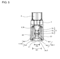
Fig. 5 is a partially enlarged plan view showing the vicinity of one end of the cutting insert according to the first embodiment of the present invention; -
Fig. 6(a) is a plan view showing a cutting insert according to a second embodiment of the present invention; Fig. 2(b) is a side view thereof; -
Fig. 7(a) is a partially enlarged perspective view showing the vicinity of one end of the cutting insert according to the second embodiment of the present invention;Fig. 7(b) is a plan view thereof; -
Fig. 8(a) is a diagram showing an enlarged broken section taken along the line C-C inFig. 7(b) ;Fig. 8(b) is a diagram showing an enlarged broken section taken along the line D-D inFig. 7(b) ;Fig. 8(c) is a diagram showing an enlarged broken section taken along the line E-E inFig. 7(b) ; -
Fig. 9 is a diagram showing an enlarged broken section taken along the line F-F inFig. 7(b) ; -
Fig. 10 is an enlarged front view showing the cutting insert according to the second embodiment of the present invention; -
Fig. 11 is a perspective view showing a cutting tool according to an embodiment of the present invention; -
Figs. 12(a) to 12(c) are schematic explanatory drawings showing a method of manufacturing a machined product according to a first embodiment of the present invention; and -
Figs. 13(a) and 13(b) are schematic explanatory drawings showing a method of manufacturing a machined product according to a second embodiment of the present invention. - The cutting insert according to the first embodiment of present invention is described in detail below with reference to
Figs. 1 to 5 . - The
insert 1 according to the present embodiment is a two-corner type insert with a substantially rectangular column-shaped body as shown inFig. 1 , and is suitably used for cutting-off process, grooving process, or the like, particularly for the grooving process. - The body is a sintered body, such as a cemented carbide, cermet, or ceramics, having a film coated thereon. The film is for improving wear resistance of the body. Examples of the film composition include titanium-based compounds, such as titanium carbide, titanium nitride, and titanium carbonitride; and alumina. The film is required to have at least one layer, or may be made of a plurality of layers. Alternatively, the body may be made of the sintered body not coated with the film.
- The body includes an
upper surface 2, a portion of which has a function of a so-called rake surface; alower surface 10, a portion of which has a function as an attachment surface with respect to a holder; aside surface 15 located between theupper surface 2 and thelower surface 10 in which a portion of the side surface has a function as a so-called flank surface; and twocutting edges upper surface 2 and theside surface 15, and are located at both ends thereof. - As shown in
Fig. 2 , theside surface 15 includes afront flank surface 16 which is positioned at the front of the front end thereof, and is positioned so as to intersect theupper surface 2 and thelower surface 10, respectively; andside flank surfaces - The
cutting edge 20 includes afront cutting edge 21 formed at an intersection region of theupper surface 2 and thefront flank surface 16; andside cutting edges upper surface 2 and theside flank surfaces cutting edge 20, acorner cutting edge 23, which is in a substantially circular arc form in a top view, is formed between thefront cutting edge 21 and theside cutting edge 22 adjacent to each other. Thefront cutting edge 21 and theside cutting edge 22 are continuous with each other with thecorner cutting edge 23 interposed therebetween. - The
upper surface 2 has arake surface 3, a rising surface 7 (rising inclined surface), and aclamp surface 6 in order from thefront cutting edge 21. Therake surface 3 is the surface along which generated chips graze. Therake surface 3 is continuous with thecutting edge 20. Therake surface 3 includes arake surface 3a formed continuously with thefront cutting edge 21, and arake surface 3b formed continuously with the risingsurface 7, as shown inFig. 3 . - The
clamp surface 6 is the surface clamped to aholder 51 described later, together with thelower surface 10. Theclamp surface 6 is located more inward and at a higher position compared to therake surface 3. In the present specification, the term "inward" denotes inward theinsert 1 with respect to thefront cutting edge 21, that is, toward the chip discharge direction indicated by arrow B inFig. 2 . In the present specification, the term "higher position" denotes locating at a higher position in the thickness direction of theinsert 1 than a comparison object. More specifically, when theinsert 1 is placed on a horizontal surface by using thelower surface 10 as a seating surface, theclamp surface 6 is located at a higher position with reference to thefront cutting edge 21. When it is difficult to place theinsert 1 on the horizontal surface by using thelower surface 10 as the seating surface, theclamp surface 6 is required to lie at a higher position than therake surface 3 with theinsert 1 attached to theholder 51. - The rising
surface 7 is inclined and lying at a higher position as going from therake surface 3 to theclamp surface 6. That is, the risingsurface 7 is inclined so as to separate from thelower surface 10 as going from therake surface 3b to theclamp surface 6. The risingsurface 7 is continuous with therake surface 3b and theclamp surface 6, respectively. - The
rake surface 3 includes a pair of first raisedparts front cutting edge 21, namely, near thecorner cutting edges part 5 extending from one of the pair of first raisedparts 4 and 4 (the first raised part 4A) to the other (the first raisedpart 4B) in a top view (refer toFigs. 2 and5 ). - A
ridge portion 5a (second top end) of the second raisedpart 5 is substantially parallel to thefront cutting edge 21, and both ends thereof are continuous with the first raisedparts part 5 extends from the first raised part 4A to the first raisedpart 4B in a direction substantially parallel to thefront cutting edge 21. In the present specification, the term "theridge portion 5a of the second raisedpart 5" denotes a structure in which the highest portions of the second raisedpart 5 in individual cross sections perpendicular to thefront cutting edge 21 are continuously obtained. - As shown in
Fig. 3 , the second raisedpart 5 includes a firstinclined surface 5b inclined so as to separate from thelower surface 10 as going from thefront cutting edge 21 to theridge portion 5a of the second raisedpart 5; and a secondinclined surface 5c inclined so as to approach thelower surface 10 as going from theridge portion 5a to therake surface 3b. That is, the second raisedpart 5 includes the firstinclined surface 5b inclined at an inclination angle α1 and lying at a higher position as going from thefront cutting edge 21 to theridge portion 5a of the second raisedpart 5; and a secondinclined surface 5c inclined at an inclination angle α2 and lying at a lower position as going from theridge portion 5a to the risingsurface 7. In the present specification, the term "lower position" denotes being located a lower position in the thickness direction of theinsert 1 than a comparison object. More specifically, this is prescribed similarly to the foregoing "higher position." - Both end surfaces of the first
inclined surface 5b and the secondinclined surface 5c are continuous with the first raisedparts insert 1 including therake surface 3 thus configured, generated chips are firstly curled like a spring by therake surface 3a located between thefront cutting edge 21 and the second raisedpart 5, and the firstinclined surface 5b of the second raisedpart 5. As soon as a curling diameter of the chips is increased as the grooving process proceeds, the chips climb over theridge portion 5a of the second raisedpart 5, and are drawn along the secondinclined surface 5c of the second raisedpart 5 onto therake surface 3b located between the second raisedpart 5 and the risingsurface 7. Consequently, even when the workpiece is the material having, for example, rich ductility, the chips are surely contacted with the risingsurface 7, thereby obtaining a large contact area. Accordingly, wear resistance is also increased to allow the chips to be easily divided by an appropriate length. - Further in the present embodiment, the inclination angle α1 of the first
inclined surface 5b is larger than the inclination angle α2 of the secondinclined surface 5c. That is, the inclination angles α1 and α2 have a relationship of α1>α2. This facilitates discharge of the generated chips in the foregoing chip discharge process. The inclination angle α1 of thefirst inclination surface 5b is preferably 20-30°, and the inclination angle α2 of thesecond inclination surface 5c is preferably 5-20°. - In the present specification, the term "inclination angle α1" denotes an angle formed by a line L1 which passes through the
ridge portion 5a of the second raisedpart 5 and is parallel to thelower surface 10, and a virtual extension line L2 of the firstinclined surface 5b in a cross section perpendicular to thefront cutting edge 21. Similarly, the term "inclination angle α2" in the present specification denotes an angle formed by the line L1 and a virtual extension line L3 of the secondinclined surface 5c. - In the rake surfaces 3a and 3b constituting the
rake surface 3, therake surface 3a is inclined so as to approach thelower surface 10 at a predetermined rake angle β as going from thefront cutting edge 21 to the second raisedpart 5. The risingsurface 7 is inclined so as to separate from thelower surface 10 at a predetermined rising angle γ as going fromrake surface 3b to theclamp surface 6. These rake angle β and rising angle γ may be respectively adjusted to an optional angle according to the workpiece. Normally, the rake angle β is approximately 10-30°, and the rising angle γ is 20-45°, preferably approximately 20-40°. Particularly, the rising angle γ is preferably larger than the inclination angle α1. This facilitates the discharge of the generated chips in the foregoing chip discharge process. - In the present specification, the term "rake angle β" denotes an angle formed by a line L4 which passes through the
front cutting edge 21 and is parallel to thelower surface 10, and a virtual extension line L5 of therake surface 3a in the cross section perpendicular to thefront cutting edge 21. In the present specification, the term "rising angle γ" denotes an angle formed by a line L6 which passes through an intersection region of the risingsurface 7 and theclamp surface 6, and is parallel to thelower surface 10, and a virtual extension line L7 of the risingsurface 7 in the cross section perpendicular to thefront cutting edge 21. Therake surface 3b is substantially parallel to thelower surface 10. Therefore, therake surface 3 also includes a surface having a rake angle of 0°. - On the other hand, as shown in
Fig. 4 , theridge portion 5a of the second raisedpart 5 is located lower than a virtual straight line L8 connecting between ridge portions 4a1 and 4b1 (first top ends) of the pair of first raisedparts part 4" denotes a structure in which the highest portions of the first raisedpart 4 in individual cross sections parallel to thefront cutting edge 21 are continuously obtained. Thereby, in the chip discharge process of the grooving process, the chips generated from thefront cutting edge 21 are guided to the chip discharge direction by the first raisedparts part 5, lateral vibration of the chips with respect to the chip discharge direction can be reduced. In the present specification, the term "ridge portions 4a1 and 4b1 of first raisedpart 4" denote ones obtained by connecting the highest position portions of the first raisedpart 4 in the cross section parallel to thefront cutting edge 21. - The ridge portions 4a1, 4b1, and 5a are respectively located at a higher position than the
front cutting edge 21, and are respectively located at a lower position than theclamp surface 6. This allows the cross section of the chips generated by thefront cutting edge 21 to be deformed from a flat shape to a warped shape (U-shape) between therake surface 3a and the firstinclined surface 5b. Consequently, the chips are subjected to so-called machining hardening for increasing the hardness of the chips, thereby making it easier for the chips to be divided. The machining hardened chips climb over theridge portion 5a of the second raisedpart 5, and are surely drawn onto therake surface 3b along the secondinclined surface 5c. Thereafter, upon contact with the risingsurface 7, these chips are divided by the appropriate length and are discharged smoothly. - The pair of first raised
parts side cutting edges Fig. 5 . The second raisedpart 5 is located at substantially a midportion in the longitudinal direction of the first raisedpart 4 in a top view. In the pair of first raisedparts part 5b than a side of thefront cutting edge 21, where W1 is a distance between the ridge portion 4a1 of the first raised part 4A and the ridge portion 4b1 of the first raisedpart 4B; and W2 is a distance between an intersection region 4a2 of the first raised part 4A and a bottom part of therake surface 3, and an intersection region 4b2 of the first raisedpart 4B and the bottom part of therake surface 3. - That is, W1a and W1b have a relationship of W1a<W1b, where W1a is W1 located close to the second raised
part 5; and W1b is W1 located close to thefront cutting edge 21. Similarly, W2a and W2b have a relationship of W2a<W2b, where W2a is W2 located close to the second raisedpart 5; and W2b is W2 located close to thefront cutting edge 21. Both W1 and W2 decrease as going from thefront cutting edge 21 to the second raisedpart 5. - This allows the cross section of the chips to be deformed from the flat shape to the warped shape between the
rake surface 3a and the firstinclined surface 5b. Consequently, the chips are subjected to the so-called machining hardening, thereby making it easier for the chips to be divided. The machining hardened chips climb over theridge portion 5a of the second raisedpart 5, and are surely drawn onto therake surface 3b along the secondinclined surface 5c. Thereafter, upon contact with the risingsurface 7, these chips are divided by the appropriate length and are discharged smoothly. - Both W1 and W2 are larger a side of the rising
surface 7 than a side of the second raisedpart 5. That is, W1a and W1c have a relationship of W1a<W1c, where W1c is W1 located close to the risingsurface 7. Similarly, W2a and W2c have a relationship of W2a<W2c, where W2c is W2 located close to the risingsurface 7. Both W1 and W2 increase as going from the second raisedpart 5 to the risingsurface 7. This makes it difficult for both ends of the chips to contact with the first raisedparts surface 7, thus allowing for large wear resistance needed for dividing the chips. - In the present specification, "W1" denotes a distance between the ridge portions 4a1 and 4b1 in a direction substantially parallel to the
front cutting edge 21 in a top view. Similarly, "W2" denotes a distance between the intersection regions 4a2 and 4b2 in a direction substantially parallel to thefront cutting edge 21 in a top view. In the present specification, the term "intersection regions 4a2 and 4b2" denotes the intersection region located close to the second raisedpart 5 in the intersection regions of the first raisedparts 4A and 4B and the bottom part of therake surface 3. - An insert according to a second embodiment of the present invention is described in detail with reference to
Figs. 6 to 10 . InFigs. 6 to 10 , the same components as the foregoingFigs. 1 to 5 are identified by the same reference numerals, and the description thereof is omitted here. - Similarly to the
insert 1 of the first embodiment, theinsert 31 of the present embodiment is a two-corner type insert with a substantially rectangular column-shaped body as shown inFig. 6 , and is suitably used for cutting-off process, grooving process, or the like, particularly for grooving process. - Two cutting
edges upper surface 32 included in the body. Specifically, as shown inFig. 7 , each cuttingedge 35 includes a front cutting edge 36 (first cutting edge) located close to the front end of the body, and a side cutting edge 37 (second cutting edge) intersecting thefront cutting edge 36. That is, thefront cutting edge 36 and theside cutting edge 37 are positioned so that virtual extension lines of their respective cutting edges intersect each other. - The
front cutting edge 36 is the cutting edge that can be used for groove forming process, namely so-called "grooving process," and corresponds to thefront cutting edge 21 of the first embodiment. Theside cutting edge 37 is the cutting edge that can be used for the process of enlarging the width of a groove formed by thefront cutting edge 36, namely, so-called "traversing process," and corresponds to theside cutting edge 22 of the first embodiment. Theside cutting edge 37 can also be used for the process of smoothing a bottom surface of the groove by cross feed, and is therefore usable when the depth of the groove is larger than the length of theside cutting edge 37. - In the present embodiment, a pair of
side cutting edges 37 are respectively positioned at both end portions of thefront cutting edge 36, and are positioned opposite to each other with thefront cutting edge 36 interposed therebetween. Acorner cutting edge 38 having a substantially circular arc shape in a top view is formed at an intersection region of thefront cutting edge 36 and a virtual extension line of theside cutting edge 37. Thefront cutting edge 36 and theside cutting edge 37 are continuous with each other with thecorner cutting edge 38 interposed therebetween. - A first raised
part 41 extending along theside cutting edge 37 is provided on theupper surface 32. In the present embodiment, the first raisedpart 41 extends from near an end portion of theside cutting edge 37 close to thefront cutting edge 36 to near an end portion thereof close to the risingsurface 7. - In the present embodiment, a front part of the first raised
part 41 located close to thefront cutting edge 36 is shaped so as to separate from theside cutting edge 37 as it separates from thefront cutting edge 36, and a rear part thereof close to the risingsurface 7 is shaped so as to approach theside cutting edge 37 as it separates from the front cutting edge 36 (refer toFig. 7(b) ). Accordingly, a front part of aridge portion 411 of the first raisedpart 41 is shaped so as to separate from theside cutting edge 37 as it separates from thefront cutting edge 36, and a rear part thereof is shaped so as to approach theside cutting edge 37 as it separates from thefront cutting edge 36. That is, theridge portion 411 of the first raisedpart 41 approaches theside cutting edge 37 at it separates from thefront cutting edge 36. This configuration stabilizes the discharge of chips generated by theside cutting edge 37. Specifically, the chips can be discharged in a direction of arrow G shown inFig. 7(b) . Thus, the chips are discharged along the first raisedpart 41, thereby making it difficult for the chips to remain in a machined groove. Therefore, the chip discharge performance is improved. In the present specification, a part of the first raisedpart 41 close to the front end thereof is referred to as a "front part", and a part of the first raisedpart 41 close to the rear end thereof is referred to as a "rear part." - As shown in
Fig. 8(a) , the first raisedpart 41 includes, in a sectional view parallel to thefront cutting edge 36, theridge portion 411; a firstinclined portion 412 which is formed close to theside cutting edge 37, and is inclined and lying at a higher position as going from theupper surface 32 to theridge portion 411, and then reaches theridge portion 411; and a secondinclined portion 413 which is formed on the opposite side of the firstinclined portion 412 with theridge portion 411 interposed therebetween, and gradually approaches theupper surface 32. Theridge portion 411 corresponds to an intersection region of the firstinclined portion 412 and the secondinclined portion 413. - The first
inclined portion 412 performs a role in guiding the chips generated from theside cutting edge 37 to a chip discharge direction. Specifically, the chips generated by theside cutting edge 37 are stably discharged in the direction of arrow G shown inFig. 7(b) , along the firstinclined portion 412 while being curled in a helical shape by the firstinclined portion 412. Therefore, particularly in machining a narrow-width groove in which the chips are likely to remain in a machined groove, the chips are less likely to remain the machined groove, and are discharged satisfactorily. Additionally, "trapping" that the chips are trapped between a machined surface and the cutting edge can be reduced, thereby reducing damage to the machine surface. Furthermore, the firstinclined portion 412 has an inclination that rises from theupper surface 32, in a range from near theside cutting edge 37 to theridge portion 411, thereby contributing to a reduction in the cutting resistance of theside cutting edge 37. - The first raised
part 41 is inclined and lying at a lower position toward a rear part thereof (one end portion thereof) that is remote from thefront cutting edge 36 in a side view. That is, the rear part of the first raisedpart 41 has a smaller distance from thelower surface 10 as it separates from thefront cutting edge 36 in the side view. Accordingly, as shown inFigs. 8(a) to 8(c) , a front part of theridge portion 411 is located at a higher position as it separates from thefront cutting edge 36, and a rear part thereof is located at a lower position as it separates from thefront cutting edge 36. - For example, a portion lying at a higher position as it separates from the
front cutting edge 36 has a relationship of Wa<Wb, where Wa and Wb are respectively a distance between theridge portion 411 and a reference line L10. Here, the reference line L10 is a line that passes through theside cutting edge 37 and is parallel to thelower surface 10. A portion lying at a lower position as it separates from thefront cutting edge 36 has a relationship of Wb>Wc, where Wc is a distance between theridge portion 411 and the reference line L10. In the present embodiment, Wa and Wc are respectively zero. However, no special limitation is imposed on a height of Wa and Wc. - The first raised
part 41 having the rear part can suppress an increase in the cutting resistance of theside cutting edge 37 even when a depth of cut of theside cutting edge 37 is increased in the crosscut milling process. In the present specification, the term "depth of cut" denotes a length of a portion of thecutting edge 35 which is brought into contact with the workpiece. - As shown in
Fig. 7 , the first raisedpart 41 includes anapproach portion 415 that approaches theside cutting edge 37 as it separates from thefront cutting edge 36 in a top view. Consequently, during the traversing process, the chips generated by theside cutting edge 37 are satisfactorily discharged along the first raisedpart 41, and are divided by the appropriate length. Hence, the chips are less likely to remain in the machined groove of the workpiece, thereby reducing damage to the workpiece and the insert due to the chips. - The position of the
approach portion 415 may be set according to the depth of cut of theside cutting edge 37. Although no special limitation is imposed thereon, the approach portion is preferably positioned near the rear part of the first raisedpart 41 from the viewpoint of improving the chip discharge. In the present embodiment, theapproach portion 415 includes one of both end portions of the first raisedpart 41 which is remote from thefront cutting edge 36. - In the
approach portion 415, a lower end portion of the firstinclined portion 412 close to theside cutting edge 37 approaches theside cutting edge 37 as it separates from thefront cutting edge 36. That is, as shown inFig. 7(b) , theapproach portion 15 is shaped so as to approach theside cutting edge 37 as anintersection region 414 of the firstinclined portion 412 and theupper surface 32 separates from thefront cutting edge 36 in a top view. In the present embodiment, the front part of theintersection region 414 is shaped so as to separate from theside cutting edge 37 as it separate from thefront cutting edge 36, and the rear part thereof is shaped so as to approach theside cutting edge 37 as it separates from thefront cutting edge 36. - In the present embodiment, a pair of first raised
parts 41 are disposed on theupper surface 32, and are horizontally symmetrically arranged along the pair ofside cutting edges parts front cutting edge 36. For example, in the grooving process in which a cutting process is carried out by thefront cutting edge 36, this region acts to deform the cross section of chips generated from thefront cutting edge 36 into a U-shape. This is advantageous in facilitating curling of the chips. - A
concave part 42 is formed between the first raisedpart 41 and theside cutting edge 37. In the present embodiment, as shown inFig. 7(b) , theconcave part 42 is formed in the shape of a groove. As shown inFigs. 8(a) to 8(c) , asidewall surface 421 of theconcave part 42 close to theside cutting edge 37 has an inclination that approaches thelower surface 10 as going from theside cutting edge 37 to the first raisedpart 41. Theconcave part 42 can contribute to the chip discharge performance improvement because the chips generated by theside cutting edge 37 graze the concave part and are thus previously bent helically. - Other configurations of the
insert 31 are similar to those of theinsert 1 of the foregoing first embodiment. That is, theupper surface 32 of theinsert 31 includes, besides the first raisedpart 41, therake surface 3, the risingsurface 7, theclamp surface 6, and the second raisedpart 5. - As shown in
Fig. 9 , inclination angles α1 and α2 have a relationship of α1>α2. Therake surface 3a is inclined to approach thelower surface 10 at a predetermined rake angle ß as going from thefront cutting edge 36 to the second raisedpart 5. The risingsurface 7 is inclined so as to separate from thelower surface 10 at a predetermined rising angle γ as going from therake surface 3b to theclamp surface 6. - As shown in
Fig. 10 , aridge portion 5a of the second raisedpart 5 is located below a virtual straight line L8 connectingridge portions parts ridges portions front cutting edge 36, and are located at a lower position than theclamp surface 6. - The foregoing inserts 1 and 31 are applicable to both internal grooving process (internal turning) and external grooving process (external turning).
- Next, a cutting tool according to one embodiment of the present invention is described in detail with reference to
Fig. 11 .
As shown inFig. 11 , the cuttingtool 50 according to the present embodiment includes theinsert 1 and a substantially rectangular column-shapedholder 51 configured to attach theinsert 1 to the front end thereof. Theinsert 1 is attached to theholder 51 so that the cutting edge 20 (front cutting edge 21) thereof protrudes from the front end of theholder 51. - In the present embodiment, the attachment of the
insert 1 to theholder 51 is carried out by aclamp mechanism 52 configured to adjust a clamp disposed at the front end of theholder 51 by ascrew 53. More specifically, a constraining force is adjusted by thescrew 53 disposed at the front end of theholder 51, and theinsert 1 is constrained by pressing it from above, without limitation thereto. Examples other than theclamp mechanism 52 include a method in which a hole is provided in theinsert 1, and theinsert 1 is constrained from an inner wall of the hole of theinsert 1 by leverage of a substantially L-shaped lever; and a method in which theinsert 1 is constrained by using a pin with eccentric shaft and head, and by utilizing a hole provided in the insert. - A similar effect is attainable by using the
insert 31 instead of theinsert 1 as an insert attached to theholder 51. - A method of manufacturing a machined product according to a first embodiment of the present invention is described in detail below with reference to
Fig. 12 , by taking the case of performing the outer diameter grooving process by attaching theinsert 1. - The method of manufacturing the machined product according to the present embodiment by using a
cutting tool 50 includes the following steps (i) to (iii). - (i) rotating a
workpiece 100 in a direction of arrow H, as shown inFig. 12(a) ; - (ii) bringing the
cutting edge 20 of thecutting tool 50 into contact with therotating workpiece 100 as shown inFig. 12(b) by moving thecutting tool 50 in a direction of arrow I, as shown inFig. 12(a) , thereby cutting the workpiece 100 (the outer diameter grooving); and - (iii) separating the
cutting tool 50 from theworkpiece 100 by moving thecutting tool 50 in a direction of arrow J, as shown inFig. 12(c) .
A desired machined product is obtainable by cutting theworkpiece 100 in the foregoing manner. - In the present embodiment, the
workpiece 100 is cut with the cuttingtool 50 having excellent chip discharge performance and machined surface accuracy. Therefore, particularly in the step (ii), high cutting performance machining is attainable, thus improving machining efficiency. Even when theworkpiece 100 is a material having rich ductility, excellent chip discharge performance can be exhibited, thereby allowing for stable cutting process over a long term. Examples of theworkpiece 100 having rich ductility include austenitic stainless steels, such as SUS304; and chromium molybdenum steels, such as SCM415. - In the step (i), the
workpiece 100 and thecutting tool 50 may be close to each other. For example, theworkpiece 100 may be brought near the cuttingtool 50. Similarly, in the step (iii), theworkpiece 100 and thecutting tool 50 may be far away from each other. For example, theworkpiece 100 may be moved away from the cuttingtool 50. When the cutting process is continued, it is required to repeat the step of bringing thecutting edge 20 of thecutting tool 50 into contact with different portions of theworkpiece 100 while holding the rotation of theworkpiece 100. As stated earlier, theinsert 1 is the two-corner type insert. Hence, when thecutting edge 20 in use is worn, anunused cutting edge 20 may be used.
A similar effect is attainable by using theinsert 31 instead of theinsert 1 as an insert attached to theholder 51. - Next, a method of manufacturing a machined product according to a second embodiment of the present invention is described in detail below with reference to
Fig. 13 , by taking the case of performing the outer diameter grooving process by attaching theinsert 31. - The
insert 31 of the present embodiment permits a smooth crosscut milling process for enlarging a groove width, besides the grooving process for forming a groove. - Firstly, as the traversing process for enlarging the width of the groove, usually, the steps of the grooving process as shown in
Figs. 12(a) to 12(c) are required to be repetitively performed in a lateral direction. As a result, somewhat irregularity may be formed on abottom surface 101 of the enlarged groove, as shown inFig. 13(a) . - Subsequently, by moving a
cutting tool 55 in a direction of arrow K as shown inFig. 13(a) , thebottom surface 101 of the groove can be flattened as shown inFig. 13(b) .
A desired machined product is obtainable by cutting theworkpiece 100 in the foregoing manner (crosscut milling process). - With the
cutting tool 55 having theinsert 31 attached to theholder 51, because the first raisedpart 41 of theinsert 31 includes theapproach portion 415, thebottom surface 101 of the groove can be flattened while smoothly discharging the chips, by moving thecutting tool 55 in a direction of arrow K. - As an insert attached to the
holder 51, theinsert 1 may be used instead of theinsert 31. That is, either theinsert 1 or theinsert 31 may be used in the cutting process in combination of the method of manufacturing a machined product according to the first embodiment and the method of manufacturing a machined product according to the second embodiment, as described above. - While the several embodiments according to the present invention have been described and illustrated above, it is to be understood that the present invention is not limited to the foregoing embodiments, and various improvements and changes can be made within the scope of the appended claims.
- Although the
inserts inserts inserts - In the
insert 1 according to the first embodiment, the description has been given of the case where both W1 and W2 decrease as going from thecutting edge 20 to the second raisedpart 5, and are increased from the second raisedpart 5 to the risingsurface 7. That is, in the first embodiment, the description has been given of the case where both W1 and W2 gradually change toward the predetermined direction. For example, W1 and W2 may be configured so that W1 and W2 do not change gradually, and both are smaller a side of the second raisedpart 5 than a side of thecutting edge 20, and both are larger a side of the risingsurface 7 than a side of the second raisedpart 5.
Claims (22)
- A cutting insert, comprising:an upper surface;a side surface; anda cutting edge located at an intersection region of the upper surface and the side surface,
whereinthe upper surface comprises
a rake surface continuous with the cutting edge, and
a rising surface inclined and lying at a higher position as going inward from the rake surface, andthe rake surface comprises
a pair of first raised parts respectively extending inward from near both ends of the cutting edge in a top view, and
a second raised part extending from one of the pair of first raised parts to the other. - The cutting insert according to claim 1, wherein a ridge portion of the second raised part is parallel to the cutting edge in a top view.
- The cutting insert according to claim 1 or 2, wherein the second raised part comprises
a first inclined surface inclined at an inclination angle α1 and lying at a higher position as going from the cutting edge to the ridge portion of the second raised part, and
a second inclined surface inclined at an inclination angle α2 and lying at a lower position as going from the ridge portion of the second raised part to the rising surface. - The cutting insert according to claim 3, wherein the inclination angle α1 of the first inclined surface is larger than the inclination angle α2 of the second inclined surface.
- The cutting insert according to claim 4, wherein a rising angle γ of the rising surface is larger than the inclination angle α1 of the first inclined surface.
- The cutting insert according to any one of claims 1 to 5, wherein the ridge portion of the second raised part is located below a virtual straight line connecting respective ridge portions of the pair of first raised parts in a side view.
- The cutting insert according to any one of claims 1 to 6,
wherein both W1 and W2 in each of the pair of first raised parts are smaller at a side of the second raised part than a side of the cutting edge, where
W1 is a distance between the ridge portion of one of the first raised parts and the other ridge portion, and
W2 is a distance between an intersection region of the one first raised part and a bottom part of the rake surface, and an intersection region of the other first raised part and the bottom part of the rake surface. - The cutting insert according to claim 7, wherein both the W1 and the W2 decrease as going from the cutting edge to the second raised part.
- The cutting insert according to claim 7 or 8, wherein both the W1 and W2 are larger a side of the rising surface than the side of the second raised part.
- The cutting insert according to any one of claims 7 to 9, wherein both the W1 and the W2 increase as going from the second raised part to the rising surface.
- The cutting insert according to claim 1, wherein
the cutting edge comprises a first cutting edge and a second cutting edge intersecting each other, and
at least one of the pair of first raised parts comprises an approach portion, wherein the approach portion extends along the second cutting edge and approaches the second cutting edge as separating from the first cutting edge. - The cutting insert according to claim 11, wherein the approach portion comprises an end portion of the at least one of the plurality of the first raised parts, the end portion being further away from the first cutting edge.
- The cutting insert according to claim 11 or 12, wherein the at least one first raised part comprises an inclined portion inclined and lying at a higher position as going from the second cutting edge to the ridge portion of the at least one of the plurality of the first raised parts.
- The cutting insert according to claim 13, wherein the approach portion further comprises an end portion of the inclined portion, the end portion being further away from the first cutting edge.
- The cutting insert according to claim 13 or 14, wherein the approach portion further comprises a lower end of the inclined portion, the lower end being closer to the second cutting edge.
- The cutting insert according to any one of claims 11 to 15, wherein the approach portion includes the ridge portion of the at least one of the plurality of the first raised parts.
- The cutting insert according to any one of claims 11 to 16, wherein the at least one of the plurality of the first raised parts is inclined and lying at a lower position as going to the end portion further away from the first cutting edge in a side view.
- The cutting insert according to any one of claims 11 to 17, wherein a pair of the second cutting edges are respectively disposed on both sides of the first cutting edge.
- The cutting insert according to claim 18, wherein the pair of first raised parts are disposed symmetrical to each other along the pair of second cutting edges in a top view.
- The cutting insert according to any one of claims 1 to 19, wherein the upper surface further comprises a clamp surface positioned inward compared to the rising surface.
- A cutting tool, comprising:a cutting insert according to any one of claims 1 to 20; anda holder configured to attach the cutting insert to a front end thereof.
- A method of manufacturing a machined product, comprising:rotating a workpiece;bringing the workpiece being rotated and the cutting edge of the cutting tool according to claim 21 into contact with each other; andseparating the workpiece and the cutting tool from each other.
Applications Claiming Priority (3)
| Application Number | Priority Date | Filing Date | Title |
|---|---|---|---|
| JP2009249106 | 2009-10-29 | ||
| JP2009270862 | 2009-11-28 | ||
| PCT/JP2010/069132 WO2011052667A1 (en) | 2009-10-29 | 2010-10-28 | Cutting insert, cutting tool, and method for manufacturing cut product using the cutting tool |
Publications (3)
| Publication Number | Publication Date |
|---|---|
| EP2495058A1 true EP2495058A1 (en) | 2012-09-05 |
| EP2495058A4 EP2495058A4 (en) | 2014-04-30 |
| EP2495058B1 EP2495058B1 (en) | 2018-05-16 |
Family
ID=43922089
Family Applications (1)
| Application Number | Title | Priority Date | Filing Date |
|---|---|---|---|
| EP10826799.8A Active EP2495058B1 (en) | 2009-10-29 | 2010-10-28 | Cutting insert |
Country Status (5)
| Country | Link |
|---|---|
| US (1) | US8784014B2 (en) |
| EP (1) | EP2495058B1 (en) |
| JP (1) | JP5438771B2 (en) |
| CN (1) | CN102596459B (en) |
| WO (1) | WO2011052667A1 (en) |
Cited By (4)
| Publication number | Priority date | Publication date | Assignee | Title |
|---|---|---|---|---|
| US20120282046A1 (en) * | 2010-01-07 | 2012-11-08 | Alan Taylor | Machining tool and method of manufacturing same |
| EP3213843A4 (en) * | 2014-10-28 | 2018-07-18 | NGK Spark Plug Co., Ltd. | Cutting insert |
| WO2020115088A1 (en) * | 2018-12-04 | 2020-06-11 | Hartmetall-Werkzeugfabrik Paul Horn Gmbh | Cutting plate and tool for machining a workpiece |
| DE112016004043B4 (en) | 2015-09-07 | 2023-12-07 | Kyocera Corporation | Cutting insert, cutting tool and method of producing a machined product |
Families Citing this family (20)
| Publication number | Priority date | Publication date | Assignee | Title |
|---|---|---|---|---|
| JP5639656B2 (en) * | 2010-09-29 | 2014-12-10 | 京セラ株式会社 | Cutting insert, cutting tool, and method of manufacturing a cut product using the same |
| JP5869687B2 (en) * | 2012-09-27 | 2016-02-24 | 京セラ株式会社 | Cutting inserts and cutting tools |
| JP6038594B2 (en) | 2012-10-26 | 2016-12-07 | 住友電工ハードメタル株式会社 | Parting tool |
| JP6206801B2 (en) * | 2013-09-09 | 2017-10-04 | 住友電工ハードメタル株式会社 | Cutting insert |
| JP6495681B2 (en) * | 2015-02-24 | 2019-04-03 | 京セラ株式会社 | Cutting insert, cutting tool, and manufacturing method of cut workpiece |
| US9901986B2 (en) * | 2016-02-15 | 2018-02-27 | Iscar, Ltd. | Swiss turning insert with chip former arrangement comprising upwardly extending ridge |
| JP6798663B2 (en) * | 2016-04-27 | 2020-12-09 | 住友電工ハードメタル株式会社 | Cutting insert |
| JP6069566B1 (en) * | 2016-06-27 | 2017-02-01 | シモダフランジ株式会社 | Screw machining tool and screw machining method |
| WO2018079491A1 (en) * | 2016-10-31 | 2018-05-03 | 京セラ株式会社 | Cutting insert, cutting tool, and manufacturing method for cut machined workpieces |
| US10384268B1 (en) | 2018-02-05 | 2019-08-20 | Iscar, Ltd. | Grooving insert having rearwardly pointing arrowhead-shaped chip former |
| CN113613816B (en) * | 2019-03-29 | 2023-10-03 | 京瓷株式会社 | Cutting insert, cutting tool and method for manufacturing cutting workpiece |
| JP6733784B1 (en) * | 2019-06-28 | 2020-08-05 | 株式会社タンガロイ | Cutting insert and cutting tool |
| CN111730079B (en) * | 2020-07-21 | 2025-04-01 | 北京沃尔德金刚石工具股份有限公司 | A new chip breaker slot cutter |
| US11806793B2 (en) | 2021-11-03 | 2023-11-07 | Iscar, Ltd. | Cutting insert having laterally spaced apart, longitudinally extending wedge abutment surfaces, tool holder and cutting tool |
| US12275078B2 (en) | 2022-05-03 | 2025-04-15 | Iscar, Ltd. | Rotationally asymmetric double-ended grooving cutting insert, insert holder and cutting tool |
| US12465981B2 (en) * | 2022-09-07 | 2025-11-11 | Iscar, Ltd. | Cemented carbide cutting insert for parting metal workpieces |
| JP7269540B1 (en) * | 2022-09-28 | 2023-05-09 | 株式会社タンガロイ | cutting insert |
| CN115958215A (en) * | 2022-12-21 | 2023-04-14 | 厦门金鹭特种合金有限公司 | Cutting insert and cutting tool |
| CN118720193A (en) * | 2023-03-30 | 2024-10-01 | 京瓷株式会社 | Cutting insert |
| JPWO2025063055A1 (en) * | 2023-09-20 | 2025-03-27 |
Family Cites Families (20)
| Publication number | Priority date | Publication date | Assignee | Title |
|---|---|---|---|---|
| US4181456A (en) * | 1978-01-06 | 1980-01-01 | Niagara Cutter Inc. | Cutting tool |
| US4195956A (en) * | 1978-08-01 | 1980-04-01 | Wlajko Mihic | Slotting tool with exchangeable cutting insert |
| US4583887A (en) * | 1979-12-04 | 1986-04-22 | Iscar Ltd. | Rotary slot cutting tools |
| DE3906822C3 (en) * | 1989-03-03 | 1996-11-21 | Zinner Gmbh Praezisionswerkzeu | Holder for cutting tool inserts |
| CN1025661C (en) * | 1990-02-07 | 1994-08-17 | 伊斯卡硬金属股份有限公司 | Aetal cutting insert |
| SE508121C2 (en) | 1992-04-30 | 1998-08-31 | Sandvik Ab | Cutter for turning and groove knitting tools |
| GB2290994B (en) * | 1994-07-05 | 1998-06-10 | Valenite Inc | Cutting insert |
| US5704737A (en) | 1995-04-20 | 1998-01-06 | Kennametal Inc. | Cutting insert with chip control |
| DE69802998T2 (en) * | 1997-03-27 | 2002-07-18 | Sandvik Ab, Sandviken | Grooving and parting tool |
| US6742971B2 (en) * | 2002-02-19 | 2004-06-01 | Manchester Tool Company | Cutting insert |
| US7883300B1 (en) * | 2002-10-18 | 2011-02-08 | Kennametal Inc. | Tool holder and metal cutting insert with chip breaking surfaces |
| DE10344961A1 (en) * | 2003-09-27 | 2005-04-28 | Kennametal Inc | Cutting body, in particular for lancing and longitudinal turning |
| IL159188A (en) * | 2003-12-04 | 2008-08-07 | Uzi Gati | Cutting insert for grooving operations |
| JP2005288613A (en) | 2004-03-31 | 2005-10-20 | Mitsubishi Materials Corp | Throwaway tip |
| JP5217449B2 (en) * | 2007-03-30 | 2013-06-19 | 三菱マテリアル株式会社 | Cutting insert |
| CN101274371A (en) * | 2007-03-30 | 2008-10-01 | 三菱麻铁里亚尔株式会社 | Cutting insert |
| KR20100014870A (en) * | 2007-04-20 | 2010-02-11 | 미쓰비시 마테리알 가부시키가이샤 | Cutting insert, and cutting method |
| IL192785A0 (en) * | 2007-10-22 | 2009-02-11 | Gershon Harif | Cutting tool with protrusions, and methods of use thereof |
| KR101115657B1 (en) * | 2009-07-01 | 2012-02-15 | 한국야금 주식회사 | Grooving insert |
| US9033622B2 (en) * | 2012-01-03 | 2015-05-19 | Iscar, Ltd. | Cutting insert having curved ramps for insertion into a tool holder, cutting tool and method of assembly |
-
2010
- 2010-10-28 WO PCT/JP2010/069132 patent/WO2011052667A1/en not_active Ceased
- 2010-10-28 US US13/504,606 patent/US8784014B2/en active Active
- 2010-10-28 JP JP2011538469A patent/JP5438771B2/en active Active
- 2010-10-28 EP EP10826799.8A patent/EP2495058B1/en active Active
- 2010-10-28 CN CN201080048489.XA patent/CN102596459B/en active Active
Cited By (6)
| Publication number | Priority date | Publication date | Assignee | Title |
|---|---|---|---|---|
| US20120282046A1 (en) * | 2010-01-07 | 2012-11-08 | Alan Taylor | Machining tool and method of manufacturing same |
| US9242299B2 (en) * | 2010-01-07 | 2016-01-26 | Gkn Sinter Metals, Llc | Machining tool and method of manufacturing same |
| EP3213843A4 (en) * | 2014-10-28 | 2018-07-18 | NGK Spark Plug Co., Ltd. | Cutting insert |
| DE112016004043B4 (en) | 2015-09-07 | 2023-12-07 | Kyocera Corporation | Cutting insert, cutting tool and method of producing a machined product |
| WO2020115088A1 (en) * | 2018-12-04 | 2020-06-11 | Hartmetall-Werkzeugfabrik Paul Horn Gmbh | Cutting plate and tool for machining a workpiece |
| US11958117B2 (en) | 2018-12-04 | 2024-04-16 | Hartmetall-Werkzeugfabrik Paul Horn Gmbh | Cutting insert and tool for machining a workpiece |
Also Published As
| Publication number | Publication date |
|---|---|
| US8784014B2 (en) | 2014-07-22 |
| WO2011052667A1 (en) | 2011-05-05 |
| JP5438771B2 (en) | 2014-03-12 |
| JPWO2011052667A1 (en) | 2013-03-21 |
| US20120210834A1 (en) | 2012-08-23 |
| CN102596459A (en) | 2012-07-18 |
| EP2495058B1 (en) | 2018-05-16 |
| EP2495058A4 (en) | 2014-04-30 |
| CN102596459B (en) | 2015-07-15 |
Similar Documents
| Publication | Publication Date | Title |
|---|---|---|
| EP2495058B1 (en) | Cutting insert | |
| US9205495B2 (en) | Cutting insert, cutting tool, and method of manufacturing machined product using them | |
| US9108248B2 (en) | Cutting insert, cutting tool, and method of manufacturing machined product using them | |
| US8998542B2 (en) | Cutting insert, cutting tool, and method of manufacturing machined product using them | |
| US8770895B2 (en) | Cutting insert, cutting tool, and method of cutting workpiece using them | |
| EP2623236B1 (en) | Cutting insert, cutting tool with said cutting insert, and method for producing cut product using said cutting tool | |
| US10232445B2 (en) | Cutting insert, cutting tool, and method for manufacturing machined product | |
| JP2007516844A (en) | Cutting insert for high speed feed face milling | |
| WO2013065393A1 (en) | Cutting insert, cutting tool, and method for manufacturing cut product using cutting tool | |
| CN104136158A (en) | Cutting insert, cutting tool, and method for manufacturing cut product | |
| US20210260669A1 (en) | Cutting insert, cutting tool, and method for manufacturing machined product | |
| US11161178B2 (en) | Cutting insert, cutting tool, and method of manufacturing machined product | |
| US12128483B2 (en) | Cutting insert, cutting tool and method for manufacturing machined product | |
| US11305358B2 (en) | Cutting insert, cutting tool, and method for manufacturing machined product | |
| WO2018159499A1 (en) | Cutting insert, cutting tool, and method for manufacturing cut workpiece | |
| CN111601675A (en) | Cutting insert, cutting tool, and manufacturing method of machined product | |
| JP7344376B2 (en) | Manufacturing method for cutting inserts, cutting tools and cut products | |
| JP5595163B2 (en) | Cutting insert, cutting tool, and cutting method of work material using them | |
| JP2019130647A (en) | Cutting insert, cutting tool and manufacturing method of cutting work object | |
| CN121866128A (en) | Cutting insert, cutting tool, and method for manufacturing cut product |
Legal Events
| Date | Code | Title | Description |
|---|---|---|---|
| PUAI | Public reference made under article 153(3) epc to a published international application that has entered the european phase |
Free format text: ORIGINAL CODE: 0009012 |
|
| 17P | Request for examination filed |
Effective date: 20120529 |
|
| AK | Designated contracting states |
Kind code of ref document: A1 Designated state(s): AL AT BE BG CH CY CZ DE DK EE ES FI FR GB GR HR HU IE IS IT LI LT LU LV MC MK MT NL NO PL PT RO RS SE SI SK SM TR |
|
| DAX | Request for extension of the european patent (deleted) | ||
| A4 | Supplementary search report drawn up and despatched |
Effective date: 20140328 |
|
| RIC1 | Information provided on ipc code assigned before grant |
Ipc: B23B 27/04 20060101ALI20140324BHEP Ipc: B23B 27/22 20060101AFI20140324BHEP |
|
| GRAP | Despatch of communication of intention to grant a patent |
Free format text: ORIGINAL CODE: EPIDOSNIGR1 |
|
| INTG | Intention to grant announced |
Effective date: 20171206 |
|
| GRAS | Grant fee paid |
Free format text: ORIGINAL CODE: EPIDOSNIGR3 |
|
| GRAA | (expected) grant |
Free format text: ORIGINAL CODE: 0009210 |
|
| AK | Designated contracting states |
Kind code of ref document: B1 Designated state(s): AL AT BE BG CH CY CZ DE DK EE ES FI FR GB GR HR HU IE IS IT LI LT LU LV MC MK MT NL NO PL PT RO RS SE SI SK SM TR |
|
| REG | Reference to a national code |
Ref country code: GB Ref legal event code: FG4D |
|
| REG | Reference to a national code |
Ref country code: CH Ref legal event code: EP |
|
| REG | Reference to a national code |
Ref country code: IE Ref legal event code: FG4D |
|
| REG | Reference to a national code |
Ref country code: DE Ref legal event code: R096 Ref document number: 602010050698 Country of ref document: DE |
|
| REG | Reference to a national code |
Ref country code: AT Ref legal event code: REF Ref document number: 999079 Country of ref document: AT Kind code of ref document: T Effective date: 20180615 |
|
| REG | Reference to a national code |
Ref country code: NL Ref legal event code: MP Effective date: 20180516 |
|
| REG | Reference to a national code |
Ref country code: LT Ref legal event code: MG4D |
|
| PG25 | Lapsed in a contracting state [announced via postgrant information from national office to epo] |
Ref country code: ES Free format text: LAPSE BECAUSE OF FAILURE TO SUBMIT A TRANSLATION OF THE DESCRIPTION OR TO PAY THE FEE WITHIN THE PRESCRIBED TIME-LIMIT Effective date: 20180516 Ref country code: BG Free format text: LAPSE BECAUSE OF FAILURE TO SUBMIT A TRANSLATION OF THE DESCRIPTION OR TO PAY THE FEE WITHIN THE PRESCRIBED TIME-LIMIT Effective date: 20180816 Ref country code: LT Free format text: LAPSE BECAUSE OF FAILURE TO SUBMIT A TRANSLATION OF THE DESCRIPTION OR TO PAY THE FEE WITHIN THE PRESCRIBED TIME-LIMIT Effective date: 20180516 Ref country code: FI Free format text: LAPSE BECAUSE OF FAILURE TO SUBMIT A TRANSLATION OF THE DESCRIPTION OR TO PAY THE FEE WITHIN THE PRESCRIBED TIME-LIMIT Effective date: 20180516 Ref country code: SE Free format text: LAPSE BECAUSE OF FAILURE TO SUBMIT A TRANSLATION OF THE DESCRIPTION OR TO PAY THE FEE WITHIN THE PRESCRIBED TIME-LIMIT Effective date: 20180516 Ref country code: NO Free format text: LAPSE BECAUSE OF FAILURE TO SUBMIT A TRANSLATION OF THE DESCRIPTION OR TO PAY THE FEE WITHIN THE PRESCRIBED TIME-LIMIT Effective date: 20180816 |
|
| PG25 | Lapsed in a contracting state [announced via postgrant information from national office to epo] |
Ref country code: RS Free format text: LAPSE BECAUSE OF FAILURE TO SUBMIT A TRANSLATION OF THE DESCRIPTION OR TO PAY THE FEE WITHIN THE PRESCRIBED TIME-LIMIT Effective date: 20180516 Ref country code: LV Free format text: LAPSE BECAUSE OF FAILURE TO SUBMIT A TRANSLATION OF THE DESCRIPTION OR TO PAY THE FEE WITHIN THE PRESCRIBED TIME-LIMIT Effective date: 20180516 Ref country code: HR Free format text: LAPSE BECAUSE OF FAILURE TO SUBMIT A TRANSLATION OF THE DESCRIPTION OR TO PAY THE FEE WITHIN THE PRESCRIBED TIME-LIMIT Effective date: 20180516 Ref country code: GR Free format text: LAPSE BECAUSE OF FAILURE TO SUBMIT A TRANSLATION OF THE DESCRIPTION OR TO PAY THE FEE WITHIN THE PRESCRIBED TIME-LIMIT Effective date: 20180817 Ref country code: NL Free format text: LAPSE BECAUSE OF FAILURE TO SUBMIT A TRANSLATION OF THE DESCRIPTION OR TO PAY THE FEE WITHIN THE PRESCRIBED TIME-LIMIT Effective date: 20180516 |
|
| REG | Reference to a national code |
Ref country code: AT Ref legal event code: MK05 Ref document number: 999079 Country of ref document: AT Kind code of ref document: T Effective date: 20180516 |
|
| PG25 | Lapsed in a contracting state [announced via postgrant information from national office to epo] |
Ref country code: RO Free format text: LAPSE BECAUSE OF FAILURE TO SUBMIT A TRANSLATION OF THE DESCRIPTION OR TO PAY THE FEE WITHIN THE PRESCRIBED TIME-LIMIT Effective date: 20180516 Ref country code: CZ Free format text: LAPSE BECAUSE OF FAILURE TO SUBMIT A TRANSLATION OF THE DESCRIPTION OR TO PAY THE FEE WITHIN THE PRESCRIBED TIME-LIMIT Effective date: 20180516 Ref country code: SK Free format text: LAPSE BECAUSE OF FAILURE TO SUBMIT A TRANSLATION OF THE DESCRIPTION OR TO PAY THE FEE WITHIN THE PRESCRIBED TIME-LIMIT Effective date: 20180516 Ref country code: PL Free format text: LAPSE BECAUSE OF FAILURE TO SUBMIT A TRANSLATION OF THE DESCRIPTION OR TO PAY THE FEE WITHIN THE PRESCRIBED TIME-LIMIT Effective date: 20180516 Ref country code: AT Free format text: LAPSE BECAUSE OF FAILURE TO SUBMIT A TRANSLATION OF THE DESCRIPTION OR TO PAY THE FEE WITHIN THE PRESCRIBED TIME-LIMIT Effective date: 20180516 Ref country code: EE Free format text: LAPSE BECAUSE OF FAILURE TO SUBMIT A TRANSLATION OF THE DESCRIPTION OR TO PAY THE FEE WITHIN THE PRESCRIBED TIME-LIMIT Effective date: 20180516 Ref country code: DK Free format text: LAPSE BECAUSE OF FAILURE TO SUBMIT A TRANSLATION OF THE DESCRIPTION OR TO PAY THE FEE WITHIN THE PRESCRIBED TIME-LIMIT Effective date: 20180516 |
|
| REG | Reference to a national code |
Ref country code: DE Ref legal event code: R097 Ref document number: 602010050698 Country of ref document: DE |
|
| PG25 | Lapsed in a contracting state [announced via postgrant information from national office to epo] |
Ref country code: IT Free format text: LAPSE BECAUSE OF FAILURE TO SUBMIT A TRANSLATION OF THE DESCRIPTION OR TO PAY THE FEE WITHIN THE PRESCRIBED TIME-LIMIT Effective date: 20180516 Ref country code: SM Free format text: LAPSE BECAUSE OF FAILURE TO SUBMIT A TRANSLATION OF THE DESCRIPTION OR TO PAY THE FEE WITHIN THE PRESCRIBED TIME-LIMIT Effective date: 20180516 |
|
| PLBE | No opposition filed within time limit |
Free format text: ORIGINAL CODE: 0009261 |
|
| STAA | Information on the status of an ep patent application or granted ep patent |
Free format text: STATUS: NO OPPOSITION FILED WITHIN TIME LIMIT |
|
| 26N | No opposition filed |
Effective date: 20190219 |
|
| PG25 | Lapsed in a contracting state [announced via postgrant information from national office to epo] |
Ref country code: SI Free format text: LAPSE BECAUSE OF FAILURE TO SUBMIT A TRANSLATION OF THE DESCRIPTION OR TO PAY THE FEE WITHIN THE PRESCRIBED TIME-LIMIT Effective date: 20180516 |
|
| REG | Reference to a national code |
Ref country code: CH Ref legal event code: PL |
|
| GBPC | Gb: european patent ceased through non-payment of renewal fee |
Effective date: 20181028 |
|
| REG | Reference to a national code |
Ref country code: BE Ref legal event code: MM Effective date: 20181031 |
|
| PG25 | Lapsed in a contracting state [announced via postgrant information from national office to epo] |
Ref country code: LU Free format text: LAPSE BECAUSE OF NON-PAYMENT OF DUE FEES Effective date: 20181028 Ref country code: MC Free format text: LAPSE BECAUSE OF FAILURE TO SUBMIT A TRANSLATION OF THE DESCRIPTION OR TO PAY THE FEE WITHIN THE PRESCRIBED TIME-LIMIT Effective date: 20180516 |
|
| REG | Reference to a national code |
Ref country code: IE Ref legal event code: MM4A |
|
| PG25 | Lapsed in a contracting state [announced via postgrant information from national office to epo] |
Ref country code: BE Free format text: LAPSE BECAUSE OF NON-PAYMENT OF DUE FEES Effective date: 20181031 Ref country code: CH Free format text: LAPSE BECAUSE OF NON-PAYMENT OF DUE FEES Effective date: 20181031 Ref country code: FR Free format text: LAPSE BECAUSE OF NON-PAYMENT OF DUE FEES Effective date: 20181031 Ref country code: LI Free format text: LAPSE BECAUSE OF NON-PAYMENT OF DUE FEES Effective date: 20181031 |
|
| PG25 | Lapsed in a contracting state [announced via postgrant information from national office to epo] |
Ref country code: GB Free format text: LAPSE BECAUSE OF NON-PAYMENT OF DUE FEES Effective date: 20181028 Ref country code: IE Free format text: LAPSE BECAUSE OF NON-PAYMENT OF DUE FEES Effective date: 20181028 |
|
| PG25 | Lapsed in a contracting state [announced via postgrant information from national office to epo] |
Ref country code: AL Free format text: LAPSE BECAUSE OF FAILURE TO SUBMIT A TRANSLATION OF THE DESCRIPTION OR TO PAY THE FEE WITHIN THE PRESCRIBED TIME-LIMIT Effective date: 20180516 |
|
| PG25 | Lapsed in a contracting state [announced via postgrant information from national office to epo] |
Ref country code: MT Free format text: LAPSE BECAUSE OF NON-PAYMENT OF DUE FEES Effective date: 20181028 |
|
| PG25 | Lapsed in a contracting state [announced via postgrant information from national office to epo] |
Ref country code: TR Free format text: LAPSE BECAUSE OF FAILURE TO SUBMIT A TRANSLATION OF THE DESCRIPTION OR TO PAY THE FEE WITHIN THE PRESCRIBED TIME-LIMIT Effective date: 20180516 |
|
| PG25 | Lapsed in a contracting state [announced via postgrant information from national office to epo] |
Ref country code: PT Free format text: LAPSE BECAUSE OF FAILURE TO SUBMIT A TRANSLATION OF THE DESCRIPTION OR TO PAY THE FEE WITHIN THE PRESCRIBED TIME-LIMIT Effective date: 20180516 |
|
| PG25 | Lapsed in a contracting state [announced via postgrant information from national office to epo] |
Ref country code: MK Free format text: LAPSE BECAUSE OF NON-PAYMENT OF DUE FEES Effective date: 20180516 Ref country code: HU Free format text: LAPSE BECAUSE OF FAILURE TO SUBMIT A TRANSLATION OF THE DESCRIPTION OR TO PAY THE FEE WITHIN THE PRESCRIBED TIME-LIMIT; INVALID AB INITIO Effective date: 20101028 Ref country code: CY Free format text: LAPSE BECAUSE OF FAILURE TO SUBMIT A TRANSLATION OF THE DESCRIPTION OR TO PAY THE FEE WITHIN THE PRESCRIBED TIME-LIMIT Effective date: 20180516 |
|
| PG25 | Lapsed in a contracting state [announced via postgrant information from national office to epo] |
Ref country code: IS Free format text: LAPSE BECAUSE OF FAILURE TO SUBMIT A TRANSLATION OF THE DESCRIPTION OR TO PAY THE FEE WITHIN THE PRESCRIBED TIME-LIMIT Effective date: 20180916 |
|
| P01 | Opt-out of the competence of the unified patent court (upc) registered |
Effective date: 20230505 |
|
| PGFP | Annual fee paid to national office [announced via postgrant information from national office to epo] |
Ref country code: DE Payment date: 20250902 Year of fee payment: 16 |