EP2494540B1 - Ansteuerung einer elektrobenässungs-anzeigeeinrichtung mit reduzierung von hysteresis-effekten - Google Patents
Ansteuerung einer elektrobenässungs-anzeigeeinrichtung mit reduzierung von hysteresis-effekten Download PDFInfo
- Publication number
- EP2494540B1 EP2494540B1 EP10782566.3A EP10782566A EP2494540B1 EP 2494540 B1 EP2494540 B1 EP 2494540B1 EP 10782566 A EP10782566 A EP 10782566A EP 2494540 B1 EP2494540 B1 EP 2494540B1
- Authority
- EP
- European Patent Office
- Prior art keywords
- display
- fluid
- signal level
- display element
- period
- Prior art date
- Legal status (The legal status is an assumption and is not a legal conclusion. Google has not performed a legal analysis and makes no representation as to the accuracy of the status listed.)
- Active
Links
Images


Classifications
-
- G—PHYSICS
- G09—EDUCATION; CRYPTOGRAPHY; DISPLAY; ADVERTISING; SEALS
- G09G—ARRANGEMENTS OR CIRCUITS FOR CONTROL OF INDICATING DEVICES USING STATIC MEANS TO PRESENT VARIABLE INFORMATION
- G09G3/00—Control arrangements or circuits, of interest only in connection with visual indicators other than cathode-ray tubes
- G09G3/20—Control arrangements or circuits, of interest only in connection with visual indicators other than cathode-ray tubes for presentation of an assembly of a number of characters, e.g. a page, by composing the assembly by combination of individual elements arranged in a matrix no fixed position being assigned to or needed to be assigned to the individual characters or partial characters
- G09G3/34—Control arrangements or circuits, of interest only in connection with visual indicators other than cathode-ray tubes for presentation of an assembly of a number of characters, e.g. a page, by composing the assembly by combination of individual elements arranged in a matrix no fixed position being assigned to or needed to be assigned to the individual characters or partial characters by control of light from an independent source
- G09G3/3433—Control arrangements or circuits, of interest only in connection with visual indicators other than cathode-ray tubes for presentation of an assembly of a number of characters, e.g. a page, by composing the assembly by combination of individual elements arranged in a matrix no fixed position being assigned to or needed to be assigned to the individual characters or partial characters by control of light from an independent source using light modulating elements actuated by an electric field and being other than liquid crystal devices and electrochromic devices
- G09G3/348—Control arrangements or circuits, of interest only in connection with visual indicators other than cathode-ray tubes for presentation of an assembly of a number of characters, e.g. a page, by composing the assembly by combination of individual elements arranged in a matrix no fixed position being assigned to or needed to be assigned to the individual characters or partial characters by control of light from an independent source using light modulating elements actuated by an electric field and being other than liquid crystal devices and electrochromic devices based on the deformation of a fluid drop, e.g. electrowetting
-
- G—PHYSICS
- G09—EDUCATION; CRYPTOGRAPHY; DISPLAY; ADVERTISING; SEALS
- G09G—ARRANGEMENTS OR CIRCUITS FOR CONTROL OF INDICATING DEVICES USING STATIC MEANS TO PRESENT VARIABLE INFORMATION
- G09G3/00—Control arrangements or circuits, of interest only in connection with visual indicators other than cathode-ray tubes
- G09G3/20—Control arrangements or circuits, of interest only in connection with visual indicators other than cathode-ray tubes for presentation of an assembly of a number of characters, e.g. a page, by composing the assembly by combination of individual elements arranged in a matrix no fixed position being assigned to or needed to be assigned to the individual characters or partial characters
- G09G3/34—Control arrangements or circuits, of interest only in connection with visual indicators other than cathode-ray tubes for presentation of an assembly of a number of characters, e.g. a page, by composing the assembly by combination of individual elements arranged in a matrix no fixed position being assigned to or needed to be assigned to the individual characters or partial characters by control of light from an independent source
- G09G3/3433—Control arrangements or circuits, of interest only in connection with visual indicators other than cathode-ray tubes for presentation of an assembly of a number of characters, e.g. a page, by composing the assembly by combination of individual elements arranged in a matrix no fixed position being assigned to or needed to be assigned to the individual characters or partial characters by control of light from an independent source using light modulating elements actuated by an electric field and being other than liquid crystal devices and electrochromic devices
-
- G—PHYSICS
- G09—EDUCATION; CRYPTOGRAPHY; DISPLAY; ADVERTISING; SEALS
- G09G—ARRANGEMENTS OR CIRCUITS FOR CONTROL OF INDICATING DEVICES USING STATIC MEANS TO PRESENT VARIABLE INFORMATION
- G09G2310/00—Command of the display device
- G09G2310/06—Details of flat display driving waveforms
- G09G2310/061—Details of flat display driving waveforms for resetting or blanking
-
- G—PHYSICS
- G09—EDUCATION; CRYPTOGRAPHY; DISPLAY; ADVERTISING; SEALS
- G09G—ARRANGEMENTS OR CIRCUITS FOR CONTROL OF INDICATING DEVICES USING STATIC MEANS TO PRESENT VARIABLE INFORMATION
- G09G2320/00—Control of display operating conditions
- G09G2320/02—Improving the quality of display appearance
- G09G2320/0233—Improving the luminance or brightness uniformity across the screen
-
- G—PHYSICS
- G09—EDUCATION; CRYPTOGRAPHY; DISPLAY; ADVERTISING; SEALS
- G09G—ARRANGEMENTS OR CIRCUITS FOR CONTROL OF INDICATING DEVICES USING STATIC MEANS TO PRESENT VARIABLE INFORMATION
- G09G2320/00—Control of display operating conditions
- G09G2320/06—Adjustment of display parameters
- G09G2320/066—Adjustment of display parameters for control of contrast
-
- G—PHYSICS
- G09—EDUCATION; CRYPTOGRAPHY; DISPLAY; ADVERTISING; SEALS
- G09G—ARRANGEMENTS OR CIRCUITS FOR CONTROL OF INDICATING DEVICES USING STATIC MEANS TO PRESENT VARIABLE INFORMATION
- G09G2330/00—Aspects of power supply; Aspects of display protection and defect management
- G09G2330/02—Details of power systems and of start or stop of display operation
- G09G2330/021—Power management, e.g. power saving
Definitions
- the present invention relates to a method of driving an electrowetting display device, a display device and a control system.
- Electrowetting display devices are known for example from PCT publication no. WO/2003/071346 . Hysteresis may be observed in electrowetting display devices. Hysteresis causes the electrowetting display to behave differently with an increase of applied voltage, compared with a decreasing voltage. Consequently, a display effect provided by the display may be inconsistent at a given voltage, depending on whether the applied voltage is reached from a lower or higher previous voltage. This is problematic for a display requiring reliable display states.
- PCT patent publication no. WO/2005/036517 addresses the reproducibility of grayscales in electrowetting displays using AC pre-pulses before each greyscale state.
- PCT patent publication no. WO/2007/057797 describes a voltage signal, for example of zero volts, which is different from a data write signal and is used for preventing oil backflow. Neither of these disclosures relate to the problem of hysteresis described above.
- An object of the present invention is to overcome problems caused by hysteresis.
- an electrowetting display device including a display element, the display element comprising:
- hysteresis effects are caused by the response of the first and second fluids when driving the electrowetting display element starting from an off state; i.e. a configuration of the first and second fluids where only the first fluid adjoins the surface.
- Driving the display element from the off state to an on state where the first and second fluids adjoin the surface requires an applied voltage threshold initially to be overcome.
- further driving does not incur hysteresis effects when the second fluid adjoins at least the minimum area.
- the display period is a time period throughout which at least one display state is provided by the display element, or a plurality of the display elements, for providing a display effect, for example an image, by application of at least one display signal level.
- the control system arranged to configure the voltage signal level throughout the display period so the first and second fluids always adjoin the surface, the second fluid adjoins at least the minimum area.
- the display element may be considered to have an always on, display state.
- the display element is continuously initiated, ready for a display state without hysteresis effects.
- the off state i.e. an inactive state with a zero applied voltage, is not possible during the display period.
- Exemplary techniques for compensating the lack of the off state may be used and are described further below.
- PCT publication no. WO/2007/141218 describes an electrowetting optical apparatus with a first surface and a second surface, the first surface having a different wettability for the first fluid than the second surface. Consequently, fluid motion in the apparatus has a preferential initiation when applying electrostatic forces.
- the present invention differs from this optical apparatus at least in the control system arrangement.
- the method comprises applying at least one pre-display signal level during a pre-display period to initiate the display element for the display period.
- the pre-display period is a time period immediately preceding the display period.
- the at least one pre-display signal level is configured to meet or overcome the voltage threshold to initiate the display element, ready for the display period. In this way the display element is initiated for the display period, thereby advantageously being prepared for the display period so hysteresis effects do not affect switching during the display period.
- the at least one pre-display signal initiates the display element by changing a configuration of the display element from a state with the first fluid but not the second fluid adjoining the surface to a state with the first fluid and the second fluid adjoining part of the surface. Therefore, the at least one pre-signal level is configured to change the display element from the off state to a display state with the second fluid adjoining at least the minimum area, ready for the display period.
- the at least one pre-display signal level comprises a single signal level or a single signal pulse.
- a single signal level may be applied to the display element, being for example in the off state.
- one signal pulse may be applied, for example with the element in an off state, so the signal level is raised to a first pre-display signal level and then reduced to a second pre-display signal level.
- the single signal level, the first pre-display signal and the second pre-display signal level may be configured at least to meet and preferably exceed the voltage threshold required to initiate the display element.
- the at least one pre-display signal level is configured to provide a signal level for an initial display state in the display period.
- the pre-display signal level may set the display element in the first display state of the display period. This advantageously combines initiation and the first display state of the display period, avoiding further addressing of the element in advance of the display period.
- the second pre-display signal level may therefore provide the first display state in the display period.
- the method comprises configuring the at least one pre-display signal level so that initiating the display element for the display period is imperceptible to a viewer of the display element.
- the timing and/or level of the pre-display state signal levels may be controlled so that a viewer cannot perceive the initiation.
- the signal levels for the pre-display period and the display signal levels for the display period may be timed so the initiation is sufficiently long for initiation to occur, but sufficiently quick so the human eye cannot detect the initiation before the first display state is displayed in the display period.
- the method comprises controlling a timing and/or a signal level of the at least one display signal level so the first fluid and the second fluid adjoin the surface throughout the display period.
- the at least one display signal level applied throughout the display period may be controlled by the control system by way of timings, for example the duration and/or start and end timings of the display signal level(s), and/or the magnitude of the signal level(s), in order to maintain an initiated display element during the display period.
- the display signal level may be dropped to zero volts but restored above zero volts, to the previous display signal level, sufficiently quickly.
- the zero volts is applied sufficiently quickly such that the display state remains the same during the zero signal level.
- a signal for reducing backflow can be applied whilst maintaining the display element in an initiated state.
- the at least one display signal level is configured such that the second fluid adjoins at least 1%, 5% or 10% of the surface during the display period.
- the minimum area adjoined by the second fluid throughout the display period may be at least 1%, 5% or 10% of the total area of the surface.
- a minimum area of 1% or greater is easier to implement than a minimum area of less than 1%.
- the display element comprises a second electrode, the method comprising applying the at least one pre-display signal level during the pre-display period to the second electrode and applying the at least one display signal level during the display period to the first electrode.
- the pre-display signal level is applied to one electrode, this electrode for example being of a small area and located at a corner of the surface.
- the at least one display signal level for the display states in the display period is applied to the other electrode.
- the method comprises applying a non-zero signal level to the second electrode throughout the display period.
- the display element may be initiated using a different electrode from the electrode receiving the at least one display signal level. This provides a simple method of addressing the display element.
- the non-zero signal level is configured so that the first and second fluids adjoin the surface throughout the display period.
- the display element may remain initiated throughout the display period, even if a display signal level of zero volts on the first electrode is applied for longer than a response time of the fluids.
- the applied voltage is a direct current voltage.
- Direct current requires a lower voltage than AC and requires less addressing instances of the display element by the control system, thus simplifying the signal level sequence applied to the at least one display element and maybe also the required frame rate. Using DC will therefore increase the lifetime of the display device and is easier than AC to combine with conventional scanning schemes for addressing display elements.
- a display device comprising:
- the at least one display element comprises a second electrode
- the control system being arranged to apply at least one pre-display signal level to initiate the display element for the display period, wherein the control system is arranged to apply the at least one pre-display signal level to the second electrode during a pre-display period and to apply the at least one display signal level to the first electrode during the display period.
- the display device comprises more than one display element, wherein the first and/or the second electrodes of at least two of the display elements are electrically connected to the control system, and the control system is arranged to initiate simultaneously said more than one display elements.
- more than one display element may thus be initiated at the same time.
- the second electrodes of a plurality of display elements are connected to the control system, the control system being arranged to initiate simultaneously the plurality of display elements, the plurality of display elements being arranged as a line of display elements of the display device, or the plurality of display elements being all the display elements of the display device.
- the apparatus is arranged to reduce passage of radiation through a part of the surface adjoined by the second fluid after initiating the display.
- the first fluid absorbs light passing through the at least one display element, and with the second fluid adjoining at least the minimum area, radiation may pass through the display element through the area adjoined by the second fluid, without passing through the first fluid. This may negatively affect a display contrast-ratio, since the darkest display state allows radiation to pass through the display element. By reducing the passage of light through at least the minimum area, for example using a radiation absorbing part, the contrast-ratio may be improved. Further details of an exemplary configuration are described in PCT application no. PCT/EP2009/057885 .
- the display device comprises at least one test structure, the display device being arranged to initiate at least one display element using the at least one test structure. Accordingly, the present invention may be applied to at least one display element using test structures present on a known matrix of display elements.
- a display device control system for controlling at least one display element comprising:
- FIG. 1 shows a diagrammatic cross-section of an embodiment of an electrowetting display device 1.
- the display device includes a plurality of electrowetting display elements 2, one of which is shown in the Figure. The lateral extent of the element is indicated in the Figure by the two dashed lines 3, 4.
- the electrowetting elements comprise a first support plate 5 and a second support plate 6.
- the support plates may be separate parts of each electrowetting element, but the support plates are preferably shared in common by the plurality of electrowetting elements.
- the support plates may be made for instance of glass or polymer and may be rigid or flexible.
- the display device has a viewing side 7 on which an image or display formed by the display device can be viewed and a rear side 8.
- the first support plate 5 faces the viewing side; the second support plate 6 faces the rear side 8.
- the display may be viewed from the rear side 8.
- the display device may be of the reflective, transmissive or transflective type.
- the display may be a segmented display type in which the image is built up of segments. The segments can be switched simultaneously or separately. Each segment includes one electrowetting element 2 or a number of electrowetting elements 2 that may be neighbouring or distant. The electrowetting elements included in one segment are switched simultaneously.
- the display device may also be an active matrix driven display type or a passive matrix driven display.
- a cavity, which forms a space 10 between the support plates is filled with two fluids: a first fluid 12 and a second fluid 11.
- the second fluid is immiscible with the first fluid.
- the second fluid is electrically conductive or polar, and may be water or a salt solution such as a solution of potassium chloride in a mixture of water and ethyl alcohol.
- the second fluid is preferably transparent, but may be coloured, white, absorbing or reflecting.
- the first fluid is electrically non-conductive and may for instance be an alkane like hexadecane or (silicone) oil.
- a hydrophobic layer 13 is arranged on the support plate 6, creating an electrowetting surface facing the space 10 with a surface area SA.
- the surface has a minimum area MA for adjoining the second fluid during a display period, as explained further below.
- the layer may be an uninterrupted layer extending over a plurality of electrowetting elements 2 or it may be an interrupted layer, each part extending only over one electrowetting element 2, as shown in the Figure.
- the layer may be for instance an amorphous fluoropolymer layer such as AF1600 or another low surface energy polymer.
- the electrowetting element may be constructed with the first liquid 12, the electrode 9, the hydrophobic layer 13 and the walls 16 adjacent the first support plate 5. In this configuration the first liquid is arranged at the viewing side 7 of the space 10 instead of at the rear side 8.
- the electrowetting elements can be positioned on top of each other to include more than one switchable electrowetting elements in series in the optical path. Further integration of the switchable elements can be achieved by including one or more further first fluids in each of the electrowetting element.
- the hydrophobic character of the layer 13 causes the first fluid to adhere preferentially to the support plate 6 since the first fluid has a higher wettability with respect to the surface of the hydrophobic layer 13 than the second fluid. Wettability relates to the relative affinity of a fluid for the surface of a solid. Wettability increases with increasing affinity, and it can be measured by the contact angle formed between the fluid and the solid and measured internal to the fluid of interest. This increases from relative non-wettability at an angle of more than 90° to complete wettability when the contact angle is 0°, in which case the fluid tends to form a film on the surface of the solid.
- Each element 2 includes a first electrode 9 arranged on the second support plate 6.
- the electrode 9 is separated from the fluids by an insulator, which may be the hydrophobic layer 13. In general, the electrode 9 can be of any desired shape or form.
- the electrode 9 is supplied with voltage signals by a signal line 14.
- a second signal line 15 is connected to an electrode which is in contact with the conductive second fluid 11. This electrode may be common to all elements, when they are fluidically interconnected by and share the second fluid, uninterrupted by walls.
- the electrowetting elements 2 are controlled by a voltage V e applied between the signal lines 14 and 15.
- the electrodes 9 on the support plate 6 each are connected to a display driving system by a matrix of printed wiring on the support plate. This wiring can be applied by various methods, such as sputtering and structuring or printing techniques.
- the electrode 9 may extend over several elements and define an image region of a plurality of electrowetting elements, which will all be switched simultaneously.
- the signal line 14 is a common signal line for these electrowetting elements.
- the lateral extent of the first fluid 12 is constrained to one electrowetting element by walls 16 that follow the cross-section of the electrowetting element.
- the walls define the extent of the hydrophobic layer 13.
- the walls are preferably arranged on top of the layer.
- the walls may comprise hydrophilic areas for constraining the first fluid. Further details of the electrowetting elements of the display are disclosed amongst others in international patent application WO 03071346 .
- the first fluid may absorb at least a part of the optical spectrum.
- the fluid may be transmissive for a part of the optical spectrum, forming a colour filter.
- the fluid may be coloured by addition of pigment particles or dye.
- the first fluid may be black, i.e. absorb substantially all parts of the optical spectrum, or reflecting.
- the hydrophobic layer may be transparent or reflective.
- a reflective layer may reflect the entire visible spectrum, making the layer appear white, or part of it, making it have a colour.
- the element When the voltage V e applied between the signal lines 14 and 15 is set at a non-zero signal level of sufficient magnitude the element will enter into an active state. Electrostatic forces will move the second fluid 11 towards the segment electrode 9, thereby pushing away and displacing the first fluid 12 from at least part of the area of the hydrophobic layer 13 towards the walls 16 surrounding the area of the hydrophobic layer. When fully repelled the first fluid is in a drop-like form as schematically indicated by a dashed line 17. This action uncovers the first fluid from the surface of the hydrophobic layer 13 of the electrowetting element. When the voltage across the element is returned to an inactive signal level of zero for sufficient duration, the element will return to an inactive state, where the first fluid flows back to cover the hydrophobic layer 13. In this way the first fluid forms an electrically controllable optical switch in each electrowetting element.
- the electrowetting element forms a capacitor.
- the second fluid 11 and the electrode 9 form the plates and the first fluid 12 and the hydrophobic layer 13 the dielectric layer.
- the capacitance of the element is higher than when the first fluid is in the inactive state, i.e. having the form 12.
- Figure 2 shows a graph of the voltage V e applied between the electrodes 14 and 15 as a function of time t. Although the voltage signal levels indicated are shown as negative voltages, they may also or instead be positive voltages.
- the Figure shows two periods, a first pre-display period terminating at time t 3 for initiating the display element, and a display period starting at time t 3 for providing display states, for displaying an image for example.
- the applied voltage starts at zero and the display element is in an inactive state, with the first fluid only adjoining the surface, i.e. the transmission is zero.
- At least one pre-display signal level may be applied during the pre-display period to initiate the display element for the display period.
- a first pre-display signal level V p1 is applied followed by a second pre-display signal level V p2 of lower magnitude.
- the first and second pre-display signal levels form a pre-display pulse, in this example a single pre-display signal pulse, although it is envisaged that multiple pulses may be applied.
- a voltage needs to be applied with a signal level exceeding an initiation threshold V T .
- the signal level of the initiation threshold V T depends on parameters of the construction of the display element, for example the thickness of the hydrophobic layer 13 and/or the thickness of the layer of the first fluid 12.
- the threshold voltage may for example be 5 volts, or a voltage greater than 5 volts, for example 10 volts, or 15 volts.
- the initiation threshold V T may be zero volts, meaning that any non-zero signal level is sufficient for initiation.
- the threshold voltage may be defined as a percentage of the maximum operating voltage of the display element, for example 15% or greater.
- the first pre-display signal level therefore meets or exceeds the initiation threshold V T . Accordingly, the fluids change configuration so the second fluid adjoins the surface as well as the first fluid, thus initiating the display element.
- a voltage may then be applied which is less than the initiation threshold V T but which is sufficient for the second fluid still to adjoin at least the minimum area MA.
- the minimum area voltage threshold V MA there is also a voltage threshold for the second fluid to adjoin the minimum area.
- the minimum area voltage threshold V MA For as long as the applied voltage equals or exceeds this minimum area voltage threshold V MA the second fluid adjoins at least the minimum area MA and the display element remains initiated. However, if the applied voltage is changed so it no longer at least meets the minimum area voltage threshold V MA the display element returns to the off state, where the second fluid no longer adjoins the minimum area MA.
- the minimum area may be at least 1%, 5% or 10% of the surface area SA, such that the second fluid adjoins at least 1%, 5% or 10%, respectively, of the surface throughout the display period.
- the second fluid adjoins the minimum area MA, providing the display element has first been initiated; at a greater magnitude of voltage than the minimum area voltage threshold V MA , and possibly also the initiation threshold V T , the second fluid adjoins greater than the minimum area MA of the surface.
- the display element is initiated for the display period, by changing a configuration of the display element from an off state with the first fluid but not the second fluid adjoining the surface to a state with the first fluid and the second fluid adjoining part of the surface. This means that hysteresis will not interfere with display states provided during the display period, for the duration that the second fluid remains adjoining at least the minimum area.
- a control system of the display device is arranged to configure at least one signal level during the display period such that the second fluid remains adjoining at least the minimum area MA.
- the display element may be switched to any display state where the second fluid adjoins at least the minimum area MA.
- numerous grey scale display states may be provided, including those of an applied voltage below the initiation threshold V T .
- the display state may be changed gradually, in correspondence with a gradual change of applied voltage. This provides much greater control for obtaining a desired display state compared with a display element exhibiting hysteresis which may detrimentally exhibit noticeable jumps between display states despite a gradual change in applied voltage.
- the present invention allows a desired display state to be reliably provided regardless of whether the applied voltage follows a greater or a lower applied voltage and regardless of the voltage that was applied to the display element in the previous display state.
- a first display signal level V 1 is applied, to change the fluid configuration to provide a first display state of the display period.
- the first display signal level may be less than or greater than the second pre-display signal level V P2 , and may be greater than a maximum operating voltage for the display period.
- a second display signal level V 2 is applied to obtain a second display state of the display period.
- the first and second display signal levels at least meet the minimum area voltage threshold V MA .
- a zero signal level is applied, and the display element returns to the inactive state, thereby ending the display period. It is to be understood that during the display period the display element may instead be driven to more than two different display states with appropriate signal levels which at least meet the minimum area voltage threshold V MA .
- FIG. 3 shows a diagrammatic view of an embodiment of an electrowetting display driving system, including a control system of the display device, according to the invention.
- the display driving system is of the so-called direct drive type and may be in the form of an integrated circuit preferably adhered to the support plate 6.
- An active matrix type display may also use such a display driving system.
- the display driving system 20 includes control logic and switching logic, and is connected to the display by means of signal lines 14 and a common signal line 15. Each electrode signal line 14 connects an output from the display driving system 20 to a different electrode 9, respectively.
- the common signal line is connected to the second, conductive fluid 11 through an electrode.
- the embodiment of the controller shown comprises a display controller, 104, e.g. a microcontroller, receiving input data from the input data lines 22 relating to the image to be displayed.
- the microcontroller being in this embodiment the control system, is arranged for applying a voltage to the first electrode to provide a fluid configuration, for example a display state, in response to a signal level of the voltage.
- the microcontroller controls a timing and/or a signal level of at least one signal level for a display element, including during the display period so the at least one signal level is configured throughout the display period such that the second fluid adjoins at least the minimum area MA.
- the control system is arranged to configure the signal level throughout the display period such that the second fluid adjoins at least the minimum area.
- the microcontroller for any input data which would result in the second fluid adjoining less than the minimum area MA during the display period, the microcontroller outputs a signal level corresponding at least to the minimum area voltage threshold V MA . Further, the microcontroller system may be arranged to control the timing and/or signal level of the at least one pre-display signal level so that initiating the display element for the display period is imperceptible to a viewer of the display element.
- the output of the microcontroller is connected to the data input of a signal distributor and data output latch 106.
- the signal distributor distributes incoming data over a plurality of outputs connected to the display device, preferably via drivers.
- the signal distributor causes data input indicating that a certain element is to be set in a specific display state to be sent to the output connected to this element.
- the distributor may be a shift register.
- the input data is clocked into the shift register and at receipt of a latch pulse the content of the shift register is copied to the output latch.
- the output latch has a one or more outputs, connected to a driver assembly 107.
- the outputs of the latch are connected to the inputs of one or more driver stages 108 within the driving system.
- the outputs of each driver stage are connected through the signal lines 14 and 15 to a corresponding display element. In response to the input data a driver stage will output a voltage of the signal level set by the microcontroller to set one of the elements in a corresponding display state.
- the driving scheme during the display period is an analogue driving scheme.
- Alternative driving schemes are envisaged.
- a semi-analogue scheme analogue with pulse width modulation (PWM)
- PWM pulse width modulation
- the grey scale display state is determined by a combination of the amplitude of the voltages and the length of time that each voltage is applied for.
- the signal levels applied during the pre-display period are the same as those described for Figure 2 .
- the display states are provided using semi-analogue voltage signal levels, as is well known in the art.
- the signal level V 4 is mixed in time with the signal level V 3 .
- the pulse amplitude may be modulated also.
- Figure 4 shows two display states during the display period, it is of course understood that the display period may provide any number of display states, provided that the second fluid remains adjoining at least the minimum area MA. Also, it will be appreciated for the embodiments described with Figure 4 that a pulse width modulation scheme may be applied during the display period instead.
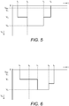
- Figure 5 shows an alternative analogue driving scheme.
- the pre-display period ends at time t 2 and the display period starts at time t 2 .
- a single pre-display signal level exceeding the initiation threshold V T is applied to change the fluids from the inactive state to a first pre-display state. This initiates the display element.
- a first display signal level is applied, different from the pre-display signal level, to provide the first display state.
- a second display signal level is applied, to provide a second display state.
- the first and second display signal levels at least meet the minimum area voltage threshold V MA .
- a zero signal level is applied thereby ending the display period, but it is envisaged that further display signal levels which at least meet the minimum area voltage threshold V MA may be applied during the display period.
- Figure 6 shows a further alternative analogue driving scheme.
- the pre-display period ends at time t 2 and the display period starts at time t 2 .
- This embodiment is a special example since a single pre-display signal level V 7 is applied which corresponds with the signal level required for the initial display state in the display period. This avoids re-addressing the display element at time t 2 .
- the signal level V 8 is applied to provide the second display state.
- a further display state is provided, followed by a zero signal level at time t 5 .
- further display states may be provided after time t 5 .
- the applied voltage at least meets the minimum area voltage threshold V MA .
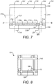
- Figures 7 and 8 show schematically an alternative display element for implementing the present invention.
- Figure 8 shows a cross section of the element shown in Figure 7 , taken along line A---B.
- a second electrode 18 is indicated with a dashed line, its extent representing the minimum area MA.
- Features are similar to those described previously with reference to Figure 1 and are labelled with the same reference numerals incremented by 700; corresponding descriptions should be taken to apply here also.
- the display element 701 comprises a second electrode 18 for applying a voltage to the fluids 711, 712.
- the second electrode is a separate electrode from the first electrode 709 and is electrically insulated therefrom such that a voltage applied to the first electrode does not interfere with a voltage applied to the second electrode, and vice versa.
- the second electrode 18 is arranged on the second support plate 706, and is separated from the fluids by an insulator, in this example the hydrophobic layer 113.
- the first electrode 709 has an extent less than the surface area SA of the hydrophobic layer 713.
- the second electrode 18 has an extent corresponding with the minimum area MA of the hydrophobic layer 713, as illustrated. Whilst the second electrode is shown in this embodiment as square in form, it is to be appreciated that other forms are possible, for example triangular or quarter circular.
- the second electrode may be positioned other than in the corner of the surface area SA. For example, the second electrode may be positioned in the centre of the surface area SA, or along at least part of a wall 716.
- the form of the first electrode may be adapted appropriately to tessellate with the second electrode as closely as possible, whilst maintaining sufficient insulation therebetween to provide for smooth movement of the fluids across the hydrophobic surface 113.
- the second electrode 18 is supplied with voltage signals by a signal line 20 connected to the display driving system via printed wiring on the support plate.
- the control system is arranged to apply during the pre-display period the at least one pre-display signal level to the second electrode 18, and during the display period the at least one display signal level to the first electrode 709. Throughout at least part of the display period the control system may apply a non-zero signal level to the second electrode 18 such that the display element is initiated throughout the display period.
- the non-zero signal should equal or exceed the minimum area voltage threshold V MA , once the display element has been initiated by first applying to the second electrode a voltage meeting or exceeding the initiation voltage threshold V T ; in this way the non-zero signal level is configured so the first and second fluids adjoin the surface throughout the display period, the second fluid adjoining at least the minimum area MA. If after initiation the signal level applied to the first electrode 709 exceeds the minimum area voltage threshold V MA , a signal level below the minimum area voltage threshold V MA , for example a zero signal level, may be applied to the second electrode 18 since the display signal level on the first electrode maintains the initiation.
- the display element may be arranged to reduce passage of radiation through the minimum area MA.
- a layer adjacent the minimum area MA may be provided for absorbing radiation, preferably all wavelengths, or at least those in the visible spectrum.
- the absorbing layer may be the second electrode 18, by forming the second electrode 18 from a material with a preferably high radiation absorbance. Further details are incorporated herein by way of reference to PCT application no. PCT/EP2009/057885 .
- the display element is arranged to reduce the passage of light through the minimum area MA
- the voltage change required to switch between two different greyscale display states is larger than the voltage change for switching between the same two greyscale display states of a display element arranged to give no reduction in the passage of light through the minimum area MA.
- the gradient of the curve for greyscale display states is shallower for a display element arranged to reduce the passage of light through the minimum area MA compared with a steeper curve gradient for the same greyscale display states of the electro-optic curve of a display element arranged to give no reduction in light passing through the minimum area MA.
- a further advantage is that for such embodiments of a display element arranged to reduce light passing through the minimum area MA the wider voltage range means that when a certain voltage is applied to multiple display elements of the display device the grey levels of the display elements are less sensitive to non-uniformities in pixel parameters such as oil volume, dielectric thickness or pixel wall height, than the grey levels of display elements arranged to give no reduction of light through the minimum area MA.
- the latter display elements have a steeper electro-optic curve and are therefore more sensitive to non-uniformities in pixel parameters.
- the minimum area MA may be located at a part of the surface which is outside of a display area of the surface for providing display effects, to improve the contrast-ratio.
- the electrode corresponding with the minimum area MA can be made of a transparent material, such as ITO, to create an effective black mask as no light is reflected to the viewer.
- a display device may use colour filters for imparting colour in radiation passing through the display.
- the display may comprise at least one group of four display elements: one display element for providing white light and the other three arranged with a colour filter for providing a different one of red, green and blue primary light colours.
- the group forms a full colour display pixel, with the white element being for controlling brightness, and providing a greater maximum brightness.
- the method of the invention may be applied to the red, green and blue display elements, so they remain initiated during the display period. However, the invention method may not be applied for the white display element.
- the white element may provide a display state with only the first fluid adjoining the surface during the display period.
- a display pixel may provide darker display states, including a darker black state, than if all elements in the group were driven according to the invention.
- rendering and/or addressing algorithms well known in the art for example dithering techniques, may be applied to the white element to compensate for hysteresis effects.
- the electrowetting display device comprises a plurality of display elements, and the control system may be arranged to apply the method of the present invention to more than one, and in some embodiments, all display elements.
- the first electrodes of at least two of the display elements being electrically connected to the control system, for example via the matrix .
- the first electrodes of each display element may be electrically connected via the matrix to the control system and, separately, the second electrodes may be electrically connected via a separate matrix to the control system, allowing for independent control of the first and second sets of electrodes.
- the second electrodes of a group of display elements may be bussed together, for example as a row, so the group may be initiated simultaneously by a single driver or a single output of a driver.
- the display device including the control system, may be arranged to initiate display elements of the display device individually, or to initiate a plurality of display elements, for example at least one line (a row or a column) of display elements (which may be synchronous with line scanning of the display), a group of display elements, and/or all of the display elements of the display device (which advantageously does not require line scanning).
- the control system may initiate simultaneously more than one display element, for example all of the display elements of the display device simultaneously.
- Such an initiation of all elements may be performed when power for the display device is switched on, so that all display elements are then ready for the display period. Their initiation can then be maintained throughout the display period.
- the display device comprises at least one test structure, the display device being arranged to initiate at least one display element using the at least one test structure.
- At least one test structure may be provided at the edge of a display device of a matrix of display elements, for testing the device for correct operation using at least one test signal.
- the test structure may be arranged to test all display elements of the device, and/or all odd and/or evenly numbered lines. Accordingly, initiation of the display elements may be provided using the test structures, to initiate all display elements, or odd and/or even lines of display elements simultaneously.
- embodiments of the present invention may include a memory store for storing data indicative of the display states provided on each display element.
- the display state history for each display element may therefore be logged.
- the control system can for example identify any display element(s) in an inactive state, and initiate that display element(s) ready for providing a display state.
- the front of screen effects caused by initiation could be limited by applying two short pre-display pulses of for example 5 volts to all display elements, compared with a single pre-display pulse of 5 volts of longer duration. In one example, these short pre-display pulses would each be 1 milli second long, or less.
- pre-display signal levels are set as low as possible, whilst meeting the initiation threshold V T , to reduce power consumption. Further, a scheme of pre-display signal levels with a minimum number of addressing actions may be advantageous, to avoid complex schemes requiring rapid re-addressing of the display elements and therefore higher frame rates.
- each display element may be subjected to a repeating sequence of a pre-display period followed by a display period, which may not align in time with each other for each display element; i.e. one display element may exist in the pre-display period whilst another element exists in the display period.
- each display element may be initiated at the start of each frame.
- a voltage is applied between the first electrode, in some embodiments also the second electrode, and the electrode in contact with the second fluid.
- the voltage may be applied between the first electrode, in certain embodiments also the second electrode, and a common electrode of the display device other than the second fluid contacting electrode.
Landscapes
- Engineering & Computer Science (AREA)
- Physics & Mathematics (AREA)
- Computer Hardware Design (AREA)
- General Physics & Mathematics (AREA)
- Theoretical Computer Science (AREA)
- Electrochromic Elements, Electrophoresis, Or Variable Reflection Or Absorption Elements (AREA)
- Control Of Indicators Other Than Cathode Ray Tubes (AREA)
Claims (15)
- Verfahren zum Ansteuern einer Elektrobenässungsanzeigeeinrichtung (1, 701), einschließlich eines Anzeigeelements (2, 702), wobei das Anzeigeelement (2, 702) Folgendes umfasst:einen Hohlraum;ein erstes Fluid (12, 712) und ein zweites Fluid (11, 711) in dem Hohlraum, wobei das erste Fluid (12, 712) mit dem zweiten Fluid (11, 711) mischbar ist;eine dem Hohlraum zugewandte Oberfläche; undeine erste Elektrode (9, 709),wobei das erste Fluid (12, 712), jedoch nicht das zweite Fluid (11, 711), in einem inaktiven Zustand an die Oberfläche angrenzt, wenn eine Nullspannung an das Anzeigeelement (2, 702) angelegt wird, unddas erste Fluid (12, 712) und das zweite Fluid (11, 711) in einem aktiven Zustand an die Oberfläche angrenzen, wenn eine von Null verschiedene Spannung an das Anzeigeelement (2, 702) angelegt wird,wobei die Elektrobenässungsanzeigeeinrichtung (1, 701) ein Steuersystem zum Anlegen einer Spannung an die erste Elektrode (9, 709) umfasst, um einen Anzeigezustand als Reaktion auf einen Signalpegel der Spannung bereitzustellen, wobei das Steuersystem für alle Anzeigezustände dazu ausgelegt ist, den Signalpegel während eines Anzeigezeitraums derart zu konfigurieren, dass das zweite Fluid (11, 711) an zumindest einen Mindestbereich der Oberfläche angrenzt, wobei der Mindestbereich größer als ein Nullbereich ist und wobei der Anzeigezeitraum ein Zeitraum ist, in dessen gesamtem Verlauf zumindest ein Anzeigezustand durch das Anzeigeelement (2, 702) bereitgestellt wird,wobei das Verfahren das Anlegen von zumindest einem Anzeigesignalpegel während des Anzeigezeitraums umfasst, wobei der zumindest eine Anzeigesignalpegel derart konfiguriert ist, dass das erste Fluid (12, 712) und das zweite Fluid (11, 711) während des gesamten Anzeigezeitraums an die Oberfläche angrenzen.
- Verfahren nach Anspruch 1, umfassend das Anlegen von zumindest einem Voranzeigesignalpegel vor dem Anzeigezeitraum, um das Anzeigeelement (2, 702) für den Anzeigezeitraum zu initiieren,
wobei der zumindest eine Voranzeigesignalpegel das Anzeigeelement (2, 702) gegebenenfalls durch Ändern des Anzeigeelements (2, 702) von dem inaktiven Zustand in den aktiven Zustand initiiert
und wobei der zumindest eine Voranzeigesignalpegel gegebenenfalls einen einzelnen Signalpegel oder einen einzelnen Signalimpuls umfasst. - Verfahren nach Anspruch 2, wobei der zumindest eine Voranzeigesignalpegel konfiguriert ist, um einen Signalpegel für einen Anfangsanzeigezustand in dem Anzeigezeitraum bereitzustellen.
- Verfahren nach Anspruch 2 oder 3, umfassend das Konfigurieren des zumindest einen Voranzeigesignalpegels, sodass das Initiieren des Anzeigeelements (2, 702) für den Anzeigezeitraum für einen Betrachter des Anzeigeelements (2, 702) nicht wahrnehmbar ist.
- Verfahren nach einem der vorhergehenden Ansprüche, umfassend das Steuern eines Zeitpunkts und/oder eines Signalpegels des zumindest einen Anzeigesignalpegels, sodass das erste Fluid (12, 712) und das zweite Fluid (11, 711) während des gesamten Anzeigezeitraums an die Oberfläche angrenzen.
- Verfahren nach einem der vorhergehenden Ansprüche, wobei der zumindest eine Anzeigesignalpegel derart konfiguriert ist, dass das zweite Fluid (11, 711) während des Anzeigezeitraums zumindest an 1 %, 5% oder 10 % der Oberfläche angrenzt.
- Verfahren nach einem der Ansprüche 2 bis 4, Anspruch 5, wenn abhängig von einem der Ansprüche 2 bis 4, oder 6, wenn abhängig von einem der Ansprüche 2 bis 4, wobei das Anzeigeelement (702) eine zweite Elektrode (18) umfasst, wobei das Verfahren das Anlegen des zumindest einen Voranzeigesignalpegels an die zweite Elektrode (18) vor dem Anzeigezeitraum und das Anlegen des zumindest einen Anzeigesignalpegels an die erste Elektrode (709) während des Anzeigezeitraums umfasst,
wobei das Verfahren gegebenenfalls das Anlegen eines von Null verschiedenen Signalpegels an die zweite Elektrode (18) während des gesamten Anzeigezeitraum umfasst
und wobei der von Null verschiedene Signalpegel gegebenenfalls derart konfiguriert ist, dass das erste Fluid (712) und das zweite Fluid (711) während des Anzeigezeitraums an die Oberfläche angrenzen. - Verfahren nach einem der vorhergehenden Ansprüche, wobei die angelegte Spannung eine Gleichspannung ist.
- Anzeigevorrichtung (1, 701), umfassend:ein Anzeigeelement (2, 702), umfassend:einen Hohlraum;ein erstes Fluid (12, 712) und ein zweites Fluid (11, 711) in dem Hohlraum, wobei das erste Fluid (12, 712) mit dem zweiten Fluid (11, 711) mischbar ist;eine dem Hohlraum zugewandte Oberfläche; undeine erste Elektrode (9, 709),wobei das erste Fluid (12, 712), jedoch nicht das zweite Fluid (11, 711), in einem inaktiven Zustand an die Oberfläche angrenzt, wenn eine Nullspannung an das Anzeigeelement (2, 702) angelegt wird, unddas erste Fluid (12, 712) und das zweite Fluid (11, 711) in einem aktiven Zustand an die Oberfläche angrenzen, wenn eine von Null verschiedene Spannung an das Anzeigeelement (2, 702) angelegt wird; undein Steuersystem zum Anlegen einer Spannung an die erste Elektrode (9, 709), um einen Anzeigezustand als Reaktion auf einen Signalpegel der Spannung bereitzustellen,wobei das Steuersystem für alle Anzeigezustände dazu ausgelegt ist, den Signalpegel während eines gesamten Anzeigezeitraum derart zu konfigurieren, dass das erste Fluid (12, 712) und das zweite Fluid (11, 711) während des gesamten Anzeigezeitraums an die Oberfläche angrenzen, wobei das zweite Fluid (11, 711) zumindest an einen Mindestbereich der Oberfläche angrenzt und wobei der Mindestbereich größer als ein Nullbereich ist und wobei der Anzeigezeitraum ein Zeitraum ist, in dessen gesamtem Verlauf zumindest ein Anzeigezustand durch das Anzeigeelement (2, 702) bereitgestellt wird.
- Anzeigevorrichtung (701) nach Anspruch 9, wobei das Anzeigeelement (702) eine zweite Elektrode (18) umfasst, wobei das Steuersystem dazu ausgelegt ist, zumindest einen Voranzeigesignalpegel anzulegen, um das Anzeigeelement (702) für den Anzeigezeitraum zu initiieren, wobei das Steuersystem dazu ausgelegt ist, den zumindest einen Voranzeigesignalpegel vor dem Anzeigezeitraum an die zweite Elektrode (18) anzulegen und den zumindest einen Anzeigesignalpegel während des Anzeigezeitraums an die erste Elektrode (709) anzulegen.
- Anzeigevorrichtung (701) nach Anspruch 9 oder 10, umfassend mehr als ein Anzeigeelement, wobei das mehr als eine Anzeigeelement jeweils das Anzeigeelement (702) umfasst, wobei die erste Elektrode (709) und/oder die zweite Elektrode (18) von jeweils zumindest zwei des mehr als einen Anzeigeelements elektrisch mit dem Steuersystem verbunden sind und das Steuersystem dazu ausgelegt ist, das mehr als eine Anzeigeelement gleichzeitig zu initiieren.
- Anzeigevorrichtung (701) nach Anspruch 10 oder Anspruch 11, wenn abhängig von Anspruch 10, umfassend eine Vielzahl von Anzeigeelementen, wobei die Vielzahl von Anzeigeelementen das Anzeigeelement (702) umfasst, wobei die zweite Elektrode (18) der Vielzahl von Anzeigeelementen jeweils mit dem Steuersystem verbunden ist, wobei das Steuersystem angeordnet ist, um die Vielzahl von Anzeigeelementen gleichzeitig zu initiieren, wobei die Vielzahl von Anzeigeelementen als eine Reihe von Anzeigeelementen der Anzeigevorrichtung (701) angeordnet ist oder wobei die Vielzahl von Anzeigeelementen die Gesamtheit der Anzeigeelemente der Anzeigevorrichtung (701) ist.
- Anzeigevorrichtung (1, 701) nach einem der Ansprüche 9 bis 12, wobei das Anzeigeelement (2, 702) dazu ausgelegt ist, den Durchgang von Strahlung durch einen Teil der Oberfläche zu reduzieren, an die das zweite Fluid (11, 711) nach der Initiierung des Anzeigeelements (2, 702) angrenzt.
- Anzeigevorrichtung (1, 701) nach einem der Ansprüche 9 bis 13, umfassend zumindest eine Testanordnung, wobei die Anzeigevorrichtung (1, 701) dazu ausgelegt ist, das Anzeigeelement (2, 702) unter Verwendung der zumindest einen Testanordnung zu initiieren.
- Anzeigevorrichtungssteuersystem zum Steuern eines Anzeigeelements (2, 702), wobei das Anzeigeelement (2, 702) Folgendes umfasst:einen Hohlraum;ein erstes Fluid (12, 712) und ein zweites Fluid (11, 711) in dem Hohlraum, wobei das erste Fluid (12, 712) mit dem zweiten Fluid (11, 711) mischbar ist;eine dem Hohlraum zugewandte Oberfläche; undeine erste Elektrode (9, 709),
wobei das erste Fluid (12, 712), jedoch nicht das zweite Fluid (11, 711), in einem inaktivenZustand an die Oberfläche angrenzt, wenn eine Nullspannung an das Anzeigeelement (2, 702) angelegt wird, unddas erste Fluid (12, 712) und das zweite Fluid (11, 711) in einem aktiven Zustand an die Oberfläche angrenzen, wenn eine von Null verschiedene Spannung an das Anzeigeelement (2, 702) angelegt wird;
wobei das Steuersystem dazu ausgelegt ist, eine Spannung an die erste Elektrode (9, 709) anzulegen, um einen Anzeigezustand als Reaktion auf einen Signalpegel der Spannung bereitzustellen,
wobei das Steuersystem für alle Anzeigezustände dazu ausgelegt ist, den Signalpegel während eines gesamten Anzeigezeitraum derart zu konfigurieren, dass das erste Fluid (12, 712) und das zweite Fluid (11, 711) während des gesamten Anzeigezeitraums an die Oberfläche angrenzen, wobei das zweite Fluid (11, 711) zumindest an einen Mindestbereich der Oberfläche angrenzt, wobei der Mindestbereich größer als ein Nullbereich ist und wobei der Anzeigezeitraum ein Zeitraum ist, in dessen gesamtem Verlauf zumindest ein Anzeigezustand durch das Anzeigeelement (2, 702) bereitgestellt wird.
Applications Claiming Priority (2)
| Application Number | Priority Date | Filing Date | Title |
|---|---|---|---|
| GBGB0918959.8A GB0918959D0 (en) | 2009-10-29 | 2009-10-29 | Driving an electrowetting display device |
| PCT/EP2010/066412 WO2011051413A1 (en) | 2009-10-29 | 2010-10-28 | Driving an electrowetting display device |
Publications (2)
| Publication Number | Publication Date |
|---|---|
| EP2494540A1 EP2494540A1 (de) | 2012-09-05 |
| EP2494540B1 true EP2494540B1 (de) | 2017-08-16 |
Family
ID=41434843
Family Applications (1)
| Application Number | Title | Priority Date | Filing Date |
|---|---|---|---|
| EP10782566.3A Active EP2494540B1 (de) | 2009-10-29 | 2010-10-28 | Ansteuerung einer elektrobenässungs-anzeigeeinrichtung mit reduzierung von hysteresis-effekten |
Country Status (8)
| Country | Link |
|---|---|
| US (2) | US9589513B2 (de) |
| EP (1) | EP2494540B1 (de) |
| JP (1) | JP5743340B2 (de) |
| KR (1) | KR101792289B1 (de) |
| CN (1) | CN102725787B (de) |
| GB (1) | GB0918959D0 (de) |
| TW (1) | TWI547715B (de) |
| WO (1) | WO2011051413A1 (de) |
Cited By (1)
| Publication number | Priority date | Publication date | Assignee | Title |
|---|---|---|---|---|
| US10991322B2 (en) | 2017-03-09 | 2021-04-27 | Academy Of Shenzhen Guohua Optoelectronics | Bistable driving method for electrowetting display and related electrowetting display |
Families Citing this family (20)
| Publication number | Priority date | Publication date | Assignee | Title |
|---|---|---|---|---|
| GB201010295D0 (en) | 2010-06-18 | 2010-08-04 | Liquavista Bv | Electrowetting display driving system |
| GB201114663D0 (en) | 2011-08-24 | 2011-10-12 | Samsung Lcd Nl R & D Ct Bv | Electrowetting display device |
| GB201117556D0 (en) | 2011-10-11 | 2011-11-23 | Samsung Lcd Nl R & D Ct Bv | Display apparatus |
| US9299295B2 (en) | 2013-12-20 | 2016-03-29 | Amazon Technologies, Inc. | Display driving method |
| CN106489176B (zh) * | 2013-12-20 | 2019-05-31 | 亚马逊科技公司 | 电润湿显示装置的驱动方法和显示控制器 |
| US9293089B2 (en) * | 2013-12-20 | 2016-03-22 | Amazon Technologies, Inc. | Display driving method |
| US9430972B2 (en) * | 2013-12-20 | 2016-08-30 | Amazon Technologies, Inc. | Electrowetting display device driving method |
| US9318060B2 (en) * | 2013-12-20 | 2016-04-19 | Amazon Technologies, Inc. | Display driving method |
| CN103984088B (zh) * | 2014-05-14 | 2016-09-28 | 华南师范大学 | 一种电润湿显示器及其驱动方法 |
| CN104867460A (zh) * | 2015-05-20 | 2015-08-26 | 华南师范大学 | 一种电润湿显示器灰度显示调制方法 |
| US10262601B1 (en) * | 2015-06-26 | 2019-04-16 | Amazon Technologies, Inc. | Electrowetting display device with ambient light detection |
| WO2017003939A1 (en) * | 2015-06-29 | 2017-01-05 | Amazon Technologies, Inc. | System and method for driving electrowetting display device |
| US9728143B2 (en) | 2015-06-29 | 2017-08-08 | Amazon Technologies, Inc. | System and method for driving electrowetting display device |
| CN106169287B (zh) * | 2016-08-03 | 2019-01-29 | 深圳市国华光电科技有限公司 | 一种电润湿多灰阶调节方法及电路 |
| CN106486071B (zh) * | 2016-12-23 | 2018-11-27 | 福州大学 | 一种电润湿显示器非线性电压幅度灰度调制方法及其装置 |
| US10504458B1 (en) | 2017-06-08 | 2019-12-10 | Amazon Technologies, Inc. | Electrowetting element with multiple electrodes |
| US10475401B1 (en) | 2017-06-08 | 2019-11-12 | Amazon Technologies, Inc. | Electrowetting element with multiple electrodes |
| US10546544B1 (en) | 2017-06-08 | 2020-01-28 | Amazon Technologies, Inc. | Electrowetting element with multiple electrodes |
| CN108806615B (zh) * | 2018-05-25 | 2020-09-01 | 福州大学 | 一种针对电润湿显示器的新型像素数据编码方法及装置 |
| CN110288954B (zh) * | 2019-07-26 | 2021-03-30 | 福州大学 | 一种低功耗多灰度电润湿显示器的驱动方法 |
Family Cites Families (18)
| Publication number | Priority date | Publication date | Assignee | Title |
|---|---|---|---|---|
| ATE548678T1 (de) | 2002-02-19 | 2012-03-15 | Samsung Lcd Nl R & D Ct Bv | Anzeigevorrichtung |
| US7359108B2 (en) * | 2003-01-27 | 2008-04-15 | Liquavista B.V. | Display device |
| US7180677B2 (en) * | 2003-01-31 | 2007-02-20 | Fuji Photo Film Co., Ltd. | Display device |
| WO2005036517A1 (en) | 2003-10-08 | 2005-04-21 | Koninklijke Philips Electronics N.V. | Electrowetting display device |
| FR2890875B1 (fr) * | 2005-09-22 | 2008-02-22 | Commissariat Energie Atomique | Fabrication d'un systeme diphasique liquide/liquide ou gaz en micro-fluidique |
| JP5065283B2 (ja) | 2005-11-15 | 2012-10-31 | サムスン エルシーディ ネザーランド アールアンドディ センター ビー ヴィ | エレクトロウェッティングディスプレイ用の駆動手段 |
| GB0611134D0 (en) | 2006-06-06 | 2006-07-19 | Liquavista Bv | Optical apparatus |
| US8115987B2 (en) * | 2007-02-01 | 2012-02-14 | Qualcomm Mems Technologies, Inc. | Modulating the intensity of light from an interferometric reflector |
| GB0706275D0 (en) | 2007-03-30 | 2007-05-09 | Liquavista Bv | Driving of electrowetting display device |
| US7903061B2 (en) * | 2007-05-31 | 2011-03-08 | Motorola, Inc. | Self illuminating electro wetting display |
| CN101681584B (zh) * | 2007-06-19 | 2013-01-02 | 夏普株式会社 | 显示元件以及使用该显示元件的电子设备 |
| GB0712859D0 (en) * | 2007-07-03 | 2007-08-08 | Liquavista Bv | Electrowetting system and method for operating it |
| JP2009204686A (ja) | 2008-02-26 | 2009-09-10 | Sony Corp | 光学絞り |
| JP2009204688A (ja) | 2008-02-26 | 2009-09-10 | Konica Minolta Business Technologies Inc | クリーニング装置及び画像形成装置 |
| GB0811811D0 (en) | 2008-06-27 | 2008-07-30 | Liquavista Bv | Electrowetting display device |
| EP2406783B1 (de) * | 2009-03-12 | 2016-02-10 | Creator Technology B.V. | Elektrofluidische anzeigevorrichtung |
| US8722432B2 (en) * | 2009-04-24 | 2014-05-13 | Arizona Board Of Regents, A Body Corporate Of The State Of Arizona, Acting For And On Behalf Of Arizona State University | Methods and system for on-chip decoder for array test |
| US8508468B2 (en) * | 2009-05-29 | 2013-08-13 | Creator Technology B.V. | Display apparatus comprising electrofluidic cells driven based on calculated charge corresponding to current and new pixel cell display properties |
-
2009
- 2009-10-29 GB GBGB0918959.8A patent/GB0918959D0/en not_active Ceased
-
2010
- 2010-10-28 EP EP10782566.3A patent/EP2494540B1/de active Active
- 2010-10-28 JP JP2012535839A patent/JP5743340B2/ja active Active
- 2010-10-28 WO PCT/EP2010/066412 patent/WO2011051413A1/en not_active Ceased
- 2010-10-28 KR KR1020127010996A patent/KR101792289B1/ko active Active
- 2010-10-28 CN CN201080049569.7A patent/CN102725787B/zh active Active
- 2010-10-29 TW TW099137315A patent/TWI547715B/zh active
-
2012
- 2012-04-26 US US13/456,416 patent/US9589513B2/en active Active
-
2017
- 2017-03-02 US US15/448,478 patent/US10056047B2/en active Active
Non-Patent Citations (1)
| Title |
|---|
| None * |
Cited By (1)
| Publication number | Priority date | Publication date | Assignee | Title |
|---|---|---|---|---|
| US10991322B2 (en) | 2017-03-09 | 2021-04-27 | Academy Of Shenzhen Guohua Optoelectronics | Bistable driving method for electrowetting display and related electrowetting display |
Also Published As
| Publication number | Publication date |
|---|---|
| WO2011051413A1 (en) | 2011-05-05 |
| TW201131200A (en) | 2011-09-16 |
| JP5743340B2 (ja) | 2015-07-01 |
| EP2494540A1 (de) | 2012-09-05 |
| KR20120105437A (ko) | 2012-09-25 |
| US10056047B2 (en) | 2018-08-21 |
| CN102725787B (zh) | 2016-01-13 |
| US9589513B2 (en) | 2017-03-07 |
| CN102725787A (zh) | 2012-10-10 |
| US20120256898A1 (en) | 2012-10-11 |
| GB0918959D0 (en) | 2009-12-16 |
| JP2013509605A (ja) | 2013-03-14 |
| US20170178575A1 (en) | 2017-06-22 |
| KR101792289B1 (ko) | 2017-10-31 |
| TWI547715B (zh) | 2016-09-01 |
Similar Documents
| Publication | Publication Date | Title |
|---|---|---|
| US9589513B2 (en) | Driving an electrowetting display device | |
| US8154486B2 (en) | Driving of electrowetting display device | |
| US8791891B2 (en) | Electrowetting system and method for operating | |
| JP5065283B2 (ja) | エレクトロウェッティングディスプレイ用の駆動手段 | |
| KR20060120006A (ko) | 전기습윤 디스플레이 디바이스 | |
| EP2795605B1 (de) | Ansteuerung einer elektrowetting-anzeigevorrichtung | |
| TW201033715A (en) | Multiple voltage level driving for electrophoretic displays | |
| EP3084750B1 (de) | Elektrowetting-anzeigevorrichtung und ansteuerungsverfahren | |
| KR20060079842A (ko) | 전기 영동 디스플레이 패널 | |
| WO2021252283A1 (en) | Electro-optic displays, and methods for driving same | |
| US9323044B2 (en) | Electrowetting display device | |
| US9299295B2 (en) | Display driving method | |
| KR20060133965A (ko) | 전기영동 디스플레이 패널 | |
| KR20060080869A (ko) | 전기영동 디스플레이 패널 | |
| US9293089B2 (en) | Display driving method | |
| US9430972B2 (en) | Electrowetting display device driving method | |
| US9318060B2 (en) | Display driving method |
Legal Events
| Date | Code | Title | Description |
|---|---|---|---|
| PUAI | Public reference made under article 153(3) epc to a published international application that has entered the european phase |
Free format text: ORIGINAL CODE: 0009012 |
|
| 17P | Request for examination filed |
Effective date: 20120529 |
|
| AK | Designated contracting states |
Kind code of ref document: A1 Designated state(s): AL AT BE BG CH CY CZ DE DK EE ES FI FR GB GR HR HU IE IS IT LI LT LU LV MC MK MT NL NO PL PT RO RS SE SI SK SM TR |
|
| DAX | Request for extension of the european patent (deleted) | ||
| RAP1 | Party data changed (applicant data changed or rights of an application transferred) |
Owner name: LIQUAVISTA B.V. |
|
| 17Q | First examination report despatched |
Effective date: 20160121 |
|
| RAP1 | Party data changed (applicant data changed or rights of an application transferred) |
Owner name: AMAZON EUROPE HOLDING TECHNOLOGIES SCS |
|
| GRAP | Despatch of communication of intention to grant a patent |
Free format text: ORIGINAL CODE: EPIDOSNIGR1 |
|
| INTG | Intention to grant announced |
Effective date: 20160822 |
|
| GRAJ | Information related to disapproval of communication of intention to grant by the applicant or resumption of examination proceedings by the epo deleted |
Free format text: ORIGINAL CODE: EPIDOSDIGR1 |
|
| INTC | Intention to grant announced (deleted) | ||
| GRAP | Despatch of communication of intention to grant a patent |
Free format text: ORIGINAL CODE: EPIDOSNIGR1 |
|
| INTG | Intention to grant announced |
Effective date: 20170310 |
|
| GRAS | Grant fee paid |
Free format text: ORIGINAL CODE: EPIDOSNIGR3 |
|
| GRAA | (expected) grant |
Free format text: ORIGINAL CODE: 0009210 |
|
| AK | Designated contracting states |
Kind code of ref document: B1 Designated state(s): AL AT BE BG CH CY CZ DE DK EE ES FI FR GB GR HR HU IE IS IT LI LT LU LV MC MK MT NL NO PL PT RO RS SE SI SK SM TR |
|
| REG | Reference to a national code |
Ref country code: GB Ref legal event code: FG4D |
|
| REG | Reference to a national code |
Ref country code: CH Ref legal event code: EP |
|
| REG | Reference to a national code |
Ref country code: IE Ref legal event code: FG4D |
|
| REG | Reference to a national code |
Ref country code: AT Ref legal event code: REF Ref document number: 919790 Country of ref document: AT Kind code of ref document: T Effective date: 20170915 |
|
| REG | Reference to a national code |
Ref country code: DE Ref legal event code: R096 Ref document number: 602010044473 Country of ref document: DE |
|
| REG | Reference to a national code |
Ref country code: DE Ref legal event code: R082 Ref document number: 602010044473 Country of ref document: DE Representative=s name: EISENFUEHR SPEISER PATENTANWAELTE RECHTSANWAEL, DE Ref country code: FR Ref legal event code: PLFP Year of fee payment: 8 |
|
| REG | Reference to a national code |
Ref country code: NL Ref legal event code: MP Effective date: 20170816 |
|
| REG | Reference to a national code |
Ref country code: LT Ref legal event code: MG4D |
|
| REG | Reference to a national code |
Ref country code: AT Ref legal event code: MK05 Ref document number: 919790 Country of ref document: AT Kind code of ref document: T Effective date: 20170816 |
|
| PG25 | Lapsed in a contracting state [announced via postgrant information from national office to epo] |
Ref country code: SE Free format text: LAPSE BECAUSE OF FAILURE TO SUBMIT A TRANSLATION OF THE DESCRIPTION OR TO PAY THE FEE WITHIN THE PRESCRIBED TIME-LIMIT Effective date: 20170816 Ref country code: LT Free format text: LAPSE BECAUSE OF FAILURE TO SUBMIT A TRANSLATION OF THE DESCRIPTION OR TO PAY THE FEE WITHIN THE PRESCRIBED TIME-LIMIT Effective date: 20170816 Ref country code: NO Free format text: LAPSE BECAUSE OF FAILURE TO SUBMIT A TRANSLATION OF THE DESCRIPTION OR TO PAY THE FEE WITHIN THE PRESCRIBED TIME-LIMIT Effective date: 20171116 Ref country code: FI Free format text: LAPSE BECAUSE OF FAILURE TO SUBMIT A TRANSLATION OF THE DESCRIPTION OR TO PAY THE FEE WITHIN THE PRESCRIBED TIME-LIMIT Effective date: 20170816 Ref country code: NL Free format text: LAPSE BECAUSE OF FAILURE TO SUBMIT A TRANSLATION OF THE DESCRIPTION OR TO PAY THE FEE WITHIN THE PRESCRIBED TIME-LIMIT Effective date: 20170816 Ref country code: AT Free format text: LAPSE BECAUSE OF FAILURE TO SUBMIT A TRANSLATION OF THE DESCRIPTION OR TO PAY THE FEE WITHIN THE PRESCRIBED TIME-LIMIT Effective date: 20170816 |
|
| PG25 | Lapsed in a contracting state [announced via postgrant information from national office to epo] |
Ref country code: RS Free format text: LAPSE BECAUSE OF FAILURE TO SUBMIT A TRANSLATION OF THE DESCRIPTION OR TO PAY THE FEE WITHIN THE PRESCRIBED TIME-LIMIT Effective date: 20170816 Ref country code: ES Free format text: LAPSE BECAUSE OF FAILURE TO SUBMIT A TRANSLATION OF THE DESCRIPTION OR TO PAY THE FEE WITHIN THE PRESCRIBED TIME-LIMIT Effective date: 20170816 Ref country code: IS Free format text: LAPSE BECAUSE OF FAILURE TO SUBMIT A TRANSLATION OF THE DESCRIPTION OR TO PAY THE FEE WITHIN THE PRESCRIBED TIME-LIMIT Effective date: 20171216 Ref country code: LV Free format text: LAPSE BECAUSE OF FAILURE TO SUBMIT A TRANSLATION OF THE DESCRIPTION OR TO PAY THE FEE WITHIN THE PRESCRIBED TIME-LIMIT Effective date: 20170816 Ref country code: BG Free format text: LAPSE BECAUSE OF FAILURE TO SUBMIT A TRANSLATION OF THE DESCRIPTION OR TO PAY THE FEE WITHIN THE PRESCRIBED TIME-LIMIT Effective date: 20171116 Ref country code: GR Free format text: LAPSE BECAUSE OF FAILURE TO SUBMIT A TRANSLATION OF THE DESCRIPTION OR TO PAY THE FEE WITHIN THE PRESCRIBED TIME-LIMIT Effective date: 20171117 Ref country code: PL Free format text: LAPSE BECAUSE OF FAILURE TO SUBMIT A TRANSLATION OF THE DESCRIPTION OR TO PAY THE FEE WITHIN THE PRESCRIBED TIME-LIMIT Effective date: 20170816 |
|
| PG25 | Lapsed in a contracting state [announced via postgrant information from national office to epo] |
Ref country code: DK Free format text: LAPSE BECAUSE OF FAILURE TO SUBMIT A TRANSLATION OF THE DESCRIPTION OR TO PAY THE FEE WITHIN THE PRESCRIBED TIME-LIMIT Effective date: 20170816 Ref country code: CZ Free format text: LAPSE BECAUSE OF FAILURE TO SUBMIT A TRANSLATION OF THE DESCRIPTION OR TO PAY THE FEE WITHIN THE PRESCRIBED TIME-LIMIT Effective date: 20170816 Ref country code: RO Free format text: LAPSE BECAUSE OF FAILURE TO SUBMIT A TRANSLATION OF THE DESCRIPTION OR TO PAY THE FEE WITHIN THE PRESCRIBED TIME-LIMIT Effective date: 20170816 |
|
| REG | Reference to a national code |
Ref country code: DE Ref legal event code: R097 Ref document number: 602010044473 Country of ref document: DE |
|
| PG25 | Lapsed in a contracting state [announced via postgrant information from national office to epo] |
Ref country code: SK Free format text: LAPSE BECAUSE OF FAILURE TO SUBMIT A TRANSLATION OF THE DESCRIPTION OR TO PAY THE FEE WITHIN THE PRESCRIBED TIME-LIMIT Effective date: 20170816 Ref country code: MC Free format text: LAPSE BECAUSE OF FAILURE TO SUBMIT A TRANSLATION OF THE DESCRIPTION OR TO PAY THE FEE WITHIN THE PRESCRIBED TIME-LIMIT Effective date: 20170816 Ref country code: SM Free format text: LAPSE BECAUSE OF FAILURE TO SUBMIT A TRANSLATION OF THE DESCRIPTION OR TO PAY THE FEE WITHIN THE PRESCRIBED TIME-LIMIT Effective date: 20170816 Ref country code: IT Free format text: LAPSE BECAUSE OF FAILURE TO SUBMIT A TRANSLATION OF THE DESCRIPTION OR TO PAY THE FEE WITHIN THE PRESCRIBED TIME-LIMIT Effective date: 20170816 Ref country code: EE Free format text: LAPSE BECAUSE OF FAILURE TO SUBMIT A TRANSLATION OF THE DESCRIPTION OR TO PAY THE FEE WITHIN THE PRESCRIBED TIME-LIMIT Effective date: 20170816 |
|
| REG | Reference to a national code |
Ref country code: CH Ref legal event code: PL |
|
| PLBE | No opposition filed within time limit |
Free format text: ORIGINAL CODE: 0009261 |
|
| STAA | Information on the status of an ep patent application or granted ep patent |
Free format text: STATUS: NO OPPOSITION FILED WITHIN TIME LIMIT |
|
| 26N | No opposition filed |
Effective date: 20180517 |
|
| REG | Reference to a national code |
Ref country code: IE Ref legal event code: MM4A |
|
| PG25 | Lapsed in a contracting state [announced via postgrant information from national office to epo] |
Ref country code: CH Free format text: LAPSE BECAUSE OF NON-PAYMENT OF DUE FEES Effective date: 20171031 Ref country code: LI Free format text: LAPSE BECAUSE OF NON-PAYMENT OF DUE FEES Effective date: 20171031 Ref country code: LU Free format text: LAPSE BECAUSE OF NON-PAYMENT OF DUE FEES Effective date: 20171028 |
|
| REG | Reference to a national code |
Ref country code: BE Ref legal event code: MM Effective date: 20171031 |
|
| PG25 | Lapsed in a contracting state [announced via postgrant information from national office to epo] |
Ref country code: SI Free format text: LAPSE BECAUSE OF FAILURE TO SUBMIT A TRANSLATION OF THE DESCRIPTION OR TO PAY THE FEE WITHIN THE PRESCRIBED TIME-LIMIT Effective date: 20170816 Ref country code: BE Free format text: LAPSE BECAUSE OF NON-PAYMENT OF DUE FEES Effective date: 20171031 |
|
| PG25 | Lapsed in a contracting state [announced via postgrant information from national office to epo] |
Ref country code: MT Free format text: LAPSE BECAUSE OF NON-PAYMENT OF DUE FEES Effective date: 20171028 |
|
| REG | Reference to a national code |
Ref country code: FR Ref legal event code: PLFP Year of fee payment: 9 |
|
| PG25 | Lapsed in a contracting state [announced via postgrant information from national office to epo] |
Ref country code: IE Free format text: LAPSE BECAUSE OF NON-PAYMENT OF DUE FEES Effective date: 20171028 |
|
| PG25 | Lapsed in a contracting state [announced via postgrant information from national office to epo] |
Ref country code: HU Free format text: LAPSE BECAUSE OF FAILURE TO SUBMIT A TRANSLATION OF THE DESCRIPTION OR TO PAY THE FEE WITHIN THE PRESCRIBED TIME-LIMIT; INVALID AB INITIO Effective date: 20101028 |
|
| PG25 | Lapsed in a contracting state [announced via postgrant information from national office to epo] |
Ref country code: CY Free format text: LAPSE BECAUSE OF NON-PAYMENT OF DUE FEES Effective date: 20170816 |
|
| PG25 | Lapsed in a contracting state [announced via postgrant information from national office to epo] |
Ref country code: MK Free format text: LAPSE BECAUSE OF FAILURE TO SUBMIT A TRANSLATION OF THE DESCRIPTION OR TO PAY THE FEE WITHIN THE PRESCRIBED TIME-LIMIT Effective date: 20170816 |
|
| PG25 | Lapsed in a contracting state [announced via postgrant information from national office to epo] |
Ref country code: TR Free format text: LAPSE BECAUSE OF FAILURE TO SUBMIT A TRANSLATION OF THE DESCRIPTION OR TO PAY THE FEE WITHIN THE PRESCRIBED TIME-LIMIT Effective date: 20170816 |
|
| PG25 | Lapsed in a contracting state [announced via postgrant information from national office to epo] |
Ref country code: PT Free format text: LAPSE BECAUSE OF FAILURE TO SUBMIT A TRANSLATION OF THE DESCRIPTION OR TO PAY THE FEE WITHIN THE PRESCRIBED TIME-LIMIT Effective date: 20170816 |
|
| PG25 | Lapsed in a contracting state [announced via postgrant information from national office to epo] |
Ref country code: HR Free format text: LAPSE BECAUSE OF FAILURE TO SUBMIT A TRANSLATION OF THE DESCRIPTION OR TO PAY THE FEE WITHIN THE PRESCRIBED TIME-LIMIT Effective date: 20170816 |
|
| PG25 | Lapsed in a contracting state [announced via postgrant information from national office to epo] |
Ref country code: AL Free format text: LAPSE BECAUSE OF FAILURE TO SUBMIT A TRANSLATION OF THE DESCRIPTION OR TO PAY THE FEE WITHIN THE PRESCRIBED TIME-LIMIT Effective date: 20170816 |
|
| P01 | Opt-out of the competence of the unified patent court (upc) registered |
Effective date: 20230523 |
|
| PGFP | Annual fee paid to national office [announced via postgrant information from national office to epo] |
Ref country code: DE Payment date: 20251029 Year of fee payment: 16 |
|
| PGFP | Annual fee paid to national office [announced via postgrant information from national office to epo] |
Ref country code: GB Payment date: 20251027 Year of fee payment: 16 |
|
| PGFP | Annual fee paid to national office [announced via postgrant information from national office to epo] |
Ref country code: FR Payment date: 20251027 Year of fee payment: 16 |