EP2494315B1 - Method and system for performance enhancement of resonant sensors - Google Patents
Method and system for performance enhancement of resonant sensors Download PDFInfo
- Publication number
- EP2494315B1 EP2494315B1 EP10827242.8A EP10827242A EP2494315B1 EP 2494315 B1 EP2494315 B1 EP 2494315B1 EP 10827242 A EP10827242 A EP 10827242A EP 2494315 B1 EP2494315 B1 EP 2494315B1
- Authority
- EP
- European Patent Office
- Prior art keywords
- sensor
- lcr
- assembly
- sensing
- antenna
- Prior art date
- Legal status (The legal status is an assumption and is not a legal conclusion. Google has not performed a legal analysis and makes no representation as to the accuracy of the status listed.)
- Not-in-force
Links
- 238000000034 method Methods 0.000 title claims description 15
- 239000000463 material Substances 0.000 claims description 28
- 238000005259 measurement Methods 0.000 claims description 26
- 239000002086 nanomaterial Substances 0.000 claims description 17
- 239000002245 particle Substances 0.000 claims description 16
- 239000000126 substance Substances 0.000 claims description 16
- 230000007613 environmental effect Effects 0.000 claims description 15
- 238000001453 impedance spectrum Methods 0.000 claims description 12
- 239000010410 layer Substances 0.000 claims description 11
- 239000002114 nanocomposite Substances 0.000 claims description 10
- 239000013078 crystal Substances 0.000 claims description 9
- 239000002105 nanoparticle Substances 0.000 claims description 9
- 238000000491 multivariate analysis Methods 0.000 claims description 8
- 229920000642 polymer Polymers 0.000 claims description 5
- 239000012620 biological material Substances 0.000 claims description 4
- 239000011258 core-shell material Substances 0.000 claims description 4
- 108090000765 processed proteins & peptides Proteins 0.000 claims description 4
- 230000004071 biological effect Effects 0.000 claims description 3
- 238000006073 displacement reaction Methods 0.000 claims description 3
- 239000011159 matrix material Substances 0.000 claims description 3
- 108091023037 Aptamer Proteins 0.000 claims description 2
- 108090000790 Enzymes Proteins 0.000 claims description 2
- 102000004190 Enzymes Human genes 0.000 claims description 2
- 241000700605 Viruses Species 0.000 claims description 2
- 150000004676 glycans Chemical class 0.000 claims description 2
- 229910010272 inorganic material Inorganic materials 0.000 claims description 2
- 239000011147 inorganic material Substances 0.000 claims description 2
- 239000011368 organic material Substances 0.000 claims description 2
- 238000006116 polymerization reaction Methods 0.000 claims description 2
- 229920001282 polysaccharide Polymers 0.000 claims description 2
- 239000005017 polysaccharide Substances 0.000 claims description 2
- 108090000623 proteins and genes Proteins 0.000 claims description 2
- 102000004169 proteins and genes Human genes 0.000 claims description 2
- 238000000935 solvent evaporation Methods 0.000 claims description 2
- 238000001338 self-assembly Methods 0.000 claims 1
- 230000004044 response Effects 0.000 description 51
- OKKJLVBELUTLKV-UHFFFAOYSA-N Methanol Chemical compound OC OKKJLVBELUTLKV-UHFFFAOYSA-N 0.000 description 30
- 239000011540 sensing material Substances 0.000 description 13
- YXFVVABEGXRONW-UHFFFAOYSA-N Toluene Chemical compound CC1=CC=CC=C1 YXFVVABEGXRONW-UHFFFAOYSA-N 0.000 description 12
- 230000008878 coupling Effects 0.000 description 12
- 238000010168 coupling process Methods 0.000 description 12
- 238000005859 coupling reaction Methods 0.000 description 12
- XLYOFNOQVPJJNP-UHFFFAOYSA-N water Substances O XLYOFNOQVPJJNP-UHFFFAOYSA-N 0.000 description 11
- 239000012491 analyte Substances 0.000 description 10
- -1 poly(vinyl alcohol) Polymers 0.000 description 9
- OKTJSMMVPCPJKN-UHFFFAOYSA-N Carbon Chemical compound [C] OKTJSMMVPCPJKN-UHFFFAOYSA-N 0.000 description 8
- LFQSCWFLJHTTHZ-UHFFFAOYSA-N Ethanol Chemical compound CCO LFQSCWFLJHTTHZ-UHFFFAOYSA-N 0.000 description 8
- 238000013459 approach Methods 0.000 description 8
- 230000008859 change Effects 0.000 description 8
- 238000001514 detection method Methods 0.000 description 8
- 230000006870 function Effects 0.000 description 8
- 239000000523 sample Substances 0.000 description 8
- 238000004458 analytical method Methods 0.000 description 7
- 230000000694 effects Effects 0.000 description 7
- VYPSYNLAJGMNEJ-UHFFFAOYSA-N Silicium dioxide Chemical compound O=[Si]=O VYPSYNLAJGMNEJ-UHFFFAOYSA-N 0.000 description 6
- GWEVSGVZZGPLCZ-UHFFFAOYSA-N Titan oxide Chemical compound O=[Ti]=O GWEVSGVZZGPLCZ-UHFFFAOYSA-N 0.000 description 6
- 239000002041 carbon nanotube Substances 0.000 description 6
- 229910021393 carbon nanotube Inorganic materials 0.000 description 6
- 239000002131 composite material Substances 0.000 description 6
- 239000004020 conductor Substances 0.000 description 6
- 230000035945 sensitivity Effects 0.000 description 6
- 230000003993 interaction Effects 0.000 description 5
- 229920006264 polyurethane film Polymers 0.000 description 5
- 239000000758 substrate Substances 0.000 description 5
- 239000004793 Polystyrene Substances 0.000 description 4
- 238000005452 bending Methods 0.000 description 4
- 229910044991 metal oxide Inorganic materials 0.000 description 4
- 150000004706 metal oxides Chemical class 0.000 description 4
- 239000002071 nanotube Substances 0.000 description 4
- 229920002223 polystyrene Polymers 0.000 description 4
- 230000035882 stress Effects 0.000 description 4
- 239000003990 capacitor Substances 0.000 description 3
- 238000000576 coating method Methods 0.000 description 3
- 238000011109 contamination Methods 0.000 description 3
- 238000010586 diagram Methods 0.000 description 3
- 230000005672 electromagnetic field Effects 0.000 description 3
- 239000000017 hydrogel Substances 0.000 description 3
- 230000001939 inductive effect Effects 0.000 description 3
- 239000002082 metal nanoparticle Substances 0.000 description 3
- 239000000203 mixture Substances 0.000 description 3
- 239000002159 nanocrystal Substances 0.000 description 3
- 239000002121 nanofiber Substances 0.000 description 3
- 229920003023 plastic Polymers 0.000 description 3
- 239000004033 plastic Substances 0.000 description 3
- 229920003229 poly(methyl methacrylate) Polymers 0.000 description 3
- 239000004926 polymethyl methacrylate Substances 0.000 description 3
- 239000000377 silicon dioxide Substances 0.000 description 3
- PMBXCGGQNSVESQ-UHFFFAOYSA-N 1-Hexanethiol Chemical compound CCCCCCS PMBXCGGQNSVESQ-UHFFFAOYSA-N 0.000 description 2
- QGZKDVFQNNGYKY-UHFFFAOYSA-N Ammonia Chemical compound N QGZKDVFQNNGYKY-UHFFFAOYSA-N 0.000 description 2
- 229920000557 Nafion® Polymers 0.000 description 2
- 229920002367 Polyisobutene Polymers 0.000 description 2
- PPBRXRYQALVLMV-UHFFFAOYSA-N Styrene Chemical compound C=CC1=CC=CC=C1 PPBRXRYQALVLMV-UHFFFAOYSA-N 0.000 description 2
- XLOMVQKBTHCTTD-UHFFFAOYSA-N Zinc monoxide Chemical compound [Zn]=O XLOMVQKBTHCTTD-UHFFFAOYSA-N 0.000 description 2
- 230000000712 assembly Effects 0.000 description 2
- 238000000429 assembly Methods 0.000 description 2
- 229920000547 conjugated polymer Polymers 0.000 description 2
- 239000000470 constituent Substances 0.000 description 2
- 229920001577 copolymer Polymers 0.000 description 2
- 230000007423 decrease Effects 0.000 description 2
- 230000001419 dependent effect Effects 0.000 description 2
- PCHJSUWPFVWCPO-UHFFFAOYSA-N gold Chemical compound [Au] PCHJSUWPFVWCPO-UHFFFAOYSA-N 0.000 description 2
- 229910052737 gold Inorganic materials 0.000 description 2
- 239000010931 gold Substances 0.000 description 2
- 230000006872 improvement Effects 0.000 description 2
- 239000002608 ionic liquid Substances 0.000 description 2
- 239000007788 liquid Substances 0.000 description 2
- 238000004519 manufacturing process Methods 0.000 description 2
- 239000002184 metal Substances 0.000 description 2
- 229910052751 metal Inorganic materials 0.000 description 2
- 239000002070 nanowire Substances 0.000 description 2
- 229920000767 polyaniline Polymers 0.000 description 2
- 238000000513 principal component analysis Methods 0.000 description 2
- 239000002096 quantum dot Substances 0.000 description 2
- 238000000611 regression analysis Methods 0.000 description 2
- 238000011160 research Methods 0.000 description 2
- 241000894007 species Species 0.000 description 2
- 238000001228 spectrum Methods 0.000 description 2
- 230000002277 temperature effect Effects 0.000 description 2
- XOLBLPGZBRYERU-UHFFFAOYSA-N tin dioxide Chemical compound O=[Sn]=O XOLBLPGZBRYERU-UHFFFAOYSA-N 0.000 description 2
- ULGGZAVAARQJCS-UHFFFAOYSA-N 11-sulfanylundecan-1-ol Chemical compound OCCCCCCCCCCCS ULGGZAVAARQJCS-UHFFFAOYSA-N 0.000 description 1
- YAJYJWXEWKRTPO-UHFFFAOYSA-N 2,3,3,4,4,5-hexamethylhexane-2-thiol Chemical compound CC(C)C(C)(C)C(C)(C)C(C)(C)S YAJYJWXEWKRTPO-UHFFFAOYSA-N 0.000 description 1
- UCJMHYXRQZYNNL-UHFFFAOYSA-N 2-Ethyl-1-hexanethiol Chemical compound CCCCC(CC)CS UCJMHYXRQZYNNL-UHFFFAOYSA-N 0.000 description 1
- FLFWJIBUZQARMD-UHFFFAOYSA-N 2-mercapto-1,3-benzoxazole Chemical compound C1=CC=C2OC(S)=NC2=C1 FLFWJIBUZQARMD-UHFFFAOYSA-N 0.000 description 1
- UYXGQGDQDFFSGE-UHFFFAOYSA-N 5-methoxy-2-methylbenzenethiol Chemical compound COC1=CC=C(C)C(S)=C1 UYXGQGDQDFFSGE-UHFFFAOYSA-N 0.000 description 1
- UGZAJZLUKVKCBM-UHFFFAOYSA-N 6-sulfanylhexan-1-ol Chemical compound OCCCCCCS UGZAJZLUKVKCBM-UHFFFAOYSA-N 0.000 description 1
- QTBSBXVTEAMEQO-UHFFFAOYSA-M Acetate Chemical compound CC([O-])=O QTBSBXVTEAMEQO-UHFFFAOYSA-M 0.000 description 1
- WHNWPMSKXPGLAX-UHFFFAOYSA-N N-Vinyl-2-pyrrolidone Chemical compound C=CN1CCCC1=O WHNWPMSKXPGLAX-UHFFFAOYSA-N 0.000 description 1
- XSTXAVWGXDQKEL-UHFFFAOYSA-N Trichloroethylene Chemical compound ClC=C(Cl)Cl XSTXAVWGXDQKEL-UHFFFAOYSA-N 0.000 description 1
- 230000004913 activation Effects 0.000 description 1
- 239000000853 adhesive Substances 0.000 description 1
- 230000001070 adhesive effect Effects 0.000 description 1
- 239000002998 adhesive polymer Substances 0.000 description 1
- 230000032683 aging Effects 0.000 description 1
- 239000000956 alloy Substances 0.000 description 1
- 229910045601 alloy Inorganic materials 0.000 description 1
- 229910021529 ammonia Inorganic materials 0.000 description 1
- 238000013528 artificial neural network Methods 0.000 description 1
- 229910002113 barium titanate Inorganic materials 0.000 description 1
- 230000008901 benefit Effects 0.000 description 1
- 239000008280 blood Substances 0.000 description 1
- 210000004369 blood Anatomy 0.000 description 1
- WQAQPCDUOCURKW-UHFFFAOYSA-N butanethiol Chemical compound CCCCS WQAQPCDUOCURKW-UHFFFAOYSA-N 0.000 description 1
- 238000004364 calculation method Methods 0.000 description 1
- 239000006229 carbon black Substances 0.000 description 1
- 239000002238 carbon nanotube film Substances 0.000 description 1
- 238000005119 centrifugation Methods 0.000 description 1
- 238000007621 cluster analysis Methods 0.000 description 1
- 238000004891 communication Methods 0.000 description 1
- 230000000295 complement effect Effects 0.000 description 1
- 238000012937 correction Methods 0.000 description 1
- 238000010219 correlation analysis Methods 0.000 description 1
- VTXVGVNLYGSIAR-UHFFFAOYSA-N decane-1-thiol Chemical compound CCCCCCCCCCS VTXVGVNLYGSIAR-UHFFFAOYSA-N 0.000 description 1
- 230000032798 delamination Effects 0.000 description 1
- 238000013461 design Methods 0.000 description 1
- 239000003989 dielectric material Substances 0.000 description 1
- WNAHIZMDSQCWRP-UHFFFAOYSA-N dodecane-1-thiol Chemical compound CCCCCCCCCCCCS WNAHIZMDSQCWRP-UHFFFAOYSA-N 0.000 description 1
- 230000005670 electromagnetic radiation Effects 0.000 description 1
- 238000005516 engineering process Methods 0.000 description 1
- 239000012530 fluid Substances 0.000 description 1
- 230000008014 freezing Effects 0.000 description 1
- 238000007710 freezing Methods 0.000 description 1
- 239000000499 gel Substances 0.000 description 1
- 229910021389 graphene Inorganic materials 0.000 description 1
- 229910001410 inorganic ion Inorganic materials 0.000 description 1
- MRELNEQAGSRDBK-UHFFFAOYSA-N lanthanum oxide Inorganic materials [O-2].[O-2].[O-2].[La+3].[La+3] MRELNEQAGSRDBK-UHFFFAOYSA-N 0.000 description 1
- 238000007477 logistic regression Methods 0.000 description 1
- 230000007246 mechanism Effects 0.000 description 1
- 150000002739 metals Chemical class 0.000 description 1
- 238000012544 monitoring process Methods 0.000 description 1
- 239000002073 nanorod Substances 0.000 description 1
- 230000003287 optical effect Effects 0.000 description 1
- KTUFCUMIWABKDW-UHFFFAOYSA-N oxo(oxolanthaniooxy)lanthanum Chemical compound O=[La]O[La]=O KTUFCUMIWABKDW-UHFFFAOYSA-N 0.000 description 1
- 230000000704 physical effect Effects 0.000 description 1
- 229920000191 poly(N-vinyl pyrrolidone) Polymers 0.000 description 1
- 229920001084 poly(chloroprene) Polymers 0.000 description 1
- 229920002755 poly(epichlorohydrin) Polymers 0.000 description 1
- 229920001390 poly(hydroxyalkylmethacrylate) Polymers 0.000 description 1
- 229920002401 polyacrylamide Polymers 0.000 description 1
- 229920000515 polycarbonate Polymers 0.000 description 1
- 239000004417 polycarbonate Substances 0.000 description 1
- 229920002338 polyhydroxyethylmethacrylate Polymers 0.000 description 1
- 229920002635 polyurethane Polymers 0.000 description 1
- 239000004814 polyurethane Substances 0.000 description 1
- 229920002451 polyvinyl alcohol Polymers 0.000 description 1
- 229920002102 polyvinyl toluene Polymers 0.000 description 1
- 230000008569 process Effects 0.000 description 1
- 102000004196 processed proteins & peptides Human genes 0.000 description 1
- 238000012545 processing Methods 0.000 description 1
- 239000011241 protective layer Substances 0.000 description 1
- 238000011084 recovery Methods 0.000 description 1
- 239000004065 semiconductor Substances 0.000 description 1
- 238000000926 separation method Methods 0.000 description 1
- 238000004904 shortening Methods 0.000 description 1
- 239000013464 silicone adhesive Substances 0.000 description 1
- 229910052709 silver Inorganic materials 0.000 description 1
- 239000004332 silver Substances 0.000 description 1
- 239000007787 solid Substances 0.000 description 1
- 230000003595 spectral effect Effects 0.000 description 1
- 239000010935 stainless steel Substances 0.000 description 1
- 229910001220 stainless steel Inorganic materials 0.000 description 1
- 238000003860 storage Methods 0.000 description 1
- 229920003048 styrene butadiene rubber Polymers 0.000 description 1
- 230000003075 superhydrophobic effect Effects 0.000 description 1
- 238000012546 transfer Methods 0.000 description 1
- ZNOKGRXACCSDPY-UHFFFAOYSA-N tungsten(VI) oxide Inorganic materials O=[W](=O)=O ZNOKGRXACCSDPY-UHFFFAOYSA-N 0.000 description 1
- 125000000391 vinyl group Chemical group [H]C([*])=C([H])[H] 0.000 description 1
- 229920002554 vinyl polymer Polymers 0.000 description 1
Images


Classifications
-
- G—PHYSICS
- G01—MEASURING; TESTING
- G01D—MEASURING NOT SPECIALLY ADAPTED FOR A SPECIFIC VARIABLE; ARRANGEMENTS FOR MEASURING TWO OR MORE VARIABLES NOT COVERED IN A SINGLE OTHER SUBCLASS; TARIFF METERING APPARATUS; MEASURING OR TESTING NOT OTHERWISE PROVIDED FOR
- G01D21/00—Measuring or testing not otherwise provided for
Definitions
- the invention relates to radio-frequency identification (RFID) sensing devices, and more particularly to inductor-capacitor-resistor (LCR) sensing devices having enhanced selectivity and sensitivity.
- RFID radio-frequency identification
- LCR inductor-capacitor-resistor
- Selectivity of sensors is one of critical aspects in sensor performance and applications. Typically, lack of selectivity prevents the wide use of sensors in sensing chemical and biological species in liquids and air for industrial and other applications.
- Two known approaches to address this problem include (1) developing very selective sensing films and (2) combining individual diverse sensors into an array. Unfortunately, each approach suffers from its own limitations. Highly selective sensing films typically have relatively slow recovery times due to strong vapor-material interactions. Combining sensors into an array could have manufacturing challenges.
- Sensor response originates from changes in dielectric properties of the sensing film deposited onto a sensor. While RFID sensors can detect individual chemical and physical changes based on changes in dielectric properties, the selectivity of these sensors may be improved further if other modes of detection are identified.
- US2005/007230 describes a sensor which responds to a time varying magnetic field and a reader which can discern changes in the sensor's response frequency, resistance and amplitude.
- This invention provides a sensor assembly capable of simultaneously sensing two or more environmental parameters of a sample, as defined by the claims.
- One embodiment of the assembly comprises: an inductor-capacitor-resistor (LCR) resonator sensor and a pick up coil in operative association with the LCR resonator sensor.
- the LCR resonator sensor comprises an antenna having a sensing region, a sensing film deposited onto the sensing region, and an attachment point for mechanically attaching the LCR resonator sensor to the assembly. In operation, viscoelastic changes in the sensing film cause displacement of the antenna relative to the pick up coil.
- a method for measuring two or more environmental conditions of a sample comprises: providing an LCR assembly; transmitting an electromagnetic signal from the LCR resonator sensor; sensing the LCR resonator sensor signal with the pick-up coil; and reading the LCR resonator sensor signal using a reader/writer device coupled to the pick-up coil.
- a method of measuring two or more conditions of an environment comprises using an LCR assembly wherein the LCR resonator has a IC memory chip attached to the antenna.
- the method involves applying different input power levels to the IC memory chip, and measuring complex impedance spectrum of the sensing antenna at the different input power levels. Changes in the complex impedance spectrum at the different power levels relate to different physical or biological properties of the sample.
- Also provided is a method of correcting for at least one noise parameter of an LCR resonant sensor response comprising the steps of: providing an LCR assembly; measuring the complex impedance of the LCR resonator sensor upon exposure to an environmental condition; and correcting for the noise parameters using inputs of the LCR sensor.
- the invention is related to an LCR assembly for simultaneous sensing of two or more environmental parameters of a sample.
- an LCR assembly is comprised of an LCR sensor, which uses an LCR resonant circuit and a pick up coil.
- An LCR sensor with an IC memory chip may also be referred to as an RFID sensor.
- such stress may cause the cantilever to deflect as a function of a specific environmental condition such as an analyte concentration.
- a specific environmental condition such as an analyte concentration.
- other changes in the environment may result in changes in the dielectric properties of the sensing film while causing small or no changes in the bending of the cantilever.
- measuring changes in both dielectric properties and bending of the cantilever may allow for simultaneous sensing of two or more environmental parameters.
- the RFID sensor is an LCR sensor and is capable of responding as a cantilever as well as to changes in dielectric property.
- a change in dielectric property is measured by measuring the resonance response of the LCR sensor.
- the LCR sensor may be used for sensing one or more conditions of a sample. Conditions may comprise a physical condition, a biological condition, or a chemical condition and may include a quantitative response for a desired parameter.
- the senor may be employed to monitor magnitude of an environmental parameter of interest such as, but not limited to, conductivity measurement, pH level, temperature, blood relevant measurement, ionic measurement, non-ionic measurement, non-conductivity measurement, electromagnetic radiation level measurement, pressure, vapor concentration, biological material concentration, and other types of measurements that may be taken from a typical fluid (solution or gas).
- an environmental parameter of interest such as, but not limited to, conductivity measurement, pH level, temperature, blood relevant measurement, ionic measurement, non-ionic measurement, non-conductivity measurement, electromagnetic radiation level measurement, pressure, vapor concentration, biological material concentration, and other types of measurements that may be taken from a typical fluid (solution or gas).
- the sample may be a container such as a disposable container, bioreactor, a stainless steel container, a plastic container, a polymeric material container, or a pre-sterilized polymeric material container.
- the container may be of different size and shape, for example, micro fluidic channel, a Petri dish, a glove box, a hood, or a plastic bag.
- a sample can be also an open volume such as an indoor enclosure or an outdoor monitoring station. Several samples can constitute the whole volume of a container.
- the container may or may not have a predetermined shape.
- the container is a disposable bioprocess component.
- the bioprocess component include a disposable storage bag, a disposable container, a product transfer line, a filter, a connector, a valve, a pump, a bioreactor, a separation column, a mixer, or a centrifugation system.
- the disposable container or bag may be made of plastic.
- the disposable container may comprise ports for inserting the LCR resonant sensor and the pick-up coil.
- the sensor and the pick-up coil may be inserted in the container using the same port.
- the sensor and the pick-up coil may be inserted in the container using separate ports.
- the sensor may be used in conjunction with disposable bioprocess components to monitor the parameters inside the components during or after the operation.
- the LCR sensor functions by providing a sensor readout that relies on the coupling between the LCR sensor and a corresponding pick up coil.
- the coupling between the LCR sensor and the pick up coil changes as a function of stress applied by a sensing film to the LCR sensor configured as a cantilever.
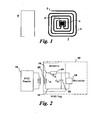
- FIG. 1 illustrates a typical configuration of an LCR sensor (1) and a pick-up coil (6).
- the LCR sensor may include an antenna (2), an IC memory chip (5), and a sensing film deposited onto at least a portion of the antenna (not shown).
- the ends on the antenna (3 and 4) are electrically connected using a conductor medium, such as a conductor wire, a conductor strip, or a conductor cable.
- the connection between the antenna and the conductor medium is such that the conductor medium does not electrically shorten the other regions of the antenna that it crosses.
- the IC memory chip 5 is used for storing information and may be activated by the radio frequency signal transmitted from a read/write unit (not shown).
- the antenna 2 of the sensor 1 receives and transmits signals.
- the pick-up coil 6 of the read/write unit which then sends the signals out of the sensing device, picks up the signals transmitted by the antenna 2.
- the sensor 1 and the pick-up coil 6 are placed in operative proximity.
- the sensor 1 and the pick-up coil 6 may be coupled via inductive coupling.
- the sensor 1 and the pick-up coil 6 may be adapted to communicate wirelessly.
- FIG. 2 is a schematic electrical diagram of an embodiment of the system of the invention showing an LCR sensor assembly. As shown the assembly comprises an LCR sensor, an IC memory chip, and a reader with its pick up coil.
- An LCR sensor which uses an LCR resonant circuit and an IC memory chip, may also be referred to as an RFID sensor.
- an IC memory chip is not required and an LCR sensor can also operate without the IC memory chip.
- an RFID tag 10 transmits data and energy with the help of magnetically coupled resonance circuit 12.
- a passive RFID tag does not need a battery for its function and includes a memory chip 14, which in FIG. 2 is referred to as a microchip.
- the memory chip 14 is connected to an antenna..
- the chip 14 is read by an RFID reader 18 by illuminating the antenna 16 tuned by a combination of an inductor 20 having an antenna inductance (L A ), a capacitor 22 having an antenna capacitance (C A ), and a resistor 24 having an antenna resistance (R A ).
- L A antenna inductance
- C A antenna capacitance
- R A resistor resistance
- the combination of an inductor of inductance L, a capacitor of capacitance C, and a resistor of resistance R is termed an LCR resonant circuit.
- tuning of the LCR sensor may be done during the fabrication of the LCR sensing antenna.
- an AC voltage is generated across the coil.
- This voltage is rectified in the chip 14 to result in a DC voltage for the chip operation.
- the chip 14 becomes functional when the DC voltage reaches a predetermined level needed to activate and operate the IC memory chip. This is also referred to as operational power level for the purpose of this application.
- operational power level for the purpose of this application.
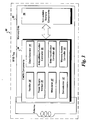
- FIG. 3 One embodiment of an LCR sensor configuration is illustrated in FIG. 3 and includes an RFID sensor 30 comprising an IC memory chip 32.
- the IC memory chip 32 is an IC device.
- the IC memory chip 32 includes RF signal modulation circuitry 34, fabricated using a complementary metal-oxide semiconductor (CMOS) process and non-volatile memory components 58.
- CMOS complementary metal-oxide semiconductor
- the CMOS chip 34 includes several sub-components, such as a rectifier 36, a power supply voltage controller 38, a modulator 40, a demodulator 42, a clock generator 44, an anti-collision function controller 46, a data input/output controller 48, and a memory access controller 50.
- Nonlimiting examples of memory are non-volatile memory types such as Electrically Erasable Programmable Read-Only Memory (EEPROM) and Ferroelectric Random Memory (FRAM).
- EEPROM Electrically Erasable Programmable Read-Only Memory
- FRAM Ferroelectric Random Memory
- an RFID interrogator reader/writer device
- An on-chip rectifier further converts this AC voltage into a DC voltage that activates the IC chip.
- the activated chip is capable of sending stored information back to the RFID interrogator and is capable of receiving new information to be stored into its memory.
- the RFID interrogator uses command pulses to communicate with the chip for reading and writing data.
- a comparator unit may be used to compare a current value of range of activation power levels with that of the predetermined range of power levels.
- a processing unit may also be employed to adjust one or more of a signal offset, a signal drift, a signal noise, and a slope of a sensor response.
- sensing response is provided from analyte-dependent change in circuit capacitance C, analyte-dependent change in circuit resistance R or a combination of the two.
- Analyte refers to the substance or condition being analyzed.
- the combination of changes in C and R is measured by measuring frequency response spectrum of the LCR resonant sensing circuit.
- LCR sensor response may be affected by both signal noise and signal drift. More specifically signal noise can be attributed to various environmental parameters such as ambient temperature, dielectric properties of the ambient environment, ambient humidity, proximity of the sensor to metals, surface contamination of sensor, and surface contamination of pick up coil. Signal drift can be attributed to a number of factors including surface contamination of the sensor or pick up coil, aging of the sensor components such as the sensing film, sensor substrate, antenna, and delamination of the sensing film from the substrate.
- an electromagnetic field is generated in the sensor antenna (65) upon reading and extends out from the plane of the sensor.
- the electromagnetic field can be affected by the dielectric property of an ambient environment providing the opportunity for measurements of physical parameters.
- the LCR sensor may be read wirelessly with a pickup coil or, in an alternative embodiment, by attaching a wire directly to a frequency spectrum measurement device such as a network analyzer.
- Measurements of conducting species can be performed using a protecting layer that separates the conducting medium from the LCR sensor antenna.
- a protective layer on the sensor antenna may be used to prevent electrical shortening and loss of the sensor resonance.
- Response of the LCR sensor to chemical or biological parameters involves changes in the dielectric and dimensional properties of sensing film deposited onto the resonant antenna of the LCR sensor. These changes are related to the analyzed environment that interacts with the sensing film (70).
- a sensing film (70) is selected for the proper chemical or biological recognition based on the analyte and sensing material properties.
- the analyte-induced changes in the sensing film affect the complex impedance of the antenna circuit through the changes in material resistance and capacitance between the antenna turns. Such changes provide diversity is response of an individual RFID sensor and provide the opportunity to replace a whole array of conventional sensors with a single LCR or RFID sensor.
- LCR resonant circuit parameters include impedance spectrum, real part of the impedance spectrum, imaginary part of the impedance spectrum, both real and imaginary parts of the impedance spectrum, frequency of the maximum of the real part of the complex impedance (Fp), magnitude of the real part of the complex impedance (Z p ), resonant frequency (F 1 ) and its magnitude (Z 1 ) of the imaginary part of the complex impedance, and anti-resonant frequency (F 2 ) and its magnitude (Z 2 ) of the imaginary part of the complex impedance.
- LCR resonant circuit parameters include parameters that can be extracted from the response of the equivalent circuit of the LCR sensor. These additional parameters may include quality factor of resonance, zero-reactance frequency, phase angle, and magnitude of impedance of the resonance circuit response of the LCR sensor.
- Applied multivariate analysis reduces the dimensionality of the multi-variable LCR sensor response to a single data point in multidimensional space for selective quantitation of different environmental parameters of interest.
- multivariate analysis tools are canonical correlation analysis, regression analysis, nonlinear regression analysis, principal components analysis, discriminate function analysis, multidimensional scaling, linear discriminate analysis, logistic regression, and/or neural network analysis.
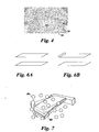
- FIG. 6A illustrates a known approach for measurements of LCR sensor response where a sensor is positioned at a certain distance from a pick up coil.
- FIG. 6B illustrates one embodiment of the invention, where the LCR sensor also serves as a cantilever and the LCR sensor signal is measured with a pick up coil.
- a resonant sensor is fabricated wherein an antenna is in conjunction with the sensing film or is embedded in a sensing film. The combination of the sensing film and the antenna provides a flexible substrate with a spring constant in the range from 0.001 to 100 N/m.
- the sensing film may be deposited onto the sensor and perform the function of predictably and reproducibly affecting the sensor response upon interaction with the environment.
- the typical sensor material may include a polymeric, organic, inorganic, biological, composite, or nanocomposite film that changes its property depending on the environment that it is placed in. Additional examples of sensing materials include ionic liquids with organic and inorganic ions, semiconducting nanocrystals, nanotubes, and nanofibers. Examples of properties of a sensing material that are predictably changing upon exposure to the environment include, but are not limited to, changes in capacitance, changes in resistance, changes in thickness, changes in viscoelasticity, or a combination thereof.
- capacitance change of a sensing film may be observed when a sensing film is a polyurethane film, is part of the capacitor structure of the LCR resonant sensor, and is exposed to different vapors.
- polyurethane film has a dielectric constant of 4.8 in air.
- toluene having a dielectric constant of 2.36
- the dielectric constant of polyurethane film decreases.
- the dielectric constant of polyurethane film increases.
- sensing films may show an observable change in resistance when exposed to chemical vapors.
- a sensing film is a polyaniline film
- its exposure to ammonia causes resistance of the polyaniline film to increase.
- This change in film resistance results in changes in impedance magnitude Z p , Z 1 , and Z 2 .
- a sensing film may be used in certain embodiments to measure changes in environmental parameters.
- a sensing film is a hydrogel
- the thickness of the film will change upon exposure to water.
- a sensing film comprising a hydrogel may include poly(hydroxyalkyl methacrylate), polyacrylamide, polymethacrylamide, poly (N-vinyl-2-pyrrolidone), and poly(vinyl alcohol).
- changes in viscoelasticity of a sensing film may also be used. Changes in viscoelasticity may be observed when a sensing film, such as is polyisobutylene, acrylonitrile-butadiene copolymer, polychloroprene, and polyepichlorohydrin are exposed to different vapors.
- a sensing film such as is polyisobutylene, acrylonitrile-butadiene copolymer, polychloroprene, and polyepichlorohydrin are exposed to different vapors.
- the sensing films may be comprised of a variety of materials provided the environmental changes are detectable by changes in the cantilever movement of the sensor or through changes in resonant LCR circuit parameters.
- Non-limiting examples of possible sensing film materials are a hydrogel such as poly(2-hydroxyethyl methacrylate), a sulfonated polymer such as Nafion, an adhesive polymer such as silicone adhesive, an inorganic film such as sol-gel film, a biological-containing film such as DNA, antibody, peptide or other biomolecules deposited as a film, a biological-containing film such as DNA, antibody, enzyme, peptide, polysaccharide, protein, aptamer, or other biomolecules or viruses, spores, cells, deposited as a part of a inorganic or polymeric film, a composite film, a nanocomposite film, functionalized carbon nanotube film, film comprised of surface functionalized gold nanoparticles, electrospun polymeric, inorganic, and composite nanofibers,
- Composites are materials made from two or more constituent materials with significantly different physical or chemical properties, which remain separate and distinct on a macroscopic level within the finished structure.
- Nonlimiting examples of composites include carbon black composites with poly(4-vinylphenol), poly(styrene-co-allyl alcohol), poly(vinyl chloride-covinyl acetate), and other materials.
- Nanocomposites are materials made from two or more constituent materials with significantly different physical or chemical properties, which remain separate and distinct on a nanoscale level within the finished structure.
- Nanocomposites include: carbon nanotube nanocomposites with polymers (such as poly(N-vinylpyrrolidone), polycarbonate, polystyrene, etc.); semiconducting nanocrystals quantum dots nanocomposites with polymers, metal oxide nanowires, and carbon nanotubes; metal nanoparticles or nanoclusters functionalized with carbon nanotubes.
- polymers such as poly(N-vinylpyrrolidone), polycarbonate, polystyrene, etc.
- semiconducting nanocrystals quantum dots nanocomposites with polymers, metal oxide nanowires, and carbon nanotubes metal nanoparticles or nanoclusters functionalized with carbon nanotubes.
- Further types of materials include aligned nanostructures where alignment is performed by various known methods (dielectrophoretic alignment, alignment during material polymerization, alignment due to spatial confinement, alignment during slow solvent evaporation, and others), self-assembled structures such as colloidal crystal structures of the same size of particles, multilayers of colloidal crystal films where different layers have different size of assembled particles, nanoparticle assemblies where the particles have core-shell structure with the particle core of one dielectric property and particle shell of another dielectric property, bio-inspired materials, zero-dimensional nanomaterials, one-dimensional nanomaterials, two-dimensional nanomaterials, and three-dimensional nanomaterials.
- Self-assembled structures include colloidal crystal structures of the same size of particles, multilayers of colloidal crystal films where different layers have different size of assembled particles, nanoparticle assemblies where the particles have core-shell structure with the particle core of one dielectric property and particle shell of another dielectric property.
- materials of self-assembled colloidal crystal structures include polystyrene, polymethylmethacrylate, polyvinyltoluene, styrene/butadiene copolymers, styrene/vinyltoluene copolymers, and silica.
- the typical diameters of these colloidal particles depend on type of material and may range from 50 nanometers to 25 micrometers.
- Nonlimiting examples of colloidal crystal structures with multiple layers include at least one layer of particles of one size assembled as a colloidal array onto the sensor substrate and at least one layer of particles of another size assembled as a colloidal array on top of the previous layer.
- Nonlimiting examples of bio-inspired materials include super hydrophobic or superhydrophilic coatings.
- Nonlimiting examples of zero-dimensional nanomaterials include metal nanoparticles, semiconducting nanocrystals.
- Nonlimiting examples of one-dimensional nanomaterials include nanotubes, nanowires, nanorods, and nanofibers.
- Nonlimiting examples of two-dimensional nanomaterials include graphene.
- Nonlimiting examples of three-dimensional nanomaterials include colloidal spheres.
- Nonlimiting examples of nanoparticles that have core-shell structure with the particle core of one dielectric property and particle shell of another dielectric property include: metal (gold, silver, their alloy, etc.) core nanoparticles and organic shell layers of dodecanethiol, decanethiol, 1-butanethiol, 2-ethylhexanethiol, hexanethiol, tert-dodecanethiol, 4-methoxy-toluenethiol, 2-mercaptobenzoxazole, 11-mercapto-1-undecanol, 6-hydroxyhexanethiol; polymeric core (polystyrene, polymethylmethacrylate) and inorganic shell (silica); isolating core (polystyrene, polymethylmethacrylate, silica) and semiconducting shell (carbon nanotubes, TiO2, ZnO, SnO2, WO3), and carbon nanotube core that is decorated with metal nanoparticles
- an LCR sensor is configured as a cantilever such that the antenna/ sensing film combination is mechanically attached to the assembly resulting in the sensing film having a cantilevered distal end opposite to a supported proximal end. Viscoelastic changes in the sensing film cause displacement of the sensing film relative to the supported proximal end.
- an antenna is deposited on to a dielectric material substrate such as a polymeric film.
- a sensing material is then deposited onto the antenna such that the electromagnetic field in the antenna probes the sensing film, as illustrated in FIG. 4 .
- the mechanical attachment of the antenna/sensing film may be a direct attachment to the assembly, as shown in FIG. 6 where the assembly contains is a pick up coil, or it may be through a mechanical support structure contained within the resonant sensor.
- the mechanical support structure may be an adhesive, an inorganic film layer or an organic film layer. In other embodiments additional points of attachment may be used in areas adjacent to the supported proximal end, provided the distal end of the sensing film is able to deflect.
- the sensing film deposited onto this resonant sensor deflects the sensor and the deflection is measured with a pick up coil.
- the pick up coil also measures dielectric changes of the sensing film from the measurement of the impedance of the sensor.
- the pick up coil measures sensor response using inductive coupling or capacitive coupling.
- the resonant LCR sensor operates in the range from 50 kHz to 30 GHz, more preferably from 70 kHz to 25 GHz, and more preferably from 100 kHz to 20 GHz. In certain embodiments, the resonant LCR sensor may operate at a specific frequency such as around 125 kHz, 134 kHz, 13.5 MHz, or 915 MHz, or 2.4 GHz.
- FIG. 7 shows a representative sensing mechanism where a mechanical sensor response (cantilever bending) is provided from the interactions of analyte (80) with the sensing film of the cantilever surface (90) as described in prior art by Hagleitner et al., Nature 2001, 414, 293-296 .
- a mechanical sensor response cantilever bending
- There are several approaches for measuring the interaction of analytes with a sensing film on a cantilever including, but not limited to, optical, frequency, piezoresistive, and capacitance readouts.
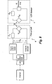
- the operation of an LCR sensor (1) relative to a pick up coil (6) is based on measurements and changes in inductive coupling between the two elements. Reading and writing of digital information into the LCR sensor 1 and measurement of complex impedance of the LCR sensor antenna are performed via mutual inductance coupling between the LCR sensor antenna and the pickup coil 6 coupled to a reader.
- the interaction between the LCR sensor and the pickup coil can be described using a general mutual inductance coupling circuit model.
- the model includes an intrinsic impedance of the pickup coil Z c and an intrinsic impedance of the LCR sensor Z s .
- the mutual inductance coupling M between the pickup coil and the LCR sensor is represented by two voltage sources V cs and V sc .
- the equation illustrates the importance of the control of the mutual inductance coupling M for the accurate reading of the LCR sensor response because the measured impedance Z T is proportional to the square of the mutual inductance coupling M.
- the LCR sensor when the LCR sensor is interrogated with a RFID reader/writer device to read the complex impedance, different power levels are applied to perform these measurements in order to control the sensitivity of the sensor and its selectivity.
- a voltage needs to be applied to activate the chip 34.
- an RFID interrogator reader/writer device
- An on-chip rectifier further converts this AC voltage into a DC voltage that activates the IC chip.
- the activated chip adds its electronic properties (including but not limited to its capacitance and resistance) to the antenna circuit.
- the antenna circuit experiences a resonance peak shift to smaller frequencies, peak magnitude decrease, and peak distortion.
- the multivariate sensor response provides a significantly orthogonal response to different environmental effects.
- this sensor property provides the ability of the sensor to correct for the temperature effects of sensor response.
- This temperature correction originates from the temperature-induced effects on the resistance and capacitance of the sensing film deposited onto the sensor antenna and the temperature induced effects on the resistance and capacitance of the sensor antenna itself.
- the resistance and capacitance of the sensing film is selected to be predictably variable as a function of analyte concentration.
- the temperature affects the sensing film and sensor antenna with different magnitude of the effects, because of the different materials properties of the antenna and sensing film. Since the sensor yields a multivariable response, temperature effects of the sensor antenna and the sensing material are separated.
- Nonlimiting examples of sensing materials that are affected by temperature fluctuations, which may be corrected by the multivariable sensor output include polymeric materials, organic materials, biological materials, and inorganic materials.
- the nonlimiting examples of temperature regions for operation of these sensing materials include temperatures below the freezing point of water 0°C, temperatures below 100°C, and temperatures over 100°C.
- Nonlimiting examples of sensing materials that work at temperatures below 0°C include siloxanes, polyisobutylene, and others. Nonlimiting examples of their uses at these temperatures are for vapor detection.
- Nonlimiting examples of sensing materials that work at temperatures below 100°C include conjugated polymers, carbon nanotubes, titania nanotubes, carbon nanotubes functionalized with conjugated polymers or biological molecules such as DNA, peptides, and others.
- Nonlimiting examples of their uses at these temperatures are for gas and biological detection in air and water.
- Nonlimiting examples of sensing materials that work at temperatures above 100°C include metal oxides, and semiconducting metal oxides, mixed-oxides, titania nanotubes, ionic liquids, and quantum dots.
- Nonlimiting examples of their uses at these temperatures are for gas detection.
- sensing materials operating above 100°C also include, but are not limited to, those that have combination of permittivity capacitance and conductivity effects or preferentially capacitance or preferentially conductivity effects.
- a mixed-oxide composition of BaTiO 3 and La 2 O3 (1:1 mole ratio) has variable conductivity upon exposure to CO 2 .
- a mixed-oxide composition of ZnO and WO 3 (1:1 mole ratio) has variable permittivity upon exposure to NO. Permittivity changes of the sensing film are detected by the pronounced changes in sensor capacitance.
- Passive LCR sensors were used for demonstration of the disclosed sensing method and system; a passive LCR sensor is defined as a sensor, which is battery free.
- a passive LCR sensor is defined as a sensor, which is battery free.
- three vapors were employed trichloroethylene (TCE), methanol (MeOH), and toluene (TOL).
- Vapors detection was performed using a polyurethane (Thermedics Co., Boston, MA) film as the sensing film.
- Polymeric sensing film was applied onto the resonant LCR antenna by a conventional draw-coating process.
- Measurements of the complex impedance of LCR sensors were performed with a network analyzer (Model E5062A, Agilent Technologies, Inc. Santa Clara, CA) under computer control.
- the network analyzer was used to scan the frequencies over the range of interest and to collect the complex impedance response from the LCR sensors. For gas sensing, generation of different concentrations of vapors was done using an in-house built computer-controlled vapor-generation system. Collected complex impedance data was analyzed using KaleidaGraph (Synergy Software, Reading, PA) and PLS_Toolbox (Eigenvector Research, Inc., Manson, WA) operated with Matlab (The Mathworks Inc., Natick, MA).
- the selectivity of LCR sensors was evaluated using principal components analysis (PCA).
- PCA principal components analysis
- the amount of variance in data captured by individual principal components (PCs) was indicative of sensor selectivity.
- selectivity descriptors can be determined for measured vapors.
- the selectivity descriptor was represented as a vector in PCA space. This vector was described by a unique combination of the respective scores of principal components.
- the selectivity descriptors from sensor responses to each vapor were considered as clusters in the PCA space. Each cluster S was represented by its mean and standard deviation with respect to k-th principal component.
- E ij ⁇ 1 n W k S k ⁇ i - S k ⁇ j 2 1 / 2
- i and j are indices of clusters S i and S j , respectively
- E ij is the Euclidean distance between these clusters
- W k is the weighting factor (equal to captured percent variance) of the k-th principal component
- n is the number of principal components used for multivariate analysis.
- FIG. 9 demonstrates an example of such determination of improvement of sensor selectivity.
- a PCA response of a sensor to three analytes and a blank is compared using a conventional LCR sensor readout ( FIG. 9A ) and a cantilever-based readout of this invention ( FIG. 9B ).
- the distance between the blank and vapors 1,2, and 3 quantifies the amount of sensor selectivity.
- the use of multivariate analysis on experimental data showed that the combined independent effects of resistance and capacitance contributions of the sensing film lead to the to the vapor-induced resonance response of the LCR sensor antenna circuit with high variance captured by PC1 and PC2.
- the magnitude of PC2 using a conventional readout of the LCR sensor was 10%.
- the magnitude of PC2 using a cantilever readout of the LCR sensor was 40%.
- Results of PCA analysis of LCR sensor response using a conventional readout and using cantilever-response sensor are compared in FIG. 10 .
- Passive LCR sensors were used for demonstration of the disclosed sensing method and system. As model analytes, three vapors were employed such as water, methanol (MeOH), and ethanol (EtOH). Vapors detection was performed using a Nafion polymer (Aldrich, Milwaukee, WI) film as the sensing film. Polymeric sensing film was applied onto the resonant LCR antenna by a conventional draw-coating process.
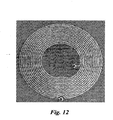
- the LCR sensor is shown in FIG. 12 and contains a MB89R118A memory chip (Fujitsu Corp., Japan) operating at a nominal frequency of 13.56 MHz. Measurements of the complex impedance of LCR sensor were performed with a network analyzer (Model 8751A, Hewlett Packard, Inc.
- the network analyzer was used to scan the frequencies over the range of interest and to collect the complex impedance response from the LCR sensors. For gas sensing, generation of different concentrations of vapors was done using an in-house built computer-controlled vapor-generation system. Collected complex impedance data was analyzed using KaleidaGraph (Synergy Software, Reading, PA) and PLS_Toolbox (Eigenvector Research, Inc., Manson, WA) operated with Matlab (The Mathworks Inc., Natick, MA).
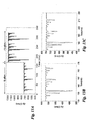
- FIG. 13 illustrates the Z p response of the sensor at two powers of +15 dBm and -15 dBm. This data illustrates that by varying the power, the sensitivity of the response was modified and the selectivity of the response was modified as well as summarized in Table 1.
- FIG. 14 illustrates F p response of LCR sensor at two interrogation powers of +15dBm and -15 dBm upon measurements of water, methanol, and ethanol vapors. Although not as pronounced as for Z p response, the selectivity and selectivity patterns of the Fp response have been modified upon sensor interrogation at two powers of +15dBm and -15 dBm. Table 1. Effects of interrogation power on the sensitivity and selectivity of the vapor response.
Landscapes
- Physics & Mathematics (AREA)
- General Physics & Mathematics (AREA)
- Investigating Or Analyzing Materials By The Use Of Electric Means (AREA)
- Testing Or Calibration Of Command Recording Devices (AREA)
- Investigating Or Analyzing Materials By The Use Of Magnetic Means (AREA)
Description
- The invention relates to radio-frequency identification (RFID) sensing devices, and more particularly to inductor-capacitor-resistor (LCR) sensing devices having enhanced selectivity and sensitivity.
- Selectivity of sensors is one of critical aspects in sensor performance and applications. Typically, lack of selectivity prevents the wide use of sensors in sensing chemical and biological species in liquids and air for industrial and other applications. Two known approaches to address this problem include (1) developing very selective sensing films and (2) combining individual diverse sensors into an array. Unfortunately, each approach suffers from its own limitations. Highly selective sensing films typically have relatively slow recovery times due to strong vapor-material interactions. Combining sensors into an array could have manufacturing challenges.
- Chemical and biological detection has been accomplished using RFID sensors. In this approach, ubiquitous and cost-effective passive RFID tags with integrated circuit read/write memory chips operating, for example at 13.56 MHz, may be adapted for chemical sensing. By applying a sensing film onto the resonant antenna of the RFID sensor and measuring the complex impedance of the RFID resonant antenna it is possible to correlate impedance response to chemical properties of interest. The digital data may also written into and read from the integrated circuit (IC) memory chip of the RFID sensor. This IC memory chip may store a unique digital ID, sensor calibrations, and information about the object onto which the sensor is attached.
- Sensor response originates from changes in dielectric properties of the sensing film deposited onto a sensor. While RFID sensors can detect individual chemical and physical changes based on changes in dielectric properties, the selectivity of these sensors may be improved further if other modes of detection are identified.
- Therefore, it would be desirable to provide sensor assembly with additional modes of sensing.
US2005/007230 describes a sensor which responds to a time varying magnetic field and a reader which can discern changes in the sensor's response frequency, resistance and amplitude. - This invention provides a sensor assembly capable of simultaneously sensing two or more environmental parameters of a sample, as defined by the claims.
- One embodiment of the assembly comprises: an inductor-capacitor-resistor (LCR) resonator sensor and a pick up coil in operative association with the LCR resonator sensor. The LCR resonator sensor comprises an antenna having a sensing region, a sensing film deposited onto the sensing region, and an attachment point for mechanically attaching the LCR resonator sensor to the assembly. In operation, viscoelastic changes in the sensing film cause displacement of the antenna relative to the pick up coil.
- In a second embodiment, a method for measuring two or more environmental conditions of a sample is provided. The method comprises: providing an LCR assembly; transmitting an electromagnetic signal from the LCR resonator sensor; sensing the LCR resonator sensor signal with the pick-up coil; and reading the LCR resonator sensor signal using a reader/writer device coupled to the pick-up coil.
- In a third embodiment a method of measuring two or more conditions of an environment comprises using an LCR assembly wherein the LCR resonator has a IC memory chip attached to the antenna. The method involves applying different input power levels to the IC memory chip, and measuring complex impedance spectrum of the sensing antenna at the different input power levels. Changes in the complex impedance spectrum at the different power levels relate to different physical or biological properties of the sample.
- Also provided is a method of correcting for at least one noise parameter of an LCR resonant sensor response comprising the steps of: providing an LCR assembly; measuring the complex impedance of the LCR resonator sensor upon exposure to an environmental condition; and correcting for the noise parameters using inputs of the LCR sensor.
- These and other features, aspects, and advantages of the present invention will become better understood when the following detailed description is read with reference to the accompanying drawings in which like characters represent like parts throughout the drawings.
-
FIG. 1 is a schematic representation of an LCR sensor having an IC memory chip, an antenna, and a pick up coil. -
FIG. 2 is a schematic electrical diagram of an embodiment of the system of the invention showing an LCR sensor, an IC memory chip and a reader with its pick up coil. -
FIG. 3 is a schematic diagram of an embodiment of the system of the invention showing of an RFID tag and an IC memory chip for use in an LCR sensor. -
FIG.4 is a non-limiting example of the operation of the disclosed sensor. -
FIG. 5 is an example of a measured complex impedance spectrum used for multivariate analysis. -
FIG. 6 is an illustration of methods used in measuring LCR sensor response: (A) known approach for measurements of LCR sensor response where a sensor is positioned at a certain distance from a pick up coil, and (B) non-limiting embodiment of the present invention, where the LCR sensor also serves as a cantilever and the LCR sensor signal is measured with a pick up coil. -
FIG. 7 is a depiction of the general principle of cantilever operations used for sensor detection (prior art). -
FIG. 8 shows the operation principle, which is applied in the operation of physical, chemical, and biological passive LCR sensors. -
FIG. 9 is an example demonstrating improvement in sensor selectivity. -
FIG. 10 shows the results of PCA analysis of LCR sensor response using a conventional readout compared to a cantilever-response sensor. -
FIG. 11 is an illustration of a single PCA plot that combines two types of readout from an LCR sensor. -
FIG. 12 illustrate one embodiment of an LCR sensor for selective chemical sensing with a MB89R118A memory chip (Fujitsu Corp., Japan) operating at a nominal frequency of 13.56 MHz. -
FIG. 13 illustrates Zp response of LCR sensor at two interrogation powers of + 15 dBm and -15 dBm upon measurements of water, methanol, and ethanol vapors. -
FIG. 14 illustrates Fp response of LCR sensor at two interrogation powers of + 15 dBm and -15 dBm upon measurements of water, methanol, and ethanol vapors. - The invention is related to an LCR assembly for simultaneous sensing of two or more environmental parameters of a sample. As used herein an LCR assembly is comprised of an LCR sensor, which uses an LCR resonant circuit and a pick up coil. An LCR sensor with an IC memory chip may also be referred to as an RFID sensor.
- Sensor response originating from the changes in dielectric properties of a sensing film deposited onto a RFID sensor is known. Such an approach is limited as it is applicability only to sensing films that change their dielectric properties. In contrast, enhanced selectivity may be achieved when the RFID configured to respond as a cantilever where viscoelastic changes of the sensing film result in the generation of the stress in the sensing film. The stress may result in the bending of the cantilever sensor in relation to a corresponding pick up coil. The resulting sensor selectivity may be measured and quantified using multivariate analysis (principal components analysis, PCA) as the increase of the contribution of the second principal component in sensor response.
- In certain embodiments, such stress may cause the cantilever to deflect as a function of a specific environmental condition such as an analyte concentration. At the same time, other changes in the environment may result in changes in the dielectric properties of the sensing film while causing small or no changes in the bending of the cantilever. Thus, measuring changes in both dielectric properties and bending of the cantilever may allow for simultaneous sensing of two or more environmental parameters.
- In certain embodiments the RFID sensor is an LCR sensor and is capable of responding as a cantilever as well as to changes in dielectric property. A change in dielectric property is measured by measuring the resonance response of the LCR sensor. As such, the LCR sensor may be used for sensing one or more conditions of a sample. Conditions may comprise a physical condition, a biological condition, or a chemical condition and may include a quantitative response for a desired parameter. For example, the sensor may be employed to monitor magnitude of an environmental parameter of interest such as, but not limited to, conductivity measurement, pH level, temperature, blood relevant measurement, ionic measurement, non-ionic measurement, non-conductivity measurement, electromagnetic radiation level measurement, pressure, vapor concentration, biological material concentration, and other types of measurements that may be taken from a typical fluid (solution or gas).
- In certain embodiments, the sample may be a container such as a disposable container, bioreactor, a stainless steel container, a plastic container, a polymeric material container, or a pre-sterilized polymeric material container. Further, the container may be of different size and shape, for example, micro fluidic channel, a Petri dish, a glove box, a hood, or a plastic bag. A sample can be also an open volume such as an indoor enclosure or an outdoor monitoring station. Several samples can constitute the whole volume of a container.
- The container may or may not have a predetermined shape. In certain embodiments, the container is a disposable bioprocess component. Non-limiting examples of the bioprocess component include a disposable storage bag, a disposable container, a product transfer line, a filter, a connector, a valve, a pump, a bioreactor, a separation column, a mixer, or a centrifugation system. In one example, the disposable container or bag may be made of plastic. The disposable container may comprise ports for inserting the LCR resonant sensor and the pick-up coil. In one embodiment, the sensor and the pick-up coil may be inserted in the container using the same port. In other embodiment, the sensor and the pick-up coil may be inserted in the container using separate ports. For example, the sensor may be used in conjunction with disposable bioprocess components to monitor the parameters inside the components during or after the operation.
- In certain embodiments, the LCR sensor functions by providing a sensor readout that relies on the coupling between the LCR sensor and a corresponding pick up coil. The coupling between the LCR sensor and the pick up coil changes as a function of stress applied by a sensing film to the LCR sensor configured as a cantilever.
-
FIG. 1 illustrates a typical configuration of an LCR sensor (1) and a pick-up coil (6). The LCR sensor may include an antenna (2), an IC memory chip (5), and a sensing film deposited onto at least a portion of the antenna (not shown). The ends on the antenna (3 and 4) are electrically connected using a conductor medium, such as a conductor wire, a conductor strip, or a conductor cable. The connection between the antenna and the conductor medium is such that the conductor medium does not electrically shorten the other regions of the antenna that it crosses. TheIC memory chip 5 is used for storing information and may be activated by the radio frequency signal transmitted from a read/write unit (not shown). Theantenna 2 of thesensor 1 receives and transmits signals. The pick-upcoil 6 of the read/write unit, which then sends the signals out of the sensing device, picks up the signals transmitted by theantenna 2. Thesensor 1 and the pick-upcoil 6 are placed in operative proximity. In one example, thesensor 1 and the pick-upcoil 6 may be coupled via inductive coupling. In a preferred embodiment, thesensor 1 and the pick-upcoil 6 may be adapted to communicate wirelessly. -
FIG. 2 is a schematic electrical diagram of an embodiment of the system of the invention showing an LCR sensor assembly. As shown the assembly comprises an LCR sensor, an IC memory chip, and a reader with its pick up coil. An LCR sensor, which uses an LCR resonant circuit and an IC memory chip, may also be referred to as an RFID sensor. In certain embodiments, an IC memory chip is not required and an LCR sensor can also operate without the IC memory chip. - As shown, in
FIG 2 anRFID tag 10 transmits data and energy with the help of magnetically coupledresonance circuit 12. A passive RFID tag does not need a battery for its function and includes amemory chip 14, which inFIG. 2 is referred to as a microchip. Thememory chip 14 is connected to an antenna.. Thechip 14 is read by anRFID reader 18 by illuminating theantenna 16 tuned by a combination of aninductor 20 having an antenna inductance (LA), acapacitor 22 having an antenna capacitance (CA), and aresistor 24 having an antenna resistance (RA). The combination of an inductor of inductance L, a capacitor of capacitance C, and a resistor of resistance R is termed an LCR resonant circuit. - In certain embodiments, tuning of the LCR sensor may be done during the fabrication of the LCR sensing antenna. When the RF field passes through an antenna coil, an AC voltage is generated across the coil. This voltage is rectified in the
chip 14 to result in a DC voltage for the chip operation. Thechip 14 becomes functional when the DC voltage reaches a predetermined level needed to activate and operate the IC memory chip. This is also referred to as operational power level for the purpose of this application. By detecting the RF signal backscattered from the IC memory chip, the information stored in the IC memory chip can be fully identified. The distance between thepassive tag 10 and thereader 18 is governed by the design parameters that include operating frequency, RF power level, reader's receiving sensitivity, size of antenna, data rate, communication protocol, and IC memory chip power requirements. - One embodiment of an LCR sensor configuration is illustrated in
FIG. 3 and includes anRFID sensor 30 comprising anIC memory chip 32. TheIC memory chip 32 is an IC device. TheIC memory chip 32 includes RFsignal modulation circuitry 34, fabricated using a complementary metal-oxide semiconductor (CMOS) process andnon-volatile memory components 58. TheCMOS chip 34 includes several sub-components, such as arectifier 36, a powersupply voltage controller 38, amodulator 40, ademodulator 42, aclock generator 44, ananti-collision function controller 46, a data input/output controller 48, and amemory access controller 50. Nonlimiting examples of memory are non-volatile memory types such as Electrically Erasable Programmable Read-Only Memory (EEPROM) and Ferroelectric Random Memory (FRAM). - To activate the chip, an RFID interrogator (reader/writer device) sends an RF signal that is captured by the antenna of the RFID tag creating an AC voltage across the antenna. An on-chip rectifier further converts this AC voltage into a DC voltage that activates the IC chip. The activated chip is capable of sending stored information back to the RFID interrogator and is capable of receiving new information to be stored into its memory. The RFID interrogator uses command pulses to communicate with the chip for reading and writing data. Additionally, a comparator unit may be used to compare a current value of range of activation power levels with that of the predetermined range of power levels. A processing unit may also be employed to adjust one or more of a signal offset, a signal drift, a signal noise, and a slope of a sensor response.
- In an LCR sensor, sensing response is provided from analyte-dependent change in circuit capacitance C, analyte-dependent change in circuit resistance R or a combination of the two. Analyte refers to the substance or condition being analyzed. The combination of changes in C and R is measured by measuring frequency response spectrum of the LCR resonant sensing circuit.
- During sensor operations, LCR sensor response may be affected by both signal noise and signal drift. More specifically signal noise can be attributed to various environmental parameters such as ambient temperature, dielectric properties of the ambient environment, ambient humidity, proximity of the sensor to metals, surface contamination of sensor, and surface contamination of pick up coil. Signal drift can be attributed to a number of factors including surface contamination of the sensor or pick up coil, aging of the sensor components such as the sensing film, sensor substrate, antenna, and delamination of the sensing film from the substrate.
- The origin of response of an LCR sensor to environmental parameters of interest is schematically described in
Fig. 4 , an electromagnetic field is generated in the sensor antenna (65) upon reading and extends out from the plane of the sensor. The electromagnetic field can be affected by the dielectric property of an ambient environment providing the opportunity for measurements of physical parameters. The LCR sensor may be read wirelessly with a pickup coil or, in an alternative embodiment, by attaching a wire directly to a frequency spectrum measurement device such as a network analyzer. - Measurements of conducting species (liquids or solids) can be performed using a protecting layer that separates the conducting medium from the LCR sensor antenna. For measurements in highly conducting media, a protective layer on the sensor antenna may be used to prevent electrical shortening and loss of the sensor resonance. Response of the LCR sensor to chemical or biological parameters involves changes in the dielectric and dimensional properties of sensing film deposited onto the resonant antenna of the LCR sensor. These changes are related to the analyzed environment that interacts with the sensing film (70).
- A sensing film (70) is selected for the proper chemical or biological recognition based on the analyte and sensing material properties. The analyte-induced changes in the sensing film affect the complex impedance of the antenna circuit through the changes in material resistance and capacitance between the antenna turns. Such changes provide diversity is response of an individual RFID sensor and provide the opportunity to replace a whole array of conventional sensors with a single LCR or RFID sensor.
- For selective analyte quantitation using individual LCR sensors, complex impedance spectra of the sensor antenna are measured as shown in
FIG. 5 . Non-limiting examples of LCR resonant circuit parameters include impedance spectrum, real part of the impedance spectrum, imaginary part of the impedance spectrum, both real and imaginary parts of the impedance spectrum, frequency of the maximum of the real part of the complex impedance (Fp), magnitude of the real part of the complex impedance (Zp), resonant frequency (F1) and its magnitude (Z1) of the imaginary part of the complex impedance, and anti-resonant frequency (F2) and its magnitude (Z2) of the imaginary part of the complex impedance. - Additional non-limiting examples of the LCR resonant circuit parameters include parameters that can be extracted from the response of the equivalent circuit of the LCR sensor. These additional parameters may include quality factor of resonance, zero-reactance frequency, phase angle, and magnitude of impedance of the resonance circuit response of the LCR sensor. Applied multivariate analysis reduces the dimensionality of the multi-variable LCR sensor response to a single data point in multidimensional space for selective quantitation of different environmental parameters of interest. Non-limiting examples of multivariate analysis tools are canonical correlation analysis, regression analysis, nonlinear regression analysis, principal components analysis, discriminate function analysis, multidimensional scaling, linear discriminate analysis, logistic regression, and/or neural network analysis. By applying multivariate analysis of the full complex impedance spectra or the calculated parameters, quantitation of analytes and their mixtures with interferences is performed with individual LCR sensors. Besides measurements of the complex impedance spectra parameters, it is possible to measure other spectral parameters, related to the complex impedance spectra. Examples include, but are not limited to, S-parameters (scattering parameters) and Y-parameters (admittance parameters).
-
FIG. 6A illustrates a known approach for measurements of LCR sensor response where a sensor is positioned at a certain distance from a pick up coil.FIG. 6B illustrates one embodiment of the invention, where the LCR sensor also serves as a cantilever and the LCR sensor signal is measured with a pick up coil. A resonant sensor is fabricated wherein an antenna is in conjunction with the sensing film or is embedded in a sensing film. The combination of the sensing film and the antenna provides a flexible substrate with a spring constant in the range from 0.001 to 100 N/m. - The sensing film may be deposited onto the sensor and perform the function of predictably and reproducibly affecting the sensor response upon interaction with the environment. The typical sensor material may include a polymeric, organic, inorganic, biological, composite, or nanocomposite film that changes its property depending on the environment that it is placed in. Additional examples of sensing materials include ionic liquids with organic and inorganic ions, semiconducting nanocrystals, nanotubes, and nanofibers. Examples of properties of a sensing material that are predictably changing upon exposure to the environment include, but are not limited to, changes in capacitance, changes in resistance, changes in thickness, changes in viscoelasticity, or a combination thereof.
- For example, capacitance change of a sensing film may be observed when a sensing film is a polyurethane film, is part of the capacitor structure of the LCR resonant sensor, and is exposed to different vapors. For example, polyurethane film has a dielectric constant of 4.8 in air. When the polyurethane film is exposed to toluene, toluene having a dielectric constant of 2.36, the dielectric constant of polyurethane film decreases. When the film is exposed to water, with its dielectric constant of 80, the dielectric constant of polyurethane film increases. These changes in the dielectric constant results in changes in the frequencies Fp, F1, and F2.
- Other sensing films may show an observable change in resistance when exposed to chemical vapors. For example, when a sensing film is a polyaniline film, its exposure to ammonia causes resistance of the polyaniline film to increase. This change in film resistance results in changes in impedance magnitude Zp, Z1, and Z2.
- Changes in thickness of a sensing film may be used in certain embodiments to measure changes in environmental parameters. For example, when a sensing film is a hydrogel, the thickness of the film will change upon exposure to water. A sensing film comprising a hydrogel may include poly(hydroxyalkyl methacrylate), polyacrylamide, polymethacrylamide, poly (N-vinyl-2-pyrrolidone), and poly(vinyl alcohol).
- In certain embodiments, changes in viscoelasticity of a sensing film may also be used. Changes in viscoelasticity may be observed when a sensing film, such as is polyisobutylene, acrylonitrile-butadiene copolymer, polychloroprene, and polyepichlorohydrin are exposed to different vapors.
- As such the sensing films may be comprised of a variety of materials provided the environmental changes are detectable by changes in the cantilever movement of the sensor or through changes in resonant LCR circuit parameters. Non-limiting examples of possible sensing film materials are a hydrogel such as poly(2-hydroxyethyl methacrylate), a sulfonated polymer such as Nafion, an adhesive polymer such as silicone adhesive, an inorganic film such as sol-gel film, a biological-containing film such as DNA, antibody, peptide or other biomolecules deposited as a film, a biological-containing film such as DNA, antibody, enzyme, peptide, polysaccharide, protein, aptamer, or other biomolecules or viruses, spores, cells, deposited as a part of a inorganic or polymeric film, a composite film, a nanocomposite film, functionalized carbon nanotube film, film comprised of surface functionalized gold nanoparticles, electrospun polymeric, inorganic, and composite nanofibers, nanoparticles that have one dielectric property and incorporated in a matrix that have another dielectric property.
- Composites are materials made from two or more constituent materials with significantly different physical or chemical properties, which remain separate and distinct on a macroscopic level within the finished structure. Nonlimiting examples of composites include carbon black composites with poly(4-vinylphenol), poly(styrene-co-allyl alcohol), poly(vinyl chloride-covinyl acetate), and other materials. Nanocomposites are materials made from two or more constituent materials with significantly different physical or chemical properties, which remain separate and distinct on a nanoscale level within the finished structure. Nonlimiting examples of nanocomposites include: carbon nanotube nanocomposites with polymers (such as poly(N-vinylpyrrolidone), polycarbonate, polystyrene, etc.); semiconducting nanocrystals quantum dots nanocomposites with polymers, metal oxide nanowires, and carbon nanotubes; metal nanoparticles or nanoclusters functionalized with carbon nanotubes.
- Further types of materials include aligned nanostructures where alignment is performed by various known methods (dielectrophoretic alignment, alignment during material polymerization, alignment due to spatial confinement, alignment during slow solvent evaporation, and others), self-assembled structures such as colloidal crystal structures of the same size of particles, multilayers of colloidal crystal films where different layers have different size of assembled particles, nanoparticle assemblies where the particles have core-shell structure with the particle core of one dielectric property and particle shell of another dielectric property, bio-inspired materials, zero-dimensional nanomaterials, one-dimensional nanomaterials, two-dimensional nanomaterials, and three-dimensional nanomaterials.
- Self-assembled structures include colloidal crystal structures of the same size of particles, multilayers of colloidal crystal films where different layers have different size of assembled particles, nanoparticle assemblies where the particles have core-shell structure with the particle core of one dielectric property and particle shell of another dielectric property. Nonlimiting examples of materials of self-assembled colloidal crystal structures include polystyrene, polymethylmethacrylate, polyvinyltoluene, styrene/butadiene copolymers, styrene/vinyltoluene copolymers, and silica. The typical diameters of these colloidal particles depend on type of material and may range from 50 nanometers to 25 micrometers. Nonlimiting examples of colloidal crystal structures with multiple layers include at least one layer of particles of one size assembled as a colloidal array onto the sensor substrate and at least one layer of particles of another size assembled as a colloidal array on top of the previous layer. Nonlimiting examples of bio-inspired materials include super hydrophobic or superhydrophilic coatings.
- Nonlimiting examples of zero-dimensional nanomaterials include metal nanoparticles, semiconducting nanocrystals. Nonlimiting examples of one-dimensional nanomaterials include nanotubes, nanowires, nanorods, and nanofibers. Nonlimiting examples of two-dimensional nanomaterials include graphene. Nonlimiting examples of three-dimensional nanomaterials include colloidal spheres.
- Nonlimiting examples of nanoparticles that have core-shell structure with the particle core of one dielectric property and particle shell of another dielectric property include: metal (gold, silver, their alloy, etc.) core nanoparticles and organic shell layers of dodecanethiol, decanethiol, 1-butanethiol, 2-ethylhexanethiol, hexanethiol, tert-dodecanethiol, 4-methoxy-toluenethiol, 2-mercaptobenzoxazole, 11-mercapto-1-undecanol, 6-hydroxyhexanethiol; polymeric core (polystyrene, polymethylmethacrylate) and inorganic shell (silica); isolating core (polystyrene, polymethylmethacrylate, silica) and semiconducting shell (carbon nanotubes, TiO2, ZnO, SnO2, WO3), and carbon nanotube core that is decorated with metal nanoparticles.
- These diverse sensing materials shown as nonlimiting examples are needed on the sensing region of the LCR resonant sensor because analyte-induced changes in the sensing material film affect the complex impedance of the antennan LCR circuit through the changes in material resistance and capacitance. Such changes provide diversity is response of an individual RFID sensor and provide the opportunity to replace a whole array of conventional sensors with a single LCR or RFID sensor.
- In one embodiment, an LCR sensor is configured as a cantilever such that the antenna/ sensing film combination is mechanically attached to the assembly resulting in the sensing film having a cantilevered distal end opposite to a supported proximal end. Viscoelastic changes in the sensing film cause displacement of the sensing film relative to the supported proximal end.
- In certain embodiments, an antenna is deposited on to a dielectric material substrate such as a polymeric film. A sensing material is then deposited onto the antenna such that the electromagnetic field in the antenna probes the sensing film, as illustrated in
FIG. 4 . The mechanical attachment of the antenna/sensing film may be a direct attachment to the assembly, as shown inFIG. 6 where the assembly contains is a pick up coil, or it may be through a mechanical support structure contained within the resonant sensor. The mechanical support structure may be an adhesive, an inorganic film layer or an organic film layer. In other embodiments additional points of attachment may be used in areas adjacent to the supported proximal end, provided the distal end of the sensing film is able to deflect. - In operation, the sensing film deposited onto this resonant sensor deflects the sensor and the deflection is measured with a pick up coil. The pick up coil also measures dielectric changes of the sensing film from the measurement of the impedance of the sensor. In certain embodiments, the pick up coil measures sensor response using inductive coupling or capacitive coupling.
- In one embodiment, the resonant LCR sensor operates in the range from 50 kHz to 30 GHz, more preferably from 70 kHz to 25 GHz, and more preferably from 100 kHz to 20 GHz. In certain embodiments, the resonant LCR sensor may operate at a specific frequency such as around 125 kHz, 134 kHz, 13.5 MHz, or 915 MHz, or 2.4 GHz.
-
FIG. 7 shows a representative sensing mechanism where a mechanical sensor response (cantilever bending) is provided from the interactions of analyte (80) with the sensing film of the cantilever surface (90) as described in prior art by Hagleitner et al., Nature 2001, 414, 293-296. There are several approaches for measuring the interaction of analytes with a sensing film on a cantilever including, but not limited to, optical, frequency, piezoresistive, and capacitance readouts. - As shown in
FIG. 8 , the operation of an LCR sensor (1) relative to a pick up coil (6) is based on measurements and changes in inductive coupling between the two elements. Reading and writing of digital information into theLCR sensor 1 and measurement of complex impedance of the LCR sensor antenna are performed via mutual inductance coupling between the LCR sensor antenna and thepickup coil 6 coupled to a reader. The interaction between the LCR sensor and the pickup coil can be described using a general mutual inductance coupling circuit model. The model includes an intrinsic impedance of the pickup coil Zc and an intrinsic impedance of the LCR sensor Zs. The mutual inductance coupling M between the pickup coil and the LCR sensor is represented by two voltage sources Vcs and Vsc. The mutual inductance coupling M and the intrinsic impedances of the pickup coil Zc and the LCR sensor Zs are related though the total measured impedance across the terminal of the pickup coil ZT given by the following equation:
where ω is the radian carrier frequency. The equation illustrates the importance of the control of the mutual inductance coupling M for the accurate reading of the LCR sensor response because the measured impedance ZT is proportional to the square of the mutual inductance coupling M. - According to the present invention, when the LCR sensor is interrogated with a RFID reader/writer device to read the complex impedance, different power levels are applied to perform these measurements in order to control the sensitivity of the sensor and its selectivity. Referring again to
FIG. 3 , a voltage needs to be applied to activate thechip 34. To activate the chip, an RFID interrogator (reader/writer device) sends an RF signal that is captured by the antenna of the RFID tag creating an AC voltage across the antenna. An on-chip rectifier further converts this AC voltage into a DC voltage that activates the IC chip. The activated chip adds its electronic properties (including but not limited to its capacitance and resistance) to the antenna circuit. Thus, the antenna circuit experiences a resonance peak shift to smaller frequencies, peak magnitude decrease, and peak distortion. These changes affect the sensitivity of the sensor and its selectivity when the sensor is employed for measurements of analytes of different nature. - Because multiple parameters are measured from an individual sensor, the multivariate sensor response provides a significantly orthogonal response to different environmental effects. In particular, this sensor property provides the ability of the sensor to correct for the temperature effects of sensor response. This temperature correction originates from the temperature-induced effects on the resistance and capacitance of the sensing film deposited onto the sensor antenna and the temperature induced effects on the resistance and capacitance of the sensor antenna itself. For sensing applications, the resistance and capacitance of the sensing film is selected to be predictably variable as a function of analyte concentration. The temperature affects the sensing film and sensor antenna with different magnitude of the effects, because of the different materials properties of the antenna and sensing film. Since the sensor yields a multivariable response, temperature effects of the sensor antenna and the sensing material are separated.
- Nonlimiting examples of sensing materials that are affected by temperature fluctuations, which may be corrected by the multivariable sensor output, include polymeric materials, organic materials, biological materials, and inorganic materials. The nonlimiting examples of temperature regions for operation of these sensing materials include temperatures below the freezing point of
water 0°C, temperatures below 100°C, and temperatures over 100°C. Nonlimiting examples of sensing materials that work at temperatures below 0°C include siloxanes, polyisobutylene, and others. Nonlimiting examples of their uses at these temperatures are for vapor detection. Nonlimiting examples of sensing materials that work at temperatures below 100°C include conjugated polymers, carbon nanotubes, titania nanotubes, carbon nanotubes functionalized with conjugated polymers or biological molecules such as DNA, peptides, and others. Nonlimiting examples of their uses at these temperatures are for gas and biological detection in air and water. Nonlimiting examples of sensing materials that work at temperatures above 100°C include metal oxides, and semiconducting metal oxides, mixed-oxides, titania nanotubes, ionic liquids, and quantum dots. Nonlimiting examples of their uses at these temperatures are for gas detection. - Examples of sensing materials operating above 100°C also include, but are not limited to, those that have combination of permittivity capacitance and conductivity effects or preferentially capacitance or preferentially conductivity effects. For example, a mixed-oxide composition of BaTiO3 and La2O3 (1:1 mole ratio) has variable conductivity upon exposure to CO2. A mixed-oxide composition of ZnO and WO3 (1:1 mole ratio) has variable permittivity upon exposure to NO. Permittivity changes of the sensing film are detected by the pronounced changes in sensor capacitance.
- Passive LCR sensors were used for demonstration of the disclosed sensing method and system; a passive LCR sensor is defined as a sensor, which is battery free. As model analytes, three vapors were employed trichloroethylene (TCE), methanol (MeOH), and toluene (TOL). Vapors detection was performed using a polyurethane (Thermedics Co., Boston, MA) film as the sensing film. Polymeric sensing film was applied onto the resonant LCR antenna by a conventional draw-coating process. Measurements of the complex impedance of LCR sensors were performed with a network analyzer (Model E5062A, Agilent Technologies, Inc. Santa Clara, CA) under computer control. The network analyzer was used to scan the frequencies over the range of interest and to collect the complex impedance response from the LCR sensors. For gas sensing, generation of different concentrations of vapors was done using an in-house built computer-controlled vapor-generation system. Collected complex impedance data was analyzed using KaleidaGraph (Synergy Software, Reading, PA) and PLS_Toolbox (Eigenvector Research, Inc., Manson, WA) operated with Matlab (The Mathworks Inc., Natick, MA).
- The selectivity of LCR sensors was evaluated using principal components analysis (PCA). The amount of variance in data captured by individual principal components (PCs) was indicative of sensor selectivity. Upon performing the PCA, selectivity descriptors can be determined for measured vapors. The selectivity descriptor was represented as a vector in PCA space. This vector was described by a unique combination of the respective scores of principal components. The selectivity descriptors from sensor responses to each vapor were considered as clusters in the PCA space. Each cluster S was represented by its mean and standard deviation with respect to k-th principal component. The Euclidean distance E between two clusters of selectivity descriptors can be calculated as:

where i and j are indices of clusters Si and Sj, respectively, Eij is the Euclidean distance between these clusters, Wk is the weighting factor (equal to captured percent variance) of the k-th principal component and n is the number of principal components used for multivariate analysis. - From a variety of available approaches for cluster analysis, analysis of Euclidean distances was selected because it provides the information about both the distance between clusters and the spread of each cluster. Further, although it is possible to perform calculations of Euclidean distances on raw data, PCA can be performed first, to reduce the noise in the data.
-
FIG. 9 demonstrates an example of such determination of improvement of sensor selectivity. A PCA response of a sensor to three analytes and a blank is compared using a conventional LCR sensor readout (FIG. 9A ) and a cantilever-based readout of this invention (FIG. 9B ). The distance between the blank andvapors FIG. 10 . A single PCA plot that combines two types of readout from the LCR sensor is illustrated inFIG. 11 . - Passive LCR sensors were used for demonstration of the disclosed sensing method and system. As model analytes, three vapors were employed such as water, methanol (MeOH), and ethanol (EtOH). Vapors detection was performed using a Nafion polymer (Aldrich, Milwaukee, WI) film as the sensing film. Polymeric sensing film was applied onto the resonant LCR antenna by a conventional draw-coating process. The LCR sensor is shown in
FIG. 12 and contains a MB89R118A memory chip (Fujitsu Corp., Japan) operating at a nominal frequency of 13.56 MHz. Measurements of the complex impedance of LCR sensor were performed with a network analyzer (Model 8751A, Hewlett Packard, Inc. Santa Clara, CA) under computer control at several power settings. The network analyzer was used to scan the frequencies over the range of interest and to collect the complex impedance response from the LCR sensors. For gas sensing, generation of different concentrations of vapors was done using an in-house built computer-controlled vapor-generation system. Collected complex impedance data was analyzed using KaleidaGraph (Synergy Software, Reading, PA) and PLS_Toolbox (Eigenvector Research, Inc., Manson, WA) operated with Matlab (The Mathworks Inc., Natick, MA). -
FIG. 13 illustrates the Zp response of the sensor at two powers of +15 dBm and -15 dBm. This data illustrates that by varying the power, the sensitivity of the response was modified and the selectivity of the response was modified as well as summarized in Table 1.FIG. 14 illustrates Fp response of LCR sensor at two interrogation powers of +15dBm and -15 dBm upon measurements of water, methanol, and ethanol vapors. Although not as pronounced as for Zp response, the selectivity and selectivity patterns of the Fp response have been modified upon sensor interrogation at two powers of +15dBm and -15 dBm.Table 1. Effects of interrogation power on the sensitivity and selectivity of the vapor response. Parameter Power level +15dBm Power level -15dBm Relative water vapor response (24 part-per-thousand H2O vapor) to the initial sensor signal 35% 51% Relative methanol vapor response (115 part-per-thousand methanol vapor) to the initial sensor signal 8.9% 20.9% Methanol/water response ratio 0.25 0.41
Claims (16)
- An inductor-capacitor-resistor, i.e. an LCR, assembly for simultaneous sensing of two or more environmental parameters of a sample, the assembly comprising:an LCR resonator sensor wherein the sensor comprises:an antenna (16) said antenna comprising a sensing region;a sensing film (70) deposited onto the sensing region;an attachment point for mechanically attaching the LCR resonator sensor to the assembly; anda pick up coil (6;20) in operative association with the LCR resonator sensor;
wherein said antenna and said pick up coil are couplable by mutual inductance;
the assembly being characterized in that viscoelastic changes in the sensing film cause displacement of the antenna relative to the pick up coil. - The assembly of claim 1 wherein the LCR sensor further comprising an IC memory chip (5).
- The assembly of claim 1 wherein the attachment point results in the sensing film having a cantilevered distal end (90) opposite to a supported proximal end.
- The assembly of claim 3 further comprising at least one additional point of attachment adjacent to the supported proximal end.
- The assembly of claim 1 wherein the sensing film comprises a polymer, an organic material, an inorganic material, a biological material, a nanomaterial, a nanocomposite material, a colloidal crystal material or a combination thereof.
- The assembly of claim 5 wherein the biological material is a DNA, an antibody, a peptide, a protein, an enzyme, a polysaccharide, an aptamer, a virus, a spore, a cell or a combination thereof.
- The assembly of claim 5 wherein the nanocomposite material comprises nanoparticles incorporated into a matrix and wherein said nanoparticles have at least one dielectric property different than a dielectric property of the matrix.
- The assembly of claim 7 wherein the nanocomposite material comprises nanomaterials having an aligned nanostructure and wherein said aligned nanostructure is from self assembly, dielectrophoretic alignment, material polymerization, spatial confinement, solvent evaporation, or combinations thereof.
- The assembly of claim 8 wherein the nanocomposite material comprises nanoparticles having a core-shell structure and wherein the dielectric properties of the core structure and the shell structure are different.
- The assembly of claim 5 wherein the colloidal crystal material is arranged in layers such that the colloidal crystal structure of each layer has a different uniform particle size.
- The assembly of claim 1 wherein the sensing film comprises a zero-dimensional nanomaterial, a one-dimensional nanomaterial, a two-dimensional nanomaterial, a three-dimensional nanomaterial or a combination thereof.
- The assembly of claim 1 wherein the LCR resonator sensor is configured to sense two or more conditions of the sample, said conditions comprising physical, chemical, and biological properties of the sample.
- A method for measuring two or more environmental conditions of a sample comprising:providing an LCR assembly according to claim 1;transmitting an electromagnetic signal from the LCR resonator sensor;sensing the LCR resonator sensor signal with the pick-up coil; andreading the LCR resonator sensor signal using a reader/writer device coupled to the pick-up coil.
- The method of claim 13 wherein the sensing step comprises calculating dielectric changes of the sensing film from the measurements of the impedance spectrum of said sensing film.
- The method of claim 14 wherein the calculating dielectric changes of the sensing film using multivariate analysis.
- The method of claim 13 wherein the two or more conditions comprises measurements of physical, chemical, and biological properties of the sample.
Applications Claiming Priority (2)
| Application Number | Priority Date | Filing Date | Title |
|---|---|---|---|
| US12/609,131 US8736425B2 (en) | 2009-10-30 | 2009-10-30 | Method and system for performance enhancement of resonant sensors |
| PCT/SE2010/051160 WO2011053234A1 (en) | 2009-10-30 | 2010-10-27 | Method and system for performance enhancement of resonant sensors |
Publications (3)
| Publication Number | Publication Date |
|---|---|
| EP2494315A1 EP2494315A1 (en) | 2012-09-05 |
| EP2494315A4 EP2494315A4 (en) | 2014-07-30 |
| EP2494315B1 true EP2494315B1 (en) | 2015-12-23 |
Family
ID=43922345
Family Applications (1)
| Application Number | Title | Priority Date | Filing Date |
|---|---|---|---|
| EP10827242.8A Not-in-force EP2494315B1 (en) | 2009-10-30 | 2010-10-27 | Method and system for performance enhancement of resonant sensors |
Country Status (5)
| Country | Link |
|---|---|
| US (1) | US8736425B2 (en) |
| EP (1) | EP2494315B1 (en) |
| JP (1) | JP5651185B2 (en) |
| CN (1) | CN102612638B (en) |
| WO (1) | WO2011053234A1 (en) |
Families Citing this family (70)
| Publication number | Priority date | Publication date | Assignee | Title |
|---|---|---|---|---|
| US20110320142A1 (en) * | 2010-06-28 | 2011-12-29 | General Electric Company | Temperature independent pressure sensor and associated methods thereof |
| US9389296B2 (en) * | 2012-07-26 | 2016-07-12 | General Electric Company | Method for sensor reader calibration |
| US9589686B2 (en) | 2006-11-16 | 2017-03-07 | General Electric Company | Apparatus for detecting contaminants in a liquid and a system for use thereof |
| US9389260B2 (en) * | 2012-09-28 | 2016-07-12 | General Electric Company | Systems and methods for monitoring sensors |
| US10914698B2 (en) | 2006-11-16 | 2021-02-09 | General Electric Company | Sensing method and system |
| US9658178B2 (en) | 2012-09-28 | 2017-05-23 | General Electric Company | Sensor systems for measuring an interface level in a multi-phase fluid composition |
| US9261474B2 (en) | 2012-12-28 | 2016-02-16 | General Electric Company | Methods for analysis of fluids |
| US10746680B2 (en) * | 2006-11-16 | 2020-08-18 | General Electric Company | Sensing system and method |
| US9536122B2 (en) * | 2014-11-04 | 2017-01-03 | General Electric Company | Disposable multivariable sensing devices having radio frequency based sensors |
| US9097639B2 (en) | 2012-12-28 | 2015-08-04 | General Electric Company | Systems for analysis of fluids |
| US9045973B2 (en) * | 2011-12-20 | 2015-06-02 | General Electric Company | System and method for monitoring down-hole fluids |
| US10018613B2 (en) * | 2006-11-16 | 2018-07-10 | General Electric Company | Sensing system and method for analyzing a fluid at an industrial site |
| US9147144B2 (en) * | 2012-09-28 | 2015-09-29 | General Electric Company | Systems and methods for monitoring sensors |
| US10261036B2 (en) | 2016-06-21 | 2019-04-16 | General Electric Company | Sensing system and an associated method thereof |
| US9538657B2 (en) * | 2012-06-29 | 2017-01-03 | General Electric Company | Resonant sensor and an associated sensing method |
| WO2013154750A1 (en) | 2012-04-10 | 2013-10-17 | The Trustees Of Columbia Unversity In The City Of New York | Systems and methods for biological ion channel interfaces |
| FR2955933B1 (en) * | 2010-02-02 | 2012-03-09 | Davey Bickford | SYSTEM FOR PROGRAMMING AND FIREFIGHTING ELECTRONIC DETONATORS, ASSOCIATED METHOD |
| SG187740A1 (en) * | 2010-08-06 | 2013-03-28 | Univ California | Systems and methods for analyzing building operations sensor data |
| US9412061B2 (en) * | 2010-08-13 | 2016-08-09 | Avery Dennison Corporation | Sensing radio frequency identification device with reactive strap attachment |
| US9070060B2 (en) * | 2010-10-18 | 2015-06-30 | Avery Dennison Corporation | RFID wetness sensing device |
| EP2630479B1 (en) | 2010-10-20 | 2020-04-08 | Qorvo US, Inc. | Apparatus and method for measuring binding kinetics and concentration with a resonating sensor |
| US8542023B2 (en) * | 2010-11-09 | 2013-09-24 | General Electric Company | Highly selective chemical and biological sensors |
| US8542024B2 (en) * | 2010-12-23 | 2013-09-24 | General Electric Company | Temperature-independent chemical and biological sensors |
| EP2663862A4 (en) | 2011-01-11 | 2015-01-21 | Univ Columbia | Systems and methods for single-molecule detection using nanotubes |
| WO2012116161A1 (en) | 2011-02-23 | 2012-08-30 | The Trustees Of Columbia University In The City Of New York | Systems and methods for single-molecule detection using nanopores |
| US9417237B2 (en) * | 2011-06-01 | 2016-08-16 | International Business Machines Corporation | Biosample plate with data storage and wireless communication means |
| WO2013158280A1 (en) | 2012-04-20 | 2013-10-24 | The Trustees Of Columbia University In The City Of New York | Systems and methods for single-molecule nucleic-acid assay platforms |
| US9689852B2 (en) * | 2012-06-29 | 2017-06-27 | General Electric Company | Resonant sensor and an associated sensing method |
| US10598650B2 (en) | 2012-08-22 | 2020-03-24 | General Electric Company | System and method for measuring an operative condition of a machine |
| WO2014031749A1 (en) | 2012-08-22 | 2014-02-27 | General Electric Company | Wireless system and method for measuring an operative condition of a machine |
| US10684268B2 (en) | 2012-09-28 | 2020-06-16 | Bl Technologies, Inc. | Sensor systems for measuring an interface level in a multi-phase fluid composition |
| US9435830B2 (en) * | 2013-01-18 | 2016-09-06 | Cyberonics, Inc. | Implantable medical device depth estimation |
| JP5967374B2 (en) * | 2013-01-31 | 2016-08-10 | 株式会社エクォス・リサーチ | Noise canceling resonator |
| US9176000B2 (en) | 2013-04-15 | 2015-11-03 | General Electric Company | System for measurement of fluid levels in multi-phase fluids |
| CN104297298A (en) * | 2014-09-05 | 2015-01-21 | 中国科学院上海微系统与信息技术研究所 | Peripheral blood circulation tumor cell detection chip and system thereof |
| AU2015268746B2 (en) * | 2014-12-30 | 2017-09-07 | Ge Infrastructure Technology Llc | Sensing method and system |
| US9678030B2 (en) | 2014-12-30 | 2017-06-13 | General Electricity Company | Materials and sensors for detecting gaseous agents |
| WO2016136905A1 (en) * | 2015-02-27 | 2016-09-01 | 国立研究開発法人物質・材料研究機構 | Sensor including receptor layer coating comprising mixture of base material and particulate material |
| EP3093626B1 (en) * | 2015-05-12 | 2022-10-26 | Universita' degli studi di Brescia | System and method for the measurement of quantities |
| US10060863B2 (en) * | 2015-07-17 | 2018-08-28 | Azila Holdings, LLC | System and method for monitoring environmental status through reactive reflectors |
| WO2017069415A1 (en) * | 2015-10-20 | 2017-04-27 | Lg Electronics Inc. | A sensor and method for manufacturing the sensor |
| AU2016393187B2 (en) * | 2016-02-15 | 2022-04-21 | Halliburton Energy Services, Inc. | Method of detecting presence of RFID tags and determining properties of surrounding environment in subterranean formation |
| US20170312555A1 (en) * | 2016-04-27 | 2017-11-02 | Honeywell International Inc. | Radio frequencey powered resistive chemical sensor |
| US10944162B2 (en) * | 2016-06-10 | 2021-03-09 | Analog Devices, Inc. | Passive sensor system with carbon nanotube components |
| CN106209266B (en) * | 2016-06-29 | 2019-02-05 | 联想(北京)有限公司 | A kind of control method and electronic equipment |
| CN106226598B (en) * | 2016-07-25 | 2023-05-16 | 浙江工业职业技术学院 | Pressure contact type coupling coil rapid measurement device |
| EP3333776B1 (en) * | 2016-12-07 | 2021-01-27 | Porta Saber Lda | Activating rfid transponder with light |
| IL252923A0 (en) * | 2017-06-14 | 2017-07-31 | Alon Yasovsky | Sensing system and method for detection of anayltes |
| US10716715B2 (en) | 2017-08-29 | 2020-07-21 | Hill-Rom Services, Inc. | RFID tag inlay for incontinence detection pad |
| US11988628B2 (en) | 2018-01-04 | 2024-05-21 | Lyten, Inc. | Container including analyte sensing device |
| US11913901B2 (en) | 2018-01-04 | 2024-02-27 | Lyten, Inc. | Analyte sensing device |
| US11137368B2 (en) | 2018-01-04 | 2021-10-05 | Lyten, Inc. | Resonant gas sensor |
| SG11202006088XA (en) * | 2018-01-04 | 2020-07-29 | Lyten Inc | Resonant gas sensor |
| US11965803B2 (en) | 2019-03-27 | 2024-04-23 | Lyten, Inc. | Field deployable resonant sensors |
| US11555748B2 (en) | 2019-03-27 | 2023-01-17 | Lyten, Inc. | Sensors incorporated into tire plies to detect reversible deformation and/or temperature changes |
| US11656070B2 (en) | 2019-03-27 | 2023-05-23 | Lyten, Inc. | Systems for detecting physical property changes in an elastomeric material |
| US11585731B2 (en) | 2019-03-27 | 2023-02-21 | Lyten, Inc. | Sensors incorporated into semi-rigid structural members to detect physical characteristic changes |
| US11555761B1 (en) | 2019-03-27 | 2023-01-17 | Lyten, Inc. | Sensors incorporated into elastomeric components to detect physical characteristic changes |
| US11719582B2 (en) | 2019-03-27 | 2023-08-08 | Lyten, Inc. | Sensors incorporated into tire plies to detect reversible deformation and/or temperature changes |
| US11592279B2 (en) | 2019-03-27 | 2023-02-28 | Lyten, Inc. | Sensors incorporated into elastomeric materials to detect environmentally-caused physical characteristic changes |
| US11480555B2 (en) * | 2019-05-15 | 2022-10-25 | General Electric Company | Sensing system and method |
| CN111353560A (en) * | 2020-03-09 | 2020-06-30 | 南方科技大学 | Detection system and signal acquisition device |
| US20210333308A1 (en) * | 2020-04-24 | 2021-10-28 | The General Hospital Corporation | Proximity detection for assessing sensing probe attachment state |
| CN115812142A (en) | 2020-06-12 | 2023-03-17 | 亚德诺半导体国际无限责任公司 | Self-calibrating Polymer Nanocomposite (PNC) sensing elements |
| US11988629B2 (en) | 2020-06-23 | 2024-05-21 | Lyten, Inc. | Method of manufacturing a graphene-based biological field-effect transistor |
| JP7560418B2 (en) | 2020-09-08 | 2024-10-02 | 三洋化成工業株式会社 | Resin composition for forming odorant receiving layer, sensor element, odor sensor, and odor measuring device using same |
| CN116324431A (en) | 2020-10-27 | 2023-06-23 | 美国亚德诺半导体公司 | Wireless integrity sensing acquisition module |
| CN112881479B (en) * | 2021-01-08 | 2022-09-13 | 中车青岛四方机车车辆股份有限公司 | Coating monitoring device and monitoring method |
| JP7537605B2 (en) | 2021-04-08 | 2024-08-21 | 日本電信電話株式会社 | Resonant Circuit |
| CN114034740B (en) * | 2021-11-05 | 2024-09-06 | 武汉理工大学 | Method and system for detecting water content of base fresh mixed material based on dielectric characteristics |
Family Cites Families (23)
| Publication number | Priority date | Publication date | Assignee | Title |
|---|---|---|---|---|
| US7009A (en) * | 1850-01-08 | Machinery for dressing shingles | ||
| US6024A (en) * | 1849-01-09 | Cast-iron gar-wheel | ||
| US7002A (en) * | 1850-01-08 | Obe-washek | ||
| US5795993A (en) * | 1995-11-29 | 1998-08-18 | Sandia Corporation | Acoustic-wave sensor for ambient monitoring of a photoresist-stripping agent |
| US6278379B1 (en) * | 1998-04-02 | 2001-08-21 | Georgia Tech Research Corporation | System, method, and sensors for sensing physical properties |
| DE60144014D1 (en) * | 2001-07-19 | 2011-03-24 | Max Planck Gesellschaft | Chemical sensors made from nanoparticle-dendrimer composite materials |
| JP3818979B2 (en) | 2002-05-31 | 2006-09-06 | スミダコーポレーション株式会社 | Leakage transformer |
| US7086593B2 (en) * | 2003-04-30 | 2006-08-08 | The United States Of America As Represented By The Administrator Of The National Aeronautics And Space Administration | Magnetic field response measurement acquisition system |
| US7551058B1 (en) * | 2003-12-10 | 2009-06-23 | Advanced Design Consulting Usa, Inc. | Sensor for monitoring environmental parameters in concrete |
| US7394381B2 (en) * | 2004-05-06 | 2008-07-01 | Ut-Battelle, Llc | Marine asset security and tracking (MAST) system |
| US7125382B2 (en) * | 2004-05-20 | 2006-10-24 | Digital Angel Corporation | Embedded bio-sensor system |
| US7089099B2 (en) * | 2004-07-30 | 2006-08-08 | Automotive Technologies International, Inc. | Sensor assemblies |
| US7302858B2 (en) * | 2004-09-24 | 2007-12-04 | Kevin Walsh | MEMS capacitive cantilever strain sensor, devices, and formation methods |
| US7570169B2 (en) * | 2005-03-15 | 2009-08-04 | The Regents Of The University Of California | Environmentally sensitive reconfigurable antenna |
| US8111143B2 (en) * | 2005-04-29 | 2012-02-07 | Hewlett-Packard Development Company, L.P. | Assembly for monitoring an environment |
| US7619346B2 (en) * | 2005-05-13 | 2009-11-17 | Evigia Systems, Inc. | Method and system for monitoring environmental conditions |
| US20070090926A1 (en) * | 2005-10-26 | 2007-04-26 | General Electric Company | Chemical and biological sensors, systems and methods based on radio frequency identification |
| US8318099B2 (en) * | 2005-10-26 | 2012-11-27 | General Electric Company | Chemical and biological sensors, systems and methods based on radio frequency identification |
| EP2021742A1 (en) * | 2006-05-26 | 2009-02-11 | Amersham Biosciences Corp. | System and method for monitoring parameters in containers |
| BRPI0718971B8 (en) * | 2006-11-21 | 2021-07-27 | Ge Healthcare Bio Sciences Corp | system for measuring multiple parameters |
| WO2008089302A1 (en) * | 2007-01-17 | 2008-07-24 | United States Of America As Represented By The Administrator Of The National Aeronautics And Space Administration | Wireless sensing system for non-invasive monitoring of attributes of contents in a container |
| US7923801B2 (en) * | 2007-04-18 | 2011-04-12 | Invisage Technologies, Inc. | Materials, systems and methods for optoelectronic devices |
| US7902815B2 (en) * | 2007-09-18 | 2011-03-08 | The United States Of America As Represented By The Administrator Of The National Aeronautics And Space Administration | Wireless system and method for collecting motion and non-motion related data of a rotating system |
-
2009
- 2009-10-30 US US12/609,131 patent/US8736425B2/en active Active
-
2010
- 2010-10-27 EP EP10827242.8A patent/EP2494315B1/en not_active Not-in-force
- 2010-10-27 CN CN201080049643.5A patent/CN102612638B/en active Active
- 2010-10-27 WO PCT/SE2010/051160 patent/WO2011053234A1/en active Application Filing
- 2010-10-27 JP JP2012536756A patent/JP5651185B2/en not_active Expired - Fee Related
Also Published As
| Publication number | Publication date |
|---|---|
| EP2494315A1 (en) | 2012-09-05 |
| US20110101996A1 (en) | 2011-05-05 |
| US8736425B2 (en) | 2014-05-27 |
| CN102612638B (en) | 2016-04-06 |
| JP5651185B2 (en) | 2015-01-07 |
| EP2494315A4 (en) | 2014-07-30 |
| JP2013509583A (en) | 2013-03-14 |
| WO2011053234A1 (en) | 2011-05-05 |
| CN102612638A (en) | 2012-07-25 |
Similar Documents
| Publication | Publication Date | Title |
|---|---|---|
| EP2494315B1 (en) | Method and system for performance enhancement of resonant sensors | |
| US9037418B2 (en) | Highly selective chemical and biological sensors | |
| US8990025B2 (en) | Temperature-independent chemical and biological sensors | |
| US9538657B2 (en) | Resonant sensor and an associated sensing method | |
| US20200240946A1 (en) | Highly selective chemical and biological sensors | |
| CN102265144B (en) | Radio frequency based sensors employing analyte recognition element | |
| JP6162925B2 (en) | Method and system for calibration of RFID sensors | |
| JP5826263B2 (en) | Temperature independent pressure sensor and associated method | |
| US9494541B2 (en) | Sensors for gas dosimetry | |
| EP2329254B1 (en) | Sensors having gap based sensing devices and methods of making and using the same | |
| Potyrailo et al. | Selective quantitation of vapors and their mixtures using individual passive multivariable RFID sensors | |
| US9689852B2 (en) | Resonant sensor and an associated sensing method | |
| Potyrailo et al. | Selective detection of chemical species in liquids and gases using radio-frequency identification (RFID) sensors | |
| CN102589582B (en) | Chemistry that temperature is unrelated and biosensor |
Legal Events
| Date | Code | Title | Description |
|---|---|---|---|
| PUAI | Public reference made under article 153(3) epc to a published international application that has entered the european phase |
Free format text: ORIGINAL CODE: 0009012 |
|
| 17P | Request for examination filed |
Effective date: 20120521 |
|
| AK | Designated contracting states |
Kind code of ref document: A1 Designated state(s): AL AT BE BG CH CY CZ DE DK EE ES FI FR GB GR HR HU IE IS IT LI LT LU LV MC MK MT NL NO PL PT RO RS SE SI SK SM TR |
|
| DAX | Request for extension of the european patent (deleted) | ||
| REG | Reference to a national code |
Ref country code: DE Ref legal event code: R079 Ref document number: 602010029780 Country of ref document: DE Free format text: PREVIOUS MAIN CLASS: G01D0021020000 Ipc: G01D0021000000 |
|
| A4 | Supplementary search report drawn up and despatched |
Effective date: 20140702 |
|
| RIC1 | Information provided on ipc code assigned before grant |
Ipc: G01D 21/00 20060101AFI20140626BHEP |
|
| 17Q | First examination report despatched |
Effective date: 20140902 |
|
| GRAP | Despatch of communication of intention to grant a patent |
Free format text: ORIGINAL CODE: EPIDOSNIGR1 |
|
| INTG | Intention to grant announced |
Effective date: 20150701 |
|
| GRAR | Information related to intention to grant a patent recorded |
Free format text: ORIGINAL CODE: EPIDOSNIGR71 |
|
| GRAS | Grant fee paid |
Free format text: ORIGINAL CODE: EPIDOSNIGR3 |
|
| GRAA | (expected) grant |
Free format text: ORIGINAL CODE: 0009210 |
|
| INTG | Intention to grant announced |
Effective date: 20151026 |
|
| AK | Designated contracting states |
Kind code of ref document: B1 Designated state(s): AL AT BE BG CH CY CZ DE DK EE ES FI FR GB GR HR HU IE IS IT LI LT LU LV MC MK MT NL NO PL PT RO RS SE SI SK SM TR |
|
| REG | Reference to a national code |
Ref country code: GB Ref legal event code: FG4D |
|
| REG | Reference to a national code |
Ref country code: CH Ref legal event code: EP |
|
| REG | Reference to a national code |
Ref country code: IE Ref legal event code: FG4D |
|
| REG | Reference to a national code |
Ref country code: AT Ref legal event code: REF Ref document number: 766750 Country of ref document: AT Kind code of ref document: T Effective date: 20160115 |
|
| REG | Reference to a national code |
Ref country code: DE Ref legal event code: R096 Ref document number: 602010029780 Country of ref document: DE |
|
| REG | Reference to a national code |
Ref country code: LT Ref legal event code: MG4D |
|
| REG | Reference to a national code |
Ref country code: NL Ref legal event code: MP Effective date: 20151223 |
|
| PG25 | Lapsed in a contracting state [announced via postgrant information from national office to epo] |
Ref country code: NO Free format text: LAPSE BECAUSE OF FAILURE TO SUBMIT A TRANSLATION OF THE DESCRIPTION OR TO PAY THE FEE WITHIN THE PRESCRIBED TIME-LIMIT Effective date: 20160323 Ref country code: HR Free format text: LAPSE BECAUSE OF FAILURE TO SUBMIT A TRANSLATION OF THE DESCRIPTION OR TO PAY THE FEE WITHIN THE PRESCRIBED TIME-LIMIT Effective date: 20151223 Ref country code: LT Free format text: LAPSE BECAUSE OF FAILURE TO SUBMIT A TRANSLATION OF THE DESCRIPTION OR TO PAY THE FEE WITHIN THE PRESCRIBED TIME-LIMIT Effective date: 20151223 |
|
| REG | Reference to a national code |
Ref country code: AT Ref legal event code: MK05 Ref document number: 766750 Country of ref document: AT Kind code of ref document: T Effective date: 20151223 |
|
| PG25 | Lapsed in a contracting state [announced via postgrant information from national office to epo] |
Ref country code: NL Free format text: LAPSE BECAUSE OF FAILURE TO SUBMIT A TRANSLATION OF THE DESCRIPTION OR TO PAY THE FEE WITHIN THE PRESCRIBED TIME-LIMIT Effective date: 20151223 Ref country code: LV Free format text: LAPSE BECAUSE OF FAILURE TO SUBMIT A TRANSLATION OF THE DESCRIPTION OR TO PAY THE FEE WITHIN THE PRESCRIBED TIME-LIMIT Effective date: 20151223 Ref country code: GR Free format text: LAPSE BECAUSE OF FAILURE TO SUBMIT A TRANSLATION OF THE DESCRIPTION OR TO PAY THE FEE WITHIN THE PRESCRIBED TIME-LIMIT Effective date: 20160324 Ref country code: SE Free format text: LAPSE BECAUSE OF FAILURE TO SUBMIT A TRANSLATION OF THE DESCRIPTION OR TO PAY THE FEE WITHIN THE PRESCRIBED TIME-LIMIT Effective date: 20151223 Ref country code: FI Free format text: LAPSE BECAUSE OF FAILURE TO SUBMIT A TRANSLATION OF THE DESCRIPTION OR TO PAY THE FEE WITHIN THE PRESCRIBED TIME-LIMIT Effective date: 20151223 Ref country code: RS Free format text: LAPSE BECAUSE OF FAILURE TO SUBMIT A TRANSLATION OF THE DESCRIPTION OR TO PAY THE FEE WITHIN THE PRESCRIBED TIME-LIMIT Effective date: 20151223 |
|
| PG25 | Lapsed in a contracting state [announced via postgrant information from national office to epo] |
Ref country code: CZ Free format text: LAPSE BECAUSE OF FAILURE TO SUBMIT A TRANSLATION OF THE DESCRIPTION OR TO PAY THE FEE WITHIN THE PRESCRIBED TIME-LIMIT Effective date: 20151223 Ref country code: IT Free format text: LAPSE BECAUSE OF FAILURE TO SUBMIT A TRANSLATION OF THE DESCRIPTION OR TO PAY THE FEE WITHIN THE PRESCRIBED TIME-LIMIT Effective date: 20151223 Ref country code: ES Free format text: LAPSE BECAUSE OF FAILURE TO SUBMIT A TRANSLATION OF THE DESCRIPTION OR TO PAY THE FEE WITHIN THE PRESCRIBED TIME-LIMIT Effective date: 20151223 |
|
| PG25 | Lapsed in a contracting state [announced via postgrant information from national office to epo] |
Ref country code: PL Free format text: LAPSE BECAUSE OF FAILURE TO SUBMIT A TRANSLATION OF THE DESCRIPTION OR TO PAY THE FEE WITHIN THE PRESCRIBED TIME-LIMIT Effective date: 20151223 Ref country code: IS Free format text: LAPSE BECAUSE OF FAILURE TO SUBMIT A TRANSLATION OF THE DESCRIPTION OR TO PAY THE FEE WITHIN THE PRESCRIBED TIME-LIMIT Effective date: 20160423 Ref country code: RO Free format text: LAPSE BECAUSE OF FAILURE TO SUBMIT A TRANSLATION OF THE DESCRIPTION OR TO PAY THE FEE WITHIN THE PRESCRIBED TIME-LIMIT Effective date: 20151223 Ref country code: SM Free format text: LAPSE BECAUSE OF FAILURE TO SUBMIT A TRANSLATION OF THE DESCRIPTION OR TO PAY THE FEE WITHIN THE PRESCRIBED TIME-LIMIT Effective date: 20151223 Ref country code: SK Free format text: LAPSE BECAUSE OF FAILURE TO SUBMIT A TRANSLATION OF THE DESCRIPTION OR TO PAY THE FEE WITHIN THE PRESCRIBED TIME-LIMIT Effective date: 20151223 Ref country code: EE Free format text: LAPSE BECAUSE OF FAILURE TO SUBMIT A TRANSLATION OF THE DESCRIPTION OR TO PAY THE FEE WITHIN THE PRESCRIBED TIME-LIMIT Effective date: 20151223 Ref country code: PT Free format text: LAPSE BECAUSE OF FAILURE TO SUBMIT A TRANSLATION OF THE DESCRIPTION OR TO PAY THE FEE WITHIN THE PRESCRIBED TIME-LIMIT Effective date: 20160426 Ref country code: AT Free format text: LAPSE BECAUSE OF FAILURE TO SUBMIT A TRANSLATION OF THE DESCRIPTION OR TO PAY THE FEE WITHIN THE PRESCRIBED TIME-LIMIT Effective date: 20151223 |
|
| REG | Reference to a national code |
Ref country code: DE Ref legal event code: R097 Ref document number: 602010029780 Country of ref document: DE |
|
| REG | Reference to a national code |
Ref country code: FR Ref legal event code: PLFP Year of fee payment: 7 |
|
| PLBE | No opposition filed within time limit |
Free format text: ORIGINAL CODE: 0009261 |
|
| STAA | Information on the status of an ep patent application or granted ep patent |
Free format text: STATUS: NO OPPOSITION FILED WITHIN TIME LIMIT |
|
| PG25 | Lapsed in a contracting state [announced via postgrant information from national office to epo] |
Ref country code: DK Free format text: LAPSE BECAUSE OF FAILURE TO SUBMIT A TRANSLATION OF THE DESCRIPTION OR TO PAY THE FEE WITHIN THE PRESCRIBED TIME-LIMIT Effective date: 20151223 |
|
| 26N | No opposition filed |
Effective date: 20160926 |
|
| PG25 | Lapsed in a contracting state [announced via postgrant information from national office to epo] |
Ref country code: BE Free format text: LAPSE BECAUSE OF FAILURE TO SUBMIT A TRANSLATION OF THE DESCRIPTION OR TO PAY THE FEE WITHIN THE PRESCRIBED TIME-LIMIT Effective date: 20151223 |
|
| PG25 | Lapsed in a contracting state [announced via postgrant information from national office to epo] |
Ref country code: SI Free format text: LAPSE BECAUSE OF FAILURE TO SUBMIT A TRANSLATION OF THE DESCRIPTION OR TO PAY THE FEE WITHIN THE PRESCRIBED TIME-LIMIT Effective date: 20151223 |
|
| REG | Reference to a national code |
Ref country code: CH Ref legal event code: PL |
|
| REG | Reference to a national code |
Ref country code: IE Ref legal event code: MM4A |
|
| PG25 | Lapsed in a contracting state [announced via postgrant information from national office to epo] |
Ref country code: CH Free format text: LAPSE BECAUSE OF NON-PAYMENT OF DUE FEES Effective date: 20161031 Ref country code: LI Free format text: LAPSE BECAUSE OF NON-PAYMENT OF DUE FEES Effective date: 20161031 |
|
| PG25 | Lapsed in a contracting state [announced via postgrant information from national office to epo] |
Ref country code: LU Free format text: LAPSE BECAUSE OF NON-PAYMENT OF DUE FEES Effective date: 20161027 |
|
| REG | Reference to a national code |
Ref country code: FR Ref legal event code: PLFP Year of fee payment: 8 |
|
| PG25 | Lapsed in a contracting state [announced via postgrant information from national office to epo] |
Ref country code: IE Free format text: LAPSE BECAUSE OF NON-PAYMENT OF DUE FEES Effective date: 20161027 |
|
| PG25 | Lapsed in a contracting state [announced via postgrant information from national office to epo] |
Ref country code: CY Free format text: LAPSE BECAUSE OF FAILURE TO SUBMIT A TRANSLATION OF THE DESCRIPTION OR TO PAY THE FEE WITHIN THE PRESCRIBED TIME-LIMIT Effective date: 20151223 Ref country code: HU Free format text: LAPSE BECAUSE OF FAILURE TO SUBMIT A TRANSLATION OF THE DESCRIPTION OR TO PAY THE FEE WITHIN THE PRESCRIBED TIME-LIMIT; INVALID AB INITIO Effective date: 20101027 |
|
| PG25 | Lapsed in a contracting state [announced via postgrant information from national office to epo] |
Ref country code: MT Free format text: LAPSE BECAUSE OF NON-PAYMENT OF DUE FEES Effective date: 20161031 Ref country code: TR Free format text: LAPSE BECAUSE OF FAILURE TO SUBMIT A TRANSLATION OF THE DESCRIPTION OR TO PAY THE FEE WITHIN THE PRESCRIBED TIME-LIMIT Effective date: 20151223 Ref country code: MK Free format text: LAPSE BECAUSE OF FAILURE TO SUBMIT A TRANSLATION OF THE DESCRIPTION OR TO PAY THE FEE WITHIN THE PRESCRIBED TIME-LIMIT Effective date: 20151223 Ref country code: MC Free format text: LAPSE BECAUSE OF FAILURE TO SUBMIT A TRANSLATION OF THE DESCRIPTION OR TO PAY THE FEE WITHIN THE PRESCRIBED TIME-LIMIT Effective date: 20151223 |
|
| PG25 | Lapsed in a contracting state [announced via postgrant information from national office to epo] |
Ref country code: BG Free format text: LAPSE BECAUSE OF FAILURE TO SUBMIT A TRANSLATION OF THE DESCRIPTION OR TO PAY THE FEE WITHIN THE PRESCRIBED TIME-LIMIT Effective date: 20151223 |
|
| REG | Reference to a national code |
Ref country code: FR Ref legal event code: PLFP Year of fee payment: 9 |
|
| PG25 | Lapsed in a contracting state [announced via postgrant information from national office to epo] |
Ref country code: AL Free format text: LAPSE BECAUSE OF FAILURE TO SUBMIT A TRANSLATION OF THE DESCRIPTION OR TO PAY THE FEE WITHIN THE PRESCRIBED TIME-LIMIT Effective date: 20151223 |
|
| PGFP | Annual fee paid to national office [announced via postgrant information from national office to epo] |
Ref country code: FR Payment date: 20221023 Year of fee payment: 13 |
|
| PGFP | Annual fee paid to national office [announced via postgrant information from national office to epo] |
Ref country code: GB Payment date: 20221019 Year of fee payment: 13 Ref country code: DE Payment date: 20221013 Year of fee payment: 13 |
|
| REG | Reference to a national code |
Ref country code: DE Ref legal event code: R119 Ref document number: 602010029780 Country of ref document: DE |
|
| GBPC | Gb: european patent ceased through non-payment of renewal fee |
Effective date: 20231027 |
|
| PG25 | Lapsed in a contracting state [announced via postgrant information from national office to epo] |
Ref country code: GB Free format text: LAPSE BECAUSE OF NON-PAYMENT OF DUE FEES Effective date: 20231027 |
|
| PG25 | Lapsed in a contracting state [announced via postgrant information from national office to epo] |
Ref country code: GB Free format text: LAPSE BECAUSE OF NON-PAYMENT OF DUE FEES Effective date: 20231027 Ref country code: FR Free format text: LAPSE BECAUSE OF NON-PAYMENT OF DUE FEES Effective date: 20231031 Ref country code: DE Free format text: LAPSE BECAUSE OF NON-PAYMENT OF DUE FEES Effective date: 20240501 |