EP2493532B1 - Drug delivery device - Google Patents
Drug delivery device Download PDFInfo
- Publication number
- EP2493532B1 EP2493532B1 EP10773053.3A EP10773053A EP2493532B1 EP 2493532 B1 EP2493532 B1 EP 2493532B1 EP 10773053 A EP10773053 A EP 10773053A EP 2493532 B1 EP2493532 B1 EP 2493532B1
- Authority
- EP
- European Patent Office
- Prior art keywords
- cartridge
- clutch
- drug delivery
- delivery device
- section
- Prior art date
- Legal status (The legal status is an assumption and is not a legal conclusion. Google has not performed a legal analysis and makes no representation as to the accuracy of the status listed.)
- Active
Links
- 238000012377 drug delivery Methods 0.000 title claims description 44
- 230000007246 mechanism Effects 0.000 claims description 39
- 238000006073 displacement reaction Methods 0.000 claims description 32
- 229940126601 medicinal product Drugs 0.000 claims description 15
- 238000007906 compression Methods 0.000 claims description 13
- 230000006835 compression Effects 0.000 claims description 13
- 239000012530 fluid Substances 0.000 claims description 11
- 230000009471 action Effects 0.000 claims description 3
- JUFFVKRROAPVBI-PVOYSMBESA-N chembl1210015 Chemical compound C([C@@H](C(=O)N[C@@H]([C@@H](C)CC)C(=O)N[C@@H](CCC(O)=O)C(=O)N[C@@H](CC=1C2=CC=CC=C2NC=1)C(=O)N[C@@H](CC(C)C)C(=O)N[C@@H](CCCCN)C(=O)N[C@@H](CC(=O)N[C@H]1[C@@H]([C@@H](O)[C@H](O[C@H]2[C@@H]([C@@H](O)[C@@H](O)[C@@H](CO[C@]3(O[C@@H](C[C@H](O)[C@H](O)CO)[C@H](NC(C)=O)[C@@H](O)C3)C(O)=O)O2)O)[C@@H](CO)O1)NC(C)=O)C(=O)NCC(=O)NCC(=O)N1[C@@H](CCC1)C(=O)N[C@@H](CO)C(=O)N[C@@H](CO)C(=O)NCC(=O)N[C@@H](C)C(=O)N1[C@@H](CCC1)C(=O)N1[C@@H](CCC1)C(=O)N1[C@@H](CCC1)C(=O)N[C@@H](CO)C(N)=O)NC(=O)[C@H](CC(C)C)NC(=O)[C@H](CCCNC(N)=N)NC(=O)[C@@H](NC(=O)[C@H](C)NC(=O)[C@H](CCC(O)=O)NC(=O)[C@H](CCC(O)=O)NC(=O)[C@H](CCC(O)=O)NC(=O)[C@H](CCSC)NC(=O)[C@H](CCC(N)=O)NC(=O)[C@H](CCCCN)NC(=O)[C@H](CO)NC(=O)[C@H](CC(C)C)NC(=O)[C@H](CC(O)=O)NC(=O)[C@H](CO)NC(=O)[C@@H](NC(=O)[C@H](CC=1C=CC=CC=1)NC(=O)[C@@H](NC(=O)CNC(=O)[C@H](CCC(O)=O)NC(=O)CNC(=O)[C@@H](N)CC=1NC=NC=1)[C@@H](C)O)[C@@H](C)O)C(C)C)C1=CC=CC=C1 JUFFVKRROAPVBI-PVOYSMBESA-N 0.000 description 50
- 108010011459 Exenatide Proteins 0.000 description 47
- 229960001519 exenatide Drugs 0.000 description 47
- 101000976075 Homo sapiens Insulin Proteins 0.000 description 22
- PBGKTOXHQIOBKM-FHFVDXKLSA-N insulin (human) Chemical compound C([C@@H](C(=O)N[C@@H](CC(C)C)C(=O)N[C@H]1CSSC[C@H]2C(=O)N[C@H](C(=O)N[C@@H](CO)C(=O)N[C@H](C(=O)N[C@H](C(N[C@@H](CO)C(=O)N[C@@H](CC(C)C)C(=O)N[C@@H](CC=3C=CC(O)=CC=3)C(=O)N[C@@H](CCC(N)=O)C(=O)N[C@@H](CC(C)C)C(=O)N[C@@H](CCC(O)=O)C(=O)N[C@@H](CC(N)=O)C(=O)N[C@@H](CC=3C=CC(O)=CC=3)C(=O)N[C@@H](CSSC[C@H](NC(=O)[C@H](C(C)C)NC(=O)[C@H](CC(C)C)NC(=O)[C@H](CC=3C=CC(O)=CC=3)NC(=O)[C@H](CC(C)C)NC(=O)[C@H](C)NC(=O)[C@H](CCC(O)=O)NC(=O)[C@H](C(C)C)NC(=O)[C@H](CC(C)C)NC(=O)[C@H](CC=3NC=NC=3)NC(=O)[C@H](CO)NC(=O)CNC1=O)C(=O)NCC(=O)N[C@@H](CCC(O)=O)C(=O)N[C@@H](CCCNC(N)=N)C(=O)NCC(=O)N[C@@H](CC=1C=CC=CC=1)C(=O)N[C@@H](CC=1C=CC=CC=1)C(=O)N[C@@H](CC=1C=CC(O)=CC=1)C(=O)N[C@@H]([C@@H](C)O)C(=O)N1[C@@H](CCC1)C(=O)N[C@@H](CCCCN)C(=O)N[C@@H]([C@@H](C)O)C(O)=O)C(=O)N[C@@H](CC(N)=O)C(O)=O)=O)CSSC[C@@H](C(N2)=O)NC(=O)[C@H](CCC(N)=O)NC(=O)[C@H](CCC(O)=O)NC(=O)[C@H](C(C)C)NC(=O)[C@@H](NC(=O)CN)[C@@H](C)CC)[C@@H](C)CC)[C@@H](C)O)NC(=O)[C@H](CCC(N)=O)NC(=O)[C@H](CC(N)=O)NC(=O)[C@@H](NC(=O)[C@@H](N)CC=1C=CC=CC=1)C(C)C)C1=CN=CN1 PBGKTOXHQIOBKM-FHFVDXKLSA-N 0.000 description 21
- 238000002347 injection Methods 0.000 description 13
- 239000007924 injection Substances 0.000 description 13
- 238000000034 method Methods 0.000 description 11
- 150000003839 salts Chemical class 0.000 description 8
- 150000001875 compounds Chemical class 0.000 description 7
- NOESYZHRGYRDHS-UHFFFAOYSA-N insulin Chemical compound N1C(=O)C(NC(=O)C(CCC(N)=O)NC(=O)C(CCC(O)=O)NC(=O)C(C(C)C)NC(=O)C(NC(=O)CN)C(C)CC)CSSCC(C(NC(CO)C(=O)NC(CC(C)C)C(=O)NC(CC=2C=CC(O)=CC=2)C(=O)NC(CCC(N)=O)C(=O)NC(CC(C)C)C(=O)NC(CCC(O)=O)C(=O)NC(CC(N)=O)C(=O)NC(CC=2C=CC(O)=CC=2)C(=O)NC(CSSCC(NC(=O)C(C(C)C)NC(=O)C(CC(C)C)NC(=O)C(CC=2C=CC(O)=CC=2)NC(=O)C(CC(C)C)NC(=O)C(C)NC(=O)C(CCC(O)=O)NC(=O)C(C(C)C)NC(=O)C(CC(C)C)NC(=O)C(CC=2NC=NC=2)NC(=O)C(CO)NC(=O)CNC2=O)C(=O)NCC(=O)NC(CCC(O)=O)C(=O)NC(CCCNC(N)=N)C(=O)NCC(=O)NC(CC=3C=CC=CC=3)C(=O)NC(CC=3C=CC=CC=3)C(=O)NC(CC=3C=CC(O)=CC=3)C(=O)NC(C(C)O)C(=O)N3C(CCC3)C(=O)NC(CCCCN)C(=O)NC(C)C(O)=O)C(=O)NC(CC(N)=O)C(O)=O)=O)NC(=O)C(C(C)CC)NC(=O)C(CO)NC(=O)C(C(C)O)NC(=O)C1CSSCC2NC(=O)C(CC(C)C)NC(=O)C(NC(=O)C(CCC(N)=O)NC(=O)C(CC(N)=O)NC(=O)C(NC(=O)C(N)CC=1C=CC=CC=1)C(C)C)CC1=CN=CN1 NOESYZHRGYRDHS-UHFFFAOYSA-N 0.000 description 7
- 239000007788 liquid Substances 0.000 description 7
- 239000003814 drug Substances 0.000 description 6
- 230000000875 corresponding effect Effects 0.000 description 5
- 206010012601 diabetes mellitus Diseases 0.000 description 5
- 229940079593 drug Drugs 0.000 description 5
- 108090000765 processed proteins & peptides Proteins 0.000 description 4
- 230000002829 reductive effect Effects 0.000 description 4
- 108090001061 Insulin Proteins 0.000 description 3
- 102000004877 Insulin Human genes 0.000 description 3
- 239000003708 ampul Substances 0.000 description 3
- 230000008878 coupling Effects 0.000 description 3
- 238000010168 coupling process Methods 0.000 description 3
- 238000005859 coupling reaction Methods 0.000 description 3
- 230000000694 effects Effects 0.000 description 3
- 150000004676 glycans Chemical class 0.000 description 3
- 229940088597 hormone Drugs 0.000 description 3
- 239000005556 hormone Substances 0.000 description 3
- 229940125396 insulin Drugs 0.000 description 3
- 239000003055 low molecular weight heparin Substances 0.000 description 3
- 229940127215 low-molecular weight heparin Drugs 0.000 description 3
- 229920001282 polysaccharide Polymers 0.000 description 3
- 239000005017 polysaccharide Substances 0.000 description 3
- 208000004476 Acute Coronary Syndrome Diseases 0.000 description 2
- 208000002249 Diabetes Complications Diseases 0.000 description 2
- 206010012689 Diabetic retinopathy Diseases 0.000 description 2
- 102000003951 Erythropoietin Human genes 0.000 description 2
- 108090000394 Erythropoietin Proteins 0.000 description 2
- 108010088406 Glucagon-Like Peptides Proteins 0.000 description 2
- HTTJABKRGRZYRN-UHFFFAOYSA-N Heparin Chemical compound OC1C(NC(=O)C)C(O)OC(COS(O)(=O)=O)C1OC1C(OS(O)(=O)=O)C(O)C(OC2C(C(OS(O)(=O)=O)C(OC3C(C(O)C(O)C(O3)C(O)=O)OS(O)(=O)=O)C(CO)O2)NS(O)(=O)=O)C(C(O)=O)O1 HTTJABKRGRZYRN-UHFFFAOYSA-N 0.000 description 2
- QEFRNWWLZKMPFJ-YGVKFDHGSA-N L-methionine S-oxide Chemical compound CS(=O)CC[C@H](N)C(O)=O QEFRNWWLZKMPFJ-YGVKFDHGSA-N 0.000 description 2
- 239000002253 acid Substances 0.000 description 2
- 150000001447 alkali salts Chemical class 0.000 description 2
- 230000015572 biosynthetic process Effects 0.000 description 2
- 230000002596 correlated effect Effects 0.000 description 2
- 229940105423 erythropoietin Drugs 0.000 description 2
- 229960002897 heparin Drugs 0.000 description 2
- 229920000669 heparin Polymers 0.000 description 2
- 230000002401 inhibitory effect Effects 0.000 description 2
- 238000007689 inspection Methods 0.000 description 2
- 230000014759 maintenance of location Effects 0.000 description 2
- OXCMYAYHXIHQOA-UHFFFAOYSA-N potassium;[2-butyl-5-chloro-3-[[4-[2-(1,2,4-triaza-3-azanidacyclopenta-1,4-dien-5-yl)phenyl]phenyl]methyl]imidazol-4-yl]methanol Chemical compound [K+].CCCCC1=NC(Cl)=C(CO)N1CC1=CC=C(C=2C(=CC=CC=2)C2=N[N-]N=N2)C=C1 OXCMYAYHXIHQOA-UHFFFAOYSA-N 0.000 description 2
- 230000008569 process Effects 0.000 description 2
- 238000011321 prophylaxis Methods 0.000 description 2
- 238000007789 sealing Methods 0.000 description 2
- 239000012453 solvate Substances 0.000 description 2
- 238000011282 treatment Methods 0.000 description 2
- KIUKXJAPPMFGSW-DNGZLQJQSA-N (2S,3S,4S,5R,6R)-6-[(2S,3R,4R,5S,6R)-3-Acetamido-2-[(2S,3S,4R,5R,6R)-6-[(2R,3R,4R,5S,6R)-3-acetamido-2,5-dihydroxy-6-(hydroxymethyl)oxan-4-yl]oxy-2-carboxy-4,5-dihydroxyoxan-3-yl]oxy-5-hydroxy-6-(hydroxymethyl)oxan-4-yl]oxy-3,4,5-trihydroxyoxane-2-carboxylic acid Chemical compound CC(=O)N[C@H]1[C@H](O)O[C@H](CO)[C@@H](O)[C@@H]1O[C@H]1[C@H](O)[C@@H](O)[C@H](O[C@H]2[C@@H]([C@@H](O[C@H]3[C@@H]([C@@H](O)[C@H](O)[C@H](O3)C(O)=O)O)[C@H](O)[C@@H](CO)O2)NC(C)=O)[C@@H](C(O)=O)O1 KIUKXJAPPMFGSW-DNGZLQJQSA-N 0.000 description 1
- 125000004169 (C1-C6) alkyl group Chemical group 0.000 description 1
- 125000001831 (C6-C10) heteroaryl group Chemical group 0.000 description 1
- 208000035285 Allergic Seasonal Rhinitis Diseases 0.000 description 1
- QGZKDVFQNNGYKY-UHFFFAOYSA-O Ammonium Chemical compound [NH4+] QGZKDVFQNNGYKY-UHFFFAOYSA-O 0.000 description 1
- 206010002383 Angina Pectoris Diseases 0.000 description 1
- 201000001320 Atherosclerosis Diseases 0.000 description 1
- 108010037003 Buserelin Proteins 0.000 description 1
- 125000000882 C2-C6 alkenyl group Chemical group 0.000 description 1
- 125000000041 C6-C10 aryl group Chemical group 0.000 description 1
- 108010000437 Deamino Arginine Vasopressin Proteins 0.000 description 1
- 208000005189 Embolism Diseases 0.000 description 1
- 102000004190 Enzymes Human genes 0.000 description 1
- 108090000790 Enzymes Proteins 0.000 description 1
- 102000012673 Follicle Stimulating Hormone Human genes 0.000 description 1
- 108010079345 Follicle Stimulating Hormone Proteins 0.000 description 1
- 102400000932 Gonadoliberin-1 Human genes 0.000 description 1
- 108010069236 Goserelin Proteins 0.000 description 1
- BLCLNMBMMGCOAS-URPVMXJPSA-N Goserelin Chemical compound C([C@@H](C(=O)N[C@H](COC(C)(C)C)C(=O)N[C@@H](CC(C)C)C(=O)N[C@@H](CCCN=C(N)N)C(=O)N1[C@@H](CCC1)C(=O)NNC(N)=O)NC(=O)[C@H](CO)NC(=O)[C@H](CC=1C2=CC=CC=C2NC=1)NC(=O)[C@H](CC=1NC=NC=1)NC(=O)[C@H]1NC(=O)CC1)C1=CC=C(O)C=C1 BLCLNMBMMGCOAS-URPVMXJPSA-N 0.000 description 1
- 101500026183 Homo sapiens Gonadoliberin-1 Proteins 0.000 description 1
- 102000002265 Human Growth Hormone Human genes 0.000 description 1
- 108010000521 Human Growth Hormone Proteins 0.000 description 1
- 239000000854 Human Growth Hormone Substances 0.000 description 1
- 206010061218 Inflammation Diseases 0.000 description 1
- 108010000817 Leuprolide Proteins 0.000 description 1
- 102000009151 Luteinizing Hormone Human genes 0.000 description 1
- 108010073521 Luteinizing Hormone Proteins 0.000 description 1
- 108010021717 Nafarelin Proteins 0.000 description 1
- 206010028980 Neoplasm Diseases 0.000 description 1
- 108091034117 Oligonucleotide Proteins 0.000 description 1
- ONIBWKKTOPOVIA-UHFFFAOYSA-N Proline Natural products OC(=O)C1CCCN1 ONIBWKKTOPOVIA-UHFFFAOYSA-N 0.000 description 1
- 208000010378 Pulmonary Embolism Diseases 0.000 description 1
- 108010010056 Terlipressin Proteins 0.000 description 1
- 208000001435 Thromboembolism Diseases 0.000 description 1
- 108010050144 Triptorelin Pamoate Proteins 0.000 description 1
- 239000003513 alkali Substances 0.000 description 1
- 239000004411 aluminium Substances 0.000 description 1
- 229910052782 aluminium Inorganic materials 0.000 description 1
- XAGFODPZIPBFFR-UHFFFAOYSA-N aluminium Chemical compound [Al] XAGFODPZIPBFFR-UHFFFAOYSA-N 0.000 description 1
- 239000005557 antagonist Substances 0.000 description 1
- 230000009286 beneficial effect Effects 0.000 description 1
- 230000008901 benefit Effects 0.000 description 1
- 230000002457 bidirectional effect Effects 0.000 description 1
- 229960002719 buserelin Drugs 0.000 description 1
- CUWODFFVMXJOKD-UVLQAERKSA-N buserelin Chemical compound CCNC(=O)[C@@H]1CCCN1C(=O)[C@H](CCCN=C(N)N)NC(=O)[C@H](CC(C)C)NC(=O)[C@@H](COC(C)(C)C)NC(=O)[C@@H](NC(=O)[C@H](CO)NC(=O)[C@H](CC=1C2=CC=CC=C2NC=1)NC(=O)[C@H](CC=1NC=NC=1)NC(=O)[C@H]1NC(=O)CC1)CC1=CC=C(O)C=C1 CUWODFFVMXJOKD-UVLQAERKSA-N 0.000 description 1
- 201000011510 cancer Diseases 0.000 description 1
- 150000001768 cations Chemical class 0.000 description 1
- 239000000470 constituent Substances 0.000 description 1
- 238000010276 construction Methods 0.000 description 1
- 238000002788 crimping Methods 0.000 description 1
- 230000000994 depressogenic effect Effects 0.000 description 1
- 229960004281 desmopressin Drugs 0.000 description 1
- NFLWUMRGJYTJIN-NXBWRCJVSA-N desmopressin Chemical compound C([C@H]1C(=O)N[C@H](C(N[C@@H](CC(N)=O)C(=O)N[C@@H](CSSCCC(=O)N[C@@H](CC=2C=CC(O)=CC=2)C(=O)N1)C(=O)N1[C@@H](CCC1)C(=O)N[C@@H](CCCNC(N)=N)C(=O)NCC(N)=O)=O)CCC(=O)N)C1=CC=CC=C1 NFLWUMRGJYTJIN-NXBWRCJVSA-N 0.000 description 1
- 208000037265 diseases, disorders, signs and symptoms Diseases 0.000 description 1
- 208000035475 disorder Diseases 0.000 description 1
- 238000005516 engineering process Methods 0.000 description 1
- 229960005153 enoxaparin sodium Drugs 0.000 description 1
- 230000006870 function Effects 0.000 description 1
- 229960001442 gonadorelin Drugs 0.000 description 1
- XLXSAKCOAKORKW-AQJXLSMYSA-N gonadorelin Chemical compound C([C@@H](C(=O)NCC(=O)N[C@@H](CC(C)C)C(=O)N[C@@H](CCCNC(N)=N)C(=O)N1[C@@H](CCC1)C(=O)NCC(N)=O)NC(=O)[C@H](CO)NC(=O)[C@H](CC=1C2=CC=CC=C2NC=1)NC(=O)[C@H](CC=1N=CNC=1)NC(=O)[C@H]1NC(=O)CC1)C1=CC=C(O)C=C1 XLXSAKCOAKORKW-AQJXLSMYSA-N 0.000 description 1
- 229960002913 goserelin Drugs 0.000 description 1
- 229920002674 hyaluronan Polymers 0.000 description 1
- 229960003160 hyaluronic acid Drugs 0.000 description 1
- 150000004677 hydrates Chemical class 0.000 description 1
- 229910052739 hydrogen Inorganic materials 0.000 description 1
- 239000001257 hydrogen Substances 0.000 description 1
- 125000004435 hydrogen atom Chemical class [H]* 0.000 description 1
- 239000000960 hypophysis hormone Substances 0.000 description 1
- 210000003016 hypothalamus Anatomy 0.000 description 1
- 230000001771 impaired effect Effects 0.000 description 1
- 238000007373 indentation Methods 0.000 description 1
- 230000004054 inflammatory process Effects 0.000 description 1
- 239000004026 insulin derivative Substances 0.000 description 1
- GFIJNRVAKGFPGQ-LIJARHBVSA-N leuprolide Chemical compound CCNC(=O)[C@@H]1CCCN1C(=O)[C@H](CCCNC(N)=N)NC(=O)[C@H](CC(C)C)NC(=O)[C@@H](CC(C)C)NC(=O)[C@@H](NC(=O)[C@H](CO)NC(=O)[C@H](CC=1C2=CC=CC=C2NC=1)NC(=O)[C@H](CC=1N=CNC=1)NC(=O)[C@H]1NC(=O)CC1)CC1=CC=C(O)C=C1 GFIJNRVAKGFPGQ-LIJARHBVSA-N 0.000 description 1
- 229960004338 leuprorelin Drugs 0.000 description 1
- 208000002780 macular degeneration Diseases 0.000 description 1
- 238000004519 manufacturing process Methods 0.000 description 1
- 239000000463 material Substances 0.000 description 1
- 229910052751 metal Inorganic materials 0.000 description 1
- 239000002184 metal Substances 0.000 description 1
- 239000000203 mixture Substances 0.000 description 1
- 230000004048 modification Effects 0.000 description 1
- 238000012986 modification Methods 0.000 description 1
- 208000010125 myocardial infarction Diseases 0.000 description 1
- RWHUEXWOYVBUCI-ITQXDASVSA-N nafarelin Chemical compound C([C@@H](C(=O)N[C@H](CC=1C=C2C=CC=CC2=CC=1)C(=O)N[C@@H](CC(C)C)C(=O)N[C@@H](CCCN=C(N)N)C(=O)N1[C@@H](CCC1)C(=O)NCC(N)=O)NC(=O)[C@H](CO)NC(=O)[C@H](CC=1C2=CC=CC=C2NC=1)NC(=O)[C@H](CC=1NC=NC=1)NC(=O)[C@H]1NC(=O)CC1)C1=CC=C(O)C=C1 RWHUEXWOYVBUCI-ITQXDASVSA-N 0.000 description 1
- 229960002333 nafarelin Drugs 0.000 description 1
- 230000000149 penetrating effect Effects 0.000 description 1
- 230000035515 penetration Effects 0.000 description 1
- 239000008194 pharmaceutical composition Substances 0.000 description 1
- 230000002265 prevention Effects 0.000 description 1
- 102000004196 processed proteins & peptides Human genes 0.000 description 1
- 125000001500 prolyl group Chemical group [H]N1C([H])(C(=O)[*])C([H])([H])C([H])([H])C1([H])[H] 0.000 description 1
- 230000009467 reduction Effects 0.000 description 1
- 230000001105 regulatory effect Effects 0.000 description 1
- 230000002040 relaxant effect Effects 0.000 description 1
- 230000004044 response Effects 0.000 description 1
- 230000000717 retained effect Effects 0.000 description 1
- 230000002441 reversible effect Effects 0.000 description 1
- 206010039073 rheumatoid arthritis Diseases 0.000 description 1
- 229960004532 somatropin Drugs 0.000 description 1
- 229960003813 terlipressin Drugs 0.000 description 1
- BENFXAYNYRLAIU-QSVFAHTRSA-N terlipressin Chemical compound NCCCC[C@@H](C(=O)NCC(N)=O)NC(=O)[C@@H]1CCCN1C(=O)[C@H]1NC(=O)[C@H](CC(N)=O)NC(=O)[C@H](CCC(N)=O)NC(=O)[C@H](CC=2C=CC=CC=2)NC(=O)[C@H](CC=2C=CC(O)=CC=2)NC(=O)[C@@H](NC(=O)CNC(=O)CNC(=O)CN)CSSC1 BENFXAYNYRLAIU-QSVFAHTRSA-N 0.000 description 1
- CIJQTPFWFXOSEO-NDMITSJXSA-J tetrasodium;(2r,3r,4s)-2-[(2r,3s,4r,5r,6s)-5-acetamido-6-[(1r,2r,3r,4r)-4-[(2r,3s,4r,5r,6r)-5-acetamido-6-[(4r,5r,6r)-2-carboxylato-4,5-dihydroxy-6-[[(1r,3r,4r,5r)-3-hydroxy-4-(sulfonatoamino)-6,8-dioxabicyclo[3.2.1]octan-2-yl]oxy]oxan-3-yl]oxy-2-(hydroxy Chemical compound [Na+].[Na+].[Na+].[Na+].O([C@@H]1[C@@H](COS(O)(=O)=O)O[C@@H]([C@@H]([C@H]1O)NC(C)=O)O[C@@H]1C(C[C@H]([C@@H]([C@H]1O)O)O[C@@H]1[C@@H](CO)O[C@H](OC2C(O[C@@H](OC3[C@@H]([C@@H](NS([O-])(=O)=O)[C@@H]4OC[C@H]3O4)O)[C@H](O)[C@H]2O)C([O-])=O)[C@H](NC(C)=O)[C@H]1C)C([O-])=O)[C@@H]1OC(C([O-])=O)=C[C@H](O)[C@H]1O CIJQTPFWFXOSEO-NDMITSJXSA-J 0.000 description 1
- 230000007704 transition Effects 0.000 description 1
- 230000001960 triggered effect Effects 0.000 description 1
- 229960004824 triptorelin Drugs 0.000 description 1
- VXKHXGOKWPXYNA-PGBVPBMZSA-N triptorelin Chemical compound C([C@@H](C(=O)N[C@H](CC=1C2=CC=CC=C2NC=1)C(=O)N[C@@H](CC(C)C)C(=O)N[C@@H](CCCNC(N)=N)C(=O)N1[C@@H](CCC1)C(=O)NCC(N)=O)NC(=O)[C@H](CO)NC(=O)[C@H](CC=1C2=CC=CC=C2NC=1)NC(=O)[C@H](CC=1N=CNC=1)NC(=O)[C@H]1NC(=O)CC1)C1=CC=C(O)C=C1 VXKHXGOKWPXYNA-PGBVPBMZSA-N 0.000 description 1
- 229960005486 vaccine Drugs 0.000 description 1
- 210000003462 vein Anatomy 0.000 description 1
Images


Classifications
-
- A—HUMAN NECESSITIES
- A61—MEDICAL OR VETERINARY SCIENCE; HYGIENE
- A61M—DEVICES FOR INTRODUCING MEDIA INTO, OR ONTO, THE BODY; DEVICES FOR TRANSDUCING BODY MEDIA OR FOR TAKING MEDIA FROM THE BODY; DEVICES FOR PRODUCING OR ENDING SLEEP OR STUPOR
- A61M5/00—Devices for bringing media into the body in a subcutaneous, intra-vascular or intramuscular way; Accessories therefor, e.g. filling or cleaning devices, arm-rests
- A61M5/178—Syringes
- A61M5/24—Ampoule syringes, i.e. syringes with needle for use in combination with replaceable ampoules or carpules, e.g. automatic
- A61M5/2455—Ampoule syringes, i.e. syringes with needle for use in combination with replaceable ampoules or carpules, e.g. automatic with sealing means to be broken or opened
- A61M5/2466—Ampoule syringes, i.e. syringes with needle for use in combination with replaceable ampoules or carpules, e.g. automatic with sealing means to be broken or opened by piercing without internal pressure increase
-
- A—HUMAN NECESSITIES
- A61—MEDICAL OR VETERINARY SCIENCE; HYGIENE
- A61M—DEVICES FOR INTRODUCING MEDIA INTO, OR ONTO, THE BODY; DEVICES FOR TRANSDUCING BODY MEDIA OR FOR TAKING MEDIA FROM THE BODY; DEVICES FOR PRODUCING OR ENDING SLEEP OR STUPOR
- A61M5/00—Devices for bringing media into the body in a subcutaneous, intra-vascular or intramuscular way; Accessories therefor, e.g. filling or cleaning devices, arm-rests
- A61M5/178—Syringes
- A61M5/31—Details
- A61M5/315—Pistons; Piston-rods; Guiding, blocking or restricting the movement of the rod or piston; Appliances on the rod for facilitating dosing ; Dosing mechanisms
- A61M5/31533—Dosing mechanisms, i.e. setting a dose
- A61M5/31545—Setting modes for dosing
- A61M5/31548—Mechanically operated dose setting member
- A61M5/3155—Mechanically operated dose setting member by rotational movement of dose setting member, e.g. during setting or filling of a syringe
- A61M5/31551—Mechanically operated dose setting member by rotational movement of dose setting member, e.g. during setting or filling of a syringe including axial movement of dose setting member
-
- A—HUMAN NECESSITIES
- A61—MEDICAL OR VETERINARY SCIENCE; HYGIENE
- A61M—DEVICES FOR INTRODUCING MEDIA INTO, OR ONTO, THE BODY; DEVICES FOR TRANSDUCING BODY MEDIA OR FOR TAKING MEDIA FROM THE BODY; DEVICES FOR PRODUCING OR ENDING SLEEP OR STUPOR
- A61M5/00—Devices for bringing media into the body in a subcutaneous, intra-vascular or intramuscular way; Accessories therefor, e.g. filling or cleaning devices, arm-rests
- A61M5/178—Syringes
- A61M5/31—Details
- A61M5/315—Pistons; Piston-rods; Guiding, blocking or restricting the movement of the rod or piston; Appliances on the rod for facilitating dosing ; Dosing mechanisms
- A61M5/31533—Dosing mechanisms, i.e. setting a dose
- A61M5/31545—Setting modes for dosing
- A61M5/31548—Mechanically operated dose setting member
- A61M5/31561—Mechanically operated dose setting member using freely adjustable volume steps
-
- A—HUMAN NECESSITIES
- A61—MEDICAL OR VETERINARY SCIENCE; HYGIENE
- A61M—DEVICES FOR INTRODUCING MEDIA INTO, OR ONTO, THE BODY; DEVICES FOR TRANSDUCING BODY MEDIA OR FOR TAKING MEDIA FROM THE BODY; DEVICES FOR PRODUCING OR ENDING SLEEP OR STUPOR
- A61M5/00—Devices for bringing media into the body in a subcutaneous, intra-vascular or intramuscular way; Accessories therefor, e.g. filling or cleaning devices, arm-rests
- A61M5/178—Syringes
- A61M5/31—Details
- A61M5/315—Pistons; Piston-rods; Guiding, blocking or restricting the movement of the rod or piston; Appliances on the rod for facilitating dosing ; Dosing mechanisms
- A61M5/31565—Administration mechanisms, i.e. constructional features, modes of administering a dose
- A61M5/31576—Constructional features or modes of drive mechanisms for piston rods
- A61M5/31583—Constructional features or modes of drive mechanisms for piston rods based on rotational translation, i.e. movement of piston rod is caused by relative rotation between the user activated actuator and the piston rod
- A61M5/31585—Constructional features or modes of drive mechanisms for piston rods based on rotational translation, i.e. movement of piston rod is caused by relative rotation between the user activated actuator and the piston rod performed by axially moving actuator, e.g. an injection button
-
- A—HUMAN NECESSITIES
- A61—MEDICAL OR VETERINARY SCIENCE; HYGIENE
- A61M—DEVICES FOR INTRODUCING MEDIA INTO, OR ONTO, THE BODY; DEVICES FOR TRANSDUCING BODY MEDIA OR FOR TAKING MEDIA FROM THE BODY; DEVICES FOR PRODUCING OR ENDING SLEEP OR STUPOR
- A61M5/00—Devices for bringing media into the body in a subcutaneous, intra-vascular or intramuscular way; Accessories therefor, e.g. filling or cleaning devices, arm-rests
- A61M5/178—Syringes
- A61M5/24—Ampoule syringes, i.e. syringes with needle for use in combination with replaceable ampoules or carpules, e.g. automatic
- A61M2005/2403—Ampoule inserted into the ampoule holder
- A61M2005/2407—Ampoule inserted into the ampoule holder from the rear
-
- A—HUMAN NECESSITIES
- A61—MEDICAL OR VETERINARY SCIENCE; HYGIENE
- A61M—DEVICES FOR INTRODUCING MEDIA INTO, OR ONTO, THE BODY; DEVICES FOR TRANSDUCING BODY MEDIA OR FOR TAKING MEDIA FROM THE BODY; DEVICES FOR PRODUCING OR ENDING SLEEP OR STUPOR
- A61M5/00—Devices for bringing media into the body in a subcutaneous, intra-vascular or intramuscular way; Accessories therefor, e.g. filling or cleaning devices, arm-rests
- A61M5/178—Syringes
- A61M5/24—Ampoule syringes, i.e. syringes with needle for use in combination with replaceable ampoules or carpules, e.g. automatic
- A61M5/2455—Ampoule syringes, i.e. syringes with needle for use in combination with replaceable ampoules or carpules, e.g. automatic with sealing means to be broken or opened
- A61M5/2466—Ampoule syringes, i.e. syringes with needle for use in combination with replaceable ampoules or carpules, e.g. automatic with sealing means to be broken or opened by piercing without internal pressure increase
- A61M2005/247—Ampoule syringes, i.e. syringes with needle for use in combination with replaceable ampoules or carpules, e.g. automatic with sealing means to be broken or opened by piercing without internal pressure increase with fixed or steady piercing means, e.g. piercing under movement of ampoule
-
- A—HUMAN NECESSITIES
- A61—MEDICAL OR VETERINARY SCIENCE; HYGIENE
- A61M—DEVICES FOR INTRODUCING MEDIA INTO, OR ONTO, THE BODY; DEVICES FOR TRANSDUCING BODY MEDIA OR FOR TAKING MEDIA FROM THE BODY; DEVICES FOR PRODUCING OR ENDING SLEEP OR STUPOR
- A61M5/00—Devices for bringing media into the body in a subcutaneous, intra-vascular or intramuscular way; Accessories therefor, e.g. filling or cleaning devices, arm-rests
- A61M5/178—Syringes
- A61M5/24—Ampoule syringes, i.e. syringes with needle for use in combination with replaceable ampoules or carpules, e.g. automatic
- A61M2005/2485—Ampoule holder connected to rest of syringe
- A61M2005/2492—Ampoule holder connected to rest of syringe via snap connection
-
- A—HUMAN NECESSITIES
- A61—MEDICAL OR VETERINARY SCIENCE; HYGIENE
- A61M—DEVICES FOR INTRODUCING MEDIA INTO, OR ONTO, THE BODY; DEVICES FOR TRANSDUCING BODY MEDIA OR FOR TAKING MEDIA FROM THE BODY; DEVICES FOR PRODUCING OR ENDING SLEEP OR STUPOR
- A61M5/00—Devices for bringing media into the body in a subcutaneous, intra-vascular or intramuscular way; Accessories therefor, e.g. filling or cleaning devices, arm-rests
- A61M5/178—Syringes
- A61M5/31—Details
- A61M2005/3103—Leak prevention means for distal end of syringes, i.e. syringe end for mounting a needle
-
- A—HUMAN NECESSITIES
- A61—MEDICAL OR VETERINARY SCIENCE; HYGIENE
- A61M—DEVICES FOR INTRODUCING MEDIA INTO, OR ONTO, THE BODY; DEVICES FOR TRANSDUCING BODY MEDIA OR FOR TAKING MEDIA FROM THE BODY; DEVICES FOR PRODUCING OR ENDING SLEEP OR STUPOR
- A61M5/00—Devices for bringing media into the body in a subcutaneous, intra-vascular or intramuscular way; Accessories therefor, e.g. filling or cleaning devices, arm-rests
- A61M5/178—Syringes
- A61M5/31—Details
- A61M5/3129—Syringe barrels
- A61M2005/3142—Modular constructions, e.g. supplied in separate pieces to be assembled by end-user
-
- A—HUMAN NECESSITIES
- A61—MEDICAL OR VETERINARY SCIENCE; HYGIENE
- A61M—DEVICES FOR INTRODUCING MEDIA INTO, OR ONTO, THE BODY; DEVICES FOR TRANSDUCING BODY MEDIA OR FOR TAKING MEDIA FROM THE BODY; DEVICES FOR PRODUCING OR ENDING SLEEP OR STUPOR
- A61M5/00—Devices for bringing media into the body in a subcutaneous, intra-vascular or intramuscular way; Accessories therefor, e.g. filling or cleaning devices, arm-rests
- A61M5/178—Syringes
- A61M5/31—Details
- A61M5/315—Pistons; Piston-rods; Guiding, blocking or restricting the movement of the rod or piston; Appliances on the rod for facilitating dosing ; Dosing mechanisms
- A61M5/31511—Piston or piston-rod constructions, e.g. connection of piston with piston-rod
- A61M2005/3152—Piston or piston-rod constructions, e.g. connection of piston with piston-rod including gearings to multiply or attenuate the piston displacing force
Definitions
- the present invention relates to a drug delivery device such as a pen-type injector, to a cartridge to be removably arranged inside such drug delivery devices and to a corresponding drive mechanism, wherein a single or a number of pre-set doses of a medicinal product can be administered.
- the invention relates to such drug delivery devices being designed for self-administration of a medicinal product.
- Drug delivery devices allowing for multiple dosing of a required dosage of a liquid medicinal product, such as liquid drugs, and further providing administration of the liquid to a patient, are as such well-known in the art. Generally, such devices have substantially the same purpose as that of an ordinary syringe.
- Pen-type injectors of this kind have to meet a number of user specific requirements. For instance in case of those with diabetes, many users will be physically infirm and may also have impaired vision. Therefore, these devices need to be robust in construction, yet easy to use, both in terms of the manipulation of the parts and understanding by a user of its operation. Also, the dose setting must be easy and unambiguous and where the device is to be disposable rather than reusable, the device should be inexpensive to manufacture and easy to dispose. In order to meet these requirements, the number of parts and steps required to assemble the device and an overall number of material types the device is made from have to be kept to a minimum.
- the medicinal product to be dispensed by means of the drug delivery device is typically provided in a disposable or replaceable cartridge, such as a vial, ampoule or carpule comprising a slidably disposed piston to be operably engaged with a piston rod of a drive mechanism of the drug delivery device.
- a disposable or replaceable cartridge such as a vial, ampoule or carpule comprising a slidably disposed piston to be operably engaged with a piston rod of a drive mechanism of the drug delivery device.
- Cartridges as they are typically used with drug delivery devices, in particular with pen-type injectors are typically sealed by means of as septum.
- a septum is commonly designed as a rubber stopper providing an air-tight seal but being pierceable by piercing elements such as needles or cannulae.
- such drug delivery devices comprise a cartridge holder adapted to receive a cartridge which is hermetically sealed with such flexible and deformable septum.
- the cartridge holder can for instance be threadedly engaged with a needle mount.
- Said needle mount or needle holder typically comprises a correspondingly threaded cylindrical portion for releasably interconnecting needle holder and cartridge holder.
- the proximally located tipped end of the needle penetrates the septum of the cartridge. In this way, a fluid-transferring connection for the purpose of dose dispensing can be established.
- a respective fluid pressure is built-up.
- the piston is subject to an axial squeezing and/or the septum might become subject to an axial expansion. Due to their elastic properties, septum and/or piston may store elastic energy during dose dispensing.
- the septum and/or the piston typically relax to their initial configuration, because the fluid pressure inside the cartridge drops. Since the piston is in an abutment position with a distally arranged bearing of a piston rod, relaxation of the piston inevitably leads to an expansion of the piston in distal direction. Similarly, the expanded section of the septum retracts into the cartridge.
- Both relaxing phenomena may in turn lead to a post-dispensing built-up of a non-negligible fluid pressure and, as a consequence, a certain amount of medicinal fluid may be supplementary expelled from the cartridge, which can be typically observed in the form of droplet formation at the distal tip of the needle, which remains in permanent fluid-transferring contact with the inner volume of the cartridge as long as the needle assembly remains connected with the cartridge holder.
- droplet formation may occur during assembly of the needle mount to the cartridge holder, especially, when the inside pressure of the cartridge is larger than ambient pressure. Since some dispensable medicinal products like Insulin or Erythropoietin (EPO) have to be stored refrigerated, a non-negligible pressure increase may for instance arise due to thermal expansion, e.g. if the cartridge or the drug delivery device is kept in a non-refrigerated environment at least for a while.
- EPO Erythropoietin
- Document US 2 842 126 A further discloses a syringe assembly having a barrel being sealed in distal direction by way of a rubber stopper. There, a distal cap acting as needle holder can be clipped onto a distal end section of the barrel. The cap and the barrel comprise mutually corresponding indentations in order to fix the cap to the barrel.
- Document US 2004/0111063 A1 discloses a pre-filled injection ampoule for administering a dose of fluid medication. There, a cartridge is fully depressed into a housing, wherein a sealing member is engaged by a detent formed at a forward position within the housing to retain the cartridge within the same.
- document US 3,401,693 A relates to a hypodermic syringe, wherein a needle hub is spring biased with respect to an annular flange of a distally located needle mount. There, once a needle cover has been removed, the spring is allowed to extent and to move the needle hub inwardly to penetrate the seal of a cartridge.
- the invention further focuses on a reliable, cost-efficient mechanism for droplet prevention, which is easy to assemble and which can be universally applied to a variety of drive mechanisms for drug delivery devices.
- the present invention provides a drug delivery device for dispensing of a dose of a medicinal product.
- the drug delivery device comprises a housing, typically a two-component housing having a proximally located main housing section and a distally located cartridge holder section, wherein the main housing section is substantially adapted to receive a drive mechanism of the drug delivery device and wherein the cartridge holder section is adapted to hold and to receive a cartridge that contains the medicinal product to be dispensed by the drug delivery device, preferably by injection.
- the drive mechanism of the drug delivery device comprises an axially displaceable piston rod which operably engages and at least unidirectionally acts on a piston of a cartridge.
- the cartridge itself is preferably designed as disposable and replaceable article. Generally, the cartridge is not a constituent of the drug delivery device. Only in such embodiments, wherein the entire drug delivery device is constructed as a disposable device, the cartridge may be regarded as integral component of the drug delivery device.
- the cartridge is typically designed as vial, carpule or ampoule. It is filled or it is to be filled with a medicinal product to be dispensed a well-defined way, typically in multiple doses.
- the cartridge containing a liquid drug like Heparin or Insulin is hermetically sealed at its distal end face, typically by means of a flexible and deformable septum, which is penetrable by a piercing element, such as an injection needle or a cannula.
- the housing in particular the distal end section of the cartridge holder section, is adapted to support a replaceable piercing element, which is to be coupled to the interior of the cartridge in a fluid transferring way at least for dose dispensing.
- the present invention is particularly characterized by means for reversibly displacing the cartridge in axial direction with respect to the housing.
- the cartridge is at least displaceable from a proximal stop position to a distal stop position. Transition of the cartridge from the proximal stop position to the distal stop position is typically characterized by a linear axial movement along the axis of symmetry of the housing, i.e, along the housing's long axis.
- reversible displacement of the cartridge means, that the cartridge is intended to be displaced in axial direction back and forth between its proximal and distal stop position.
- the cartridge In the proximal stop position, the cartridge is disconnected from the piercing element, preferably such that a fluid-transferring coupling of piercing element and inside volume of the cartridge is interrupted. However, in its distal stop position, the cartridge is connected to the piercing element in a fluid transferring way. At least when reaching its distal stop position, the distal end face of the cartridge, i.e. its septum, is penetrated and intersected by the piercing element.
- Axial displacement of the cartridge inside the housing is preferably activated and controlled by the drive mechanism.
- Drive mechanism and cartridge are therefore operably engaged. It is of particular benefit, when the cartridge is in its proximal stop position during assembly of the piercing element and the housing. In this way, the piercing element does not intersect or penetrate the cartridge's septum prior injection. Septum penetration preferably occurs at a later stage, preferably during a dose dispensing action, in which the cartridge and the drive mechanism in its entirety become subject to a distally directed axial displacement.
- the present invention also intends to provide a self-actuated disconnecting of piercing element and cartridge as soon as a dose dispensing procedure has terminated.
- the means for displacing the cartridge are adapted to displace the cartridge bi-directionally on demand. Since the cartridge can be disconnected from the piercing element after termination of a dose dispensing procedure, the phenomenon of post-dispensing droplet generation, which might be due to relaxation processes of elastic components of the cartridge can be effectively eliminated or at least remarkably reduced.
- the means for displacing the cartridge are adapted to reversibly displace the cartridge in the housing between the proximal and the distal stop position. Therefore, the cartridge is displaceably supported in the housing in axial direction in a bidirectional way, that allows for a selective connecting and disconnecting of cartridge and piercing element, respectively.
- the cartridge is spring-supported in distal direction against a distal end section of the housing.
- a spring element preferably a compression spring element
- This compression spring element serves to provide a self-actuating disconnecting of cartridge and piercing element, in particular after completion of a dose dispensing procedure.
- the drive mechanism is adapted to selectively act on a proximal end section of the cartridge's sidewall and/or to act on a proximal end face of the piston.
- the drive mechanism provides multiple functions.
- the cartridge itself can be displaced in distal direction with respect to the housing or the cartridge holder.
- the drive mechanism is furthermore adapted to exert distally directed thrust to a proximal end face of the cartridge's piston in order to distally displace the piston for the purpose of expelling of a pre-defined amount of the liquid medicinal product.
- a dose injection process splits in two subsequent steps.
- the cartridge is displaced in distal direction until it rests in its distal stop position.
- further distally directed thrust is selectively directed onto the cartridge's piston for conducting the dose dispensing.
- the drive mechanism selectively provides distal displacement of the cartridge with respect to the housing as well as distal displacement of the cartridge's piston with respect to the sidewall of the cartridge.
- the piston rod is radially guided by a clutch assembly, which is adapted to transfer a distally directed thrust either to the cartridge's sidewall or to the piston of the cartridge.
- a distally directed motion of a piston rod is either transferred to a distally directed displacement of the cartridge as a whole or to a distally directed displacement of the cartridge's piston, wherein the cartridge itself is axially fixed or interlocked with respect to the housing of the drug delivery device.
- the clutch assembly is axially displaceably guided in the housing.
- cartridge, clutch assembly as well as drive mechanism may become subject to a combined distally or proximally directed displacement for connecting or disconnecting cartridge and piercing element.
- the clutch assembly is axially displaceable between a proximal and a distal stop position, that are correlated to respective distal and proximal stop positions of the cartridge.
- the clutch assembly is secured against rotation with respect to the housing.
- the housing typically of cylindrical or tubular shape may comprise retention means at its inner surface of the sidewall, whereas the clutch means may comprise corresponding retention means at is outer circumference.
- the clutch assembly is selectively convertible into a locking and a release configuration.
- the clutch assembly In its locking configuration, the clutch assembly impedes a rotation of the piston rod with respect to the housing.
- the clutch assembly might be threadedly engaged or otherwise rotatably engaged with the clutch assembly.
- the clutch assembly In its locking configuration, the clutch assembly substantially impedes a rotation of the piston rod relative to the clutch assembly. Therefore, a distally directed displacement of the piston rod directly transfers to the clutch assembly and to the sidewall of the cartridge.
- the clutch assembly In its release configuration, the clutch assembly allows for an axial movement of the piston rod with respect to the cartridge's sidewall.
- a distally directed displacement of the piston rod directly transfers to a respective displacement of the cartridge's piston.
- the piston rod might be subject to a combined axial and rotational displacement with respect to the clutch assembly.
- Switching of the clutch assembly between a locking and a release configuration might be triggered by an axial compression of the clutch assembly itself.
- the clutch assembly may be in locking configuration per default setting and may enter into release configuration when reaching its distal stop position in the housing.
- the clutch assembly comprises a first and a second clutch element and an intermediary spring element, which is adapted to axially separate first and second clutch elements from each other. Consequently, the spring element sandwiched between first and second clutch elements serves to increase the axial expansion of the clutch assembly. First and second clutch elements are therefore axially biased by said spring element.
- first and second clutch elements therefore comprise threaded through openings to receive the piston rod.
- said through openings of first and second clutch elements comprise identical threads.
- the threaded engagement of the clutch elements and the piston rod is preferably of self-inhibiting type. It may even be of non-self-inhibiting type due to a clamping achieved by the spring-biased displacement of first and second clutch elements. This way, a rotational movement of the piston rod with respect to the clutch means or with respect to the housing can be effectively prevented.
- the clutch assembly itself is rotatably secured with respect to the housing, in its locked configuration, the clutch assembly allows for an axial displacement of the piston rod, typically combined by a respective and identical axial displacement of the clutch assembly.
- the first clutch element comprises at least one axially extending strut section, which at least partially and radially surrounds the second clutch element.
- first and second clutch elements are arranged in an at least partially interleaved manner.
- the at least one axially extending strut section of the first clutch element is also operably engaged with the sidewall of the cartridge.
- first and second clutch elements are arranged and configured in a nested way.
- the first clutch element comprises at least two or even more strut sections being regularly arranged across the circumference of the first clutch element.
- Said axially and preferably distally directed strut sections form interstices at the circumference of the first clutch element, that are adapted to receive correspondingly shaped radial disk-like protrusions of the second clutch element.
- the spring element which can be designed as spring washer, disk spring or as a disk-like washer comprising spring arms to be axially biased, is preferably at least rotatably locked with either the first and/or second clutch element.
- the second clutch element comprises at least one projection radially extending between adjacent strut sections of the first clutch element.
- said projection axially abuts against a stop element, typically, when said second clutch element reaches its distal stop position.
- the stop element which can be designed as a component of the housing, impedes a further distally directed displacement of the second clutch element.
- the intermediary spring element then becomes subject to compression until the clutch assembly is transferred in its release configuration.
- the piston rod In response to the clutch release, the piston rod is free to rotate, thereby becoming subject to an axial displacement with respect to the clutch assembly. Since the piston rod preferably remains in permanent contact to a proximal end face of the piston by means of a bearing, a distally directed and externally provided force acting on the drive mechanism splits into first and second distally directed thrust, that acts on the sidewall of the cartridge and on the piston, respectively.
- the stop element to be operably engaged with the second clutch element is designed as an integral component of either the main housing section or the cartridge holder section.
- the housing of the drug delivery device comprises two components, namely a main housing section and a cartridge holder section.
- a proximal end section of the cartridge holder section is assembled in a distally located receptacle of the main housing section.
- a proximal end face of the cartridge holder section serves as an axial stop element.
- the invention also provides a cartridge to interact with and to be inserted into a drug delivery device according to the present invention.
- the cartridge comprises a proximal end section sealed by an axially displaceable piston. Preferably, it is at least partially filled with the medicinal product to be dispensed.
- the cartridge further comprises a sealed distal end section, which preferably comprises a bottle-neck-like shape.
- the distal end section of the cartridge is sealed by a seal, such like a septum, being secured to the sidewall of the cartridge by means of e.g. a fixing sleeve.
- the fixing sleeve which is preferably designed as a clamping or crimping element made of metal comprises a centric through opening, through which the piercing element is to be guided for piercing and penetrating the seal.
- the diameter or the surface of the fixing sleeve's through opening is smaller than 30 %, preferably smaller than 20 %, more preferably smaller 10 % and most preferably smaller than 5 % of the diameter or cross section of the fixing sleeve.
- the diameter or the surface of a pierceable section of the seal is particularly smaller than 30 %, 20 %, 10 % preferably smaller than 5 % of the diameter or cross section confined by the tubular section of the sidewall of the cartridge.
- Such small through openings of the fixing sleeve can in fact be realized because the piercing element is already in its final assembly position when the cartridge is subject to a distal displacement in the direction to its distal stop position. Due to the radial guiding of the cartridge inside the housing, a sufficiently precise piercing of the seal can be achieved.
- the pierceable area of the cartridge's distal end section can be remarkably reduced compared to conventional liquid drug-containing cartridges. Since the effective surface of the septum is drastically reduced, the septum also becomes less prone to a distally directed protrusion during a dose dispensing procedure. Also by downsizing the piercable seal of the cartridge, post-dispending droplet generation can be counteracted.
- the term "medicament” or “medicinal product”, as used herein, means a pharmaceutical formulation containing at least one pharmaceutically active compound, wherein in one embodiment the pharmaceutically active compound has a molecular weight up to 1500 Da and/or is a peptide, a proteine, a polysaccharide, a vaccine, a DNA, a RNA, a antibody, an enzyme, an antibody, a hormone or an oligonucleotide, or a mixture of the above-mentioned pharmaceutically active compound, wherein in a further embodiment the pharmaceutically active compound is useful for the treatment and/or prophylaxis of diabetes mellitus or complications associated with diabetes mellitus such as diabetic retinopathy, thromboembolism disorders such as deep vein or pulmonary thromboembolism, acute coronary syndrome (ACS), angina, myocardial infarction, cancer, macular degeneration, inflammation, hay fever, atherosclerosis and/or rheumatoid arthritis, wherein in
- Insulin analogues are for example Gly(A21), Arg(B31), Arg(B32) human insulin; Lys(B3), Glu(B29) human insulin; Lys(B28), Pro(B29) human insulin; Asp(B28) human insulin; human insulin, wherein proline in position B28 is replaced by Asp, Lys, Leu, Val or Ala and wherein in position B29 Lys may be replaced by Pro; Ala(B26) human insulin; Des(B28-B30) human insulin; Des(B27) human insulin and Des(B30) human insulin.
- Insulin derivates are for example B29-N-myristoyl-des(B30) human insulin; B29-N-palmitoyl-des(B30) human insulin; B29-N-myristoyl human insulin; B29-N-palmitoyl human insulin; B28-N-myristoyl LysB28ProB29 human insulin; B28-N-palmitoyl-LysB28ProB29 human insulin; B30-N-myristoyl-ThrB29LysB30 human insulin; B30-N-palmitoyl- ThrB29LysB30 human insulin; B29-N-(N-palmitoyl-Y-glutamyl)-des(B30) human insulin; B29-N-(N-lithocholyl-Y-glutamyl)-des(B30) human insulin; B29-N-( ⁇ -carboxyheptadecanoyl)-des(B30) human insulin and B29-N-( ⁇ -carbox
- Exendin-4 for example means Exendin-4(1-39), a peptide of the sequence H-His-Gly-Glu-Gly-Thr-Phe-Thr-Ser-Asp-Leu-Ser-Lys-Gln-Met-Glu-Glu-Glu-Ala-Val-Arg-Leu-Phe-Ile-Glu-Trp-Leu-Lys-Asn-Gly-Gly-Pro-Ser-Ser-Gly-Ala-Pro-Pro-Pro-Ser-NH2.
- Exendin-4 derivatives are for example selected from the following list of compounds:
- Hormones are for example hypophysis hormones or hypothalamus hormones or regulatory active peptides and their antagonists as listed in Rote Liste, ed. 2008, Chapter 50, such as Gonadotropine (Follitropin, Lutropin, Choriongonadotropin, Menotropin), Somatropine (Somatropin), Desmopressin, Terlipressin, Gonadorelin, Triptorelin, Leuprorelin, Buserelin, Nafarelin, Goserelin.
- Gonadotropine Follitropin, Lutropin, Choriongonadotropin, Menotropin
- Somatropine Somatropin
- Desmopressin Terlipressin
- Gonadorelin Triptorelin
- Leuprorelin Buserelin
- Nafarelin Goserelin.
- a polysaccharide is for example a glucosaminoglycane, a hyaluronic acid, a heparin, a low molecular weight heparin or an ultra low molecular weight heparin or a derivative thereof, or a sulphated, e.g. a poly-sulphated form of the above-mentioned polysaccharides, and/or a pharmaceutically acceptable salt thereof.
- An example of a pharmaceutically acceptable salt of a poly-sulphated low molecular weight heparin is enoxaparin sodium.
- Pharmaceutically acceptable salts are for example acid addition salts and basic salts.
- Acid addition salts are e.g. HCI or HBr salts.
- Basic salts are e.g. salts having a cation selected from alkali or alkaline, e.g. Na+, or K+, or Ca2+, or an ammonium ion N+(R1)(R2)(R3)(R4), wherein R1 to R4 independently of each other mean: hydrogen, an optionally substituted C1-C6-alkyl group, an optionally substituted C2-C6-alkenyl group, an optionally substituted C6-C10-aryl group, or an optionally substituted C6-C10-heteroaryl group.
- solvates are for example hydrates.
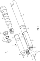
- the drug delivery device 10 as illustrated in Fig. 1 in an exploded view comprises a two-component housing having a proximal main housing section 14 and a distally located cartridge holder section 12.
- the cartridge holder section 12 is adapted to receive a cartridge 17, which is typically filled with a fluid medicinal product.
- the cartridge 17, in particular its sidewall 18, is of tubular shape and receives a moveable piston or bung 20 which seals the interior of the cartridge 17 in proximal direction.
- the cartridge 17 or the cartridge wall 18 comprises a stepped down neck portion or bottle neck portion, which is sealed by a septum 24.
- the septum 24 in turn is fixed to the cartridge wall 18 by means of a fixing sleeve 22, typically designed as an aluminium crimp.
- a needle assembly 26 having a cupped needle mount 30 can be screwed on a threaded stepped down portion 32 at the distal end of a cartridge holder section 12.
- the piercing element or injection needle 28 is permanently connected with the needle mount 30.
- the needle mount 30 at its inner sidewall comprises a thread 33 corresponding with the thread of a distal end section 32 of the cartridge holder 12.
- the needle 28 extends in distal as well as in a proximal direction. With a proximally located tipped end 29, the injection needle 28 may penetrate the septum 24 of the cartridge 17.
- the cartridge 17 itself is spring-biased and axially displaceably supported inside the cartridge holder section 12 as illustrated in Figures 14 and 16 .
- the distal end section of the cartridge holder section 12 comprises a proximally directed and inwardly extending shaft 40 that forms a slit-like circumferential receptacle 42 to receive the helical compression spring 31.
- the compression spring 31 abuts against the distal end face of the cartridge 17.
- the spring 31 abuts with the fixing sleeve 22 of the cartridge.
- the axially inwardly extending shaft 40 may additionally serve as a stopper to delimit a distally directed displacement of the cartridge 17.
- axial extension of the shaft 40 may specify the distal stop position of the cartridge 17 with respect to the housing component 12.
- the two housing components 12, 14 are adapted to be assembled in a nested or interleaved way.
- the cartridge holder section 12 comprises an annular rim 36, that abuts with a distal end face of the main housing component 14.
- the cartridge holder section 12 comprises numerous recesses 38 that are adapted to receive radially inwardly protruding catch elements 82 of the tubular shaped main housing section 14 as they are apparent from in Figure 4 . In this way, cartridge holder section 12 and main housing section 14 can be positively and releaseably engaged with respect to each other.
- the cartridge holder section 12 comprises an inspection window 34, which allows to visually control the filling level of the cartridge 17.
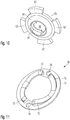
- the drug delivery device 10 further comprises a clutch assembly 50 having a first clutch element 52, a second clutch element 54 and an intermediary spring element 56.
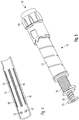
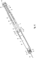
- the main housing section 14 is generally adapted to house the drive mechanism 16, which is separately illustrated in Figure 5 .
- the drive mechanism 16 comprises a piston rod 88 and a drive sleeve 90 threadedly engaged with the piston rod 88.
- the drive mechanism 16 comprises various clutch means, e.g. a clutch sleeve 98 arranged between an outer dose dial sleeve 92 and a drive sleeve 90.
- the drive mechanism 16 comprises a dose dial button 94 that allows to select and to set a predefined dose.
- the drive mechanism 16 illustrated in the present embodiment is almost identical to the drive mechanism of a pen-type injector as already known from WO 2004/078241 A1 .
- Bearing 86 and piston rod 88 are preferably positively locked, wherein the bearing 86 remains free to rotate with respect to the piston rod's 88 long axis. Said bearing 86 is further adapted to abut against a proximal end face of the cartridge's piston 20 and to transfer thrust to the piston 20 for expelling a pre-defined dose of the medicinal product from the cartridge 17.
- the piston rod 88 comprises a distal thread, which is engaged with the through openings 58, 60 of first and second clutch elements 52, 54. Even though not explicitly illustrated, the piston rod 88 further comprises a proximal thread engaged with a corresponding inner thread of the drive sleeve 90. Typically, proximal thread and distal thread of the piston rod 88 are oppositely handed and comprise different leads.
- the threaded engagement of the piston rod 88 and the drive sleeve 90 is of non-self-locking type. In this way, an axially directed displacement of the drive sleeve 90 leads to a respective rotation of the piston rod 88 and due to the threaded engagement of piston rod 88 and the clutch assembly 50 to a respective relative axial displacement of piston rod 88 and sidewall 18 of the cartridge 17, when the cartridge 17 is in its distal stop position.
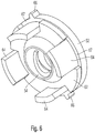
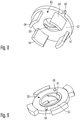
- the clutch assembly 50 comprises a first clutch element 52 and a second clutch element 54. Both clutch elements 52, 54 are of disk-like shape and comprise co-linearly arranged threaded through openings 58, 60, as indicated in Figures 7 and 10 .
- Through opening 58 of the first clutch element 52 comprises an inner thread 59
- through opening 60 of the second clutch element 54 comprises an inner thread 61.
- Both threads 59, 61 substantially comprise the same lead. Threads 59 and 61 further correspond to the outer thread of the piston rod 88.
- the first clutch element 52 comprises two diametrically arranged and radially extending protrusions 66 at its outer circumference. With these protrusions 66, the first clutch element 52 is secured against rotation inside the main housing section 14. At its inner sidewall, main housing section 14 comprises two oppositely arranged and axially extending grooves 84 adapted to receive the protrusions 66 of the first clutch element 52. In this way, the first clutch element 52 and the entire clutch assembly 50 become axially displaceable but rotatably locked with respect to the housing 14.
- the first clutch element 52 further comprises four regularly arranged strut sections 64 that extend in distal direction.
- Said strut sections 64 are integrally formed with the disk-shape section of the first clutch element 52 which comprises the threaded through opening 58.
- the strut sections 64 are of substantially quadratic or rectangular shape. They are further arranged near the outer circumference of the first clutch element 52.
- the strut sections 64 are shifted radially inwards, such that a socket 67 forms between the outer edge of the clutch element 52 and its strut sections 64, respectively.
- the strut sections 64 are arc-shaped according to the substantially circular circumference of the first clutch element 52.
- first and second clutch elements 52, 54 are displaceably arranged in axial direction. But first and second clutch elements 52, 54 are rotatably secured with respect to each other.
- the second clutch element 54 comprises four recesses 63 between the radially extending and wedge-shaped protrusions 62.
- these recesses 63 are adapted to receive the strut sections 64 of the first clutch element 52.
- first and second clutch elements 52, 54 a disk-shaped compression spring 56 is arranged.
- the compression spring 56 comprises an outer collar intersected by two oppositely arranged receptacles 70.
- the spring element 56 can be rotatably secured with the second clutch element 54, in particular, when the proximally extending pins 68 of the second clutch element 54 extend through the through openings 70 of the spring element 56.
- Radially inwardly, the spring element 56 comprises four spring arms 72 that extend in proximal direction and abut against an inner surface of the first clutch element 52. Per default and if no external forces are applied, the spring element 56 will keep first and second clutch elements 52, 54 in an axial distance 76 as illustrated in Figure 15 . Since both clutch elements 52, 54 are threadedly engaged with the piston rod 88, by way of separating first and second clutch elements 52, 54, the piston rod 88 can be rotatably secured and clamped with the clutch assembly 50.
- any distally applied thrust 96 acting on the dose button 100 leads to an axial and distally directed displacement of cartridge 17, clutch assembly 50 and drive mechanism 16 until the cartridge 18 and the clutch assembly 50 reach their respective proximal stop positions.
- proximal stop position of the cartridge 17 and proximal stop position of the clutch assembly 50 are correlated with respect to each other.
- the cartridge 17 is in its distal stop position when the cupped fixing sleeve 22 abuts with a proximal end face of the proximally inwardly directed shaft 40 of the cartridge holder section 12 of the housing.
- the clutch assembly 50 in particular its second clutch element 54 reaches its distal stop position, when the wedge-shaped and radially extending protrusion 62 of the second clutch element 54 props against the stop element 44, which, in the illustrated embodiment, coincides with the proximal end face of the cartridge holder section 12.
- the clutch assembly 50 In an initial configuration of the drug delivery device 10 as illustrated in Figure 14 , the clutch assembly 50 is in a locking configuration. First and second clutch elements 52, 54 are separated by a gap 76 under the effect of the intermediary spring 56. As can be further seen in Figure 15 , the clutch assembly 50 is in its proximal stop position and the first clutch element 52 buts against a radially inwardly extending stop 80, which, in the present embodiment is integrally formed with the main housing section 14.
- a predefined dose to be injected can be selected, e.g. by dialling of the dose dial button 54. Consequently, the drive mechanism is displaced in proximal direction as illustrated in Figure 16 .
- a fluid-transferring coupling of injection needle 28 and cartridge 17 is achieved and conducted during a subsequent dose dispensing procedure.
- a user may exert distally directed thrust 96 to the dose button 100 as indicated in Figure 17 .
- the entire arrangement of cartridge 17, clutch assembly 50 and drive mechanism 16 is displaced in distal direction, because the piston rod 88 is hindered to rotatably move.
- cartridge 17, clutch assembly 50 and drive mechanism 16 are subject to a distally directed displacement until the cartridge 17 and/or the clutch assembly 50 reach their distal stop position.
- the applied thrust 96 is almost exclusively transferred to the sidewall 18 of the cartridge 17 via the first clutch element 52 and by means of its axially extending strut sections 64.
- the piston rod 88 becomes free to rotate and hence to conduct a combined rotational and distally directed movement with respect to the sidewall or housing 18 of the cartridge 17.
- the piston 20 can be driven in distal direction by a pre-defined distance governed by the size of the previously set dose.
- the two-fold threaded engagement of the piston rod 88 with respect to the drive sleeve 90 as well as with respect to the rotatably locked clutch assembly 50 provides a beneficial reduction gear mechanism with its gear ratio being governed by the ratio of the different leads at opposite end sections of the piston rod 88.
- the present invention is exemplary illustrated with only one representative drive mechanism 16, the releasable coupling of piercing element 28 and cartridge 17 as well as the axial displacement of the drive mechanism 16 and the cartridge 17 is generally not limited to a single drive mechanism. It may be universally applied to a variety of drive mechanisms, wherein a piston rod 88 is generally subject to an axial and/or rotational movement during dose dispensing.
- distally applied thrust 96 is typically reduced.
- the spring element 31 tends to displace the entire assembly of cartridge 17, clutch assembly 50 and drive mechanism 16 to their respective proximal stop positions, thereby disconnecting cartridge 17 and injection needle 28.
- the spring element 56 of the clutch assembly 50 tends to axially separate first and second clutch elements 52, 54, such that the clutch 50 returns into its default interlocking configuration.
- droplet generation which might be due to elastic relaxation of septum 24 and/or piston 20, can be effectively minimized or even entirely eliminated.
Description
- The present invention relates to a drug delivery device such as a pen-type injector, to a cartridge to be removably arranged inside such drug delivery devices and to a corresponding drive mechanism, wherein a single or a number of pre-set doses of a medicinal product can be administered. In particular, the invention relates to such drug delivery devices being designed for self-administration of a medicinal product.
- Drug delivery devices allowing for multiple dosing of a required dosage of a liquid medicinal product, such as liquid drugs, and further providing administration of the liquid to a patient, are as such well-known in the art. Generally, such devices have substantially the same purpose as that of an ordinary syringe.
- Pen-type injectors of this kind have to meet a number of user specific requirements. For instance in case of those with diabetes, many users will be physically infirm and may also have impaired vision. Therefore, these devices need to be robust in construction, yet easy to use, both in terms of the manipulation of the parts and understanding by a user of its operation. Also, the dose setting must be easy and unambiguous and where the device is to be disposable rather than reusable, the device should be inexpensive to manufacture and easy to dispose. In order to meet these requirements, the number of parts and steps required to assemble the device and an overall number of material types the device is made from have to be kept to a minimum.
- The medicinal product to be dispensed by means of the drug delivery device is typically provided in a disposable or replaceable cartridge, such as a vial, ampoule or carpule comprising a slidably disposed piston to be operably engaged with a piston rod of a drive mechanism of the drug delivery device. By applying thrust to the cartridge's piston in distal direction, a predefined dose of the liquid drug can be dispensed and expelled from the cartridge.
- Cartridges as they are typically used with drug delivery devices, in particular with pen-type injectors are typically sealed by means of as septum. Such a septum is commonly designed as a rubber stopper providing an air-tight seal but being pierceable by piercing elements such as needles or cannulae.
- Typically, such drug delivery devices comprise a cartridge holder adapted to receive a cartridge which is hermetically sealed with such flexible and deformable septum. At its lower and distal end section, the cartridge holder can for instance be threadedly engaged with a needle mount. Said needle mount or needle holder typically comprises a correspondingly threaded cylindrical portion for releasably interconnecting needle holder and cartridge holder.
- During assembly of the needle holder the proximally located tipped end of the needle penetrates the septum of the cartridge. In this way, a fluid-transferring connection for the purpose of dose dispensing can be established.
- In particular, during dispensing of a dose of the medicinal fluid contained in the cartridge, a respective fluid pressure is built-up. During a dose dispensing procedure the piston is subject to an axial squeezing and/or the septum might become subject to an axial expansion. Due to their elastic properties, septum and/or piston may store elastic energy during dose dispensing. Right after completion of a dose dispensing procedure, the septum and/or the piston typically relax to their initial configuration, because the fluid pressure inside the cartridge drops. Since the piston is in an abutment position with a distally arranged bearing of a piston rod, relaxation of the piston inevitably leads to an expansion of the piston in distal direction. Similarly, the expanded section of the septum retracts into the cartridge.
- Both relaxing phenomena may in turn lead to a post-dispensing built-up of a non-negligible fluid pressure and, as a consequence, a certain amount of medicinal fluid may be supplementary expelled from the cartridge, which can be typically observed in the form of droplet formation at the distal tip of the needle, which remains in permanent fluid-transferring contact with the inner volume of the cartridge as long as the needle assembly remains connected with the cartridge holder.
- Additionally, such droplet formation may occur during assembly of the needle mount to the cartridge holder, especially, when the inside pressure of the cartridge is larger than ambient pressure. Since some dispensable medicinal products like Insulin or Erythropoietin (EPO) have to be stored refrigerated, a non-negligible pressure increase may for instance arise due to thermal expansion, e.g. if the cartridge or the drug delivery device is kept in a non-refrigerated environment at least for a while.
- Document
US 2006/0052747 A1 discloses a two-chamber pre-filed syringe including an outer cylinder and an inner cylinder assembly. When a plunger is gradually pressed toward a front-end side of the outer cylinder the inner cylinder assemblage moves toward the front-end side of the outer cylinder and the rear end of a projected portion for breaking a sealing member of a first gasket. - Document
US 2 842 126 A further discloses a syringe assembly having a barrel being sealed in distal direction by way of a rubber stopper. There, a distal cap acting as needle holder can be clipped onto a distal end section of the barrel. The cap and the barrel comprise mutually corresponding indentations in order to fix the cap to the barrel. - Document
US 2004/0111063 A1 discloses a pre-filled injection ampoule for administering a dose of fluid medication. There, a cartridge is fully depressed into a housing, wherein a sealing member is engaged by a detent formed at a forward position within the housing to retain the cartridge within the same. - Furthermore, document
US 3,401,693 A relates to a hypodermic syringe, wherein a needle hub is spring biased with respect to an annular flange of a distally located needle mount. There, once a needle cover has been removed, the spring is allowed to extent and to move the needle hub inwardly to penetrate the seal of a cartridge. - It is therefore an object of the present invention, to provide a drug delivery device which is less prone to droplet-generation, preferably both during needle assembly as well as after completion of a dose dispensing procedure. The invention further focuses on a reliable, cost-efficient mechanism for droplet prevention, which is easy to assemble and which can be universally applied to a variety of drive mechanisms for drug delivery devices.
- The present invention provides a drug delivery device for dispensing of a dose of a medicinal product. The drug delivery device comprises a housing, typically a two-component housing having a proximally located main housing section and a distally located cartridge holder section, wherein the main housing section is substantially adapted to receive a drive mechanism of the drug delivery device and wherein the cartridge holder section is adapted to hold and to receive a cartridge that contains the medicinal product to be dispensed by the drug delivery device, preferably by injection.
- The drive mechanism of the drug delivery device comprises an axially displaceable piston rod which operably engages and at least unidirectionally acts on a piston of a cartridge. The cartridge itself is preferably designed as disposable and replaceable article. Generally, the cartridge is not a constituent of the drug delivery device. Only in such embodiments, wherein the entire drug delivery device is constructed as a disposable device, the cartridge may be regarded as integral component of the drug delivery device.
- The cartridge is typically designed as vial, carpule or ampoule. It is filled or it is to be filled with a medicinal product to be dispensed a well-defined way, typically in multiple doses.
- The cartridge containing a liquid drug like Heparin or Insulin is hermetically sealed at its distal end face, typically by means of a flexible and deformable septum, which is penetrable by a piercing element, such as an injection needle or a cannula. The housing, in particular the distal end section of the cartridge holder section, is adapted to support a replaceable piercing element, which is to be coupled to the interior of the cartridge in a fluid transferring way at least for dose dispensing.
- The present invention is particularly characterized by means for reversibly displacing the cartridge in axial direction with respect to the housing. In particular, the cartridge is at least displaceable from a proximal stop position to a distal stop position. Transition of the cartridge from the proximal stop position to the distal stop position is typically characterized by a linear axial movement along the axis of symmetry of the housing, i.e, along the housing's long axis. In the present context, reversible displacement of the cartridge means, that the cartridge is intended to be displaced in axial direction back and forth between its proximal and distal stop position.
- In the proximal stop position, the cartridge is disconnected from the piercing element, preferably such that a fluid-transferring coupling of piercing element and inside volume of the cartridge is interrupted. However, in its distal stop position, the cartridge is connected to the piercing element in a fluid transferring way. At least when reaching its distal stop position, the distal end face of the cartridge, i.e. its septum, is penetrated and intersected by the piercing element.
- Axial displacement of the cartridge inside the housing is preferably activated and controlled by the drive mechanism. Drive mechanism and cartridge are therefore operably engaged. It is of particular benefit, when the cartridge is in its proximal stop position during assembly of the piercing element and the housing. In this way, the piercing element does not intersect or penetrate the cartridge's septum prior injection. Septum penetration preferably occurs at a later stage, preferably during a dose dispensing action, in which the cartridge and the drive mechanism in its entirety become subject to a distally directed axial displacement.
- Furthermore, the present invention also intends to provide a self-actuated disconnecting of piercing element and cartridge as soon as a dose dispensing procedure has terminated. Hence, the means for displacing the cartridge are adapted to displace the cartridge bi-directionally on demand. Since the cartridge can be disconnected from the piercing element after termination of a dose dispensing procedure, the phenomenon of post-dispensing droplet generation, which might be due to relaxation processes of elastic components of the cartridge can be effectively eliminated or at least remarkably reduced.
- The means for displacing the cartridge are adapted to reversibly displace the cartridge in the housing between the proximal and the distal stop position. Therefore, the cartridge is displaceably supported in the housing in axial direction in a bidirectional way, that allows for a selective connecting and disconnecting of cartridge and piercing element, respectively.
- Furthermore, the cartridge is spring-supported in distal direction against a distal end section of the housing. Here, a spring element, preferably a compression spring element, is disposed inside the cartridge holder in such a way, that the spring element is compressed and stores mechanical energy during a distally directed displacement of the cartridge. This compression spring element serves to provide a self-actuating disconnecting of cartridge and piercing element, in particular after completion of a dose dispensing procedure.
- In a preferred embodiment, the drive mechanism is adapted to selectively act on a proximal end section of the cartridge's sidewall and/or to act on a proximal end face of the piston. According to this embodiment, the drive mechanism provides multiple functions. By way of the drive mechanism, the cartridge itself can be displaced in distal direction with respect to the housing or the cartridge holder. Once the cartridge has reached its distal stop position, the drive mechanism is furthermore adapted to exert distally directed thrust to a proximal end face of the cartridge's piston in order to distally displace the piston for the purpose of expelling of a pre-defined amount of the liquid medicinal product.
- Preferably, a dose injection process splits in two subsequent steps. In a first step, the cartridge is displaced in distal direction until it rests in its distal stop position. In a subsequent second step, further distally directed thrust is selectively directed onto the cartridge's piston for conducting the dose dispensing. Here, the drive mechanism selectively provides distal displacement of the cartridge with respect to the housing as well as distal displacement of the cartridge's piston with respect to the sidewall of the cartridge. These different ways of relative displacement of cartridge and piston are preferably conducted sequentially but not combined. In this way, it can be ensured, that the piston starts to move with respect to the cartridge's sidewall when the cartridge itself is in its distal stop position, in which the cartridge is coupled to an injection needle or cannula in a fluid-transferring way.
- According to a further preferred embodiment, the piston rod is radially guided by a clutch assembly, which is adapted to transfer a distally directed thrust either to the cartridge's sidewall or to the piston of the cartridge. Depending on the respective configuration of the clutch, a distally directed motion of a piston rod is either transferred to a distally directed displacement of the cartridge as a whole or to a distally directed displacement of the cartridge's piston, wherein the cartridge itself is axially fixed or interlocked with respect to the housing of the drug delivery device.
- According to another preferred embodiment of the invention, the clutch assembly is axially displaceably guided in the housing. This way, cartridge, clutch assembly as well as drive mechanism may become subject to a combined distally or proximally directed displacement for connecting or disconnecting cartridge and piercing element. Preferably, also the clutch assembly is axially displaceable between a proximal and a distal stop position, that are correlated to respective distal and proximal stop positions of the cartridge.
- In a further preferred aspect, the clutch assembly is secured against rotation with respect to the housing. The housing, typically of cylindrical or tubular shape may comprise retention means at its inner surface of the sidewall, whereas the clutch means may comprise corresponding retention means at is outer circumference.
- In another embodiment, the clutch assembly is selectively convertible into a locking and a release configuration. In its locking configuration, the clutch assembly impedes a rotation of the piston rod with respect to the housing. Typically, the clutch assembly might be threadedly engaged or otherwise rotatably engaged with the clutch assembly. In its locking configuration, the clutch assembly substantially impedes a rotation of the piston rod relative to the clutch assembly. Therefore, a distally directed displacement of the piston rod directly transfers to the clutch assembly and to the sidewall of the cartridge.
- In its release configuration, the clutch assembly allows for an axial movement of the piston rod with respect to the cartridge's sidewall. Here, a distally directed displacement of the piston rod directly transfers to a respective displacement of the cartridge's piston.
- In embodiments, wherein the clutch assembly and the piston rod are threadedly engaged, the piston rod might be subject to a combined axial and rotational displacement with respect to the clutch assembly.
- Switching of the clutch assembly between a locking and a release configuration might be triggered by an axial compression of the clutch assembly itself. For instance, the clutch assembly may be in locking configuration per default setting and may enter into release configuration when reaching its distal stop position in the housing.
- According to a further preferred embodiment, the clutch assembly comprises a first and a second clutch element and an intermediary spring element, which is adapted to axially separate first and second clutch elements from each other. Consequently, the spring element sandwiched between first and second clutch elements serves to increase the axial expansion of the clutch assembly. First and second clutch elements are therefore axially biased by said spring element.
- In a further modification, the piston rod is threadedly engaged with both, the first and with the second clutch element. First and second clutch elements therefore comprise threaded through openings to receive the piston rod. Preferably, said through openings of first and second clutch elements comprise identical threads. Hence, the piston rod is retained and rotatably secured when first and second clutch elements are separated from each other under the effect of the intermediary spring element. The threaded engagement of the clutch elements and the piston rod is preferably of self-inhibiting type. It may even be of non-self-inhibiting type due to a clamping achieved by the spring-biased displacement of first and second clutch elements. This way, a rotational movement of the piston rod with respect to the clutch means or with respect to the housing can be effectively prevented.
- Since the clutch assembly itself is rotatably secured with respect to the housing, in its locked configuration, the clutch assembly allows for an axial displacement of the piston rod, typically combined by a respective and identical axial displacement of the clutch assembly.
- According to a further preferred embodiment, the first clutch element comprises at least one axially extending strut section, which at least partially and radially surrounds the second clutch element. Hence, first and second clutch elements are arranged in an at least partially interleaved manner. The at least one axially extending strut section of the first clutch element is also operably engaged with the sidewall of the cartridge. In typical embodiments, first and second clutch elements are arranged and configured in a nested way. Preferably, the first clutch element comprises at least two or even more strut sections being regularly arranged across the circumference of the first clutch element.
- Said axially and preferably distally directed strut sections form interstices at the circumference of the first clutch element, that are adapted to receive correspondingly shaped radial disk-like protrusions of the second clutch element.
- The spring element, which can be designed as spring washer, disk spring or as a disk-like washer comprising spring arms to be axially biased, is preferably at least rotatably locked with either the first and/or second clutch element.
- In another preferred embodiment of the invention, the second clutch element comprises at least one projection radially extending between adjacent strut sections of the first clutch element. During displacement of the cartridge to its distal stop position, said projection axially abuts against a stop element, typically, when said second clutch element reaches its distal stop position. The stop element, which can be designed as a component of the housing, impedes a further distally directed displacement of the second clutch element. In the course of a continuous distal displacement of the piston rod, the intermediary spring element then becomes subject to compression until the clutch assembly is transferred in its release configuration.
- In response to the clutch release, the piston rod is free to rotate, thereby becoming subject to an axial displacement with respect to the clutch assembly. Since the piston rod preferably remains in permanent contact to a proximal end face of the piston by means of a bearing, a distally directed and externally provided force acting on the drive mechanism splits into first and second distally directed thrust, that acts on the sidewall of the cartridge and on the piston, respectively.
- If at the end of a dose dispensing procedure, an externally applied force drops below a predefined threshold, the spring-biased cartridge will return to its proximal stop position. This movement may be accompanied by a respective mutual axial displacement of first and second clutch elements leading to a rotation-impeding locking of the clutch assembly.
- Hence, at the end of a distally directed displacement of the cartridge, the radially extending projections of the second clutch element abut against a stop element of the housing, such that first and second clutch elements are brought together against the action of the intermediary spring element. Consequently, the clutch assembly releases. In the opposite way, as soon as the thrust exerted on the drive mechanism drops below a predefined threshold, the spring element of the clutch as well as the spring element intermediary arranged between distal end sections of housing and cartridge serve to restore the device to its initial or default configuration.
- According to a further preferred embodiment, the stop element to be operably engaged with the second clutch element is designed as an integral component of either the main housing section or the cartridge holder section. In a preferred embodiment, the housing of the drug delivery device comprises two components, namely a main housing section and a cartridge holder section. Here, a proximal end section of the cartridge holder section is assembled in a distally located receptacle of the main housing section. Furthermore, a proximal end face of the cartridge holder section serves as an axial stop element. Hence, by assembling main housing section and cartridge holder section in a nested or interleaved manner, a circumferential stopper can be generated to be operably engaged with the clutch element.
- In a further aspect, the invention also provides a cartridge to interact with and to be inserted into a drug delivery device according to the present invention. The cartridge comprises a proximal end section sealed by an axially displaceable piston. Preferably, it is at least partially filled with the medicinal product to be dispensed. The cartridge further comprises a sealed distal end section, which preferably comprises a bottle-neck-like shape. The distal end section of the cartridge is sealed by a seal, such like a septum, being secured to the sidewall of the cartridge by means of e.g. a fixing sleeve. The fixing sleeve, which is preferably designed as a clamping or crimping element made of metal comprises a centric through opening, through which the piercing element is to be guided for piercing and penetrating the seal.
- The diameter or the surface of the fixing sleeve's through opening is smaller than 30 %, preferably smaller than 20 %, more preferably smaller 10 % and most preferably smaller than 5 % of the diameter or cross section of the fixing sleeve. In other words, the diameter or the surface of a pierceable section of the seal is particularly smaller than 30 %, 20 %, 10 % preferably smaller than 5 % of the diameter or cross section confined by the tubular section of the sidewall of the cartridge.
- Such small through openings of the fixing sleeve can in fact be realized because the piercing element is already in its final assembly position when the cartridge is subject to a distal displacement in the direction to its distal stop position. Due to the radial guiding of the cartridge inside the housing, a sufficiently precise piercing of the seal can be achieved.
- Therefore, the pierceable area of the cartridge's distal end section can be remarkably reduced compared to conventional liquid drug-containing cartridges. Since the effective surface of the septum is drastically reduced, the septum also becomes less prone to a distally directed protrusion during a dose dispensing procedure. Also by downsizing the piercable seal of the cartridge, post-dispending droplet generation can be counteracted.
- The term "medicament" or "medicinal product", as used herein, means a pharmaceutical formulation containing at least one pharmaceutically active compound,
wherein in one embodiment the pharmaceutically active compound has a molecular weight up to 1500 Da and/or is a peptide, a proteine, a polysaccharide, a vaccine, a DNA, a RNA, a antibody, an enzyme, an antibody, a hormone or an oligonucleotide, or a mixture of the above-mentioned pharmaceutically active compound,
wherein in a further embodiment the pharmaceutically active compound is useful for the treatment and/or prophylaxis of diabetes mellitus or complications associated with diabetes mellitus such as diabetic retinopathy, thromboembolism disorders such as deep vein or pulmonary thromboembolism, acute coronary syndrome (ACS), angina, myocardial infarction, cancer, macular degeneration, inflammation, hay fever, atherosclerosis and/or rheumatoid arthritis,
wherein in a further embodiment the pharmaceutically active compound comprises at least one peptide for the treatment and/or prophylaxis of diabetes mellitus or complications associated with diabetes mellitus such as diabetic retinopathy,
wherein in a further embodiment the pharmaceutically active compound comprises at least one human insulin or a human insulin analogue or derivative, glucagon-like peptide (GLP-1) or an analogue or derivative thereof, or exedin-3 or exedin-4 or an analogue or derivative of exedin-3 or exedin-4. - Insulin analogues are for example Gly(A21), Arg(B31), Arg(B32) human insulin; Lys(B3), Glu(B29) human insulin; Lys(B28), Pro(B29) human insulin; Asp(B28) human insulin; human insulin, wherein proline in position B28 is replaced by Asp, Lys, Leu, Val or Ala and wherein in position B29 Lys may be replaced by Pro; Ala(B26) human insulin; Des(B28-B30) human insulin; Des(B27) human insulin and Des(B30) human insulin. Insulin derivates are for example B29-N-myristoyl-des(B30) human insulin; B29-N-palmitoyl-des(B30) human insulin; B29-N-myristoyl human insulin; B29-N-palmitoyl human insulin; B28-N-myristoyl LysB28ProB29 human insulin; B28-N-palmitoyl-LysB28ProB29 human insulin; B30-N-myristoyl-ThrB29LysB30 human insulin; B30-N-palmitoyl- ThrB29LysB30 human insulin; B29-N-(N-palmitoyl-Y-glutamyl)-des(B30) human insulin; B29-N-(N-lithocholyl-Y-glutamyl)-des(B30) human insulin; B29-N-(ω-carboxyheptadecanoyl)-des(B30) human insulin and B29-N-(ω-carboxyheptadecanoyl) human insulin.
- Exendin-4 for example means Exendin-4(1-39), a peptide of the sequence H-His-Gly-Glu-Gly-Thr-Phe-Thr-Ser-Asp-Leu-Ser-Lys-Gln-Met-Glu-Glu-Glu-Ala-Val-Arg-Leu-Phe-Ile-Glu-Trp-Leu-Lys-Asn-Gly-Gly-Pro-Ser-Ser-Gly-Ala-Pro-Pro-Pro-Ser-NH2.
- Exendin-4 derivatives are for example selected from the following list of compounds:
- H-(Lys)4-des Pro36, des Pro37 Exendin-4(1-39)-NH2,
- H-(Lys)5-des Pro36, des Pro37 Exendin-4(1-39)-NH2,
- des Pro36 [Asp28] Exendin-4(1-39),
- des Pro36 [IsoAsp28] Exendin-4(1-39),
- des Pro36 [Met(0)14, Asp28] Exendin-4(1-39),
- des Pro36 [Met(0)14, IsoAsp28] Exendin-4(1-39),
- des Pro36 [Trp(02)25, Asp28] Exendin-4(1-39),
- des Pro36 [Trp(02)25, IsoAsp28] Exendin-4(1-39),
- des Pro36 [Met(0)14 Trp(02)25, Asp28] Exendin-4(1-39),
- des Pro36 [Met(0)14 Trp(02)25, IsoAsp28] Exendin-4(1-39); or
- des Pro36 [Asp28] Exendin-4(1-39),
- des Pro36 [IsoAsp28] Exendin-4(1-39),
- des Pro36 [Met(0)14, Asp28] Exendin-4(1-39),
- des Pro36 [Met(0)14, IsoAsp28] Exendin-4(1-39),
- des Pro36 [Trp(02)25, Asp28] Exendin-4(1-39),
- des Pro36 [Trp(02)25, IsoAsp28] Exendin-4(1-39),
- des Pro36 [Met(0)14 Trp(02)25, Asp28] Exendin-4(1-39),
- des Pro36 [Met(O)14 Trp(02)25, IsoAsp28] Exendin-4(1-39),
- wherein the group -Lys6-NH2 may be bound to the C-terminus of the Exendin-4 derivative;
- or an Exendin-4 derivative of the sequence
H-(Lys)6-des Pro36 [Asp28] Exendin-4(1-39)-Lys6-NH2,
des Asp28 Pro36, Pro37, Pro38Exendin-4(1-39)-NH2,
H-(Lys)6-des Pro36, Pro38 [Asp28] Exendin-4(1-39)-NH2,
H-Asn-(Glu)5des Pro36, Pro37, Pro38 [Asp28] Exendin-4(1-39)-NH2,
des Pro36, Pro37, Pro38 [Asp28] Exendin-4(1-39)-(Lys)6-NH2,
H-(Lys)6-des Pro36, Pro37, Pro38 [Asp28] Exendin-4(1-39)-(Lys)6-NH2,
H-Asn-(Glu)5-des Pro36, Pro37, Pro38 [Asp28] Exendin-4(1-39)-(Lys)6-NH2,
H-(Lys)6-des Pro36 [Trp(02)25, Asp28] Exendin-4(1-39)-Lys6-NH2,
H-des Asp28 Pro36, Pro37, Pro38 [Trp(02)25] Exendin-4(1-39)-NH2,
H-(Lys)6-des Pro36, Pro37, Pro38 [Trp(02)25, Asp28] Exendin-4(1-39)-NH2,
H-Asn-(Glu)5-des Pro36, Pro37, Pro38 [Trp(02)25, Asp28] Exendin-4(1-39)-NH2,
des Pro36, Pro37, Pro38 [Trp(02)25, Asp28] Exendin-4(1-39)-(Lys)6-NH2,
H-(Lys)6-des Pro36, Pro37, Pro38 [Trp(02)25, Asp28] Exendin-4(1-39)-(Lys)6-NH2,
H-Asn-(Glu)5-des Pro36, Pro37, Pro38 [Trp(02)25, Asp28] Exendin-4(1-39)-(Lys)6-NH2,
H-(Lys)6-des Pro36 [Met(0)14, Asp28] Exendin-4(1-39)-Lys6-NH2,
des Met(0)14 Asp28 Pro36, Pro37, Pro38 Exendin-4(1-39)-NH2,
H-(Lys)6-desPro36, Pro37, Pro38 [Met(0)14, Asp28] Exendin-4(1-39)-NH2,
H-Asn-(Glu)5-des Pro36, Pro37, Pro38 [Met(0)14, Asp28] Exendin-4(1-39)-NH2,
des Pro36, Pro37, Pro38 [Met(0)14, Asp28] Exendin-4(1-39)-(Lys)6-NH2,
H-(Lys)6-des Pro36, Pro37, Pro38 [Met(0)14, Asp28] Exendin-4(1-39)-(Lys)6-NH2,
H-Asn-(Glu)5 des Pro36, Pro37, Pro38 [Met(0)14, Asp28] Exendin-4(1-39)-(Lys)6-NH2,
H-Lys6-des Pro36 [Met(0)14, Trp(02)25, Asp28] Exendin-4(1-39)-Lys6-NH2,
H-des Asp28 Pro36, Pro37, Pro38 [Met(0)14, Trp(02)25] Exendin-4(1-39)-NH2,
H-(Lys)6-des Pro36, Pro37, Pro38 [Met(0)14, Asp28] Exendin-4(1-39)-NH2,
H-Asn-(Glu)5-des Pro36, Pro37, Pro38 [Met(0)14, Trp(02)25, Asp28] Exendin-4(1-39)-NH2,
des Pro36, Pro37, Pro38 [Met(0)14, Trp(02)25, Asp28] Exendin-4(1-39)-(Lys)6-NH2,
H-(Lys)6-des Pro36, Pro37, Pro38 [Met(O)14, Trp(02)25, Asp28] Exendin-4(S1-39)-(Lys)6-NH2,
H-Asn-(Glu)5-des Pro36, Pro37, Pro38 [Met(0)14, Trp(02)25, Asp28] Exendin-4(1-39)-(Lys)6-NH2;
or a pharmaceutically acceptable salt or solvate of any one of the afore-mentioned Exedin-4 derivative. - Hormones are for example hypophysis hormones or hypothalamus hormones or regulatory active peptides and their antagonists as listed in Rote Liste, ed. 2008,
Chapter 50, such as Gonadotropine (Follitropin, Lutropin, Choriongonadotropin, Menotropin), Somatropine (Somatropin), Desmopressin, Terlipressin, Gonadorelin, Triptorelin, Leuprorelin, Buserelin, Nafarelin, Goserelin. - A polysaccharide is for example a glucosaminoglycane, a hyaluronic acid, a heparin, a low molecular weight heparin or an ultra low molecular weight heparin or a derivative thereof, or a sulphated, e.g. a poly-sulphated form of the above-mentioned polysaccharides, and/or a pharmaceutically acceptable salt thereof. An example of a pharmaceutically acceptable salt of a poly-sulphated low molecular weight heparin is enoxaparin sodium.
- Pharmaceutically acceptable salts are for example acid addition salts and basic salts. Acid addition salts are e.g. HCI or HBr salts. Basic salts are e.g. salts having a cation selected from alkali or alkaline, e.g. Na+, or K+, or Ca2+, or an ammonium ion N+(R1)(R2)(R3)(R4), wherein R1 to R4 independently of each other mean: hydrogen, an optionally substituted C1-C6-alkyl group, an optionally substituted C2-C6-alkenyl group, an optionally substituted C6-C10-aryl group, or an optionally substituted C6-C10-heteroaryl group. Further examples of pharmaceutically acceptable salts are described in "Remington's Pharmaceutical Sciences" 17. ed. Alfonso R. Gennaro (Ed.), Mark Publishing Company, Easton, Pa., U.S.A., 1985 and in Encyclopedia of Pharmaceutical Technology.
- Pharmaceutically acceptable solvates are for example hydrates.
- Without limitation, the present invention will be explained in greater detail below in connection with preferred embodiments and with reference to the drawings in which:
-
Figure 1 illustrates the various components of the drug delivery device in a perspective exploded illustration, -
Figure 2 shows the cartridge holder section in a perspective view, -
Figure 3 shows the cartridge holder section in a partially cut view, -
Figure 4 illustrates the main housing section partially cut, -
Figure 5 illustrates the drive mechanism in a perspective view, -
Figure 6 is illustrative of the clutch assembly, -
Figure 7 shows the clutch assembly in an exploded view, -
Figure 8 shows the first clutch element in a perspective illustration, -
Figure 9 is illustrative of the second clutch element as seen from proximal direction and -
Figure 10 shows the second clutch element as seen from a distal point of view, -
Figure 11 perspectively illustrates the intermediary spring element, -
Figure 12 illustrates the distal end section of the cartridge in an enlarged perspective view, -
Figure 13 shows the needle mount partially cut, -
Figure 14 illustrates the entire drug delivery device in a cross-sectional view in a default configuration, -
Figure 15 illustrates an enlarged part of the configuration according toFigure 14 with the clutch assembly in locking configuration, -
Figure 16 is illustrative of the pen-type drug delivery device during or after setting of a dose, -
Figure 17 shows the drug delivery device according toFigure 16 but with cartridge and clutch assembly in their distal stop positions and -
Figure 18 shows an enlarged extract ofFigure 17 , wherein the released clutch assembly is in distal stop position. - The
drug delivery device 10 as illustrated inFig. 1 in an exploded view comprises a two-component housing having a proximalmain housing section 14 and a distally locatedcartridge holder section 12. Thecartridge holder section 12 is adapted to receive acartridge 17, which is typically filled with a fluid medicinal product. Thecartridge 17, in particular itssidewall 18, is of tubular shape and receives a moveable piston or bung 20 which seals the interior of thecartridge 17 in proximal direction. In distal direction, thecartridge 17 or thecartridge wall 18 comprises a stepped down neck portion or bottle neck portion, which is sealed by aseptum 24. - The
septum 24 in turn is fixed to thecartridge wall 18 by means of a fixingsleeve 22, typically designed as an aluminium crimp. Aneedle assembly 26 having acupped needle mount 30 can be screwed on a threaded stepped downportion 32 at the distal end of acartridge holder section 12. As illustrated inFigure 13 , the piercing element orinjection needle 28 is permanently connected with theneedle mount 30. Theneedle mount 30 at its inner sidewall comprises athread 33 corresponding with the thread of adistal end section 32 of thecartridge holder 12. - The
needle 28 extends in distal as well as in a proximal direction. With a proximally located tippedend 29, theinjection needle 28 may penetrate theseptum 24 of thecartridge 17. Thecartridge 17 itself is spring-biased and axially displaceably supported inside thecartridge holder section 12 as illustrated inFigures 14 and16 . For this purpose, the distal end section of thecartridge holder section 12 comprises a proximally directed and inwardly extendingshaft 40 that forms a slit-likecircumferential receptacle 42 to receive thehelical compression spring 31. - The
compression spring 31 abuts against the distal end face of thecartridge 17. In particular, thespring 31 abuts with the fixingsleeve 22 of the cartridge. The axially inwardly extendingshaft 40 may additionally serve as a stopper to delimit a distally directed displacement of thecartridge 17. Hence, axial extension of theshaft 40 may specify the distal stop position of thecartridge 17 with respect to thehousing component 12. - The two
housing components Figures 1 and14 for example, thecartridge holder section 12 comprises anannular rim 36, that abuts with a distal end face of themain housing component 14. Moreover, thecartridge holder section 12 comprisesnumerous recesses 38 that are adapted to receive radially inwardly protrudingcatch elements 82 of the tubular shapedmain housing section 14 as they are apparent from inFigure 4 . In this way,cartridge holder section 12 andmain housing section 14 can be positively and releaseably engaged with respect to each other. - As further illustrated in
Figures 1 and2 thecartridge holder section 12 comprises aninspection window 34, which allows to visually control the filling level of thecartridge 17. - The
drug delivery device 10 further comprises aclutch assembly 50 having a firstclutch element 52, a secondclutch element 54 and anintermediary spring element 56. Themain housing section 14 is generally adapted to house thedrive mechanism 16, which is separately illustrated inFigure 5 . Thedrive mechanism 16 comprises apiston rod 88 and adrive sleeve 90 threadedly engaged with thepiston rod 88. Furthermore, thedrive mechanism 16 comprises various clutch means, e.g. aclutch sleeve 98 arranged between an outerdose dial sleeve 92 and adrive sleeve 90. Furthermore, thedrive mechanism 16 comprises adose dial button 94 that allows to select and to set a predefined dose. - By way of the proximally located
dose button 100, distally directed thrust can be exerted to theentire drive mechanism 16. Thedrive mechanism 16 illustrated in the present embodiment is almost identical to the drive mechanism of a pen-type injector as already known fromWO 2004/078241 A1 . -
Bearing 86 andpiston rod 88 are preferably positively locked, wherein the bearing 86 remains free to rotate with respect to the piston rod's 88 long axis. Said bearing 86 is further adapted to abut against a proximal end face of the cartridge'spiston 20 and to transfer thrust to thepiston 20 for expelling a pre-defined dose of the medicinal product from thecartridge 17. - The
piston rod 88 comprises a distal thread, which is engaged with the throughopenings clutch elements piston rod 88 further comprises a proximal thread engaged with a corresponding inner thread of thedrive sleeve 90. Typically, proximal thread and distal thread of thepiston rod 88 are oppositely handed and comprise different leads. - In preferred embodiments, the threaded engagement of the
piston rod 88 and thedrive sleeve 90 is of non-self-locking type. In this way, an axially directed displacement of thedrive sleeve 90 leads to a respective rotation of thepiston rod 88 and due to the threaded engagement ofpiston rod 88 and theclutch assembly 50 to a respective relative axial displacement ofpiston rod 88 andsidewall 18 of thecartridge 17, when thecartridge 17 is in its distal stop position. - In
Figures 6 through 10 , theclutch assembly 50 is illustrated in detail. Theclutch assembly 50 comprises a firstclutch element 52 and a secondclutch element 54. Bothclutch elements openings Figures 7 and10 . Through opening 58 of the firstclutch element 52 comprises aninner thread 59 and through opening 60 of the secondclutch element 54 comprises aninner thread 61. Boththreads Threads piston rod 88. - The first
clutch element 52 comprises two diametrically arranged and radially extendingprotrusions 66 at its outer circumference. With theseprotrusions 66, the firstclutch element 52 is secured against rotation inside themain housing section 14. At its inner sidewall,main housing section 14 comprises two oppositely arranged and axially extendinggrooves 84 adapted to receive theprotrusions 66 of the firstclutch element 52. In this way, the firstclutch element 52 and the entireclutch assembly 50 become axially displaceable but rotatably locked with respect to thehousing 14. - The first
clutch element 52 further comprises four regularly arrangedstrut sections 64 that extend in distal direction. Saidstrut sections 64 are integrally formed with the disk-shape section of the firstclutch element 52 which comprises the threaded throughopening 58. Thestrut sections 64 are of substantially quadratic or rectangular shape. They are further arranged near the outer circumference of the firstclutch element 52. Thestrut sections 64 are shifted radially inwards, such that asocket 67 forms between the outer edge of theclutch element 52 and itsstrut sections 64, respectively. Moreover, thestrut sections 64 are arc-shaped according to the substantially circular circumference of the firstclutch element 52. - As can be further seen from
Figures 15 and18 , thestrut sections 64 in distal direction abut against a proximal end face of the cylindrical sidewall of the cartridge. Hence, by way of thestrut sections 64, externally applied thrust can be transferred exclusively to thesidewall 18 of thecartridge 17 for the purpose of displacing thecartridge 17 in its distal stop position, which is illustrated inFigure 17 . - As further illustrated in
Figures 6 through 10 , thestrut sections 64 of the firstclutch element 52 are spaced apart from each other and formclearances 65 that are adapted to receive radially extending wedge-shapedprotrusion 62 of the disk-shaped secondclutch element 54. In this way, first and secondclutch elements clutch elements - Correspondingly, also the second
clutch element 54 comprises fourrecesses 63 between the radially extending and wedge-shapedprotrusions 62. In an assembly configuration, as illustrated inFigure 6 , theserecesses 63 are adapted to receive thestrut sections 64 of the firstclutch element 52. - Between first and second
clutch elements 52, 54 a disk-shapedcompression spring 56 is arranged. Thecompression spring 56 comprises an outer collar intersected by two oppositely arrangedreceptacles 70. By way of the tworeceptacles 70, thespring element 56 can be rotatably secured with the secondclutch element 54, in particular, when theproximally extending pins 68 of the secondclutch element 54 extend through the throughopenings 70 of thespring element 56. Radially inwardly, thespring element 56 comprises fourspring arms 72 that extend in proximal direction and abut against an inner surface of the firstclutch element 52. Per default and if no external forces are applied, thespring element 56 will keep first and secondclutch elements axial distance 76 as illustrated inFigure 15 . Since bothclutch elements piston rod 88, by way of separating first and secondclutch elements piston rod 88 can be rotatably secured and clamped with theclutch assembly 50. - Since the first
clutch element 52 is in turn rotatably secured with respect to themain housing section 14, consequently in said locking configuration, a rotational movement of thepiston rod 88 with respect to thehousing 14 is inhibited. Therefore, if theclutch assembly 50 is in its locking configuration, any distally applied thrust 96 acting on thedose button 100 leads to an axial and distally directed displacement ofcartridge 17,clutch assembly 50 anddrive mechanism 16 until thecartridge 18 and theclutch assembly 50 reach their respective proximal stop positions. - Preferably, proximal stop position of the
cartridge 17 and proximal stop position of theclutch assembly 50 are correlated with respect to each other. Thecartridge 17 is in its distal stop position when the cupped fixingsleeve 22 abuts with a proximal end face of the proximally inwardly directedshaft 40 of thecartridge holder section 12 of the housing. Theclutch assembly 50, in particular its secondclutch element 54 reaches its distal stop position, when the wedge-shaped and radially extendingprotrusion 62 of the secondclutch element 54 props against thestop element 44, which, in the illustrated embodiment, coincides with the proximal end face of thecartridge holder section 12. - In an initial configuration of the
drug delivery device 10 as illustrated inFigure 14 , theclutch assembly 50 is in a locking configuration. First and secondclutch elements gap 76 under the effect of theintermediary spring 56. As can be further seen inFigure 15 , theclutch assembly 50 is in its proximal stop position and the firstclutch element 52 buts against a radially inwardly extendingstop 80, which, in the present embodiment is integrally formed with themain housing section 14. - Starting from this initial configuration, a predefined dose to be injected can be selected, e.g. by dialling of the
dose dial button 54. Consequently, the drive mechanism is displaced in proximal direction as illustrated inFigure 16 . - It is further to be pointed out, that in the initial configuration of
Figure 14 as well as after setting of a dose as illustrated inFigure 16 , the inner volume of thecartridge 17 is not yet in fluid transferring contact with the proximally inwardly pointing tippedend 29 of theinjection needle 28. - A fluid-transferring coupling of
injection needle 28 andcartridge 17 is achieved and conducted during a subsequent dose dispensing procedure. For this purpose, a user may exert distally directed thrust 96 to thedose button 100 as indicated inFigure 17 . Under the effect of the applied thrust 96, and due to the interlocking provided by theclutch assembly 50, the entire arrangement ofcartridge 17,clutch assembly 50 anddrive mechanism 16 is displaced in distal direction, because thepiston rod 88 is hindered to rotatably move. - Consequently,
cartridge 17,clutch assembly 50 anddrive mechanism 16 are subject to a distally directed displacement until thecartridge 17 and/or theclutch assembly 50 reach their distal stop position. During this distally directed movement, the applied thrust 96 is almost exclusively transferred to thesidewall 18 of thecartridge 17 via the firstclutch element 52 and by means of its axially extendingstrut sections 64. - As soon as the second
clutch element 54 abuts against theproximal end face 44 of thecartridge holder section 12, as illustrated inFigure 18 , a further distally directed displacement of thepiston rod 88 leads to a compression of thespring element 56. The twoclutch elements piston rod 88 and the twoinner threads clutch assembly 50 is switched into its release configuration. - Consequently, the
piston rod 88 becomes free to rotate and hence to conduct a combined rotational and distally directed movement with respect to the sidewall orhousing 18 of thecartridge 17. This way, thepiston 20 can be driven in distal direction by a pre-defined distance governed by the size of the previously set dose. - In the illustrated embodiment, the two-fold threaded engagement of the
piston rod 88 with respect to thedrive sleeve 90 as well as with respect to the rotatably lockedclutch assembly 50 provides a beneficial reduction gear mechanism with its gear ratio being governed by the ratio of the different leads at opposite end sections of thepiston rod 88. - Even though the present invention is exemplary illustrated with only one
representative drive mechanism 16, the releasable coupling of piercingelement 28 andcartridge 17 as well as the axial displacement of thedrive mechanism 16 and thecartridge 17 is generally not limited to a single drive mechanism. It may be universally applied to a variety of drive mechanisms, wherein apiston rod 88 is generally subject to an axial and/or rotational movement during dose dispensing. - After completion of dose injection, distally applied thrust 96 is typically reduced. As soon as the
thrust 96 drops below a predefined threshold, thespring element 31 tends to displace the entire assembly ofcartridge 17,clutch assembly 50 anddrive mechanism 16 to their respective proximal stop positions, thereby disconnectingcartridge 17 andinjection needle 28. At the same time, thespring element 56 of theclutch assembly 50 tends to axially separate first and secondclutch elements - In such disconnected configuration droplet generation, which might be due to elastic relaxation of
septum 24 and/orpiston 20, can be effectively minimized or even entirely eliminated. -
- 10
- drug delivery device
- 12
- cartridge holder section
- 14
- main housing section
- 16
- drive mechanism
- 17
- cartridge
- 18
- sidewall
- 20
- piston
- 22
- fixing sleeve
- 24
- septum
- 26
- needle assembly
- 28
- injection needle
- 29
- tipped end
- 30
- needle mount
- 31
- compression spring
- 32
- threaded socket
- 33
- inner thread
- 34
- inspection window
- 36
- rim
- 38
- recess
- 40
- shaft
- 42
- receptacle
- 44
- stop element
- 50
- clutch assembly
- 52
- clutch element
- 54
- clutch element
- 56
- compression spring
- 58
- through opening
- 59
- inner thread
- 60
- through opening
- 61
- inner thread
- 62
- protrusion
- 63
- recess
- 64
- strut section
- 65
- clearance
- 66
- protrusion
- 67
- socket
- 68
- prong
- 70
- receptacle
- 72
- spring arm
- 74
- collar
- 76
- gap
- 80
- stop
- 82
- catch element
- 84
- groove
- 86
- bearing
- 88
- piston rod
- 90
- drive sleeve
- 92
- dose dial sleeve
- 94
- dose dial button
- 96
- thrust
- 98
- clutch sleeve
- 100
- dose button
Claims (13)
- Drug delivery device for dispensing of a dose of a medicinal product, comprising:- a housing having a proximal main housing section (14) and a distally located cartridge holder section (12);- a drive mechanism (16) comprising an axially displaceable piston rod (88) to act on a piston (20) of a cartridge (17) containing the medicinal product to be dispensed, wherein the cartridge holder section (12) is adapted to support a piercing element (29) which is adapted to penetrate a distal end face (24) of the cartridge (17), characterized by- means for reversibly displacing the cartridge (17) from a proximal stop position to a distal stop position in an axial direction and with respect to the housing, wherein the cartridge (17) is spring-supported in distal direction against a distal end section (32) of the cartridge holder section (12) by a compression spring (31) disposed inside the cartridge holder section (12), wherein the compression spring (31) abuts against a distal end face of the cartridge (17) and wherein in the distal stop position, the cartridge (17) is connected to the piercing element (29) and wherein in the proximal stop position, the cartridge (17) is disconnected from the piercing element (29) such that a fluid transfer between inside volume of the cartridge (17) and the piercing element (29) is interrupted.
- The drug delivery device according to claim 1, wherein the cartridge (17) is reversibly displaceably supported in the housing (12) between the proximal and distal stop position.
- The drug delivery device according to any one of the preceding claims, wherein the drive mechanism (16) is adapted to selectively act on a proximal end section of the cartridge's sidewall (18) and/or on a proximal end face of the piston (20).
- The drug delivery device according to any one of the preceding claims, wherein the piston rod (88) is radially guided by a clutch assembly (50) which is adapted to transfer a distally directed thrust (96) either to the sidewall (18) of the cartridge (17) or to the piston (20).
- The drug delivery device according to claim 4, wherein the clutch assembly (50) is axially displaceably guided in the housing (14).
- The drug delivery device according to any one of the preceding claims 4 or 5, wherein the clutch assembly (50) is secured against rotation with respect to the housing (14).
- The drug delivery device according to any one of the preceding claims 4 to 6, wherein in a locking configuration the clutch assembly (50) substantially impedes a rotation of the piston rod (88).
- The drug delivery device according to any one of the preceding claims 4 to 7, wherein the clutch assembly (50) in its release configuration allows for an axial movement of the piston rod (88) with respect to the sidewall (18) of the cartridge (17).
- The drug delivery device according to any one of the preceding claims 4 to 8, wherein the clutch assembly (50) comprises a first and a second clutch element (52, 54) and an intermediary spring element (56) adapted to axially separate first and second clutch elements (52, 54).
- The drug delivery device according to claim 9, wherein the piston rod (88) is threadedly engaged with the first (52) and with the second clutch element (54).
- The drug delivery device according to any one of the preceding claims 9 or 10, wherein the first clutch element (52) comprises at least one axially extending strut section (64) at least partially radially surrounding the second clutch element (54) and being further adapted to be operably engaged with the sidewall (18) of the cartridge (17).
- The drug delivery device according to any one of the preceding claims 9 to 11, wherein the second clutch element (54) comprises at least one projection (62) radially extending between adjacent strut sections (64) of the first clutch element (52), wherein during displacement of the cartridge (17) to its distal stop position, said projection (62) axially abuts against a stop element (44) of the housing (12, 14) such that first and second clutch elements (52, 54) are brought together against the action of the spring element (56) for releasing of the clutch assembly (50).
- The drug delivery device according to any one of the preceding claims, wherein the main housing section (14) is adapted to receive the drive mechanism (16) and wherein the cartridge holder section (12) is adapted to slidably receive the cartridge (17), wherein a proximal end section of the cartridge holder section (12) is arranged in a distally located receptacle of the main housing section (14), such that a proximal end face (44) of the cartridge holder section (12) serves as an axial stop element (44).
Priority Applications (3)
| Application Number | Priority Date | Filing Date | Title |
|---|---|---|---|
| DK16200302.4T DK3170526T3 (en) | 2009-10-30 | 2010-10-28 | CARTRIDGE FOR DRUG ADMINISTRATIVE DEVICE |
| EP16200302.4A EP3170526B1 (en) | 2009-10-30 | 2010-10-28 | Cartridge for a drug delivery device |
| EP10773053.3A EP2493532B1 (en) | 2009-10-30 | 2010-10-28 | Drug delivery device |
Applications Claiming Priority (3)
| Application Number | Priority Date | Filing Date | Title |
|---|---|---|---|
| EP09174670 | 2009-10-30 | ||
| EP10773053.3A EP2493532B1 (en) | 2009-10-30 | 2010-10-28 | Drug delivery device |
| PCT/EP2010/066313 WO2011051366A2 (en) | 2009-10-30 | 2010-10-28 | Drug delivery device |
Related Child Applications (2)
| Application Number | Title | Priority Date | Filing Date |
|---|---|---|---|
| EP16200302.4A Division-Into EP3170526B1 (en) | 2009-10-30 | 2010-10-28 | Cartridge for a drug delivery device |
| EP16200302.4A Division EP3170526B1 (en) | 2009-10-30 | 2010-10-28 | Cartridge for a drug delivery device |
Publications (2)
| Publication Number | Publication Date |
|---|---|
| EP2493532A2 EP2493532A2 (en) | 2012-09-05 |
| EP2493532B1 true EP2493532B1 (en) | 2019-07-10 |
Family
ID=42077342
Family Applications (2)
| Application Number | Title | Priority Date | Filing Date |
|---|---|---|---|
| EP16200302.4A Active EP3170526B1 (en) | 2009-10-30 | 2010-10-28 | Cartridge for a drug delivery device |
| EP10773053.3A Active EP2493532B1 (en) | 2009-10-30 | 2010-10-28 | Drug delivery device |
Family Applications Before (1)
| Application Number | Title | Priority Date | Filing Date |
|---|---|---|---|
| EP16200302.4A Active EP3170526B1 (en) | 2009-10-30 | 2010-10-28 | Cartridge for a drug delivery device |
Country Status (6)
| Country | Link |
|---|---|
| US (1) | US9180250B2 (en) |
| EP (2) | EP3170526B1 (en) |
| JP (1) | JP5856966B2 (en) |
| CA (1) | CA2778859A1 (en) |
| DK (2) | DK3170526T3 (en) |
| WO (1) | WO2011051366A2 (en) |
Families Citing this family (55)
| Publication number | Priority date | Publication date | Assignee | Title |
|---|---|---|---|---|
| ES2314182T3 (en) | 2002-02-11 | 2009-03-16 | Antares Pharma, Inc. | INTRADERMIC INJECTOR. |
| GB0304822D0 (en) | 2003-03-03 | 2003-04-09 | Dca Internat Ltd | Improvements in and relating to a pen-type injector |
| EP1850892B2 (en) | 2005-01-24 | 2023-04-19 | Antares Pharma, Inc. | Prefilled needle assisted syringe jet injector |
| WO2007131013A1 (en) | 2006-05-03 | 2007-11-15 | Antares Pharma, Inc. | Two-stage reconstituting injector |
| US9144648B2 (en) | 2006-05-03 | 2015-09-29 | Antares Pharma, Inc. | Injector with adjustable dosing |
| US8579866B2 (en) | 2008-01-11 | 2013-11-12 | Ucb Pharma, S.A. | Systems and methods for administering medication |
| WO2009114542A1 (en) | 2008-03-10 | 2009-09-17 | Antares Pharma, Inc. | Injector safety device |
| EP2318075B1 (en) | 2008-08-05 | 2019-05-22 | Antares Pharma, Inc. | Multiple dosage injector |
| DK2468344T3 (en) * | 2008-10-13 | 2013-12-09 | Sanofi Aventis Deutschland | Drug delivery device and method for manufacturing drug delivery device |
| EP2408493A1 (en) | 2009-03-20 | 2012-01-25 | Antares Pharma, Inc. | Hazardous agent injection system |
| CA2800562A1 (en) * | 2010-04-23 | 2011-10-27 | Sanofi-Aventis Deutschland Gmbh | Coded cartridge holder system for a fluid delivery device |
| DE202011110811U1 (en) * | 2010-08-06 | 2016-07-15 | Sanofi-Aventis Deutschland Gmbh | Cartridge holder for assembling a cartridge unit for a drug delivery device |
| EP2714144B1 (en) | 2011-06-02 | 2016-08-10 | UCB Biopharma SPRL | Auto-injector |
| US8496619B2 (en) | 2011-07-15 | 2013-07-30 | Antares Pharma, Inc. | Injection device with cammed ram assembly |
| US9220660B2 (en) | 2011-07-15 | 2015-12-29 | Antares Pharma, Inc. | Liquid-transfer adapter beveled spike |
| US9180446B2 (en) * | 2011-10-04 | 2015-11-10 | Eppendorf Ag | Manual dosing device |
| CN104582760A (en) | 2012-01-25 | 2015-04-29 | 诺沃—诺迪斯克有限公司 | Drug delivery device with cartridge fixation feature |
| JP6336401B2 (en) * | 2012-02-21 | 2018-06-06 | ノボ・ノルデイスク・エー/エス | Dose end indicator |
| AU2013224349A1 (en) | 2012-02-24 | 2014-08-21 | Novo Nordisk A/S | Drug delivery device with front loading feature |
| PT2822618T (en) | 2012-03-06 | 2024-03-04 | Antares Pharma Inc | Prefilled syringe with breakaway force feature |
| JP6457383B2 (en) | 2012-04-06 | 2019-01-23 | アンタレス・ファーマ・インコーポレーテッド | Needle-assisted jet injection of testosterone composition |
| DK2836259T3 (en) * | 2012-04-11 | 2016-09-12 | Sanofi Aventis Deutschland | CARTRIDGE HOLDER AND pen-like INJECTOR |
| WO2013169804A1 (en) | 2012-05-07 | 2013-11-14 | Antares Pharma, Inc. | Needle assisted jet injection device having reduced trigger force |
| CN104428020B (en) | 2012-06-29 | 2018-07-06 | 诺和诺德股份有限公司 | Spring driven injection device |
| US9757513B2 (en) | 2012-07-30 | 2017-09-12 | Ucb Biopharma Sprl | Auto-injector |
| WO2014019997A1 (en) | 2012-07-30 | 2014-02-06 | Ucb Pharma S.A. | Auto-injector |
| WO2014019999A1 (en) * | 2012-07-30 | 2014-02-06 | Ucb Pharma S.A. | Auto-injector |
| USD726901S1 (en) | 2012-07-30 | 2015-04-14 | Ucb Pharma S.A. | Drive device for administering medication |
| EP2879736B1 (en) | 2012-07-30 | 2018-11-14 | UCB Biopharma SPRL | Auto-injector |
| EP2928526B1 (en) * | 2012-12-10 | 2023-10-25 | Merck Sharp & Dohme LLC | Medication injector with near-empty alert |
| ES2763633T3 (en) | 2013-02-11 | 2020-05-29 | Antares Pharma Inc | Needle assisted jet injection device having reduced firing force |
| ES2742046T3 (en) | 2013-03-11 | 2020-02-12 | Antares Pharma Inc | Dose injector with pinion system |
| WO2014165136A1 (en) | 2013-03-12 | 2014-10-09 | Antares Pharma, Inc. | Constant volume prefilled syringes and kits thereof |
| DE102013007389A1 (en) * | 2013-04-30 | 2014-10-30 | Britannia Pharmaceuticals Ltd. | Drug delivery device |
| US9956349B2 (en) | 2013-05-21 | 2018-05-01 | Novo Nordisk A/S | Frontloaded drug delivery device with dynamic axial stop feature |
| WO2014187814A1 (en) | 2013-05-21 | 2014-11-27 | Novo Nordisk A/S | Frontloaded drug delivery device with actuated cartridge holder and piston rod coupling |
| EP2999504A1 (en) | 2013-05-21 | 2016-03-30 | Novo Nordisk A/S | Drug delivery device with piston rod coupling |
| GB201313888D0 (en) * | 2013-08-02 | 2013-09-18 | Consort Medical Plc | Assembly for an autoinjector device |
| WO2015071289A1 (en) | 2013-11-12 | 2015-05-21 | Novo Nordisk A/S | Drug delivery device with movable needle mount |
| CN105764552B (en) * | 2013-11-15 | 2019-11-29 | 赛诺菲-安万特德国有限公司 | Component and medicine delivery device for medicine delivery device |
| WO2015110533A2 (en) | 2014-01-27 | 2015-07-30 | Ucb Biopharma Sprl | Auto-injector |
| EP3099350B1 (en) | 2014-01-27 | 2019-06-12 | UCB Biopharma SPRL | Auto-injector |
| WO2015110532A1 (en) | 2014-01-27 | 2015-07-30 | Ucb Biopharma Sprl | Auto-injector |
| WO2015140262A1 (en) * | 2014-03-21 | 2015-09-24 | Novo Nordisk A/S | Drug delivery device with cap induced needle movement |
| GB201416985D0 (en) | 2014-09-26 | 2014-11-12 | Ucb Biopharma Sprl And Bespak Europ Ltd | Housing part for an auto-injector |
| TW201703802A (en) * | 2015-06-03 | 2017-02-01 | 賽諾菲阿凡提斯德意志有限公司 | Syringe support and autoinjector |
| WO2017174433A1 (en) | 2016-04-05 | 2017-10-12 | Novo Nordisk A/S | A torsion spring driven injection device |
| TWI637762B (en) | 2016-06-23 | 2018-10-11 | 卡貝歐洲有限公司 | Medicament delivery device |
| KR101911319B1 (en) * | 2017-01-06 | 2018-10-24 | 김성욱 | Medicine injection device |
| EP3621677B1 (en) * | 2017-05-09 | 2023-05-31 | SHL Medical AG | Transport lock assembly, and medicament delivery device comprising the transport lock assembly |
| CA2971263A1 (en) * | 2017-06-19 | 2018-12-19 | Duoject Medical Systems Inc. | Injector for drugs |
| US20190151551A1 (en) * | 2017-11-10 | 2019-05-23 | Abbvie Inc. | Delivery device with a connector having displaceable portions |
| EP3517153A1 (en) * | 2018-01-24 | 2019-07-31 | Insulcloud, S.L. | Monitoring device with universal adapter to drug injection pens |
| EP3758776A1 (en) * | 2018-03-01 | 2021-01-06 | Sanofi | Injection device with dose size adjuster |
| EP4164711A2 (en) * | 2020-06-12 | 2023-04-19 | Bexson Biomedical, Inc. | Systems and devices for controlled drug delivery |
Family Cites Families (19)
| Publication number | Priority date | Publication date | Assignee | Title |
|---|---|---|---|---|
| US2842126A (en) | 1954-03-16 | 1958-07-08 | Frederick M Turnbull | Syringe assembly |
| US2828742A (en) * | 1957-05-02 | 1958-04-01 | American Home Prod | Cartridge-needle unit |
| US3150661A (en) * | 1962-09-19 | 1964-09-29 | Cook Waite Lab Inc | Disposable cartridge and needle unit |
| US3401693A (en) * | 1965-10-19 | 1968-09-17 | Milton J. Cohen | Needle-hub assembly for hypodermic syringe |
| US4767413A (en) | 1987-04-20 | 1988-08-30 | Habley Medical Technology Corporation | Dental syringe having an automatically retractable needle |
| WO1996026751A1 (en) * | 1995-03-02 | 1996-09-06 | Sanofi Winthrop, Inc. | Low friction coating for cartridge seal cap |
| US7300416B2 (en) * | 1995-08-22 | 2007-11-27 | Specialized Health Products International | Pre-filled retractable needle injection ampoules |
| DK0902694T3 (en) * | 1995-08-22 | 2003-07-28 | Mdc Invest Holdings Inc | Pre-filled injection cartridge with retractable needle |
| WO1999016485A1 (en) * | 1997-09-29 | 1999-04-08 | Becton Dickinson And Company | Injection device and drug cartridge for preventing cross-use of the device and drug cartridge |
| JP3999489B2 (en) * | 2001-10-19 | 2007-10-31 | 住友ゴム工業株式会社 | Syringe |
| JP4112851B2 (en) * | 2001-11-27 | 2008-07-02 | テルモ株式会社 | Two-chamber prefilled syringe |
| GB0304822D0 (en) | 2003-03-03 | 2003-04-09 | Dca Internat Ltd | Improvements in and relating to a pen-type injector |
| EP1786478B1 (en) * | 2004-08-30 | 2012-12-05 | Bracco Diagnostic Inc. | Improved containers for pharmaceuticals, particularly for use in radioisotope generators |
| KR100624482B1 (en) | 2004-11-23 | 2006-09-18 | 삼성전자주식회사 | Tuning method and apparatus for decreasing interference between adjacent channels |
| US7645264B2 (en) * | 2005-04-11 | 2010-01-12 | Becton, Dickinson And Company | Injection device with secondary reservoir |
| EP2076302A1 (en) | 2006-09-15 | 2009-07-08 | TecPharma Licensing AG | Injection device with an automatically resettable dose limitation unit |
| WO2009127077A1 (en) * | 2008-04-14 | 2009-10-22 | 明辰股份有限公司 | Pre-filled automatically retractable safe injector |
| PL2451508T3 (en) * | 2009-07-08 | 2014-04-30 | Novo Nordisk As | Frost protected injection device |
| EP2311513A1 (en) * | 2009-10-16 | 2011-04-20 | Sanofi-Aventis Deutschland GmbH | Cartridge holder assembly for a drug delivery device |
-
2010
- 2010-10-28 CA CA2778859A patent/CA2778859A1/en not_active Abandoned
- 2010-10-28 EP EP16200302.4A patent/EP3170526B1/en active Active
- 2010-10-28 JP JP2012535819A patent/JP5856966B2/en active Active
- 2010-10-28 EP EP10773053.3A patent/EP2493532B1/en active Active
- 2010-10-28 WO PCT/EP2010/066313 patent/WO2011051366A2/en active Application Filing
- 2010-10-28 DK DK16200302.4T patent/DK3170526T3/en active
- 2010-10-28 DK DK10773053.3T patent/DK2493532T3/en active
- 2010-10-28 US US13/503,293 patent/US9180250B2/en active Active
Non-Patent Citations (1)
| Title |
|---|
| None * |
Also Published As
| Publication number | Publication date |
|---|---|
| JP5856966B2 (en) | 2016-02-10 |
| DK3170526T3 (en) | 2021-10-11 |
| US20130006192A1 (en) | 2013-01-03 |
| EP3170526B1 (en) | 2021-07-14 |
| WO2011051366A3 (en) | 2011-06-30 |
| EP3170526A1 (en) | 2017-05-24 |
| WO2011051366A2 (en) | 2011-05-05 |
| US9180250B2 (en) | 2015-11-10 |
| CA2778859A1 (en) | 2011-05-05 |
| DK2493532T3 (en) | 2019-10-07 |
| JP2013509215A (en) | 2013-03-14 |
| EP2493532A2 (en) | 2012-09-05 |
Similar Documents
| Publication | Publication Date | Title |
|---|---|---|
| EP2493532B1 (en) | Drug delivery device | |
| EP2437825B1 (en) | Resetting mechanism for a drug delivery device | |
| EP2488235B1 (en) | Cartridge holder assembly for a drug delivery device | |
| US9517312B2 (en) | Cap assembly for a drug delivery device | |
| WO2011124631A1 (en) | Coded drug reservoir connection element with bendable locking elements | |
| CA2821209A1 (en) | Needle assembly for drug delivery devices | |
| EP2506903B1 (en) | Cartridge holder and drug delivery device | |
| MX2012006600A (en) | Piston for a cartridge and piston rod for a drug delivery device. | |
| EP2658589A2 (en) | Dedicated cartridge and holder | |
| EP2621561B1 (en) | Flexible fastener for drug delivery device | |
| US8864722B2 (en) | Cartridge holder and drug delivery device | |
| WO2012062718A1 (en) | Dose setting mechanism for a drug delivery device, drug delivery system and drug delivery device |
Legal Events
| Date | Code | Title | Description |
|---|---|---|---|
| PUAI | Public reference made under article 153(3) epc to a published international application that has entered the european phase |
Free format text: ORIGINAL CODE: 0009012 |
|
| 17P | Request for examination filed |
Effective date: 20120530 |
|
| AK | Designated contracting states |
Kind code of ref document: A2 Designated state(s): AL AT BE BG CH CY CZ DE DK EE ES FI FR GB GR HR HU IE IS IT LI LT LU LV MC MK MT NL NO PL PT RO RS SE SI SK SM TR |
|
| DAX | Request for extension of the european patent (deleted) | ||
| 17Q | First examination report despatched |
Effective date: 20151005 |
|
| GRAP | Despatch of communication of intention to grant a patent |
Free format text: ORIGINAL CODE: EPIDOSNIGR1 |
|
| STAA | Information on the status of an ep patent application or granted ep patent |
Free format text: STATUS: GRANT OF PATENT IS INTENDED |
|
| INTG | Intention to grant announced |
Effective date: 20180928 |
|
| GRAJ | Information related to disapproval of communication of intention to grant by the applicant or resumption of examination proceedings by the epo deleted |
Free format text: ORIGINAL CODE: EPIDOSDIGR1 |
|
| STAA | Information on the status of an ep patent application or granted ep patent |
Free format text: STATUS: EXAMINATION IS IN PROGRESS |
|
| INTC | Intention to grant announced (deleted) | ||
| GRAP | Despatch of communication of intention to grant a patent |
Free format text: ORIGINAL CODE: EPIDOSNIGR1 |
|
| STAA | Information on the status of an ep patent application or granted ep patent |
Free format text: STATUS: GRANT OF PATENT IS INTENDED |
|
| RIC1 | Information provided on ipc code assigned before grant |
Ipc: A61M 5/315 20060101ALI20190321BHEP Ipc: A61M 5/28 20060101AFI20190321BHEP Ipc: A61M 5/24 20060101ALI20190321BHEP Ipc: A61M 5/34 20060101ALI20190321BHEP Ipc: A61M 5/31 20060101ALI20190321BHEP |
|
| INTG | Intention to grant announced |
Effective date: 20190423 |
|
| GRAS | Grant fee paid |
Free format text: ORIGINAL CODE: EPIDOSNIGR3 |
|
| GRAA | (expected) grant |
Free format text: ORIGINAL CODE: 0009210 |
|
| STAA | Information on the status of an ep patent application or granted ep patent |
Free format text: STATUS: THE PATENT HAS BEEN GRANTED |
|
| AK | Designated contracting states |
Kind code of ref document: B1 Designated state(s): AL AT BE BG CH CY CZ DE DK EE ES FI FR GB GR HR HU IE IS IT LI LT LU LV MC MK MT NL NO PL PT RO RS SE SI SK SM TR |
|
| REG | Reference to a national code |
Ref country code: GB Ref legal event code: FG4D |
|
| REG | Reference to a national code |
Ref country code: CH Ref legal event code: EP Ref country code: AT Ref legal event code: REF Ref document number: 1152853 Country of ref document: AT Kind code of ref document: T Effective date: 20190715 |
|
| REG | Reference to a national code |
Ref country code: DE Ref legal event code: R096 Ref document number: 602010059955 Country of ref document: DE |
|
| REG | Reference to a national code |
Ref country code: IE Ref legal event code: FG4D |
|
| REG | Reference to a national code |
Ref country code: DK Ref legal event code: T3 Effective date: 20191004 |
|
| REG | Reference to a national code |
Ref country code: NL Ref legal event code: MP Effective date: 20190710 |
|
| REG | Reference to a national code |
Ref country code: LT Ref legal event code: MG4D |
|
| REG | Reference to a national code |
Ref country code: AT Ref legal event code: MK05 Ref document number: 1152853 Country of ref document: AT Kind code of ref document: T Effective date: 20190710 |
|
| PG25 | Lapsed in a contracting state [announced via postgrant information from national office to epo] |
Ref country code: FI Free format text: LAPSE BECAUSE OF FAILURE TO SUBMIT A TRANSLATION OF THE DESCRIPTION OR TO PAY THE FEE WITHIN THE PRESCRIBED TIME-LIMIT Effective date: 20190710 Ref country code: PT Free format text: LAPSE BECAUSE OF FAILURE TO SUBMIT A TRANSLATION OF THE DESCRIPTION OR TO PAY THE FEE WITHIN THE PRESCRIBED TIME-LIMIT Effective date: 20191111 Ref country code: LT Free format text: LAPSE BECAUSE OF FAILURE TO SUBMIT A TRANSLATION OF THE DESCRIPTION OR TO PAY THE FEE WITHIN THE PRESCRIBED TIME-LIMIT Effective date: 20190710 Ref country code: NL Free format text: LAPSE BECAUSE OF FAILURE TO SUBMIT A TRANSLATION OF THE DESCRIPTION OR TO PAY THE FEE WITHIN THE PRESCRIBED TIME-LIMIT Effective date: 20190710 Ref country code: AT Free format text: LAPSE BECAUSE OF FAILURE TO SUBMIT A TRANSLATION OF THE DESCRIPTION OR TO PAY THE FEE WITHIN THE PRESCRIBED TIME-LIMIT Effective date: 20190710 Ref country code: BG Free format text: LAPSE BECAUSE OF FAILURE TO SUBMIT A TRANSLATION OF THE DESCRIPTION OR TO PAY THE FEE WITHIN THE PRESCRIBED TIME-LIMIT Effective date: 20191010 Ref country code: NO Free format text: LAPSE BECAUSE OF FAILURE TO SUBMIT A TRANSLATION OF THE DESCRIPTION OR TO PAY THE FEE WITHIN THE PRESCRIBED TIME-LIMIT Effective date: 20191010 Ref country code: HR Free format text: LAPSE BECAUSE OF FAILURE TO SUBMIT A TRANSLATION OF THE DESCRIPTION OR TO PAY THE FEE WITHIN THE PRESCRIBED TIME-LIMIT Effective date: 20190710 Ref country code: SE Free format text: LAPSE BECAUSE OF FAILURE TO SUBMIT A TRANSLATION OF THE DESCRIPTION OR TO PAY THE FEE WITHIN THE PRESCRIBED TIME-LIMIT Effective date: 20190710 |
|
| PG25 | Lapsed in a contracting state [announced via postgrant information from national office to epo] |
Ref country code: RS Free format text: LAPSE BECAUSE OF FAILURE TO SUBMIT A TRANSLATION OF THE DESCRIPTION OR TO PAY THE FEE WITHIN THE PRESCRIBED TIME-LIMIT Effective date: 20190710 Ref country code: IS Free format text: LAPSE BECAUSE OF FAILURE TO SUBMIT A TRANSLATION OF THE DESCRIPTION OR TO PAY THE FEE WITHIN THE PRESCRIBED TIME-LIMIT Effective date: 20191110 Ref country code: GR Free format text: LAPSE BECAUSE OF FAILURE TO SUBMIT A TRANSLATION OF THE DESCRIPTION OR TO PAY THE FEE WITHIN THE PRESCRIBED TIME-LIMIT Effective date: 20191011 Ref country code: ES Free format text: LAPSE BECAUSE OF FAILURE TO SUBMIT A TRANSLATION OF THE DESCRIPTION OR TO PAY THE FEE WITHIN THE PRESCRIBED TIME-LIMIT Effective date: 20190710 Ref country code: LV Free format text: LAPSE BECAUSE OF FAILURE TO SUBMIT A TRANSLATION OF THE DESCRIPTION OR TO PAY THE FEE WITHIN THE PRESCRIBED TIME-LIMIT Effective date: 20190710 Ref country code: AL Free format text: LAPSE BECAUSE OF FAILURE TO SUBMIT A TRANSLATION OF THE DESCRIPTION OR TO PAY THE FEE WITHIN THE PRESCRIBED TIME-LIMIT Effective date: 20190710 |
|
| PG25 | Lapsed in a contracting state [announced via postgrant information from national office to epo] |
Ref country code: EE Free format text: LAPSE BECAUSE OF FAILURE TO SUBMIT A TRANSLATION OF THE DESCRIPTION OR TO PAY THE FEE WITHIN THE PRESCRIBED TIME-LIMIT Effective date: 20190710 Ref country code: PL Free format text: LAPSE BECAUSE OF FAILURE TO SUBMIT A TRANSLATION OF THE DESCRIPTION OR TO PAY THE FEE WITHIN THE PRESCRIBED TIME-LIMIT Effective date: 20190710 Ref country code: IT Free format text: LAPSE BECAUSE OF FAILURE TO SUBMIT A TRANSLATION OF THE DESCRIPTION OR TO PAY THE FEE WITHIN THE PRESCRIBED TIME-LIMIT Effective date: 20190710 Ref country code: RO Free format text: LAPSE BECAUSE OF FAILURE TO SUBMIT A TRANSLATION OF THE DESCRIPTION OR TO PAY THE FEE WITHIN THE PRESCRIBED TIME-LIMIT Effective date: 20190710 |
|
| PG25 | Lapsed in a contracting state [announced via postgrant information from national office to epo] |
Ref country code: SK Free format text: LAPSE BECAUSE OF FAILURE TO SUBMIT A TRANSLATION OF THE DESCRIPTION OR TO PAY THE FEE WITHIN THE PRESCRIBED TIME-LIMIT Effective date: 20190710 Ref country code: CZ Free format text: LAPSE BECAUSE OF FAILURE TO SUBMIT A TRANSLATION OF THE DESCRIPTION OR TO PAY THE FEE WITHIN THE PRESCRIBED TIME-LIMIT Effective date: 20190710 Ref country code: MC Free format text: LAPSE BECAUSE OF FAILURE TO SUBMIT A TRANSLATION OF THE DESCRIPTION OR TO PAY THE FEE WITHIN THE PRESCRIBED TIME-LIMIT Effective date: 20190710 Ref country code: IS Free format text: LAPSE BECAUSE OF FAILURE TO SUBMIT A TRANSLATION OF THE DESCRIPTION OR TO PAY THE FEE WITHIN THE PRESCRIBED TIME-LIMIT Effective date: 20200224 Ref country code: SM Free format text: LAPSE BECAUSE OF FAILURE TO SUBMIT A TRANSLATION OF THE DESCRIPTION OR TO PAY THE FEE WITHIN THE PRESCRIBED TIME-LIMIT Effective date: 20190710 |
|
| REG | Reference to a national code |
Ref country code: DE Ref legal event code: R097 Ref document number: 602010059955 Country of ref document: DE |
|
| PLBE | No opposition filed within time limit |
Free format text: ORIGINAL CODE: 0009261 |
|
| STAA | Information on the status of an ep patent application or granted ep patent |
Free format text: STATUS: NO OPPOSITION FILED WITHIN TIME LIMIT |
|
| PG2D | Information on lapse in contracting state deleted |
Ref country code: IS |
|
| PG25 | Lapsed in a contracting state [announced via postgrant information from national office to epo] |
Ref country code: LU Free format text: LAPSE BECAUSE OF NON-PAYMENT OF DUE FEES Effective date: 20191028 |
|
| 26N | No opposition filed |
Effective date: 20200603 |
|
| REG | Reference to a national code |
Ref country code: BE Ref legal event code: MM Effective date: 20191031 |
|
| PG25 | Lapsed in a contracting state [announced via postgrant information from national office to epo] |
Ref country code: BE Free format text: LAPSE BECAUSE OF NON-PAYMENT OF DUE FEES Effective date: 20191031 Ref country code: SI Free format text: LAPSE BECAUSE OF FAILURE TO SUBMIT A TRANSLATION OF THE DESCRIPTION OR TO PAY THE FEE WITHIN THE PRESCRIBED TIME-LIMIT Effective date: 20190710 |
|
| PG25 | Lapsed in a contracting state [announced via postgrant information from national office to epo] |
Ref country code: IE Free format text: LAPSE BECAUSE OF NON-PAYMENT OF DUE FEES Effective date: 20191028 |
|
| PG25 | Lapsed in a contracting state [announced via postgrant information from national office to epo] |
Ref country code: CY Free format text: LAPSE BECAUSE OF FAILURE TO SUBMIT A TRANSLATION OF THE DESCRIPTION OR TO PAY THE FEE WITHIN THE PRESCRIBED TIME-LIMIT Effective date: 20190710 |
|
| PG25 | Lapsed in a contracting state [announced via postgrant information from national office to epo] |
Ref country code: HU Free format text: LAPSE BECAUSE OF FAILURE TO SUBMIT A TRANSLATION OF THE DESCRIPTION OR TO PAY THE FEE WITHIN THE PRESCRIBED TIME-LIMIT; INVALID AB INITIO Effective date: 20101028 Ref country code: MT Free format text: LAPSE BECAUSE OF FAILURE TO SUBMIT A TRANSLATION OF THE DESCRIPTION OR TO PAY THE FEE WITHIN THE PRESCRIBED TIME-LIMIT Effective date: 20190710 |
|
| PG25 | Lapsed in a contracting state [announced via postgrant information from national office to epo] |
Ref country code: MK Free format text: LAPSE BECAUSE OF FAILURE TO SUBMIT A TRANSLATION OF THE DESCRIPTION OR TO PAY THE FEE WITHIN THE PRESCRIBED TIME-LIMIT Effective date: 20190710 |
|
| PGFP | Annual fee paid to national office [announced via postgrant information from national office to epo] |
Ref country code: CH Payment date: 20221010 Year of fee payment: 13 |
|
| PGFP | Annual fee paid to national office [announced via postgrant information from national office to epo] |
Ref country code: GB Payment date: 20230907 Year of fee payment: 14 |
|
| PGFP | Annual fee paid to national office [announced via postgrant information from national office to epo] |
Ref country code: FR Payment date: 20230911 Year of fee payment: 14 |
|
| PGFP | Annual fee paid to national office [announced via postgrant information from national office to epo] |
Ref country code: TR Payment date: 20231024 Year of fee payment: 14 Ref country code: DK Payment date: 20231016 Year of fee payment: 14 Ref country code: DE Payment date: 20230906 Year of fee payment: 14 |