EP2493357B1 - Coffee maker with multi and single cup modes - Google Patents
Coffee maker with multi and single cup modes Download PDFInfo
- Publication number
- EP2493357B1 EP2493357B1 EP10827590.0A EP10827590A EP2493357B1 EP 2493357 B1 EP2493357 B1 EP 2493357B1 EP 10827590 A EP10827590 A EP 10827590A EP 2493357 B1 EP2493357 B1 EP 2493357B1
- Authority
- EP
- European Patent Office
- Prior art keywords
- coffee
- holder
- lid
- tamping
- view
- Prior art date
- Legal status (The legal status is an assumption and is not a legal conclusion. Google has not performed a legal analysis and makes no representation as to the accuracy of the status listed.)
- Active
Links
Images


Classifications
-
- A—HUMAN NECESSITIES
- A47—FURNITURE; DOMESTIC ARTICLES OR APPLIANCES; COFFEE MILLS; SPICE MILLS; SUCTION CLEANERS IN GENERAL
- A47J—KITCHEN EQUIPMENT; COFFEE MILLS; SPICE MILLS; APPARATUS FOR MAKING BEVERAGES
- A47J31/00—Apparatus for making beverages
- A47J31/44—Parts or details or accessories of beverage-making apparatus
- A47J31/4403—Constructional details
- A47J31/446—Filter holding means; Attachment of filters to beverage-making apparatus
-
- A—HUMAN NECESSITIES
- A47—FURNITURE; DOMESTIC ARTICLES OR APPLIANCES; COFFEE MILLS; SPICE MILLS; SUCTION CLEANERS IN GENERAL
- A47J—KITCHEN EQUIPMENT; COFFEE MILLS; SPICE MILLS; APPARATUS FOR MAKING BEVERAGES
- A47J31/00—Apparatus for making beverages
- A47J31/04—Coffee-making apparatus with rising pipes
- A47J31/043—Vacuum-type coffee-making apparatus with rising pipes in which hot water is passed to the upper bowl in which the ground coffee is placed and subsequently the heat source is cut-off and the water is sucked through the filter by the vacuum in the lower bowl
- A47J31/047—Vacuum-type coffee-making apparatus with rising pipes in which hot water is passed to the upper bowl in which the ground coffee is placed and subsequently the heat source is cut-off and the water is sucked through the filter by the vacuum in the lower bowl with automatic cut-off of heat supply
-
- A—HUMAN NECESSITIES
- A47—FURNITURE; DOMESTIC ARTICLES OR APPLIANCES; COFFEE MILLS; SPICE MILLS; SUCTION CLEANERS IN GENERAL
- A47J—KITCHEN EQUIPMENT; COFFEE MILLS; SPICE MILLS; APPARATUS FOR MAKING BEVERAGES
- A47J31/00—Apparatus for making beverages
- A47J31/06—Filters or strainers for coffee or tea makers ; Holders therefor
- A47J31/0647—Filters or strainers for coffee or tea makers ; Holders therefor with means to adjust the brewing chamber volume to accommodate different quantities of brewing material
-
- A—HUMAN NECESSITIES
- A47—FURNITURE; DOMESTIC ARTICLES OR APPLIANCES; COFFEE MILLS; SPICE MILLS; SUCTION CLEANERS IN GENERAL
- A47J—KITCHEN EQUIPMENT; COFFEE MILLS; SPICE MILLS; APPARATUS FOR MAKING BEVERAGES
- A47J31/00—Apparatus for making beverages
- A47J31/44—Parts or details or accessories of beverage-making apparatus
Description
- The present application is a Continuation In Part of
US Patent Application Serial No. 12/610,181 filed October 30, 2009 US Patent Application Serial No. 12/620,584 filed November 17, 2009 US Patent Application Serial No. 12/762,262 filed April 16, 2010 - The present invention relates to coffee makers and in particular to a coffee maker utilizing a stream of hot water through tamped ground coffee.
- Coffee is generally prepared in a coffee maker by measuring an amount of ground coffee into a coffee filter, closing a lid over the ground coffee, and providing a stream of hot water through the loosely packed ground coffee. Unfortunately, water passes freely through the loosely packed ground coffee and does not obtain the full flavor which might otherwise be obtained.
-
US Patent Application No. 11/777,831 filed July 13, 2007 -
US Patent Application Serial No. 12/610,181 filed October 30, 2009 - Further,
US Patent Application Serial No. 12/620,584 filed November 17, 2009 - While the 831, 181, and 584 patents successfully address tamping loose coffee, the coffee maker generally prepares a fixed quantity of coffee, either several cups of coffee to fill a carafe, or a single cup. Most users do not have space for multiple coffee makers so must pick between the multi-cup or single cup coffee makers.
- Further state of the art documents are:
WO2007/119546 ,WO2006/090183 . - The present invention addresses the above and other needs by providing a coffee making apparatus and methods which provide a tamped packing of loose ground coffee thereby obtaining richer flavor. The Coffee maker includes a reservoir, a pump, a heater, and a check valve. Coffee grounds are first loosely deposited in a coffee holder and then tamped onto a compacted state. The coffee holder may be filled loosely with the coffee and then placed into the coffee making apparatus and compacted, or the coffee may be compacted in the coffee holder and then the coffee holder placed into the coffee making apparatus. The compacting may be by a spring or by a resilient solid material and may be part of the coffee holder or part of the coffee making apparatus.
- In accordance with one aspect of the invention, there is provided apparatus for tamping coffee. The apparatus includes a coffee maker and a coffee holder. The coffee holder receives a portion of untamped coffee and a holder lid closes the coffee holder after receiving the untamped coffee. A tamper resides inside the coffee holder and limits the portion of the coffee holder interior accessible by the untamped coffee and partially resides outside the coffee holder. The coffee maker includes a coffee maker lid openable to position the coffee holder inside the coffee maker, a coffee holder cavity under the coffee maker lid for receiving the coffee holder. A pad residing on a bottom surface of the coffee maker lid and is configured to reduce the combined vertical space occupied by the coffee holder and tamper to urge the tamper into the coffee holder thereby tamping the coffee. A hot water nozzle is attached to the coffee maker for providing a flow of hot water to the tamped coffee to make a coffee drink. The top tamping devices as disclosed in
Figures: 9, 10, 11A, 11B, 11C, 11D ,14A, 14B, 14C ,18B, 18C ,25, 26A, 26B, 26C ,38A, 38B, 38C ,42, 43 with the according description are embodiments which are not covered by this invention after claim 1. - In accordance with another aspect of the invention, there is provided apparatus for tamping coffee. The apparatus includes a coffee maker and a coffee holder. The coffee holder has a coffee holder interior space for receiving a portion of untamped coffee and a holder lid closing the coffee holder interior space after receiving the untamped coffee. The coffee maker includes a coffee maker lid openable to position the coffee holder inside the coffee maker and a coffee holder cavity under the coffee maker lid for receiving the coffee holder. A tamper residing in the coffee holder cavity is coupled to the coffee holder lid to advance into the coffee holder interior space when the coffee maker lid is closed. A hot water nozzle attached to the coffee maker for providing a flow of hot water to the tamped coffee to make a coffee drink.
- In accordance with yet another aspect of the invention, there is provided a coffee making system combining a forced flow of heated water forced though tamped coffee, and apparatus and methods for tamping loose coffee for use in the coffee maker.
- In accordance with another aspect of the invention, there is provided a self-tamping coffee holder tamps loose ground coffee obtaining richer flavor. The coffee holder includes a holder base and a holder cap. Coffee is loosely deposited in the coffee holder and the holder cap is attached to the holder base. An internal filter chamber holds the coffee and allows tamping of the coffee into a compacted state. The filter chamber may be formed by a fixed filter or by a removeable filter constructed of filter paper, nylon mesh, metal mesh, or any material capable of holding the coffee while allowing a flow of heated water through the coffee. The tamping may be by a spring or by a resilient solid material attached to the coffee holder and may push the coffee down inside the filter or push the filter and the coffee up against the holder lid.
- In accordance with yet another aspect of the invention, there is provided a self tamping coffee holder comprising; a coffee holder base for receiving a portion of untamped coffee; a holder lid closing the coffee holder after receiving the untamped coffee in the coffee holder; and a tamper element of the coffee holder advancing inside the coffee holder to tamp the untamped coffee inside the coffee holder. The self tamping coffee holder may further include a tamping spring. The tamping spring may reside under the untamped coffee inside the holder base and attaching the holder lid to the coffee holder sandwiches the coffee between the holder lid and the tamping spring to tamp the coffee, and the holder lid may include a small passage allowing entry of a nozzle into the coffee holder but not entry of tamping apparatus into the coffee holder. In another embodiment the tamping spring resides over the untamped coffee and the tamping spring may be attached to the holder lid and attaching the holder lid to the holder base sandwiches the coffee between the holder base and the tamping spring to tamp the coffee. The tamper may be a recessed portion of the holder lid which enters the holder base when the holder lid is attached to a holder base to sandwich the coffee between the holder base and the recessed portion of the holder lid to tamp the coffee and the holder lid may include a male threaded portion and the holder base includes a female threaded portion and the holder lid is attached to the holder base by screwing the holder lid into the holder base and the coffee is sandwiched between the male threaded portion and the holder base to tamp the coffee. The self tamping coffee holder may further include a filter paper cup lining the interior of the holder base and the filter paper cup may include a top rim portion reaching above and outwardly from the interior of the holder base for sandwiching between the holder base and the holder lid to seal the coffee holder, and the engagement of the holder lid with the holder base may sandwiches the top rim portion of the filter paper cup to secure the filter paper cup. When the tamping spring resides in the bottom of the holder base, a bottom tamper may be supported by the tamping spring, and the coffee holder may further including a latch for holding the bottom tamper in a down position and releasing the bottom tamper to tamp the coffee after the coffee is in the coffee holder and the holder lid is attached, and a lever may be included for holding the latch in a first position retaining the bottom tamper, wherein a user may press the lever to release the latch to tamp the coffee. Further, attaching the holder lid to the holder base may press the arm against the lever to release the latch to tamp the coffee.
- In accordance with another aspect of the invention, there is provided a self tamping coffee holder comprising: a holder base; a filter cup residing in the interior of the holder base for receiving a portion of untamped coffee; a top rim portion of the filter cup reaching above and outwardly from the interior of the holder base; a holder lid closing the holder base after receiving the untamped coffee in the coffee holder, engagement of the holder lid with the holder base sandwiching the top rim portion of the filter paper cup and secures the filter paper cup; and a tamping spring inside the coffee holder under the coffee to sandwich the coffee between a bottom tamper and the holder lid to tamp the untamped coffee inside the holder base when the holder lid is attached. The filter cup may include a rim and a filtering material attached to the rim and forming a concave surface for holding coffee and the filter cup is preferably made from filter paper.
- In accordance with yet another aspect of the invention, there is provided a self tamping coffee holder comprising: a holder base; a filter chamber residing in the interior of the holder base for receiving a portion of untamped coffee; a top rim portion of the filter cup reaching above the interior of the holder base; a holder lid closing the holder base after receiving the untamped coffee in the coffee holder; and a recessed portion of the holder lid reaching inside the holder base to tamp the untamped coffee inside the filter chamber when the holder lid is attached.
- In accordance with still another aspect of the invention, there is provided a multi-mode coffee maker which facilitates switching between a carafe mode and a single cup mode. The coffee maker includes switches for selecting the amount of coffee brewed, a drip valve normally closed to prevent dripping and opened by insertion of a carafe or a single cup adapter into the coffee maker, and a hot plate for maintaining the temperature of coffee in the carafe, the hot plate independent switchable on and off. An upper edge of the carafe, and an arm reaching from the single cup adapter, engage a lever opening the drip valve. The hot plate may be manually turned on and off, or the single cup adapter may cooperate with a switch in the coffee maker to turn the hot plate off.
- In accordance with another aspect of the invention, there is provided a multi-mode coffee maker comprising: a body; a cavity in the body for receiving dry coffee; a water container coupled to the body for providing water to make brewed coffee; a heater for heating the water to make the brewed coffee; manually operated controls to select between a volume of brewed coffee for filling a single cup brewed coffee container and for filling a multi-cup brewed coffee container; a mouth on the front of the body for receiving the brewed coffee container; a platform at the bottom of the mouth for supporting the multi-cup brewed coffee container; a hot plate on a top surface of the platform for heating the multi-cup brewed coffee container; a spout/drip valve above the platform having an open position for releasing the volume of brewed coffee into the brewed coffee container and a closed position for restricting the release of the volume of brewed coffee; a valve actuator connected to the spout/drip valve, the valve actuator cooperating with the multi-cup brewed coffee container to open the spout/drip valve when the multi-cup brewed coffee container is placed into the multi-mode coffee maker; and a single cup adapter configured to fit into the mouth of the multi-mode coffee maker, the single cup adapter including: a single cup platform for supporting the single cup brewed coffee container; an actuating arm, the actuating arm cooperating with the valve actuator to open the spout/drip valve when the single cup adapter is positioned in the multi-mode coffee maker; and a finger reaching from the single cup adapter to actuate a switch attached to the multi-mode coffee maker to turn the hot plate off when the single cup adapter is positioned in the multi-mode coffee maker.
- In accordance with another aspect of the invention, there is provided a multi-mode coffee maker comprising: a body; an opening lid attached to the body for receiving a dry coffee holder; a water container coupled to the body for providing water to make brewed coffee; a heater for heating the water to make the brewed coffee; manually operated controls to select between a volume of brewed coffee for filling a single cup brewed coffee container and for filling a multi-cup brewed coffee container; a mouth on the front of the body for receiving the brewed coffee container; a platform at the bottom of the mouth for supporting the multi-cup brewed coffee container; a hot plate on a top surface of the platform for heating the multi-cup brewed coffee container; a spout/drip valve above the platform having an open position for releasing the volume of brewed coffee into a brewed coffee container comprising a multi-cup brewed coffee container and a single cup brewed coffee container and a closed position for restricting the release of the volume of brewed coffee; a drip valve lever connected to the spout/drip valve, the drip valve lever cooperating with an upper lip of the multi-cup brewed coffee container to open the spout/drip valve when the multi-cup brewed coffee container is placed into the multi-mode coffee maker; a single cup adapter configured to fit into the mouth of the multi-mode coffee maker to support the single cup brewed coffee container, the single cup adapter including: a single cup platform for supporting the single cup brewed coffee container; a drip tray for catching drips from the spout/drip valve when the single cup brewed coffee container is not resting on the single cup adapter; an upward reaching arm, the upward reaching arm cooperating with the drip valve lever to open the spout/drip valve when the single cup adapter is placed into the multi-mode coffee maker; and a rearward reaching finger configured to enter a passage in the body of the multi-mode coffee maker to actuate a switch to turn the hot plate off; and a first dry coffee holder configured to hold an amount of dry coffee for making a first sufficient volume of dry coffee to fill the multi-cup brewed coffee container; and a second dry coffee holder configured to hold an amount of the dry coffee for making a second sufficient volume of brewed coffee to fill the single cup brewed coffee container, the first and second dry coffee holders interchangeably fitting the multi-mode coffee maker.
- In accordance with still another aspect of the invention, there is provided a reuseable brewed beverage cartridge. The reuseable brewed beverage cartridge includes a base and a cover. The base includes an inlet for water (preferably heated) and an outlet for beverage, and a wall separating the inlet form the outlet. Brewing material in placed inside the wall and the water entering the inlet travels up the exterior of the wall, and then down through the brewing material to create a brewed beverage. Loose brewing material, prepackaged brewing material, for filter paper filled with loose brewing material.
- The above and other aspects, features and advantages of the present invention will be more apparent from the following more particular description thereof, presented in conjunction with the following drawings wherein:
-
FIG. 1A is a front view of a coffee maker according to the present invention. -
FIG. 1B is a side view of the coffee maker according to the present invention. -
FIG. 1C is a top view of the coffee maker according to the present invention. -
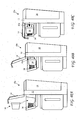
FIG. 2 is a side view of the coffee maker with an open lid allowing placement of a coffee holder according to the present invention inside the coffee maker. -
FIG. 2A is a functional diagram of the coffee maker. -
FIG. 3 is a side view of a first coffee holder according to the present invention. -
FIG. 4 is a cross-sectional side view of the first coffee holder according to the present invention taken along line 4-4 ofFIG. 3 . -
FIG. 5A is a cross-sectional side view of the first coffee holder according to the present invention taken along line 4-4 ofFIG. 3 showing an empty coffee holder with the tamping spring and the bottom tamper according to the present invention. -
FIG. 5B is a cross-sectional side view of the first coffee holder according to the present invention taken along line 4-4 ofFIG. 3 showing the coffee holder with the tamping spring and bottom tamper, a portion of coffee, and the holder lid ready to attach to a holder body according to the present invention. -
FIG. 5C is a cross-sectional side view of the first coffee holder according to the present invention taken along line 4-4 ofFIG. 3 showing the coffee holder with the tamping spring and bottom tamper, the portion of coffee in the coffee holder, and the holder lid ready to attach to the holder body according to the present invention. -
FIG. 5D is a cross-sectional side view of the first coffee holder according to the present invention taken along line 4-4 ofFIG. 3 showing the coffee holder with the tamping spring and bottom tamper, the portion of coffee in the coffee holder, and the holder lid attached to the coffee holder body, according to the present invention. -
FIG. 6 is a top view of the first holder lid. -
FIG. 7A is a side view of a filter paper cup according to the present invention. -
FIG. 7B is a top view of the filter paper cup according to the present invention. -
FIG. 7C is a second embodiment of the filter paper cup with a lid. -
FIG. 8A shows the first coffee holder ready for insertion into the coffee maker. -
FIG. 8B shows the first coffee holder inserted into the coffee maker before tamping the coffee. -
FIG. 8C shows the first coffee holder inserted into the coffee maker after tamping the coffee. -
FIG. 9 is a side view of a second coffee holder. -
FIG. 10 is a cross-sectional side view of the second coffee holder. -
FIG. 11A is a cross-sectional side view of the second coffee holder. -
FIG. 11B is a cross-sectional side view of the second coffee holder taken along line 10-10 ofFIG. 9 showing the coffee holder with the holder lid, tamping spring and top tamper, and a portion of coffee, ready to attach. -
FIG. 11C is a cross-sectional side view of the second coffee holder taken along line 10-10 ofFIG. 9 showing the portion of untamped coffee in the coffee holder, and the holder lid, tamping spring and top tamper, ready to attach to the holder base. -
FIG. 11D is a cross-sectional side view of the second coffee holder taken along line 10-10 ofFIG. 9 showing the portion of coffee in the coffee holder and the tamping spring, top tamper, and the holder lid attached to the coffee holder. -
FIG. 12 is a top view of the second holder lid. -
FIG. 13 is a top view of the bottom tamper. -
FIG. 14A shows the second coffee holder ready for insertion into the coffee maker. -
FIG. 14B shows the second coffee holder inserted into the coffee maker before tamping the coffee. -
FIG. 14C shows the second coffee holder inserted into the coffee maker after tamping the coffee. -
FIG. 15 is a side view of a third coffee holder according to the present invention. -
FIG. 16 is a cross-sectional side view of the third coffee holder according to the present invention taken along line 16-16 ofFIG. 15 . -
FIG. 17A is a cross-sectional side view of the third coffee holder according to the present invention taken along line 16-16 ofFIG. 15 showing the portion of coffee above the coffee holder and the top tamper and the holder lid ready to attach to the coffee holder, according to the present invention. -
FIG. 17B is a cross-sectional side view of the third coffee holder according to the present invention taken along line 16-16 ofFIG. 15 showing the portion of coffee in the coffee holder, and the top tamper and the holder lid ready to attach to the coffee holder, according to the present invention. -
FIG. 17C is a cross-sectional side view of the third coffee holder according to the present invention taken along line 16-16 ofFIG. 15 showing the portion of coffee in the coffee holder, and the bottom tamper, the top tamper, and the holder lid attached to the coffee holder, according to the present invention. -
FIG. 18A shows the third coffee holder ready for insertion into a second coffee maker according to the present invention. -
FIG. 18B shows the third coffee holder inserted into the coffee maker before tamping the coffee. -
FIG. 18C shows the third coffee holder inserted into the coffee maker after tamping the coffee. -
FIG. 19 is a side view of a fourth coffee holder according to the present invention. -
FIG. 20 is a cross-sectional side view of the fourth coffee holder according to the present invention taken along line 20-20 ofFIG. 19 . -
FIG. 21A is a cross-sectional side view of the fourth coffee holder according to the present invention taken along line 20-20 ofFIG. 19 showing the coffee holder with the bottom tamper, a portion of coffee, and the holder lid ready to attach, according to the present invention. -
FIG. 21B is a cross-sectional side view of the fourth coffee holder according to the present invention taken along line 20-20 ofFIG. 19 showing the coffee holder with the bottom tamper, a portion of coffee in the coffee holder, and the holder lid ready to attach, according to the present invention. -
FIG. 21C is a cross-sectional side view of the fourth coffee holder according to the present invention taken along line 20-20 ofFIG. 19 showing the coffee holder with the bottom tamper, a portion of coffee in the coffee holder, and the holder lid attached, according to the present invention. -
FIG. 22A shows the fourth coffee holder ready for insertion into the coffee maker. -
FIG. 22B shows the fourth coffee holder inserted into the coffee maker before tamping the coffee. -
FIG. 22C shows the fourth coffee holder inserted into the coffee maker after tamping the coffee. -
FIG. 23A shows the fourth coffee holder ready for insertion into the coffee maker having a tamping block according to the present invention. -
FIG. 23B shows the fourth coffee holder inserted into the coffee maker having the tamping block before tamping the coffee. -
FIG. 23C shows the fourth coffee holder inserted into the coffee maker having the tamping block after tamping the coffee. -
FIG. 24 is a side view of a fifth coffee holder according to the present invention. -
FIG. 25 is a cross-sectional side view of the fifth coffee holder taken along line 25-25 ofFIG. 24 . -
FIG. 26A is a cross-sectional side view of the fifth coffee holder taken along line 25-25 ofFIG. 24 showing the portion of coffee above the coffee holder body, and the holder lid with the top tamper and tamping spring, ready to attach to the coffee holder body. -
FIG. 26B is a cross-sectional side view of the fifth coffee holder taken along line 25-25 ofFIG. 24 showing the coffee holder with the portion of coffee in the coffee holder, and the holder lid with the top tamper and tamping spring ready to attach to the coffee holder body. -
FIG. 26C is a cross-sectional side view of the fifth coffee holder taken along line 25-25 ofFIG. 24 showing the portion of coffee in the coffee holder, and the holder lid with the top tamper and tamping spring attached to the holder body. -
FIG. 27 is a side view of a sixth coffee holder according to the present invention. -
FIG. 28 is a cross-sectional side view of the sixth coffee holder according to the present invention taken along line 28-28 ofFIG. 27 . -
FIG. 29A is a cross-sectional side view of the sixth coffee holder according to the present invention taken along line 28-28 ofFIG. 27 showing the portion of coffee above the coffee holder, and the holder lid ready to attach to the holder body, according to the present invention. -
FIG. 29B is a cross-sectional side view of the sixth coffee holder according to the present invention taken along line 28-28 ofFIG. 27 showing the portion of coffee in the coffee holder, and the holder lid ready to attach to the holder body, according to the present invention. -
FIG. 29C is a cross-sectional side view of the sixth coffee holder according to the present invention taken along line 28-28 ofFIG. 27 showing the portion of coffee in the coffee holder, and the holder lid attached and tamping the coffee, according to the present invention. -
FIG. 30 is a side view of a seventh coffee holder according to the present invention. -
FIG. 31 is a cross-sectional side view of the seventh coffee holder according to the present invention taken along line 31-31 ofFIG. 30 . -
FIG. 32A is a cross-sectional side view of the seventh coffee holder according to the present invention taken along line 31-31 ofFIG. 30 showing the portion of coffee above the coffee holder, and the holder lid ready to attach to the holder body, according to the present invention. -
FIG. 32B is a cross-sectional side view of the seventh coffee holder according to the present invention taken along line 31-31 ofFIG. 30 showing the portion of coffee in the coffee holder, and the holder lid ready to attach to the holder body, according to the present invention. -
FIG. 32C is a cross-sectional side view of the seventh coffee holder according to the present invention taken along line 31-31 ofFIG. 30 showing the portion of coffee in the coffee holder, and the holder lid attached to the holder body and the coffee tamped between the bottom tamper and spring and the holder lid, according to the present invention. -
FIG. 33 is a side view of an eighth coffee holder according to the present invention. -
FIG. 34A is a cross-sectional side view of the eighth coffee holder taken along line 34-34 ofFIG. 33 showing a portion of coffee for placing inside the coffee holder and the holder lid with an insertable portion and an O-Ring inside the coffee holder for sealing according to the present invention. -
FIG. 34B is a cross-sectional side view of the eighth coffee holder taken along line 34-34 ofFIG. 33 showing the portion of coffee inside the coffee holder and the holder lid with the insertable portion inserted into the coffee holder and cooperating with the O-Ring inside the coffee holder for sealing. -
FIG. 35 is a side view of a ninth coffee holder according to the present invention. -
FIG. 36A is a cross-sectional side view of the ninth coffee holder taken along line 36-36 ofFIG. 35 showing a portion of coffee for placing inside the coffee holder and a holder lid with a threaded portion for screwing inside the holder body for sealing according to the present invention. -
FIG. 36B is a cross-sectional side view of the ninth coffee holder taken along line 36-36 ofFIG. 35 showing the portion of coffee inside the coffee holder and a holder lid with the threaded portion screwed into the holder body and tamping the coffee according to the present invention. -
FIG. 37A shows a third coffee maker having a coffee holder for receiving a portion of coffee and tamping spring according to the present invention for tamping the coffee when the coffee maker lid is closed. -
FIG. 37B shows the third coffee maker with the coffee holder holding the portion of coffee and the tamping spring under the coffee holder according to the present invention for tamping the coffee when the coffee maker lid is closed. -
FIG. 37C shows the third coffee maker with the coffee holder holding the portion of tamped coffee with the coffee maker lid closed for tamping the coffee according to the present invention. -
FIG. 38A shows a third coffee maker having a coffee holder for receiving a portion of coffee and tamping spring attached to the coffee maker lid for tamping the coffee when the coffee maker lid is closed. -
FIG. 38B shows the third coffee maker with the coffee holder holding the portion of untamped coffee for tamping the coffee when the coffee maker lid is closed. -
FIG. 38C shows the third coffee maker with the coffee holder holding the portion of tamped coffee with the coffee maker lid closed to push the tamping spring into the coffee holder for tamping the coffee. -
FIG. 39A shows a fourth coffee maker having a coffee holder for receiving a packet containing untamped coffee, a knife for cutting the packet open, and tamping spring attached to the coffee maker lid according to the present invention for tamping the coffee when the coffee maker lid is closed. -
FIG. 39B shows the fourth coffee maker with the coffee holder holding the packet of untamped coffee according to the present invention for tamping the coffee when the coffee maker lid is closed. -
FIG. 39C shows the fourth coffee maker with the coffee holder holding the packet of tamped coffee with the coffee maker lid closed to push the tamping spring into the coffee holder for tamping the coffee according to the present invention. -
FIG. 40A shows a fifth coffee maker accepting a horizontal coffee holder and tamping spring residing horizontally in a coffee holder cavity according to the present invention for tamping the coffee when the coffee maker lid is closed. -
FIG. 40B shows the fifth coffee maker with the coffee holder residing horizontally in the coffee holder cavity according to the present invention for tamping the coffee when the coffee maker lid is closed. -
FIG. 40C shows the fifth coffee maker with the coffee holder residing horizontally in the coffee holder cavity with the coffee maker lid closed and the coffee holder pushed against the tamping spring for tamping the coffee, according to the present invention. -
FIG. 41 is a side view of a tenth coffee holder with straight walls according to the present invention. -
FIG. 42 is a cross-sectional view of the tenth coffee holder. -
FIG. 43 is a cross-sectional view of the tenth coffee holder. -
FIG. 44 is a side view of an eleventh coffee holder with straight walls according to the present invention. -
FIG. 45 is a cross-sectional view of the eleventh coffee holder taken along line 45-45 ofFIG. 44 showing an empty coffee holder. -
FIG. 46 is a cross-sectional view of the eleventh coffee holder taken along line 45-45 ofFIG. 41 showing a full and tamped coffee holder. -
FIG, 47A is a side view of a top tamper. -
FIG, 47B is a top view of the top tamper. -
FIG, 47C is a side view of a top tamper with a seal according to the present invention. -
FIG, 47D is a top view of the top tamper with a seal. -
FIG. 48 is a perspective view of a filter paper cup with a folding cup lid. -
FIG. 49 is a side view of an twelfth coffee holder with straight walls according to the present invention. -
FIG. 50 is a cross-sectional view of the twelfth coffee holder taken along line 50-50 ofFIG. 49 showing an empty coffee holder. -
FIG. 51A is a cross-sectional view of the twelfth coffee holder taken along line 50-50 ofFIG. 49 showing a lid, coffee, a filter paper cup, above the base, and the coffee holder base. -
FIG. 51B is a cross-sectional view of the twelfth coffee holder taken along line 50-50 ofFIG. 49 showing the lid, above the coffee and the filter paper cup resting in the coffee holder base. -
FIG. 51C is a cross-sectional view of the twelfth coffee holder taken along line 50-50 ofFIG. 49 showing the lid, above the coffee and the filter paper cup resting in the coffee holder base with a filter paper cover folded over the coffee in the filter paper cup. -
FIG. 51D is a cross-sectional view of the twelfth coffee holder taken along line 50-50 ofFIG. 49 showing the lid attached to the base with the coffee and the filter paper cup residing in the coffee holder base with the coffee tamped. -
FIG. 52 is a side view of a thirteenth coffee holder with a releaseable tamping latch according to the present invention. -
FIG. 53 is a cross-sectional view of the thirteenth coffee holder taken along line 53-53 ofFIG. 52 showing an empty coffee holder. -
FIG. 54A is a cross-sectional view of the thirteenth coffee holder taken along line 53-53 ofFIG. 52 showing a lid, coffee, a filter paper cup, above the base, and the coffee holder base, with the tamping latch retaining the bottom tamper. -
FIG. 54B is a cross-sectional view of the thirteenth coffee holder taken along line 53-53 ofFIG. 52 showing the lid, above the coffee and the filter paper cup resting in the coffee holder base, with the tamping latch retaining the bottom tamper. -
FIG. 54C is a cross-sectional view of the thirteenth coffee holder taken along line 53-53 ofFIG. 52 showing the lid, above the coffee and the filter paper cup resting in the coffee holder base with the tamping latch retaining the bottom tamper. -
FIG. 54D is a cross-sectional view of the fourteenth coffee holder taken along line 53-53 ofFIG. 52 showing the lid attached to the base with the coffee and the filter paper cup residing in the coffee holder base with tamping latch released and the coffee tamped. -
FIG. 55 is a side view of a fourteenth coffee holder with a releaseable tamping latch according to the present invention. -
FIG. 56 is a cross-sectional view of the fourteenth coffee holder taken along line 56-56 ofFIG. 55 showing an empty coffee holder. -
FIG. 57A is a cross-sectional view of the fourteenth coffee holder taken along line 56-56 ofFIG. 55 showing a lid, coffee, a filter paper cup, above the base, and,the coffee holder base, with the tamping latch retaining the bottom tamper. -
FIG. 57B is a cross-sectional view of the fourteenth coffee holder taken along line 56-56 ofFIG. 55 showing the lid, above the coffee and the filter paper cup resting in the coffee holder base, with the tamping latch retaining the bottom tamper. -
FIG. 57C is a cross-sectional view of the fourteenth coffee holder taken along line 56-56 ofFIG. 55 showing the lid, above the coffee and the filter paper cup resting in the coffee holder base, with the tamping latch released but just prior to tamping. -
FIG. 57D is a cross-sectional view of the fourteenth coffee holder taken along line 56-56 ofFIG. 55 showing the lid attached to the base with the coffee and the filter paper cup residing in the coffee holder base with tamping latch released and the coffee tamped. -
FIG. 58 is a side view of a fourteenth coffee holder with a releaseable tamping lock according to the present invention. -
FIG. 59 is a cross-sectional view of the fourteenth coffee holder taken along line 59-59 ofFIG. 58 showing an empty coffee holder. -
FIG. 60A is a cross-sectional view of the fourteenth coffee holder taken along line 59-59 ofFIG. 58 showing a lid, coffee, a filter paper cup, above the base, and the coffee holder base, with the tamping lock retaining the bottom tamper. -
FIG. 60B is a cross-sectional view of the fourteenth coffee holder taken along line 59-59 ofFIG. 58 showing the lid, above the coffee and the filter paper cup resting in the coffee holder base, with the tamping lock retaining the bottom tamper. -
FIG. 60C is a cross-sectional view of the fourteenth coffee holder taken along line 59-59 ofFIG. 58 showing the lid, above the coffee and the filter paper cup resting in the coffee holder base prior to tamping. -
FIG. 60D is a cross-sectional view of the fourteenth coffee holder taken along line 59-59 ofFIG. 58 showing the lid attached to the base with the coffee and the filter paper cup residing in the coffee holder base with tamping lock released and the coffee tamped. -
FIG. 61A is a top view of a lock according to the present invention. -
FIG. 61B is a bottom view of a second bottom tamper with cooperates with the tamping lock according to the present invention. -
FIG. 62A shows a pre-packaged brewing material for use in the coffee making according to the present invention. -
FIG. 62B shows a cut away view of the pre-packaged brewing material for use in the coffee making according to the present invention showing the brewing material. -
FIG. 62C shows the pre-packaged brewing material in a coffee holding having a window to expose a bar code. -
FIG. 63D shows the pre-packaged brewing material in the coffee holding having the window to expose a bar code in the cavity of a coffee maker including a bar code reader. -
FIG. 62E shows a coffee holder having the bar code on the coffee holder in the cavity of a coffee maker including the bar code reader -
FIG. 63A is a side view of a filter cup according to the present invention. -
FIG. 63B is a top view of the filter cup according to the present invention. -
FIG. 64 is a side view of multi-mode coffee maker according to the present invention. -
FIG. 65A is a front view of the multi-mode coffee maker according to the present invention with a carafe positioned for receiving a volume of coffee. -
FIG. 65B is a side view of the multi-mode coffee maker according to the present invention with the carafe positioned for receiving a volume of coffee. -
FIG. 66A is a front view of the multi-mode coffee maker according to the present invention with a coffee cup positioned for receiving a volume of coffee. -
FIG. 66B is a side view of the multi-mode coffee maker according to the present invention with the coffee cup positioned for receiving a volume of coffee. -
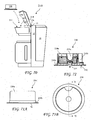
FIG. 67A is a front view of a single cup adapter according to the present invention. -
FIG. 67B is a side view of the single cup adapter according to the present invention. -
FIG. 67C is a top view of the single cup adapter according to the present invention. -
FIG. 67D is a side view of a second single cup adapter according to the present invention. -
FIG. 68 is a cross-sectional view of the single cup adapter according to the present invention taken along line 68-68 ofFIG. 67A . -
FIG. 69A is a side view of a multi- serving coffee holder according to the present invention for use in the multi-mode coffee maker for making several cups of coffee. -
FIG. 69B is a side view of a single-serving coffee holder according to the present invention for use in the multi-mode coffee maker for making one cup of coffee. -
FIG. 70 shows a coffee maker and reuseable cartridge according to the present invention. -
FIG. 71A shows a side view of the reuseable cartridge according to the present invention. -
FIG. 71B shows a top view of the reuseable cartridge according to the present invention. -
FIG. 72 show a cross-sectional view of the reuseable cartridge according to the present invention taken along line 72-72 ofFIG. 71B . -
FIG. 73A shows a side view of a cover of the reuseable cartridge according to the present invention. -
FIG. 73B shows a top view of the cover of the reuseable cartridge according to the present invention. -
FIG. 74 show a cross-sectional view of the cover of the reuseable cartridge according to the present invention taken along line 74-74 ofFIG. 73B . -
FIG. 75A shows a side view of a base of the reuseable cartridge according to the present invention. -
FIG. 75B shows a top view of the base of the reuseable cartridge according to the present invention. -
FIG. 76 show a cross-sectional view of the base of the reuseable cartridge according to the present invention taken along line 76-76 ofFIG. 75B . -
FIG.77A shows a side view of a brewed beverage pod for use in the reuseable cartridge according to the present invention. -
FIG.77B shows a top view of the brewed beverage pod for use in the reuseable cartridge according to the present invention. -
FIG.78A shows a side view of filter paper for use in the reuseable cartridge according to the present invention. -
FIG.78B shows a top view of the filter paper for use in the reuseable cartridge according to the present invention. - Corresponding reference characters indicate corresponding components throughout the several views of the drawings.
- The following description is of the best mode presently contemplated for carrying out the invention. This description is not to be taken in a limiting sense, but is made merely for the purpose of describing one or more preferred embodiments of the invention. The scope of the invention should be determined with reference to the claims.
- A front view of a
coffee 10 maker according to the present invention is shown inFIG. 1A a side view of thecoffee maker 10 is shown inFIG. 1B , and a top view of thecoffee maker 10 is shown inFIG. 1C . Thecoffee maker 10 includes abody 12, an openinglid 14, alid handle 16, awater container 18, adisplay 20, controls 22, aplatform 24 and amouth 12a. Acoffee pitcher 26 rests on theplatform 24 inside themouth 12a and has apitcher lid 28. Thecoffee maker 10 provides a flow of hot water through coffee grounds to produce a coffee drink. The flow of water may be heated by one of any known means, for example, an electrical heating coil or a conductive coating on tubing carrying the water. - A side view of the
coffee maker 10 with anopen lid 14 allowing placement of acoffee holder 30 according to the present invention inside thecoffee maker 10 is shown inFIG. 2 . Thelid 14 includes alid hinge 14a and awater tube 15 carries heated water into thelid 14. Apad 17 resides on a bottom surface of thelid 14 and presses against thecoffee holder 30 when thelid 14 is closed, and in cooperation with other means discloses hereafter, tamps coffee contained in thecoffee holder 30. Anozzle 19 extending down from theclosed lid 14 directs the flow of hot water into thecoffee holder 30. - A functional diagram of the
coffee maker 10 is shown inFIG. 2A . Thepreferred coffee maker 10 includes thewater tank 18,water pump 21, aheater 13,check valve 23 and thenozzle 18. Thepump 21 preferably provides at least one PSI water pressure. Thewater heater 13 may include a heating coil or a resistive coating or any other means for heating water. Thecheck valve 23 limits the water pressure at thenozzle 19 by returning some of the water flow to thewater tank 18. While a thewater pump 21 is a preferred method for providing a flow of water to thenozzle 19, other methods include pressuring the water in thewater tank 18, and a coffee maker using any means to provide a forced flow of water is intending to within the scope of the present invention. - A side view of a
first coffee holder 30a according to the present invention is shown inFIG. 3 and a cross-sectional side view of thefirst coffee holder 30a including aholder body 31, afirst holder lid 32a, abottom tamper 34, and a tampingspring 36 according to the present invention taken along line 4-4 ofFIG. 3 is shown inFIG. 4 . A volume (or coffee holder interior) 38 is provided inside thecoffee holder 30a to receiveloose coffee 41. Apassage 33 in thelid 32a is provided for the nozzle 19 (seeFIG, 2 ). - A cross-sectional side view of the
first coffee holder 30a taken along line 4-4 ofFIG. 3 showing anempty coffee holder 30a with the tampingspring 36 and thebottom tamper 34 ready for filling are shown inFIG. 5A . A cross-sectional side view of thefirst coffee holder 30a taken along line 4-4 ofFIG. 3 showing thecoffee holder 30a with the tampingspring 36 andbottom tamper 34, a portion ofloose coffee 41, and theholder lid 32a ready to attach is shown inFIG. 5B . A cross-sectional side view of thefirst coffee holder 30a taken along line 4-4 ofFIG. 3 showing thecoffee holder 30a with the tampingspring 36 andbottom tamper 34, a portion of coffee in thevolume 38, and theholder lid 32a ready to attach is shown inFIG. 5C . A cross-sectional side view of thefirst coffee holder 30a taken along line 4-4 ofFIG. 3 showing thecoffee holder 30a with the tampingspring 36 andbottom tamper 34, a portion ofloose coffee 41 in thevolume 38, and theholder lid 32a attached to thecoffee holder 30a, is shown inFIG. 5D . - A top view of the
first holder lid 32a showing thepassage 33 provided for the nozzle 19 (seeFIG, 2 ) is shown inFIG. 6 . - A side view of a
filter paper cup 40 according to the present invention is shown inFIG. 7A and a top view of thefilter paper cup 40 is shown inFIG. 7B . Thefilter paper cup 40 includes a bottom 40b,sides 40a, and arim 40c. Therim 40c rests on a top edge of theholder body 31 and is held between the holder cap and body when the cap is placed on the body, thereby preventing or restricting the escape ofcoffee 41 from thecup 40 when hot water flows into thecoffee holder 30a. - A second embodiment of the filter paper cup 40' with a
folding paper lid 40d is shown inFIG. 7C . Thelid 40d of the filter paper cup 40' may be folded over the cup 40' after loose coffee is poured into the cup. Thelid 40d preferably includes aperforation 40e centered on thelid 40d allowing thenozzle 19 to enter and/or inject the hot flow of water into the tampedcoffee 41. - The filter cups may be made from several materials including filter paper, nylon mesh, steel mesh, or any material suitable for filtration.
- The
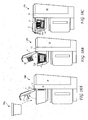
first coffee holder 30a is shown ready for insertion into afirst coffee maker 10a inFIG. 8A , thefirst coffee holder 30a is shown inserted into thecoffee maker 10 before tamping thecoffee 41 inFIG. 8B , and thefirst coffee holder 30a is shown in thecoffee maker 10 after tamping thecoffee 41 inFIG. 8C . The coffee maker includes acavity 11 for accepting the coffee holder and has walls 11a for aligning the coffee holder in the coffee maker. When thelid 14 is closed, thepad 17 on the bottom of thelid 14 and/orarms 25 attached to the bottom of thelid 25, push thecoffee holder 30a down over the tampingspring 36 and thecoffee 41 is tamped between thelid 32a and thebottom tamper 34. Thearms 25 push thecoffee holder 30a down ahead of thenozzle 19 thereby seating thecoffee holder 30a in thecavity 11 for alignment of thenozzle 10 with thepassage 33 in thelid 32a. - A side view of a
second coffee holder 30b according to the present invention is show n inFIG. 9 and a cross-sectional side view of thesecond coffee holder 30b taken along line 10-10 ofFIG. 9 is shown inFIG. 10 . Thecoffee holder 30b includes theholder body 31, asecond holder lid 32b, a tampingspring 36, aspring washer 35a, and atop tamper 35b. - A cross-sectional side view of the
second coffee holder 30b taken along line 10-10 ofFIG. 9 showing anempty coffee holder 30b is shown inFIG. 11A . A cross-sectional side view of thesecond coffee holder 30b taken along line 10-10 ofFIG. 9 showing theholder lid 32b and a loose portion ofcoffee 41 above theempty coffee holder 30b is shown inFIG. 11B . A cross-sectional side view of thesecond coffee holder 30b taken along line 10-10 ofFIG. 9 showing theholder lid 32b above thecoffee holder 30b with the portion ofloose coffee 41 in thecoffee holder 32b is shown inFIG. 11C . A cross-sectional side view of thesecond coffee holder 32b taken along line 10-10 ofFIG. 9 showing the coffee holder with theholder lid 32b attached to thecoffee holder 30b and a portion ofloose coffee 41 in thecoffee holder 30b is shown inFIG. 11D . The tampingspring 36 extends upward out of thecoffee holder 30b for tamping the loose coffee as disclosed hereafter. - A top view of the
second holder lid 32b is shown inFIG. 12 . Theholder lid 32b includes alarger passage 33a allowing passage of the tampingspring 36 through theholder lid 32b. - A top view of the
bottom tamper 34 is shown inFIG. 13 . Thebottom tamper 34 includesperforations 34a to allow coffee drink to pass through thebottom tamper 34. - The
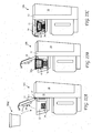
second coffee holder 30b is shown ready for insertion into thecoffee maker 10 inFIG. 14A , thesecond coffee holder 30b is shown inserted into thecoffee maker 10 before tamping thecoffee 41 inFIG. 14B , and thesecond coffee holder 30b is shown in thecoffee maker 10 after tamping thecoffee 41 inFIG. 14C . Thecoffee maker 10 may include along nozzle 19a to reach thetop tamper 35b for "injection" of the heated water into the tamped coffee, but may also include thenozzle 19 and the heated water may pass through thecoffee 41 under the pull of gravity. - A side view of a
third coffee holder 30c according to the present invention is shown inFIG. 16 and a cross-sectional side view of thethird coffee holder 30c taken along line 16-16 ofFIG. 15 is shown inFIG. 16 . Thecoffee holder 30c includes theholder body 31, thesecond holder lid 32b, thebottom tamper 34, and thetop tamper 35b. - A cross-sectional side view of the
third coffee holder 30c taken along line 16-16 ofFIG. 15 showing thecoffee holder 30c with theholder lid 32b, thetop tamper 35b, and a portion of coffee, ready to attach to theholder 31, is shown inFIG. 17A . A cross-sectional side view of the third coffee holder taken along line 16-16 ofFIG. 15 showing thecoffee holder 30c with theholder lid 32b and the top tamper ready to attach, and a portion ofcoffee 41 in the coffee holder, is shown inFIG. 17B . A cross-sectional side view of thethird coffee holder 30c taken along line 16-16 ofFIG. 15 showing the coffee holder with the holder lid and the top tamper attached and a loose portion ofcoffee 41 in the coffee holder is shown inFIG. 17C . Thecoffee holder 30c is configured to use with acoffee make 10b (seeFIGS. 18A-18C ) including apparatus for entering the coffee holder for tamping theloose coffee 41. - The
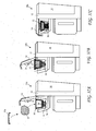
third coffee holder 30c ready for insertion into asecond coffee maker 10b inFIG. 18A , the third coffee,holder 30c is shown residing in thecoffee maker 10b before tamping thecoffee 41 inFIG. 18B , and thethird coffee holder 30c is shown residing in thecoffee maker 10b after tamping thecoffee 41 inFIG. 18C . Thecoffee maker 10b includes the tampingspring 36 attached to thepad 17 on the bottom of thelid 14. When thelid 14 is closed the tampingspring 36 enters thecoffee holder 30c through thelid passage 33a (seeFIG. 12 ) and pushes thetop tamper 35b against thecoffee 41 to tamp thecoffee 41. - A side view of a
fourth coffee holder 30d according to the present invention is shown inFIG. 19 and a cross-sectional side view of thefourth coffee holder 30 taken along line 20-20 ofFIG. 19 is shown inFIG. 20 . Thecoffee holder 30d includes theholder body 31, thefirst holder lid 32a, and thebottom tamper 34. - A cross-sectional side view of the
fourth coffee holder 30d taken along line 20-20 ofFIG. 19 showing the coffee holder with thebottom tamper 34, and a portion ofcoffee 41 and the holder lid ready to attach is shown inFIG. 21A . A cross-sectional side view of thefourth coffee holder 30d taken along line 20-20 ofFIG. 19 showing thecoffee holder 30d with thebottom tamper 34, the portion ofcoffee 41 in thecoffee holder 30d, and theholder lid 32a ready to attach is shown inFIG. 21B . A cross-sectional side view of thefourth coffee holder 30d taken along line 20-20 ofFIG. 19 showing thecoffee holder 30d with thebottom tamper 34, a portion of coffee in thecoffee holder 41, and theholder lid 32a is shown inFIG. 21C . - The
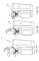
fourth coffee holder 30d ready for insertion into another embodiment of thesecond coffee maker 10b inFIG. 22A , thefourth coffee holder 30d is shown residing in thecoffee maker 10b before tamping thecoffee 41 inFIG. 22B , and thefourth coffee holder 30d is shown residing in thecoffee maker 10b after tamping thecoffee 41 inFIG. 22C . Thecoffee maker 10b may include the tampingspring 36 residing in the bottom of thecoffee holder cavity 11. When thelid 14 is closed, thepad 17 pushed thecoffee holder 30d down over the tampingspring 36 and the tampingspring 36 enters thecoffee holder 30c through the bottom of theholder body 31 and pushes thebottom tamper 34 against thecoffee 41 to tamp thecoffee 41. - The
fourth coffee holder 30d ready for insertion into another embodiment of thesecond coffee maker 10b inFIG. 23A , thefourth coffee holder 30d is shown residing in thecoffee maker 10b before tamping thecoffee 41 inFIG. 23B , and thefourth coffee holder 30d is shown residing in thecoffee maker 10b after tamping thecoffee 41 inFIG. 23C . Thecoffee maker 10b may include a resilientsolid block 42 residing in the bottom of thecoffee holder cavity 11. When thelid 14 is closed, thepad 17 pushed thecoffee holder 30d down over the resilientsolid block 42 and the resilientsolid block 42 enters thecoffee holder 30c through the bottom of theholder body 31 and pushes thebottom tamper 34 against thecoffee 41 to tamp thecoffee 41. - A side view of a
fifth coffee holder 30e according to the present invention is shown inFIG. 24 and a cross-sectional side view of thefifth coffee holder 30e taken along line 25-25 ofFIG. 24 is shown inFIG. 25 . Thefifth coffee holder 30e includes theholder body 31, theholder lid 32b, the tampingspring 36 and thetop tamper 35b attached to theholder lid 32a. - A cross-sectional side view of the
fifth coffee holder 30e taken along line 25-25 ofFIG. 24 showing thecoffee holder 30e with a portion ofcoffee 41, and theholder lid 32b with thetop tamper 35b and tampingspring 36 attached, above theholder body 31, is shown inFIG. 26A . A cross-sectional side view of thefifth coffee holder 30e taken along line 25-25 ofFIG. 24 showing the coffee holder with the portion ofcoffee 41 in the coffee holder, and theholder lid 32b with thetop tamper 35b and tampingspring 36 attached, above theholder body 31, is shown inFIG. 26B . A cross-sectional side view of thefifth coffee holder 30e taken along line 25-25 ofFIG. 24 showing thecoffee holder 30e with the portion ofcoffee 41 in thecoffee holder 30e, and theholder lid 32b with thetop tamper 35b and tampingspring 36 attached to theholder base 31 is shown inFIG. 26D . The tampingspring 36 andtop tamper 35b tamp thecoffee 41 to provide a tamped coffee when theholder lid 32b is attached to theholder base 31. - A side view of a
sixth coffee holder 30f according to the present invention is shown inFIG. 27 and a cross-sectional side view of thesixth coffee holder 30f taken along line 28-28 ofFIG. 27 is shown inFIG. 28 . Thesixth coffee holder 30f includes theholder body 31 and athird holder lid 32c. Thethird holder lid 32c includes a recessed portion 32' which reaches into the interior of thesixth coffee holder 30f. The recessed portion 32' is preferably a solid resilient material. - A cross-sectional side view of the
sixth coffee holder 30f taken along line 28-28 ofFIG. 27 showing thesixth coffee holder 30f with a portion ofcoffee 41, and theholder lid 32c, above theholder body 31, is shown inFIG. 29A . A cross-sectional side view of thesixth coffee holder 30f taken along line 28-28 ofFIG. 27 showing the coffee holder with the portion ofcoffee 41 in the coffee holder, and theholder lid 32c above theholder body 31, is shown inFIG. 29B . A cross-sectional side view of thesixth coffee holder 30f along line 28-28 ofFIG. 27 showing thesixth coffee holder 30f with the portion ofcoffee 41 in thecoffee holder 30e, and theholder lid 32e attached to theholder base 31 is shown inFIG. 26D . A cushion 32' tamps thecoffee 41 to provide a tamped coffee when theholder lid 32e is attached to theholder base 31. The cushion 32' is preferably made from a resilient material to cushion the tamping of fhe loose coffee. - A side view of a
seventh coffee holder 30g according to the present invention is shown inFIG. 30 and a cross-sectional side view of theseventh coffee holder 30g taken along line 31-31 ofFIG. 30 is shown inFIG. 31 . Theseventh coffee holder 30g includes theholder body 31, theholder lid 32b, the tampingspring 36, and thebottom tamper 34 inside theholder base 31. - A cross-sectional side view of the
seventh coffee holder 30g taken along line 31-31 ofFIG. 30 showing theseventh coffee holder 30g with a portion ofcoffee 41 and theholder lid 32a above theholder body 31, and with thebottom tamper 34 and tampingspring 36 inside theholder base 31, is shown inFIG. 26A . A cross-sectional side view of theseventh coffee holder 30g taken along line 31-31 ofFIG. 30 showing the coffee holder with the portion ofcoffee 41 in thefilter paper 40 in theholder base 31 resting on thebottom tamper 34 supported by the tampingspring 36, and theholder lid 32a above theholder body 31, is shown inFIG. 26B . A cross-sectional side view of theseventh coffee holder 30g taken along line 31-31 ofFIG. 30 showing theseventh coffee holder 30g with the portion ofcoffee 41 in thecoffee holder 30e, and theholder lid 32a attached to theholder base 31, is shown inFIG. 26D . The tampingspring 36 andbottom tamper 34 tamp thecoffee 41 upward against thetamper lid 32a to provide a tamped coffee when theholder lid 32a is attached to theholder base 31. - A side view of an
eighth coffee holder 30h according to the present invention is shown inFIG. 33 , a cross-sectional side view of theeighth coffee holder 30h taken along line 34-34 ofFIG. 33 showing a portion ofcoffee 41 for placing inside the coffee holder and afourth holder lid 32d with an insertable portion and an O-Ring 50 inside the coffee holder for sealing is shown inFIG. 34A , and a cross-sectional side view of the eighth coffee holder taken along line 34-34 ofFIG. 33 showing the portion ofcoffee 41 inside thecoffee holder 30h and theholder lid 32d with the insertable portion inserted into thecoffee holder base 31a is shown inFIG. 34B . Thefilter paper 40 extends up above the O-ring 50 and the O-Ring 50 cooperates with theholder lid 32d to sandwich the top edge of thefilter paper 40 for sealing thefilter paper 40 to reduce or prevent thecoffee 41 from escaping when the flow of hot water is provided to thecoffee holder 30h. Theholder base 31a is preferably cylindrical but may also be conical in shape. - A side view of a
ninth coffee holder 30i according to the present invention is shown inFIG. 35 , a cross-sectional side view of theninth coffee holder 30i taken along line 36-36 ofFIG. 35 showing a portion ofcoffee 41 for placing inside the coffee holder and afifth holder lid 32e with a threaded portion for screwing inside theholder base 31b for sealing is shown inFIG. 36A , and a cross-sectional side view of theninth coffee holder 30i taken along line 36-36 ofFIG. 35 showing the portion ofcoffee 41 inside the coffee holder and theholder lid 32e with the threaded portion screwed into the coffee holder and tamping thecoffee 41 is shown inFIG. 36B . The threads both provide tamping and sealing the coffee to reduce or prevent thecoffee 41 from escaping when the flow of hot water is provided to thecoffee holder 30h. Theholder base 31b is preferably cylindrical to facilitate having internal threads, and at least the threaded portion is preferably cylindrical. - A
third coffee maker 10c having acoffee holder 30 according to the present invention for receiving a portion of coffee and a tampingspring 36 for tamping the coffee is shown inFIG. 37A , thethird coffee maker 10c with thecoffee holder 30 holding the portion ofcoffee 41 is shown inFIG. 37B , and thethird coffee maker 10c with thecoffee holder 30 holding the portion ofcoffee 41 with thecoffee maker lid 14 closed for tamping thecoffee 41 is shown inFIG. 37C . When thelid 14 is closed, thepad 17 pushes thecoffee holder 30 down and the tampingspring 36 enters the bottom of thecoffee holder 30 to tamp thecoffee 41. While attaching thelid 32a to theholder 30 is preferred in order to prevent coffee grounds from escaping theholder 30, thecoffee maker 10c may also be used without thelid 32a and thepad 17 may serve to seal thecoffee 41 in theholder 30. In this instance, thecoffee maker lid 14 serves as a coffee holder lid. - A
third coffee maker 10c having a coffee holder for receiving a portion of coffee and tampingspring 36 attached to thecoffee maker lid 14 according to the present invention for tamping thecoffee 41 when thecoffee maker lid 14 is closed is shown inFIG. 38A , the third coffee maker with thecoffee holder 30 holding the portion ofcoffee 41 is shown inFIG. 38B , and thethird coffee maker 10c with thecoffee holder 30 holding the portion ofcoffee 41 with thecoffee maker lid 14 closed to push the tampingspring 36 into thecoffee holder 30 for tamping thecoffee 41 is shown inFIG. 38C . - A
fourth coffee maker 10d having athird holder base 31c for receiving apacket 41a containing untamped coffee, aknife 50 for cutting thepacket 41a open, and tampingspring 36 under theholder base 31c according to the present invention for tamping the coffee when the coffee maker lid is closed is shown inFIG. 39A , thefourth coffee maker 10d with theholder base 31c holding thepacket 41a of untamped coffee is shown inFIG. 39B , and fourth coffee maker with theholder base 31c holding the packet of tampedcoffee 41c with thecoffee maker lid 14 closed to push the holder base down over the tampingspring 36 for tamping the coffee is shown inFIG. 39C . Thecoffee maker 10d includes a somewhatpointed nozzle 19b to puncture thepacket 41 a to provide the flow of hot water to the tamped coffee in thepacket 41 a. Known coffee packets include internal filters to allow a flow of hot water through the packet to make the coffee drink while preventing coffee grounds from escaping. The cut in thepacket 41a made by theknife 50 allows the coffee drink to escape from the packet while filter material in thepacket 41a prevent coffee grounds from escaping. The tampingspring 36 may also be attached to thelid 14 as inFIGS. 38A -38C . - The
packet 41a may be an air tight pod containing coffee in filter paper and positioning the knife on the side of theholder base 31 c results in less likelihood of theknife 50 cutting the filter paper. Thepacket 41a is preferably air tight to maintain coffee freshness and may be plastic, metal foil, or other air tight material which is sufficiently flexible to allow the coffee contained in thepacket 41a to be tamped. Alternatively, theknife 50 may be eliminated when thepacket 41 a is configured to burst under pressure to expose the coffee, for example, when the coffee maker tamps the coffee, thepacket 41a also bursts. In one embodiment,filter paper 41 is inserted into theholder base 31 c without theknife 50, and thepacket 41 a bursts during compacting to release the coffee into the filter paper. - Known coffee makers use a sealed cup or capsule having a somewhat ridged cup with a foil cover. Such cups might be compressible and used in the
coffee maker 10d, however, a similar cup or capsule having a less ridged cup which may be compressed in thecoffee maker 10d are more suitable for use in thecoffee maker 10d to allow tamping of the coffee contained in the cup or capsule. - A
fifth coffee maker 10e for horizontally receiving thecoffee holder 30 is shown inFIG. 40A , the fifth coffee maker with thecoffee holder 30 residing in the coffee maker is shown inFIG. 40B , and the fifth coffee maker with thecoffee maker lid 14 closed and the tampingspring 36 entering thecoffee holder 30 for tamping thecoffee 41 is shown inFIG. 40C . Thefifth coffee maker 10d may alternatively include a tamping spring entering the coffee holder top, or a resilient solid block pushed into thecoffee holder 30 to tamp the coffee. Preferably, ahorizontal ram 42a is actuated when thelid 14 is closed and pushed thecoffee holder 30 against thespring 36 to tamp the coffee. Thehorizontal ram 42a may actuated by an electrical solenoid, by pressure, or by mechanical levers connected to thelid 14. Thefifth coffee maker 10e may further include any of the features described above for other embodiments of the coffee maker according to the present invention and may be configured to use any of the coffee holders described above according to the present invention. - A side view of a
tenth coffee holder 30j with straight walls according to the present invention is shown inFIG. 41 , and a cross-sectional view of thetenth coffee holder 30j taken along line 42-42 ofFIG. 41 showing an empty coffee holder is shown inFIG. 42 . Thecoffee holder 30j provides straight cylindrical inside walls allowing a better fit between thetop tamper 35b and the inside walls to reduce or eliminatecoffee 41 escaping past thetop tamper 35b during tamping. - A cross-sectional view of the
tenth coffee holder 30j taken along line 42-42 ofFIG. 41 showing a full and tamped coffee holder is shown inFIG. 43 . The tampingspring 36 has been pushed down by thelid 32b to tamp thecoffee 41. - A side view of an
eleventh coffee holder 30k with straight walls according to the present invention is shown inFIG. 44 , a cross-sectional view of theeleventh coffee holder 30k taken along line 45-45 ofFIG. 44 showing an empty coffee holder is shown inFIG. 45 , and a cross-sectional view of theeleventh coffee holder 30k taken along line 45-45 ofFIG. 41 showing a full and tamped coffee holder. As with thecoffee holder 30j, thecoffee holder 30k provides straight cylindrical inside walls allowing a better fit between thelid 32f and the inside walls to reduce or eliminatecoffee 41 escaping past thelid 32f during tamping. Thelid 32f may be used with or without thetop tamper 35b. - A side view of a
top tamper 35b is shown inFIG. 47A and a top view of the top tamper 35B is shown inFIG. 47B . A side view of atop tamper 35b' with aseal 60 according to the present invention is shown inFIG. 47C and a top view of thetop tamper 35b' with theseal 60 is shown inFIG. 47D . In some instances, for example with a very fine ground coffee, an amount of coffee may escape past thetop tamper 35b. In such instances, a user may prefer to use thetop tamper 35b' with theseal 60 to reduce or eliminate the escape of the coffee. - A perspective view of a filter paper cup 40' with a
folding cup lid 40d is shown inFIG. 48 (also seeFIG. 7C ). Thecup lid 40d may be folded over therim 40c to reduce or prevent coffee from escaping during tamping of subsequent processing. Thelid 40d may also include aperforation 40e centered on thelid 40d allowing thenozzle 19 to enter and/or inject the hot flow of water into the tampedcoffee 41, but in some embodiments, thelid 40d does not include theperforation 40e. The filter paper cup 40' may be used in the coffee containers described herein, and may able be used in a coffee machine having a cavity for receiving the filter paper cup 40'. While the cup 40' is preferably made from filter paper, the cup may also be made from a reusable mech. - A side view of an
twelfth coffee holder 301 with straight walls according to the present invention is shown inFIG. 49 , and a cross-sectiorial view of thetwelfth coffee holder 301 taken along line 50-50 ofFIG. 49 showing an empty coffee holder is shown inFIG. 50 . Thetwelfth coffee holder 301 includes a straight walled base and the tamping spring below the coffee, and additionally uses a filter paper cup 40' with thefolding lid 40d. - A cross-sectional view of the
twelfth coffee holder 301 taken along line 50-50 ofFIG. 49 showing thelid 32a,coffee 41, the filter paper cup 40' withlid 40d, above thecoffee holder base 31a is shown inFIG. 51A , a cross-sectional view of thetwelfth coffee holder 301 taken along line 50-50 ofFIG. 49 showing thelid 32a, above thecoffee 41 and the filter paper cup 40' resting in thecoffee holder base 31a is shown inFIG. 51B , a cross-sectional view of thetwelfth coffee holder 301 taken along line 50-50 ofFIG. 49 showing thelid 32a, above thecoffee 41 and the filter paper cup 40' resting in thecoffee holder base 31 a with thefilter paper cover 40d folded over thecoffee 41 in the filter paper cup 40' is shown inFIG. 51C , and a cross-sectional view of thetwelfth coffee holder 301 taken along line 50-50 ofFIG. 49 showing thelid 32a attached to thebase 31a with thecoffee 41 and the filter paper cup 40' residing in thecoffee holder base 31a with thecoffee 41 tamped is shown inFIG. 51D . In embodiments with thecoffee 41 partially exposed above the base 31 a, somecoffee 41 may escape during tamping. Using the filter paper cup 40' having the fold overpaper lid 40d reduces or eliminates such escape ofcoffee 41 and additionally provides a drum like taut surface for consistent puncturing - A side view of a
thirteenth coffee holder 30m with areleaseable tamping latch 64 according to the present invention is shown inFIG. 52 and a cross-sectional view of thethirteenth coffee holder 30m taken along line 53-53 ofFIG. 52 showing an empty coffee holder is shown inFIG. 53 . Thelatch 64 is held in a latched position by a spring loadedlever 62 on the exterior of thebase 31a. - A cross-sectional view of the
thirteenth coffee holder 30m taken along line 53-53 ofFIG. 52 showing thelid 32a,coffee 41, thefilter paper cup 40, above thebase 31a, and thecoffee holder base 31a, with the tampinglatch 64 retaining thebottom tamper 34 is shown inFIG. 54A , a cross-sectional view of thethirteenth coffee holder 30m taken along line 53-53 ofFIG. 52 showing thelid 32a above thecoffee 41 and thefilter paper cup 40 resting in thecoffee holder base 31a, with the tampinglatch 64 retaining thebottom tamper 34 is shown inFIG. 54B , a cross-sectional view of thethirteenth coffee holder 30m taken along line 53-53 ofFIG. 52 showing thelid 32a, above thecoffee 41 and thefilter paper cup 40 resting in thecoffee holder base 31a with the tampinglatch 64 retaining thebottom tamper 34 is shown inFIG. 54C , and a cross-sectional view of thefourteenth coffee holder 30m taken along line 53-53 ofFIG. 52 showing thelid 32a attached to thebase 31a with thecoffee 41 and thefilter paper cup 40 residing in thecoffee holder base 31a with tampinglatch 64 released and thecoffee 41 tamped is shown inFIG. 54D . Thelever 62 thus holds thelatch 64 until thelever 62 is pushed to release thelatch 62 to release thebottom tamper 34 to tamp thecoffee 41. - A side view of a
fourteenth coffee holder 30n with areleaseable tamping latch 64 according to the present invention is shown inFIG. 55 and a cross-sectional view of the fourteenth coffee holder taken along line 56-56 ofFIG. 55 showing an empty coffee holder is shown inFIG. 56 . Thelever 62 holds thelatch 64 until thearm 66 attached to thelid 32g pushes thelever 62 to release thelatch 64. - A cross-sectional view of the
fourteenth coffee holder 30n taken along line 56-56 ofFIG. 55 showing thelid 32g,coffee 41,and thefilter paper cup 40, above thecoffee holder base 31a, with the tampinglatch 64 retaining thebottom tamper 34 is shown inFIG 57A , a cross-sectional view of thefourteenth coffee holder 30n taken along line 56-56 ofFIG. 55 showing thelid 32g above thecoffee 41 and thefilter paper cup 40 resting in thecoffee holder base 31a, with the tampinglatch 64 retaining thebottom tamper 34 is shown inFIG. 57B , a cross-sectional view of thefourteenth coffee holder 30n taken along line 56-56 ofFIG. 55 showing thelid 32g, above the coffee 41and thefilter paper cup 40 resting in thecoffee holder base 31a with the tampinglatch 64 released but just prior to tamping (the bottom tamper has been released but has not moved upward against the coffee 41) is shown inFIG. 57C , and a cross-sectional view of thefourteenth coffee holder 30n taken along line 56-56 ofFIG. 55 showing thelid 32g attached to the base with thecoffee 41 and thefilter paper cup 40 residing in the coffee holder base31 a with tampinglatch 64 released and thecoffee 41 tamped is shown inFIG. 57D . Thelever 62 thus holds thelatch 64 until thelever 62 is pushed by thearm 66 to release thelatch 64 to release thebottom tamper 34 to tamp thecoffee 41. - A side view of a fourteenth coffee holder 30o with a releaseable tamping lock according to the present invention is shown in
FIG. 58 and a cross-sectional view of the fourteenth coffee holder 30o taken along line 59-59 ofFIG. 58 showing an empty coffee holder is shown inFIG. 59 . The coffee holder 30o includes a tampinglock 70 which engages a second bottom tamper 34' to hold the second bottom tamper in a down position for filling the coffee holder with coffee and releases the bottom tamper 34' to be pushed upwards by the tampingspring 36 to tamp the coffee after theholder lid 32b is attached to thebase 31a. - A cross-sectional view of the fourteenth coffee holder 30o taken along line 59-59 of
FIG. 58 showing alid 32b,coffee 41, afilter paper cup 40, above thecoffee holder base 31, with the tampinglock 70 retaining the bottom tamper 34' is shown in FIG.FIG. 60A , cross-sectional view of the fourteenth coffee holder taken along line 59-59 ofFIG. 58 showing the lid, above the coffee and the filter paper cup resting in the coffee holder base, with the tamping latch retaining the bottom tamper 34' is shown in FIG.FIG. 60B , a cross-sectional view of the fourteenth coffee holder taken along line 59-59 ofFIG. 58 showing the lid, above the coffee and the filter paper cup resting in the coffee holder base prior to tamping is shown inFIG. 60A , and a cross-sectional view of the fourteenth coffee holder taken along line 59-59 ofFIG. 58 showing thelid 32b attached to thebase 31a with thecoffee 41 and thefilter paper cup 41 residing in thecoffee holder base 31a with tamping lock released and the coffee tamped is shown inFIG. 60D . - A top view of a tamping
lock 70 according to the present invention is shown inFIG. 61A and a bottom view of a second bottom tamper 34' which cooperates with the tampinglock 70 according to the present invention is shown inFIG. 61B . The tampinglock 70 includesteeth 72 which are inserted between and turned to engagelips 74 on the bottom of the bottom tamper 34' to hold the bottom tamper in the down position for filling the coffee holder 30o withcoffee 41. After the coffee holder 30o is filled with coffee and theholder lid 32b attached, the tamping lock is twisted to release thebottom tamper 32b to tamp the coffee. - A pre-packaged
rimmed brewing pod 41b for use in the coffee making according to the present invention is shown inFIG.62A , a cut away view of thepre-packaged brewing material 41a for use in the coffee making showing thepod 41b is shown inFIG. 62B , and acoffee holder 30p having awindow 77 is shown inFig. 62C . Thepod 41b is generally suitable for use in any of thecoffee holders 30a-30o described above. Thepod 41b further includes anidentification feature 76 to provide information to the coffee maker to properly brew thespecific brewing material 41 in thepod 41b. The rim of thepod 41b is captured by the lid of thecoffee holder 30p thereby providing a drum like (or taut) surface for consistent puncturing by thepointed nozzle 19b (seeFIGS. 39A-39C ). - The pre-packaged
rimmed brewing pod 41b is shown residing in acoffee holder 30p inFIG. 62D with theidentification feature 76 cooperating with asensor 78 residing in or near thecavity 11 of the coffee maker, and acoffee holder 30q having theidentification feature 76 affixed to thecoffee holder 30d is shown inFIG. 62E with theidentification feature 76 cooperating with thesensor 78 residing in or near thecavity 11 of the coffee maker. Thewindow 77 provides visual cooperation between theidentification feature 76 andsensor 78 when necessary. - The
identification feature 76 may be visual (for example any feature which may be read or a bar code), a readable magnetic strip, a Radio Frequency Identification (RFID), or any feature able to contain information and provide that information to a reader. Theidentification feature 76 may be read by asensor 78 appropriately positioned in thecavity 11 of the coffee maker. Theidentification feature 76 may be on any surface of thepre-packaged brewing material 41 a and in the instance of avisual identification feature 76, thewindow 77 may be positioned on thecoffee holder 30p and the sensor may be positioned in thecavity 11 to correspond with the position of thevisual identification feature 76. Awindow 77 is generally not required for a magnetic orRF identification feature 76 and the location of the correspondingsensor 78 generally only need be sufficiently near to theidentification feature 76. - In another embodiment, a
sensor 78 resides on the exterior of the coffee maker. A bulk brewing material container, a pre packaged pod, a coffee holder, a recipe book, or any apparatus carrying an identification feature, may be swept past the sensor or held against or near the sensor, to provide brewing information to the coffee maker. - A side view of a
filter cup 80 according to the present invention is shown inFIG. 63A and a top view of thefilter cup 80 is shown inFIG. 63B . Thefilter cup 80 includes aring 84 made a of a material sufficiently strong to hold shape in the proposed use.Filter material 82 is attached to thering 84. Thefilter cup 80 is insertable into the coffee holder and in many embodiments is a replacement for thefilter paper cup 40. - A side view of
multi-mode coffee maker 100 according to the present invention is shown inFIG. 64 . Themulti-mode coffee maker 100 allows the user to easily make a single cup of coffee or several cups of coffee. Themulti-mode coffee maker 100 includes manually operatedcontrols 102 for selecting a volume of water for a single cup of coffee or to fill a carafe, residing in themouth 114 of themulti-mode coffee maker 100. Thecontrols 102 may also allow selection of a large or small cup of coffee, and of hot water only. Alternatively, themulti-mode coffee maker 100 may detect the presence of asingle cup adapter 118 and limit the volume of coffee produced to an amount for a single cup, for example as an override if a user accidentally selects a volume of coffee too large for a single cup. - A spout/
drip valve 104 releases the desired amount of coffee into a carafe or coffee positioned on aplatform 24, and a drip valve actuator (or valve lever) 106 is actuateable to open and close the spout/drip valve 104. In other examples, the drip valve actuator may be pneumatic, hydraulic, or electric, and may be any mechanical link which opens the spout/drip valve 104. The spout/drip valve 104 may further be manually opened by a user. For example, the spout/drip valve 104 is opened by placing the multi-cup brewedcoffee container 26 in thecoffee maker 100 and openable for use of the single cup brewedcoffee container 116 by either a mechanical or electrically operated actuator or by positioning of thesingle cup adapter 118 for use of the single cup. - In another embodiment the spout/
drip valve 104 is opened by the positioning of a single cup adapter into position for use of a single cup in the coffee maker, for example by an arm on the single cup adapter cooperating with a lever connected to the spout/drip valve, by an arm residing at the rear of the mouth, the single cup adapter pushing against the arm to open the spout/drip valve, or by any mechanical or electrical apparatus connected to the spout/drip valve and actuated by positioning the single cup adapter to use a single cup in the coffee maker. In still another embodiment the flow of brewed coffee is controlled by turning thepump 21 on and off, by controlling a boiler, or by controlling a valve preventing the flow of water to the coffee holder. - A
hot plate 108 is recessed on the top surface of theplatform 24 and the recess is larger than the footprint of the multi-cup brewed coffee container (or carafe) 26 allowing contact with thehot plate 108 for keeping a carafe at a minimum temperature. Apassage 110 allows afinger 120 of a single cup adapter 118 (seeFIG. 67B ) to engage aswitch 112 to turn off thehot plate 108 when thesingle cup adapter 118 is in use. - A front view of the
multi-mode coffee maker 100 with acarafe 26 residing on theplatform 24 for receiving a selected volume of coffee is shown inFIG. 65A and a side view of themulti-mode coffee maker 100 with thecarafe 26 positioned for receiving a selected volume of coffee is shown inFIG. 65B . The top edge of thecarafe 26 pushes thevalve lever 106 upward opening the spout/drip valve 104 to allow the selected volume of coffee to flow into thecarafe 26. - A front view of the
multi-mode coffee maker 100 with a coffee cup (or single cup brewed coffee container) 116 residing on asingle cup adapter 118 for receiving the selected volume of coffee is shown inFIG. 66A and a side view of themulti-mode coffee maker 100 with the coffee cup residing on thesingle cup adapter 118 for receiving the selected volume of coffee is shown inFIG. 66B . Thesingle cup adapter 118 includes an upward reachingarm portion 118b (seeFIG.67B ) which pushes thevalve lever 106 upward opening the spout/drip valve 104 to allow the selected volume of coffee to flow into thecoffee cup 116. - A front view of a
single cup adapter 118 according to the present invention is shown inFIG. 67A , a side view of thesingle cup adapter 118 is shown inFIG. 67B , a top view of thesingle cup adapter 118 is shown inFIG. 67C , and a cross-sectional view of thesingle cup adapter 118 taken along line 68-68 ofFIG. 67A is shown inFIG. 68 . Thesingle cup adapter 118 includes abase portion 118a which includes asingle cup platform 129 for supporting thecoffee cup 116 and a drip basin (or tray) 124 for catching and holding drops from the spout/drip valve 104. Agrill 126 resides over thedrip basin 124 and thecoffee cup 116 rests on thegrill 126. Anarm portion 118b reaches up and anangled surface 128 at the top of thearm portion 118b cooperates with thevalve lever 106 to open the spout/drip valve 104 when thesingle cup adapter 118 is positioned in thecoffee maker 100 In another embodiment, the drip tray may be integrated into thecoffee maker 100 and may pivot or slide into position under thecoffee cup 116, for example, thesingle cup adapter 118 may have an open side or rear that the drip tray slides or pivots into. - A
downward protrusion 122 on the bottom of thebase portion 118a fits into a recess in theplatform 24 to correctly position thesingle cup adapter 118 in themouth 114 of thecoffee maker 100, and to resist easy detachment of thesingle cup adapter 118 from thecoffee maker 100. A rearward reachingfinger 120 enters thepassage 110 to actuate the switch 112 (seeFIG. 64 ) to turn off the hot plate when thesingle cup adapter 118 is attached to thecoffee maker 100. Thefinger 120 and switch 112 are one example of a means for turning off thehot plate 108 when thesingle cup adapter 118 is attached to thecoffee maker 100. Other means include a magnet switch detecting the presence of thehot plate 108 in thesingle cup adapter 118 by the proximity of a magnet and piece of magnetically attractive metal or a second magnet, a switch in the platform, or even a manual switch, and a coffee maker according to the present invention with any switch for turning off the hot plate is intended to come within the scope of the present invention. - A side view of a second single cup adapter 118' according to the present invention is shown in
FIG. 67D . The single cup adapter 118' is a compact version of thesingle cup adapter 118 and does not include thearm portion 118b. The single cup adapter 118' provide single serving functions through the insertion of the rearward reachingfinger 120 into thecoffee maker 100. These functions include shutting off the hot plate 108 (seeFIG. 64 ), opens the open the spout/drip valve 104 to release brewed beverage, setting thecoffee maker 100 to the single serving mode (limits the beverage to one to sixteen ounces). - A side view of a multi-serving
dry coffee holder 130a according to the present invention for use in themulti-mode coffee maker 100 for making several cups of brewed coffee is shown inFIG. 69A and a side view of a single-servingdry coffee holder 130b according to the present invention for use in themulti-mode coffee maker 100 for making one cup of coffee is shown inFIG. 69B . A variety ofdry coffee holders 30a-30o and means for containing and tamping dry coffee in a coffee maker are disclosed inFIGS. 3 though 63B, and amulti-mode coffee maker 100 including any of the coffee holders disclosed herein; or any other coffee holder, is intended to come within the scope of the present invention. - A
coffee maker 210 andreuseable cartridge 230 according to the present invention are shown inFIG. 70 , a side view of thereuseable cartridge 230, is shown inFIG. 71B , a top view of thereuseable cartridge 230 is shown inFIG. 71B , and a cross-sectional view of the reuseable cartridge according to the present invention taken along line 72-72 ofFIG. 71B . Thereuseable cartridge 230 comprises acover 230a and abase 230b. Thecover 230a is removeable from the base 230b to fill thereuseable cartridge 230 withbrewing material 41. Generally, thereuseable cartridge 230 is filled by pouringloose coffee 41 into thebase 230b. Once filled with thebrewing material 41, thereuseable cartridge 230 is inserted into thecavity 211 of thecoffee maker 210 and thelid 214 is closed. Thelid 214 of thecoffee maker 210 generally includes aprojections 214a which engagesrecesses 236a of the cover 236 to urge thereuseable cartridge 230 into position in thecavity 211. A flow of water 232 (generally a flow of heated water) enters thereuseable cartridge 230, passes through thebrewing material 41, and a flow of brewedbeverage 234 exits thereuseable cartridge 230. An theidentification feature 76 resides on a bottom surface providing the benefits described inFIGS. 62A-62E above. Such identification feature 76 may be attached other positions on the exterior of thereuseable cartridge 230. - A side view of a
cover 230a of thereuseable cartridge 230 is shown inFIG. 73A , a top view of thecover 230a of thereuseable cartridge 230 is shown inFIG 73B , and a cross-sectional view of thecover 230a of thereuseable cartridge 230 taken along line 74-74 ofFIG. 73B . The cover includesrecesses - A side view of a base 230b of the
reuseable cartridge 230 is shown inFIG.75A , a top view of thebase 230b is shown inFIG. 75B , and a cross-sectional view of thebase 230b taken along line 76-76 ofFIG. 75B is shown inFIG.76 . Thebase 230b includesentry port 238a for the flow ofwater 232, andexit port 238b for the flow of brewedbeverage 234. The flow ofwater 232 enters thebase 230a and much climb over thewall 240 to reach the interior of the 244 of thebase 230b. Forcing the flow ofwater 232 over thewall 240 causes the flow ofwater 232 to pass through thebrewing material 41, thereby producing a rich brewed beverage. Afilter 242 resides over theexit port 238b to prevent thebrewing material 41 from escaping into a cup of brewed beverage. - A side view of a brewed
beverage pod 250 for use in thereuseable cartridge 230 according to the present invention is shown inFIG. 77A and a top view of the brewedbeverage pod 250 is shown inFIG. 77B . The brewedbeverage pod 250 is shaped to conform reasonable well to the interior of the 244 of thebase 230b and includes apassage 250a for therecess 236a in thecover 230a.. - A side view of a
filter paper 252 for use in thereuseable cartridge 230 according to the present invention is shown inFIG. 78A and a top view of thefilter paper 252 is shown inFIG. 78B . Thefilter paper 252 is shaped to conform reasonable well to the interior of the 244 of thebase 230b and includes apassage 252a for therecess 236a in thecover 230a.. Thefilter paper 252 includes a filter cover 252'. After inserting thefilter paper 252 into thebase 230b and filling thefilter paper 252 withbrewing material 41, the filter cover 252' is folded over thebrewing material 41 and thecover 230a is pressed onto thebase 230b. Arim 253 of thefilter paper 252, and matching rim 253' of the filter cover 252' may be sandwiched between thecover 230a andbase 230b to securely hold the filter cover 252' on thefilter paper 252 to retain thebrewing material 41 in thefilter paper 252. - While the present invention is described above as placing loose coffee in a coffee holder, the invention may also be practiced by placing prepackaged coffee, for example coffee pods, into the coffee holder. Further, while the coffee holder is generally described as having a snap on lid, a screw on lid may also be used, and in general the various elements of different embodiments described above may be mixed to provide new embodiments and such new embodiments are intended to come within the scope of the present invention.
- Further, many embodiments are described as including a coffee chamber comprising a filter paper cup. In many cases, a filter cup made of nylon mesh or metal mesh is equally suitable, and any coffee holder or combination of coffee maker and coffee holder including a filter chamber which holds coffee and allows the coffee to be tamped as described above is intended to come within the scope of the present invention regardless of the specific filter material. Further, those skilled in the art will recognize that the features of the various embodiments of the present invention disclosed herein may be combined to provide various combinations. All of such combinations are intended to come with the scope of the present invention.
- The present invention finds industrial applicability in the field of beverage makers.
- While the invention herein disclosed has been described by means of specific embodiments and applications thereof, numerous modifications and variations could be made thereto by those skilled in the art without departing from the scope of the invention set forth in the claims.
Claims (15)
- A self-tamping coffee holder (30) comprising:a coffee holder base (31) having an open top for receiving a removable filtering material cup (40) into a holder cavity (38) inside the coffee holder; the filtering material cup configured to receive a portion of untamped coffee (41);a holder lid (32) configured to engage and close the open top of the coffee holder base after receiving the filtering material cup and the portion of untamped coffee;a tamper (34) residing in the bottom of the coffee holder base configured to tamp the portion of untamped coffee.
- The self-tamping coffee holder of claim 1, wherein the tamper comprises a bottom tamper (34) configured to reside in the bottom of the coffee holder base below the untamped coffee, the bottom tamper configured to tamp the portion of coffee upwards against the holder lid.
- The self-tamping coffee holder of claim 2, wherein the bottom tamper comprises: a spring (36) residing in a bottom portion of the coffee holder base; and a tamper supported by the spring, the spring and tamper configured to tamp the filtering material containing the portion of untamped coffee against the holder lid.
- The self-tamping coffee holder of claim 1, wherein the filtering material cup (40) is a filter paper cup (40).
- The self-tamping coffee holder of claim 4, wherein the coffee holder base (31) is a frustoconical coffee holder base having a smaller bottom and larger top.
- The self-tamping coffee holder of claim 4, wherein the filter paper cup (40) includes a rim (40c) configured to trap between the coffee holder (30) and holder lid (32).
- The self tamping coffee holder of claim 6, wherein the filter paper cup (40) includes a cover having a cover rim overlapping the rim (40c) of the filter paper cup, the cover rim and the rim of the filter paper cup are configured to trap between the coffee holder (30) and holder lid (32).
- The self-tamping coffee holder of claim 7, wherein the cover rim is configured to be held taut between the coffee holder (30) and holder lid (32) to provide a drum-like surface for consistent puncturing by a nozzle (19) of a coffee maker.
- The self tamping coffee holder of claim 8, wherein the cover rim is hingedly attached to the filter paper cup (40).
- the self-tamping coffee holder of claim 9, wherein the holder lid (32) includes an opening (33) configured for passage of the nozzle (19) of the coffee maker.
- The self-tamping coffee holder of claim 10, wherein the opening (33) in the holder lid (32) is permanently open.
- The self-tamping coffee holder of claim 1, wherein the filtering material cup (40) is a mesh cup.
- The self-tamping coffee holder of claim 12, wherein the mesh cup is a metal mesh cup.
- A self-tamping coffee holder of claim 11, wherein the self-tamping coffee holder (30) is frustoconically shaped and the rim (40c) of the filter paper cup (40) configured to receive a portion of untamped coffee reaches radially outward from a top edge of the filter paper cup
- A method for using a self-tamping coffee holder (30), the method comprising: placing a filter paper cup (40) inside a frustoconical shaped coffee holder base (31), the coffee holder base comprising:a smaller diameter bottom;a larger diameter top;a holder cavity (38) inside the coffee holder base; andthe top open for receiving a removable filter paper cup (40);positioning a rim (40c) reaching radially outward from a top edge of the filter paper cup over the top of the coffee holder base;depositing a portion of untamped coffee (41) into the filter paper cup;folding a hingedly attached cover of the filter paper cup over the rim of the filter paper cup;pushing a holder lid (32) downward against the filter paper cup and the hingedly attached cover containing the portion of untamped brewing material downward into the holder base depressing a spring (36) and tamper (34) attached to the spring residing in the bottom of the holder base;sandwiching the rim of the filter paper cup and an overlapping outside edge of the hingedly attached cover of the filter paper cup between the holder lid and the holder base;holding the filter paper cover taut between the holder lid and holder base to provide a drum like surface for consistent puncturing by a nozzle (19) of a coffee maker (10), the holder lid including a permanently open passage (33) for the nozzle;engaging a holder lid to, the holder base.
Applications Claiming Priority (4)
| Application Number | Priority Date | Filing Date | Title |
|---|---|---|---|
| US12/610,181 US8621981B2 (en) | 2009-10-30 | 2009-10-30 | Coffee maker |
| US12/620,584 US8291812B2 (en) | 2009-10-30 | 2009-11-17 | Self tamping coffee holder |
| US12/762,262 US9844292B2 (en) | 2009-10-30 | 2010-04-16 | Coffee maker with multi and single cup modes |
| PCT/US2010/054896 WO2011053890A2 (en) | 2009-10-30 | 2010-10-30 | Coffee maker with multi and single cup modes |
Publications (3)
| Publication Number | Publication Date |
|---|---|
| EP2493357A2 EP2493357A2 (en) | 2012-09-05 |
| EP2493357A4 EP2493357A4 (en) | 2013-06-19 |
| EP2493357B1 true EP2493357B1 (en) | 2015-09-02 |
Family
ID=43923037
Family Applications (1)
| Application Number | Title | Priority Date | Filing Date |
|---|---|---|---|
| EP10827590.0A Active EP2493357B1 (en) | 2009-10-30 | 2010-10-30 | Coffee maker with multi and single cup modes |
Country Status (6)
| Country | Link |
|---|---|
| US (6) | US9844292B2 (en) |
| EP (1) | EP2493357B1 (en) |
| CN (1) | CN102695442B (en) |
| CA (1) | CA2779263C (en) |
| HK (1) | HK1175969A1 (en) |
| WO (1) | WO2011053890A2 (en) |
Families Citing this family (42)
| Publication number | Priority date | Publication date | Assignee | Title |
|---|---|---|---|---|
| US11337543B2 (en) | 2007-07-13 | 2022-05-24 | Adrian Rivera | Brewing material holder |
| US10722066B2 (en) * | 2010-12-04 | 2020-07-28 | Adrian Rivera | Windowed single serving brewing material holder |
| US9242790B2 (en) * | 2007-07-13 | 2016-01-26 | Adrian Rivera | Method for tamping brewing material using a self tamping single serving brewing material holder |
| US11832755B2 (en) | 2007-07-13 | 2023-12-05 | Adrian Rivera | Brewing material container for a beverage brewer |
| US8167006B1 (en) * | 2010-04-29 | 2012-05-01 | Jason Mathis | Automated baby formula dispenser |
| SG185493A1 (en) | 2010-05-12 | 2012-12-28 | Nestec Sa | Capsule, system and method for preparing a beverage by centrifugation |
| SG189393A1 (en) * | 2010-11-11 | 2013-05-31 | Nestec Sa | Capsule, beverage production machine and system for the preparation of a nutritional product |
| ES2593432T3 (en) * | 2010-11-12 | 2016-12-09 | Lorenzo Giacomin | Machine powered by AC and / or DC voltage to prepare espresso coffee and other infusions and drinks |
| US9101243B2 (en) | 2011-05-26 | 2015-08-11 | The Richards Corporation | Universal espresso maker |
| NL2007126C2 (en) * | 2011-07-18 | 2013-01-21 | Barista Technology B V | Ground coffee pressing device. |
| WO2013032331A1 (en) * | 2011-09-02 | 2013-03-07 | Koninklijke Douwe Egberts B.V. | Beverage filter assembly |
| WO2013032330A1 (en) * | 2011-09-02 | 2013-03-07 | Koninklijke Douwe Egberts B.V. | Beverage filter cartridge |
| US10080459B2 (en) | 2011-11-09 | 2018-09-25 | La Vit Technology Llc | Capsule-based system for preparing and dispensing a beverage |
| US10034570B2 (en) | 2011-11-09 | 2018-07-31 | LaVit Technology LLC | Capsule based system for preparing and dispensing a beverage |
| WO2013093218A1 (en) * | 2011-12-23 | 2013-06-27 | FRYDMAN, Philippe | Assembly for preparing a beverage by extracting the contents of a capsule |
| US8911811B2 (en) * | 2011-12-27 | 2014-12-16 | Whirlpool Corporation | Method of operating a coffee maker |
| US20130344205A1 (en) | 2012-06-22 | 2013-12-26 | Touch Coffee and Beverages, LLC. | Beverage brewing system |
| US9320382B2 (en) | 2013-07-15 | 2016-04-26 | La Vit Technology Llc | Capsule based system for preparing and dispensing a beverage |
| ITMO20130295A1 (en) * | 2013-10-17 | 2015-04-18 | Sarong Spa | DRINKING MACHINE FOR DRINKS |
| US10136754B2 (en) * | 2014-01-17 | 2018-11-27 | Keurig Green Mountain, Inc. | Beverage machine cartridge holder |
| US9173519B2 (en) | 2014-01-17 | 2015-11-03 | Keurig Green Mountain, Inc. | Method and apparatus for beverage carafe detection |
| US9295357B2 (en) | 2014-01-17 | 2016-03-29 | Keurig Green Mountain, Inc. | Apparatus for cup and carafe beverage production |
| US9504348B2 (en) | 2014-03-11 | 2016-11-29 | Starbucks Corporation | Cartridge ejection systems and methods for single-serve beverage production machines |
| US20150257586A1 (en) * | 2014-03-11 | 2015-09-17 | Starbucks Corporation Dba Starbucks Coffee Company | Single-serve beverage production machine |
| US9439532B2 (en) | 2014-03-11 | 2016-09-13 | Starbucks Corporation | Beverage production machines with multi-chambered basket units |
| US10188238B2 (en) | 2014-03-11 | 2019-01-29 | Starbucks Corporation | Beverage production machines and methods with tamping assembly |
| US9433316B2 (en) | 2014-04-15 | 2016-09-06 | Sunbeam Products, Inc. | Hot beverage brewer for multiple volumes |
| EP3142527B1 (en) * | 2014-05-12 | 2018-03-28 | Nestec S.A. | Beverage preparation unit with safety valve |
| CN106231962A (en) | 2014-05-12 | 2016-12-14 | 雀巢产品技术援助有限公司 | Beverage preparation units |
| WO2015174967A1 (en) * | 2014-05-13 | 2015-11-19 | Joe Pod Ventures, Llc | Single serve brewing system for drip coffee makers |
| JP6674729B2 (en) * | 2014-05-29 | 2020-04-01 | タイガー魔法瓶株式会社 | Ingredient extraction type beverage production device and container stand |
| WO2016029355A1 (en) * | 2014-08-26 | 2016-03-03 | Top Electric Appliances Industrial Ltd. | A coffee capsule filler appliance |
| DE102014019778B4 (en) * | 2014-12-12 | 2020-03-12 | Bernhard Schultes | Device for tampering coffee |
| DE102014225764B4 (en) * | 2014-12-12 | 2017-03-30 | Bernhard Schultes | Device for tamping coffee |
| US10342377B2 (en) | 2015-06-16 | 2019-07-09 | Starbucks Corporation | Beverage preparation systems with adaptable brew chambers |
| US10602874B2 (en) | 2015-06-16 | 2020-03-31 | Starbucks Corporation Dba Starbucks Coffee Company | Beverage preparation systems with brew chamber access mechanisms |
| US9968217B2 (en) | 2015-06-16 | 2018-05-15 | Starbucks Corporation | Beverage preparation systems with brew chamber securing mechanisms |
| US9962031B2 (en) * | 2015-10-30 | 2018-05-08 | Adrian Rivera | Brewing chamber with dynamic water dispersion |
| US9883766B2 (en) * | 2015-11-20 | 2018-02-06 | Pepsico, Inc. | Beverage dispenser systems and methods |
| CA3041722A1 (en) | 2016-11-09 | 2018-05-17 | Pepsico, Inc. | Carbonated beverage makers, methods, and systems |
| USD873596S1 (en) * | 2018-05-09 | 2020-01-28 | Hamilton Beach Brands, Inc. | Coffeemaker |
| US11805934B1 (en) | 2020-10-21 | 2023-11-07 | Adrian Rivera | Brewing material lid and container for a beverage brewer |
Family Cites Families (262)
| Publication number | Priority date | Publication date | Assignee | Title |
|---|---|---|---|---|
| US1743925A (en) | 1929-05-18 | 1930-01-14 | Richard F Krause | Drip-coffee maker |
| US1871590A (en) * | 1930-05-03 | 1932-08-16 | Annunzio Ugo V D | Apparatus for extracting juice from fruits |
| US2433815A (en) | 1935-04-24 | 1947-12-30 | Laforge Pierre Charl Nicephore | Apparatus for pressing fruit |
| FR948422A (en) | 1947-06-09 | 1949-08-01 | Device for preparing filter coffee in pressure vessels of the espresso type | |
| US3022411A (en) | 1958-09-16 | 1962-02-20 | Nat Presto Ind | Beverage maker |
| US3119682A (en) | 1959-08-05 | 1964-01-28 | Ciba Ltd | Herbicidal composition containing as the active ingredient a phenyl ether urea |
| US3199682A (en) * | 1960-12-27 | 1965-08-10 | Nat Can Corp | Coffee maker can |
| US3120170A (en) * | 1961-06-08 | 1964-02-04 | Garte Mathew | Coffee making device |
| US3316388A (en) | 1961-06-14 | 1967-04-25 | Sunbeam Corp | Automatically controlled immersible electric coffee maker |
| US3224360A (en) | 1961-06-14 | 1965-12-21 | Sunbeam Corp | Automatic coffee maker |
| US3115822A (en) * | 1962-01-11 | 1963-12-31 | Advance Engineering Company | Beverage brewing apparatus |
| US3136241A (en) * | 1962-10-12 | 1964-06-09 | Westinghouse Electric Corp | Coffee maker with combination cover |
| BE638951A (en) * | 1962-12-31 | |||
| US3269298A (en) * | 1963-10-16 | 1966-08-30 | John F Grundmann | Fluid flow control apparatus |
| US3336857A (en) | 1965-05-27 | 1967-08-22 | Corning Glass Works | Invertible drip coffee maker |
| CH459495A (en) | 1965-09-21 | 1968-07-15 | Moerlini Gilbert | Device for preparing a coffee infusion |
| US3384004A (en) | 1965-11-26 | 1968-05-21 | Hill Shaw Company | Coffeemaker |
| US3405630A (en) | 1966-11-28 | 1968-10-15 | Scovill Manufacturing Co | Coffee maker |
| US3530787A (en) * | 1967-03-14 | 1970-09-29 | Frank R Litterio | Apparatus for preparing and dispensing freshly brewed coffee |
| US3446624A (en) * | 1967-07-28 | 1969-05-27 | William David Luedtke | Disposable coffee drip brewer |
| US3403617A (en) | 1967-11-20 | 1968-10-01 | Universal Oil Prod Co | Apparatus for piercing containers for use in beverage producing machines |
| US3478670A (en) * | 1968-06-28 | 1969-11-18 | Westinghouse Electric Corp | Air operated single cup coffee brewer |
| US3607297A (en) * | 1969-03-13 | 1971-09-21 | Osvaldo Fasano | Method for producing beverages |
| US3583308A (en) * | 1969-08-29 | 1971-06-08 | Willie L Williams | Apparatus for heating and dispensing water for coffee makers |
| US3592126A (en) | 1969-12-19 | 1971-07-13 | Gen Electric | Coffeemaker filter |
| US3599557A (en) * | 1970-05-19 | 1971-08-17 | Virgilio Leal | Coffee-brewing assembly for espresso coffeemaking device |
| US3695168A (en) | 1970-06-02 | 1972-10-03 | George H Van Brunt | Drip coffee maker |
| DE2129070B2 (en) * | 1971-06-11 | 1974-08-29 | Joh. Jacobs & Co Gmbh, 2800 Bremen | Device for the automatic preparation of a coffee drink from coffee portions fed to a brewing station via a conveyor |
| US3844206A (en) * | 1971-11-19 | 1974-10-29 | R Weber | Infusor apparatus |
| US3757670A (en) | 1972-02-10 | 1973-09-11 | Sunbeam Corp | Expresso coffeemaker |
| US3878772A (en) | 1974-03-01 | 1975-04-22 | Nordskog Co Inc | Reusable coffee maker container |
| CH597813A5 (en) * | 1974-10-02 | 1978-04-14 | Hagezet Ag | |
| US3948157A (en) | 1975-03-10 | 1976-04-06 | Refreshment Machinery Incorporated | Brew cup filter |
| US3958502A (en) | 1975-05-16 | 1976-05-25 | Cory Food Services, Inc. | Beverage brewer |
| US4052318A (en) | 1976-07-08 | 1977-10-04 | Krebs Bonnie E | Mesh coffee filter |
| US4086848A (en) | 1977-01-26 | 1978-05-02 | Hahn Harry L | Device for brewing individual cups of coffee |
| USD255313S (en) | 1977-08-30 | 1980-06-10 | U.S. Philips Corporation | Coffee filter |
| US4143590A (en) | 1978-02-21 | 1979-03-13 | Sam Kasakoff | Coffee maker assembly |
| DE2808215C3 (en) | 1978-02-25 | 1980-12-04 | Kabel- Und Metallwerke Gutehoffnungshuette Ag, 3000 Hannover | Device for filtering liquids |
| IT7821703V0 (en) * | 1978-05-03 | 1978-05-03 | Illy Caffe S P A | MACHINE FOR MAKING A CUP OF COFFEE. |
| DE2850959C2 (en) | 1978-11-24 | 1986-06-19 | Apura Gmbh, 6502 Mainz-Kostheim | Containers for collecting and compacting waste |
| US4164644A (en) * | 1978-08-07 | 1979-08-14 | Courtesy Interstate Corporation | Portable electrical heating unit with automatic cutoff |
| US4300442A (en) * | 1980-04-28 | 1981-11-17 | Societe D'assistance Technique Pour Produits Nestle Sa | Coffee maker |
| DK162369C (en) * | 1982-07-19 | 1992-03-23 | Mars G B Ltd | METHOD AND DISPENSES FOR THE PREPARATION OF AN INFUSIONAL BEVERAGE |
| NL8300213A (en) | 1983-01-20 | 1984-08-16 | Douwe Egberts Tabaksfab | DEVICE FOR PREPARING HOT DRINKS. |
| US4510853A (en) | 1983-04-20 | 1985-04-16 | Tokyo Shibaura Denki Kabushiki Kaisha | Coffee making apparatus |
| DE3400567C3 (en) | 1984-01-10 | 1994-07-28 | Krups Fa Robert | Electrically operated espresso machine |
| US4603621A (en) | 1984-07-23 | 1986-08-05 | Bloomfield Industries, Inc. | Beverage-making device |
| WO1986002816A1 (en) | 1984-11-05 | 1986-05-22 | Matsushita Electric Industrial Co., Ltd. | Electric coffee heater |
| DE8535291U1 (en) | 1985-12-14 | 1986-02-06 | Melitta-Werke Bentz & Sohn, 4950 Minden | coffee machine |
| US4703687A (en) | 1986-06-05 | 1987-11-03 | Wei Yung Kuan | Coffee maker |
| US4721835A (en) | 1986-10-06 | 1988-01-26 | Helmut Welker | Microwave brewing cup |
| US4704954A (en) | 1986-11-10 | 1987-11-10 | Mollenhoff David V | Drip coffee maker |
| US4739697A (en) | 1987-05-04 | 1988-04-26 | Bloomfield Industries, Inc. | Brew chamber with filter spacer |
| IT1210382B (en) | 1987-06-23 | 1989-09-14 | Zanussi Grandi Impianti Spa | AUTOMATIC MACHINES FOR THE PREPARATION OF COFFEE OR SIMILAR. |
| US4832845A (en) | 1987-12-15 | 1989-05-23 | Thomas Hendretti | Permanent coffee filter |
| US4800089A (en) | 1988-03-14 | 1989-01-24 | Scott George W | Packet with internal filter for coffee machines |
| US4986172A (en) | 1988-05-02 | 1991-01-22 | Hunnicutt Jr Clyde J | Beverage brewing apparatus |
| US4858523A (en) | 1988-07-12 | 1989-08-22 | Edward Helbling | Automatic infusion-beverage apparatus |
| US4967648A (en) | 1988-07-12 | 1990-11-06 | Edward Helbling | Automatic infusion-beverage apparatus |
| US5072660A (en) | 1988-07-12 | 1991-12-17 | Edward Helbling | Automatic infusion-beverage apparatus |
| US5000082A (en) | 1988-07-27 | 1991-03-19 | Food Equipment Technologies Company, Inc. | Beverage maker and method of making beverage |
| DE3829417C2 (en) | 1988-08-31 | 1996-08-08 | Krups Fa Robert | Electrically operated device for preparing infusion drinks such as coffee, tea or the like. |
| US4867880A (en) | 1988-10-14 | 1989-09-19 | D.J. Incorporated | Brewing device |
| US5108768A (en) * | 1988-11-25 | 1992-04-28 | So Peter K L | Cartridge for beverage making |
| DE8815627U1 (en) | 1988-12-16 | 1989-02-16 | Robert Krups Stiftung & Co Kg, 5650 Solingen, De | |
| US4865737A (en) | 1989-01-03 | 1989-09-12 | Mcmichael John R | Filter support for disposable coffee filters |
| US5012059A (en) | 1989-05-10 | 1991-04-30 | Donald C. Riddle | Appliance for heating water by microwave power |
| JP2978184B2 (en) | 1989-10-06 | 1999-11-15 | 株式会社日立製作所 | Control rule creation device |
| US5012629A (en) | 1989-10-11 | 1991-05-07 | Kraft General Foods, Inc. | Method for producing infusion coffee filter packs |
| US5028328A (en) | 1989-11-30 | 1991-07-02 | Long Joseph F | Controlled pore size coffee filter |
| US5401328A (en) | 1990-01-03 | 1995-03-28 | Henkel Kommanditgesellschaft Auf Aktien | Arrangement for cleaning mechanical devices, small parts and/or electronic switching units |
| EP0468080B1 (en) | 1990-07-27 | 1994-12-28 | Societe Des Produits Nestle S.A. | Method for extracting open coffee-cartridges, coffee-cartridge and extraction device for implementing this method |
| ES2047777T3 (en) | 1990-07-27 | 1994-03-01 | Nestle Sa | INSERT ADAPTABLE TO A CARTRIDGE HOLDER. |
| DE69022847T2 (en) | 1990-07-27 | 1996-03-14 | Nestle Sa | Brewing device for closed portion packs. |
| DE69002945T2 (en) | 1990-07-27 | 1994-01-20 | Nestle Sa | Method for brewing closed portion packs and device for carrying out this method. |
| CA2054113A1 (en) | 1990-10-30 | 1992-05-01 | Robert F. Smith | Coffee brewing method |
| US5190653A (en) | 1990-10-30 | 1993-03-02 | Kraft General Foods, Inc. | Coffee brewer filtration device |
| US5562941A (en) | 1990-10-31 | 1996-10-08 | Levy; Ehud | Process for improving the taste of beverages by reducing bitterness |
| US5243164A (en) | 1990-12-14 | 1993-09-07 | Gee Associates | Beverage maker |
| US5109763A (en) * | 1990-12-17 | 1992-05-05 | G. A. Morris Enterprises, Inc. | Oil filter crusher unit |
| US5897899A (en) | 1991-05-08 | 1999-04-27 | Nestec S.A. | Cartridges containing substances for beverage preparation |
| US5633026A (en) | 1991-07-05 | 1997-05-27 | The Procter & Gamble Company | Tea filter pack for automatic brewers |
| ES2079523T3 (en) | 1991-07-05 | 1996-01-16 | Nestle Sa | CARTRIDGE EXTRACTION DEVICE ADAPTABLE TO ANY EXPRESS MACHINE. |
| US5298267A (en) | 1991-07-05 | 1994-03-29 | The Procter & Gamble Company | Coffee filter pack |
| US5171457A (en) | 1991-07-10 | 1992-12-15 | Pamela A. Acuff | Method of handling wet coffee grounds in filter cups |
| US5233914A (en) * | 1991-08-01 | 1993-08-10 | English Philip H | In-car coffee maker |
| US5123335A (en) * | 1991-08-05 | 1992-06-23 | Pullen Aselu | Coffee maker apparatus |
| DE4130446A1 (en) | 1991-09-13 | 1993-03-25 | Braun Ag | BREW BEVERAGE MACHINE |
| US5265517A (en) | 1991-10-09 | 1993-11-30 | Industria Columbiana De Electronicos Y Electrodomesticos, Incelt S.A. Of Carrera | Method and apparatus for brewing coffee |
| CA2083324A1 (en) | 1992-02-03 | 1993-08-04 | Shirdan J. Grykiewicz | Brew basket |
| DE4212288A1 (en) | 1992-04-11 | 1993-10-14 | Braun Ag | Brewing device for a household espresso machine |
| US5325765A (en) * | 1992-09-16 | 1994-07-05 | Keurig, Inc. | Beverage filter cartridge |
| US5840189A (en) * | 1992-09-16 | 1998-11-24 | Keurig, Inc. | Beverage filter cartridge |
| US6118933A (en) * | 1992-11-25 | 2000-09-12 | Roberson; Danny J. | Apparatus and method for preparing infant formula from powder with dispensing and filtering means |
| US5267506A (en) | 1993-01-13 | 1993-12-07 | Zhihua Cai | Apparatus for automatic coffee brewing |
| US5335589A (en) * | 1993-08-02 | 1994-08-09 | Yerves Jr Kenneth A | Multiple beverage dispenser |
| CH685667A5 (en) * | 1993-10-18 | 1995-09-15 | Max Hugentobler | Filter unit for making filter coffee. |
| US5363745A (en) | 1993-11-30 | 1994-11-15 | Lin Hsiang Cheng | Beverage vessel with magnetic lid |
| IT233916Y1 (en) | 1994-01-17 | 2000-02-16 | Zanarini Gianfranco | SINGLE-DOSE FILTER FOR HOT PREPARATION OF AN INFUSION |
| US5406882A (en) | 1994-03-30 | 1995-04-18 | Shaanan Holdings Inc. | Brewer |
| US5605710A (en) | 1994-06-06 | 1997-02-25 | Marathon Partners | Single cup disposable coffee brewing device |
| DE4436080A1 (en) | 1994-10-10 | 1996-04-11 | Braun Ag | Brewing device for a household espresso machine |
| US5424083A (en) | 1994-10-24 | 1995-06-13 | Lozito; Michael C. | Self contained disposable coffee brewing device |
| US5531152A (en) | 1995-01-05 | 1996-07-02 | Grimac Royal Falcon Corp. | Platen assembly for coffee maker using pre-dosaged coffee filter packets |
| US5635233A (en) | 1995-01-09 | 1997-06-03 | Levinson; Melvin L. | Methods for preparing a coffee, tea and milk beverage |
| US5463932A (en) | 1995-01-19 | 1995-11-07 | Olson; Allen W. | Coffee maker |
| US5676041A (en) * | 1995-02-03 | 1997-10-14 | Appliance Development Corp. | Coffee brewing apparatus |
| FR2730621B1 (en) | 1995-02-21 | 1997-05-09 | Levi Mario | DEVICE FOR FIXING A FILTER HOLDER CUP UNDER THE CUP HOLDER OF A COFFEE MACHINE |
| FR2731337B1 (en) | 1995-03-06 | 1997-05-09 | Levi Mario | DEVICE ALLOWING THE USE, ON A COFFEE MACHINE, OF GROUND COFFEE OR PRE-PACKAGED COFFEE CAKES |
| US5669287A (en) | 1995-07-20 | 1997-09-23 | Harry D. Jefferson | Coffee and tea brewing apparatus and system |
| IT1277108B1 (en) | 1995-12-19 | 1997-11-04 | Opem Srl | MACHINE FOR PRODUCING, FROM CONTINUOUS FILM, ROUND AND NON-ROUND COFFEE PODS FOR AUTOMATIC ESPRESSO COFFEE MACHINES |
| US5865094A (en) | 1996-02-13 | 1999-02-02 | Kealy; Michael J. | Filtered beverage maker |
| US6065609A (en) | 1996-04-17 | 2000-05-23 | Lake; Reginald W. | Beverage brewing kit |
| FR2749745B1 (en) * | 1996-06-17 | 1998-08-07 | Seb Sa | COFFEE MACHINE OPERATING WITH DIFFERENT TYPES OF CONTAINERS |
| CA2184298C (en) | 1996-08-27 | 1998-08-18 | Yvan St-Gelais | Permanent filter coffeemaker |
| AU6187298A (en) | 1997-03-03 | 1998-09-22 | John J. Soughan | Coffee flavoring means and method |
| ATE179314T1 (en) * | 1997-03-13 | 1999-05-15 | Braun Ag | FILTRATION DEVICE, FILTER ELEMENT AND METHOD FOR PRODUCING THE FILTER ELEMENT USED FOR PRODUCING BREWED DRINKS |
| US5865095A (en) * | 1997-03-20 | 1999-02-02 | Conair Corporation | Coffee grinder and maker |
| US5924563A (en) | 1997-04-10 | 1999-07-20 | Hamilton Beach/Proctor-Silex, Inc. | Packaging arrangement for filter products |
| US5829340A (en) * | 1997-04-15 | 1998-11-03 | Yang; Po-Han | Coffee maker |
| USD407602S (en) | 1997-06-23 | 1999-04-06 | Cafe 98 Industries Limited | Coffee brew basket |
| US5887510A (en) | 1997-08-06 | 1999-03-30 | Porter; Mark D. | Device for making coffee |
| US5895672A (en) | 1998-01-13 | 1999-04-20 | Cooper; Barry Patrick Wesley | Product and process for preparing a tea extract |
| US6231909B1 (en) | 1998-02-04 | 2001-05-15 | Melvin L. Levinson | Fat-homogenizer, beverage-frother, kitchen appliance to prepare coffee, tea, milk, egg, soy, and rice foodstuff |
| US6727484B2 (en) * | 1998-04-16 | 2004-04-27 | Nini Policappelli | Making beverages and food in a microwave oven |
| DE29813791U1 (en) * | 1998-08-01 | 1998-10-15 | Riensch & Held | Permanent filter for the preparation of tea in jugs or cups |
| US6662955B1 (en) | 1998-08-11 | 2003-12-16 | Food Equipment Technologies Company Inc. | Beverage ingredient filter and assembly |
| US20020005367A1 (en) | 1998-11-25 | 2002-01-17 | Steve Terry Zelson | Coffee filter holder |
| US6253662B1 (en) | 1998-12-21 | 2001-07-03 | Steve Terry Zelson | Coffee machine |
| US6079315A (en) | 1999-01-19 | 2000-06-27 | Keurig, Inc. | Beverage filter cartridge holder |
| IT1310537B1 (en) * | 1999-02-22 | 2002-02-18 | Simac Vetrella Spa | MACHINE FOR THE PRODUCTION OF ESPRESSO COFFEE |
| US6227102B1 (en) | 1999-04-27 | 2001-05-08 | John C. K. Sham | Automatic coffee maker with grinder |
| US6164191A (en) * | 1999-06-04 | 2000-12-26 | Pacific Cornetta Inc. | Single serving beverage maker |
| USD431423S (en) * | 1999-07-15 | 2000-10-03 | Cobbs Manufacturing Company | Collapsible cup holder |
| US6136352A (en) * | 1999-07-20 | 2000-10-24 | The Topps Company, Inc. | Sanitary novelty candy product |
| NL1012847C2 (en) | 1999-08-17 | 2001-02-20 | Sara Lee De Nv | Coffee preparation device. |
| US6250209B1 (en) | 1999-09-13 | 2001-06-26 | Bunn-O-Matic Corporation | Brewer filter support |
| US6517880B2 (en) | 2000-01-14 | 2003-02-11 | Kx Industries, L.P. | Beverage brewing system and method for using same |
| US6589577B2 (en) | 2000-02-18 | 2003-07-08 | Keurig, Inc. | Disposable single serve beverage filter cartridge |
| US6645537B2 (en) | 2000-02-18 | 2003-11-11 | Keurig, Incorporated | Beverage filter cartridge |
| US6607762B2 (en) | 2000-02-18 | 2003-08-19 | Keurig, Incorporated | Disposable single serve beverage filter cartridge |
| USD454433S1 (en) | 2000-03-17 | 2002-03-19 | Concert Industries Ltd. | Embossed non-woven fabric |
| US6555074B1 (en) | 2000-04-05 | 2003-04-29 | Earle C. Sweet | Apparatus for making herbal extracts using percolation |
| US6263781B1 (en) | 2000-04-06 | 2001-07-24 | Juanito B. Calagui | Cup receptacle with filter insert and its associated method of use |
| US6499388B2 (en) | 2000-06-14 | 2002-12-31 | Fianara Interational B. V. | Coffee machine for brewing coffee power pre-packed in a cartridge |
| US6440256B1 (en) | 2000-06-20 | 2002-08-27 | Keurig, Incorporated | Method of forming and inserting filter elements in cup-shaped containers |
| CZ20012835A3 (en) | 2000-08-30 | 2002-04-17 | Fianara International B. V. | Coffee machine for brewing coffee powder pre-packed in a cartridge |
| CN100407971C (en) | 2000-09-28 | 2008-08-06 | 松下电器产业株式会社 | Kettle for boiling coffee |
| US20020048621A1 (en) | 2000-10-06 | 2002-04-25 | Boyd David D. | Encoded coffee packet |
| EP1203554A1 (en) | 2000-11-03 | 2002-05-08 | Societe Des Produits Nestle S.A. | Device for extracting food material stored in a reloading cartridge |
| US6777007B2 (en) | 2002-07-06 | 2004-08-17 | Edward Z. Cai | Pod and method for making fluid comestible |
| US6740345B2 (en) * | 2000-12-22 | 2004-05-25 | Edward Zhihua Cai | Beverage making cartridge |
| CH694265A5 (en) * | 2001-01-24 | 2004-10-29 | Monodor Sa | Water injection device for an apparatus for the preparation of a beverage from a capsule containing the product to be extracted. |
| USD454434S1 (en) | 2001-01-31 | 2002-03-19 | Bernhardt, L.L.C. | Frame for a mirror or picture |
| BR0104121A (en) | 2001-02-01 | 2003-05-13 | Helio Vieira Alves | Microwave oven |
| US6758130B2 (en) | 2001-03-16 | 2004-07-06 | The Procter + Gamble Co. | Beverage brewing devices for preparing creamy beverages |
| US6832542B2 (en) * | 2001-03-23 | 2004-12-21 | Nestec S.A. | Method and device for preparing a hot beverage |
| US6606938B2 (en) * | 2001-04-06 | 2003-08-19 | Keurig, Incorporated | Two step puncturing and venting of single serve filter cartridge in a beverage brewer |
| US6708600B2 (en) * | 2001-04-06 | 2004-03-23 | Keurig, Incorporated | Puncturing and venting of single serve beverage filter cartridge |
| US6658989B2 (en) * | 2001-04-11 | 2003-12-09 | Keurig, Incorporated | Re-usable beverage filter cartridge |
| US6655260B2 (en) * | 2001-04-11 | 2003-12-02 | Keurig, Incorporated | Beverage filter cartridge holder |
| CA2443591A1 (en) | 2001-04-18 | 2002-10-31 | Keurig, Incorporated | System for monitoring and controlling the operation of a single serve beverage brewer |
| USD452433S1 (en) | 2001-05-17 | 2001-12-25 | Keurig, Incorporated | Cup shaped container |
| USD452434S1 (en) | 2001-05-17 | 2001-12-25 | Keurig, Incorporated | Cup shaped container |
| US6527126B2 (en) | 2001-06-27 | 2003-03-04 | Michael D Hepler | Coffee filter restraint and flavor system |
| US6725763B2 (en) | 2001-09-01 | 2004-04-27 | Edward Z. Cai | Device and method for making coffee and espresso drinks |
| US7032507B2 (en) | 2001-09-01 | 2006-04-25 | Cai Edward Z | Device and method for brewing coffee and espresso beverages |
| US20030226449A1 (en) | 2001-12-24 | 2003-12-11 | Philippe Carasso | Coffee Filter holder |
| US7013795B2 (en) | 2002-01-10 | 2006-03-21 | Conair Corporation | Grind and brew coffee apparatus |
| US6786134B2 (en) | 2002-02-07 | 2004-09-07 | The Coca-Cola Company | Coffee and tea dispenser |
| US20050095158A1 (en) | 2002-02-07 | 2005-05-05 | The Coca-Cola Company | Coffee and tea dispenser with removable pod turret wheel |
| US20050188854A1 (en) | 2002-02-07 | 2005-09-01 | The Coca-Cola Co. | Coffee and tea dispenser |
| CA2421128C (en) | 2002-03-14 | 2008-05-20 | Robert Hale | Beverage cartridge and filter assembly |
| US6647862B1 (en) * | 2002-04-29 | 2003-11-18 | Uni-Splendor Corp. | Upper lid of a coffee maker |
| US7081263B2 (en) | 2002-05-01 | 2006-07-25 | Courtesy Products, Llc | Disposable brew basket for electric coffee maker |
| US6827004B2 (en) | 2002-05-17 | 2004-12-07 | Sunbeam Products, Inc. | Drip coffee maker with horizontal spray shower head |
| US6786136B2 (en) | 2002-06-25 | 2004-09-07 | Unilever Bestfoods, North America, Division Of Conopco, Inc. | Apparatus for preventing passing off of a brewed beverage |
| USD474111S1 (en) | 2002-07-30 | 2003-05-06 | Keurig, Incorporated | Cup shaped container |
| USD474110S1 (en) | 2002-07-30 | 2003-05-06 | Keurig, Incorporated | Cup shaped container |
| US6843165B2 (en) | 2002-09-24 | 2005-01-18 | Sto Corporation | Coffee brewer |
| US20040055472A1 (en) * | 2002-09-24 | 2004-03-25 | Sto Corporation | One-cup coffee brewer |
| AU2003260870A1 (en) | 2002-09-27 | 2004-04-19 | Koninklijke Philips Electronics N.V. | Apparatus for preparing coffee |
| KR100506932B1 (en) * | 2002-12-10 | 2005-08-09 | 삼성전자주식회사 | Magnetic random access memory device having reference cells and structure thereof |
| US7032503B2 (en) * | 2002-12-24 | 2006-04-25 | Household Technology Group Llc | Brew station for coffee drinks |
| US7318374B2 (en) | 2003-01-21 | 2008-01-15 | Victor Guerrero | Wire cloth coffee filtering systems |
| US7328651B2 (en) | 2003-01-24 | 2008-02-12 | Kraft Foods R & D, Inc. | Cartridge for the preparation of beverages |
| ITBO20030062A1 (en) | 2003-02-13 | 2004-08-14 | Ima Spa | CAPSULE USED FOR THE PREPARATION OF AN INFUSED BEVERAGE. |
| US20050166763A1 (en) | 2003-03-03 | 2005-08-04 | The Procter & Gamble Company | Liquid infusion pods containing insoluble materials |
| ITTV20030058A1 (en) | 2003-04-02 | 2004-10-03 | Hausbrandt Trieste 1892 S P A | SINGLE-DOSE PLASTIC CAPSULES FOR POWDER COFFEE AND SIMILAR. |
| EP1638434A1 (en) | 2003-05-02 | 2006-03-29 | Salton, Inc. | Apparatus for making brewed coffee and the like |
| CA2526280C (en) | 2003-05-19 | 2013-12-03 | Aroma Fresh, Llc | Coffee brewer |
| FR2855734B1 (en) | 2003-06-06 | 2005-07-08 | Seb Sa | COFFEE FILTER WITH HOT WATER DISTRIBUTION IN THE COVER. |
| DE20320604U1 (en) * | 2003-06-12 | 2004-12-02 | Harro Höfliger Verpackungsmaschinen GmbH | Device for filling powdery product |
| CA2432313A1 (en) * | 2003-06-13 | 2004-12-13 | Aim Material Handling Systems | Transfer mechanism and product cart for particulate material |
| US6948420B2 (en) * | 2003-07-22 | 2005-09-27 | The Coca-Cola Company | Coffee and tea pod |
| US8327754B2 (en) | 2003-07-22 | 2012-12-11 | The Coca-Cola Company | Coffee and tea pod |
| US20060196364A1 (en) | 2003-07-22 | 2006-09-07 | The Coca-Cola Company | Coffee & Tea Pod |
| EP1500357B1 (en) * | 2003-07-23 | 2006-02-22 | Monodor S.A. | Method for preparing a beverage from a capsule and apparatus adapted for performing such method |
| US20050051478A1 (en) | 2003-09-10 | 2005-03-10 | Basil Karanikos | Beverage filter cartridge |
| ITBO20030666A1 (en) | 2003-11-12 | 2005-05-13 | Aroma System S R L | PODS PACKAGING MACHINE IN PAPER FILTER. |
| USD502362S1 (en) | 2003-12-03 | 2005-03-01 | Keurig, Incorporated | Disposable beverage filter cartridge |
| US7165488B2 (en) | 2003-12-12 | 2007-01-23 | Keurig, Incorporated | Brew chamber for a single serve beverage brewer |
| DE102004002004A1 (en) | 2004-01-14 | 2005-08-11 | Schifferle, René | Coffee machine for brewing coffee powder packaged in a capsule |
| US7461587B2 (en) | 2004-01-21 | 2008-12-09 | Victor Guerrero | Beverage container with wire cloth filter |
| US6904840B1 (en) | 2004-01-28 | 2005-06-14 | Grindmaster Corporation | Brewer apparatus with improved tray assembly |
| US7047870B2 (en) | 2004-01-28 | 2006-05-23 | Grindmaster Corporation | Apparatus and method for brewing a beverage with a desired strength |
| DE602005024109D1 (en) | 2004-02-06 | 2010-11-25 | Bunn O Matic Corp | DEVICE, SYSTEM AND METHOD FOR RESERVING BEVERAGE BUFFING SUBSTANCE |
| ES2246749T1 (en) | 2004-02-11 | 2006-03-01 | ELECTRICAL & ELECTRONICS LIMITED | APPARATUS TO PREPARE DRINKS OF TYPE CACILLO. |
| GB2411105B (en) | 2004-02-17 | 2006-08-30 | Kraft Foods R & D Inc | An insert and a system for the preparation of beverages |
| GB2413480B (en) | 2004-02-17 | 2006-08-30 | Kraft Foods R & D Inc | An insert and a system for the preparation of beverages |
| USD541587S1 (en) | 2004-03-19 | 2007-05-01 | Nova Products B.V. | Coffee filter for a coffee machine |
| ES2289382T3 (en) | 2004-03-26 | 2008-02-01 | Illycaffe' S.P.A. | ASSEMBLY FOR THE EXTRACTION OF DRINK FROM A PARTICULAR SUBSTANCE CONTAINED IN A CARTRIDGE. |
| AU2005226884B2 (en) | 2004-03-26 | 2010-06-03 | Illycaffe's.P.A. | Integrated cartridge for extracting a beverage from a particulate substance |
| US20050236323A1 (en) * | 2004-04-27 | 2005-10-27 | John Oliver | Water filter for hot beverage brew baskets |
| US8250970B2 (en) | 2004-05-28 | 2012-08-28 | Bunn-O-Matic Corporation | Substance holder with removable insert |
| US20050284303A1 (en) | 2004-06-23 | 2005-12-29 | Bill Zell | Portable brewing system |
| EP1609398A1 (en) | 2004-06-25 | 2005-12-28 | Nestec S.A. | Verfahren zum Verbessern der Produktion von Schaum während der Herstellung von Getränken ausgehend von einer Kartusche und Vorrichtung zur Durchführung des Verfahrens |
| US7131369B2 (en) | 2004-07-27 | 2006-11-07 | Grindmaster Corporation | Drawer and latching mechanism for positioning and securing a pod below the brew head of a beverage brewer |
| DE102004056317A1 (en) | 2004-11-22 | 2006-05-24 | Schifferle, René | Beverage machine for producing a hot beverage by brewing and extracting substances packaged in a capsule |
| ITMI20042350A1 (en) * | 2004-12-09 | 2005-03-09 | Saeco Internat Group S P A | DELIVERY HEAD FOR ESPRESSO COFFEE MACHINES |
| US20060159815A1 (en) | 2005-01-20 | 2006-07-20 | Crook Leslie J | Container with content lift system |
| US8012523B2 (en) * | 2005-02-03 | 2011-09-06 | Voss Margaret E | Permanent filtering pod for brewing beverages |
| GB0504090D0 (en) * | 2005-02-28 | 2005-04-06 | Coffee Nation Ltd | Apparatus for preparing beverages |
| GB2451005B (en) * | 2005-02-28 | 2009-09-23 | Coffee Nation Ltd | Apparatus for preparing beverages |
| US20060254428A1 (en) | 2005-05-14 | 2006-11-16 | Glucksman Dov Z | Coffee making apparatus |
| US8720320B1 (en) | 2007-07-13 | 2014-05-13 | ARM Enterprises, Inc. | Pod adaptor system for single service beverage brewers |
| US8621981B2 (en) | 2009-10-30 | 2014-01-07 | Adrian Rivera | Coffee maker |
| US7685931B2 (en) | 2005-05-23 | 2010-03-30 | Adrian Rivera | Systems and methods for forming pre-packaged brewing material |
| US7730829B2 (en) | 2005-05-25 | 2010-06-08 | Sunbeam Products, Inc. | Beverage brewer |
| US7487712B2 (en) | 2005-08-18 | 2009-02-10 | Visteon Global Technologies, Inc. | In-vehicle coffee maker |
| DK1767467T3 (en) | 2005-09-21 | 2009-08-10 | Illycaffe Spa | Insert containing a substance for extracting a beverage |
| ATE408995T1 (en) | 2005-10-17 | 2008-10-15 | Eugenia S R L | DEVICE FOR COFFEE MACHINE TO ALLOW THE USE OF GROUND COFFEE OR INDIVIDUAL PACKAGING |
| CN2850479Y (en) | 2005-11-29 | 2006-12-27 | 赵凯 | Filter screen capable of making concentrated coffee |
| DE202006002678U1 (en) | 2006-02-17 | 2006-04-20 | Eugster/Frismag Ag | Coffee machine for preparing a coffee beverage by means of packaged, pre-portioned Kaffeepouches |
| US8601937B2 (en) * | 2006-02-23 | 2013-12-10 | Carl James Campetella | Apparatus for making coffee |
| JP4126441B2 (en) * | 2006-04-17 | 2008-07-30 | 正樹 鈴木 | Coffee extractor |
| US20070277677A1 (en) | 2006-06-02 | 2007-12-06 | Pjr Design Corp. | Graduated filter |
| EP1886605A1 (en) * | 2006-08-08 | 2008-02-13 | CME di Faccinti A. | Machine for the preparation of coffee and the like |
| PL1967100T3 (en) | 2007-03-06 | 2009-11-30 | Nestec Sa | System for preparing a beverage from a capsule and method |
| US7997187B2 (en) | 2007-03-09 | 2011-08-16 | Hamilton Beach Brands, Inc | Brewed beverage maker |
| US8051766B1 (en) * | 2007-03-26 | 2011-11-08 | Black Design Associates, LLC | Mechanism and top for personal beverage press |
| US9232871B2 (en) * | 2007-07-13 | 2016-01-12 | ARM Enterprises | Single serving reusable brewing material holder with offset passage for offset bottom needle |
| US9179797B2 (en) * | 2007-07-13 | 2015-11-10 | Adrian Rivera | Disposable single serving beverage pod adapter |
| US20090202691A1 (en) | 2008-02-11 | 2009-08-13 | Derek Gauger | Coffee making apparatus and method |
| US20090229470A1 (en) * | 2008-03-12 | 2009-09-17 | My-Kap, Llc | Coffee Cartridge Lid Apparatus and Method |
| US20090229471A1 (en) * | 2008-03-17 | 2009-09-17 | Man Fai Lun | Two Cups Automatic Coffee Maker with Flow Control |
| US7987768B2 (en) | 2008-03-27 | 2011-08-02 | The Coca-Cola Company | Brewing mechanism |
| US8047127B2 (en) | 2009-04-09 | 2011-11-01 | Uni-Splendor Corp. | Ground coffee extraction apparatus |
| US8474368B2 (en) | 2009-05-13 | 2013-07-02 | Curwood, Inc. | Mineral composite beverage brewing cup and cartridge |
| US9750370B2 (en) | 2009-05-29 | 2017-09-05 | Keurig Green Mountain, Inc. | Cartridge with filter guard |
| US8479638B2 (en) | 2010-02-26 | 2013-07-09 | Simatelex Manufactory Co., Ltd. | Tamping device |
| CN103269626A (en) * | 2010-06-01 | 2013-08-28 | 奥迪德·勒波 | Coffee maker |
| US10071851B2 (en) | 2010-07-12 | 2018-09-11 | Robert Bao Vu | Apparatus and products for producing beverages, and methods for making and using same |
| US20120285330A1 (en) | 2011-05-09 | 2012-11-15 | Eko Brands, Llc | Beverage brewing device |
| US8707855B2 (en) | 2011-05-09 | 2014-04-29 | Eko Brands, Llc | Beverage Brewing Device |
| US9452879B2 (en) | 2011-07-26 | 2016-09-27 | Lbp Manufacturing Llc | Sealed beverage basket and method of making |
| CA2785843A1 (en) | 2011-08-10 | 2013-02-10 | David Goldstein | Beverage filter cartridge |
| USD688095S1 (en) | 2011-09-19 | 2013-08-20 | Eko Brands, Llc | Beverage brewing device |
| WO2013043048A1 (en) | 2011-09-20 | 2013-03-28 | Koninklijke Douwe Egberts B.V. | Beverage filter systems and methods |
| USD694579S1 (en) | 2012-06-06 | 2013-12-03 | Telebrands Corp. | Refillable filter cup for single serve beverage brewer |
| US9402501B1 (en) | 2015-07-27 | 2016-08-02 | Solofill, Llc | Adjustable tamper coffee apparatus, brewing machine utilizing such apparatus, and methods for making coffee |
-
2010
- 2010-04-16 US US12/762,262 patent/US9844292B2/en active Active
- 2010-10-30 CA CA2779263A patent/CA2779263C/en active Active
- 2010-10-30 CN CN201080048976.6A patent/CN102695442B/en active Active
- 2010-10-30 EP EP10827590.0A patent/EP2493357B1/en active Active
- 2010-10-30 WO PCT/US2010/054896 patent/WO2011053890A2/en active Application Filing
-
2012
- 2012-10-04 US US13/644,501 patent/US11534020B2/en active Active
-
2013
- 2013-03-19 HK HK13103394.1A patent/HK1175969A1/en unknown
-
2020
- 2020-06-18 US US16/905,853 patent/US11737597B2/en active Active
-
2023
- 2023-03-31 US US18/129,666 patent/US20230414033A1/en active Pending
- 2023-08-28 US US18/239,093 patent/US11903518B2/en active Active
- 2023-12-22 US US18/395,368 patent/US20240122399A1/en active Pending
Also Published As
| Publication number | Publication date |
|---|---|
| CN102695442B (en) | 2015-04-01 |
| WO2011053890A2 (en) | 2011-05-05 |
| US11737597B2 (en) | 2023-08-29 |
| HK1175969A1 (en) | 2013-07-19 |
| US11534020B2 (en) | 2022-12-27 |
| CA2779263A1 (en) | 2011-05-05 |
| EP2493357A2 (en) | 2012-09-05 |
| US9844292B2 (en) | 2017-12-19 |
| EP2493357A4 (en) | 2013-06-19 |
| US20230414033A1 (en) | 2023-12-28 |
| US20110100228A1 (en) | 2011-05-05 |
| US20240016332A1 (en) | 2024-01-18 |
| US11903518B2 (en) | 2024-02-20 |
| US20130061764A1 (en) | 2013-03-14 |
| CN102695442A (en) | 2012-09-26 |
| US20200315396A1 (en) | 2020-10-08 |
| WO2011053890A3 (en) | 2011-10-13 |
| US20240122399A1 (en) | 2024-04-18 |
| CA2779263C (en) | 2016-05-10 |
Similar Documents
| Publication | Publication Date | Title |
|---|---|---|
| EP2493357B1 (en) | Coffee maker with multi and single cup modes | |
| US9572452B2 (en) | Single serving brewing material adapter with readable label | |
| US9795243B2 (en) | Single serving brewing material holder | |
| US10722066B2 (en) | Windowed single serving brewing material holder | |
| US8291812B2 (en) | Self tamping coffee holder | |
| CA2701826C (en) | Infusible material capsule for brewing a beverage | |
| US9113747B2 (en) | Single and multi-cup coffee maker | |
| JP5554249B2 (en) | A set of parts suitable for use in the beverage making process | |
| EP1658796A2 (en) | Coffee machine and method for producing a hot drink | |
| JP2010501307A (en) | Capsules for leaching beverages | |
| US11337543B2 (en) | Brewing material holder | |
| JP2012529946A (en) | Opening means for a capsule-type beverage preparation device | |
| US9242790B2 (en) | Method for tamping brewing material using a self tamping single serving brewing material holder | |
| US11464357B2 (en) | Beverage brewer with multi- and single-cup modes | |
| US10251509B2 (en) | Coffee maker with multi and single cup modes | |
| US10865039B2 (en) | Single serving brewing material holder | |
| US20220007877A1 (en) | Beverage Brewing Material Filter Cup | |
| US20220369855A1 (en) | Beverage Brewer with Multi- and Single-Cup Modes | |
| US20160150909A1 (en) | Apparatus for Tamping and Brewing a Brewing Beverage | |
| AU2021221503A1 (en) | Apparatus for Preparing Beverages |
Legal Events
| Date | Code | Title | Description |
|---|---|---|---|
| PUAI | Public reference made under article 153(3) epc to a published international application that has entered the european phase |
Free format text: ORIGINAL CODE: 0009012 |
|
| 17P | Request for examination filed |
Effective date: 20120530 |
|
| AK | Designated contracting states |
Kind code of ref document: A2 Designated state(s): AL AT BE BG CH CY CZ DE DK EE ES FI FR GB GR HR HU IE IS IT LI LT LU LV MC MK MT NL NO PL PT RO RS SE SI SK SM TR |
|
| DAX | Request for extension of the european patent (deleted) | ||
| A4 | Supplementary search report drawn up and despatched |
Effective date: 20130523 |
|
| RIC1 | Information provided on ipc code assigned before grant |
Ipc: A47J 31/36 20060101AFI20130516BHEP Ipc: A47J 31/02 20060101ALI20130516BHEP Ipc: A47J 31/44 20060101ALI20130516BHEP Ipc: A47J 31/06 20060101ALI20130516BHEP |
|
| RIC1 | Information provided on ipc code assigned before grant |
Ipc: A47J 31/44 20060101ALI20150121BHEP Ipc: A47J 31/02 20060101ALI20150121BHEP Ipc: A47J 31/36 20060101AFI20150121BHEP Ipc: A47J 31/06 20060101ALI20150121BHEP |
|
| GRAP | Despatch of communication of intention to grant a patent |
Free format text: ORIGINAL CODE: EPIDOSNIGR1 |
|
| INTG | Intention to grant announced |
Effective date: 20150324 |
|
| GRAS | Grant fee paid |
Free format text: ORIGINAL CODE: EPIDOSNIGR3 |
|
| GRAA | (expected) grant |
Free format text: ORIGINAL CODE: 0009210 |
|
| AK | Designated contracting states |
Kind code of ref document: B1 Designated state(s): AL AT BE BG CH CY CZ DE DK EE ES FI FR GB GR HR HU IE IS IT LI LT LU LV MC MK MT NL NO PL PT RO RS SE SI SK SM TR |
|
| REG | Reference to a national code |
Ref country code: GB Ref legal event code: FG4D |
|
| REG | Reference to a national code |
Ref country code: AT Ref legal event code: REF Ref document number: 745994 Country of ref document: AT Kind code of ref document: T Effective date: 20150915 Ref country code: CH Ref legal event code: EP |
|
| REG | Reference to a national code |
Ref country code: IE Ref legal event code: FG4D |
|
| REG | Reference to a national code |
Ref country code: DE Ref legal event code: R096 Ref document number: 602010027270 Country of ref document: DE |
|
| REG | Reference to a national code |
Ref country code: FR Ref legal event code: PLFP Year of fee payment: 6 |
|
| REG | Reference to a national code |
Ref country code: AT Ref legal event code: MK05 Ref document number: 745994 Country of ref document: AT Kind code of ref document: T Effective date: 20150902 |
|
| PG25 | Lapsed in a contracting state [announced via postgrant information from national office to epo] |
Ref country code: FI Free format text: LAPSE BECAUSE OF FAILURE TO SUBMIT A TRANSLATION OF THE DESCRIPTION OR TO PAY THE FEE WITHIN THE PRESCRIBED TIME-LIMIT Effective date: 20150902 Ref country code: LV Free format text: LAPSE BECAUSE OF FAILURE TO SUBMIT A TRANSLATION OF THE DESCRIPTION OR TO PAY THE FEE WITHIN THE PRESCRIBED TIME-LIMIT Effective date: 20150902 Ref country code: LT Free format text: LAPSE BECAUSE OF FAILURE TO SUBMIT A TRANSLATION OF THE DESCRIPTION OR TO PAY THE FEE WITHIN THE PRESCRIBED TIME-LIMIT Effective date: 20150902 Ref country code: NO Free format text: LAPSE BECAUSE OF FAILURE TO SUBMIT A TRANSLATION OF THE DESCRIPTION OR TO PAY THE FEE WITHIN THE PRESCRIBED TIME-LIMIT Effective date: 20151202 Ref country code: GR Free format text: LAPSE BECAUSE OF FAILURE TO SUBMIT A TRANSLATION OF THE DESCRIPTION OR TO PAY THE FEE WITHIN THE PRESCRIBED TIME-LIMIT Effective date: 20151203 |
|
| REG | Reference to a national code |
Ref country code: LT Ref legal event code: MG4D Ref country code: NL Ref legal event code: MP Effective date: 20150902 |
|
| PG25 | Lapsed in a contracting state [announced via postgrant information from national office to epo] |
Ref country code: PL Free format text: LAPSE BECAUSE OF FAILURE TO SUBMIT A TRANSLATION OF THE DESCRIPTION OR TO PAY THE FEE WITHIN THE PRESCRIBED TIME-LIMIT Effective date: 20150902 Ref country code: SE Free format text: LAPSE BECAUSE OF FAILURE TO SUBMIT A TRANSLATION OF THE DESCRIPTION OR TO PAY THE FEE WITHIN THE PRESCRIBED TIME-LIMIT Effective date: 20150902 Ref country code: AT Free format text: LAPSE BECAUSE OF FAILURE TO SUBMIT A TRANSLATION OF THE DESCRIPTION OR TO PAY THE FEE WITHIN THE PRESCRIBED TIME-LIMIT Effective date: 20150902 Ref country code: ES Free format text: LAPSE BECAUSE OF FAILURE TO SUBMIT A TRANSLATION OF THE DESCRIPTION OR TO PAY THE FEE WITHIN THE PRESCRIBED TIME-LIMIT Effective date: 20150902 Ref country code: RS Free format text: LAPSE BECAUSE OF FAILURE TO SUBMIT A TRANSLATION OF THE DESCRIPTION OR TO PAY THE FEE WITHIN THE PRESCRIBED TIME-LIMIT Effective date: 20150902 |
|
| PG25 | Lapsed in a contracting state [announced via postgrant information from national office to epo] |
Ref country code: NL Free format text: LAPSE BECAUSE OF FAILURE TO SUBMIT A TRANSLATION OF THE DESCRIPTION OR TO PAY THE FEE WITHIN THE PRESCRIBED TIME-LIMIT Effective date: 20150902 Ref country code: CZ Free format text: LAPSE BECAUSE OF FAILURE TO SUBMIT A TRANSLATION OF THE DESCRIPTION OR TO PAY THE FEE WITHIN THE PRESCRIBED TIME-LIMIT Effective date: 20150902 Ref country code: SK Free format text: LAPSE BECAUSE OF FAILURE TO SUBMIT A TRANSLATION OF THE DESCRIPTION OR TO PAY THE FEE WITHIN THE PRESCRIBED TIME-LIMIT Effective date: 20150902 Ref country code: EE Free format text: LAPSE BECAUSE OF FAILURE TO SUBMIT A TRANSLATION OF THE DESCRIPTION OR TO PAY THE FEE WITHIN THE PRESCRIBED TIME-LIMIT Effective date: 20150902 Ref country code: IS Free format text: LAPSE BECAUSE OF FAILURE TO SUBMIT A TRANSLATION OF THE DESCRIPTION OR TO PAY THE FEE WITHIN THE PRESCRIBED TIME-LIMIT Effective date: 20160102 Ref country code: IT Free format text: LAPSE BECAUSE OF FAILURE TO SUBMIT A TRANSLATION OF THE DESCRIPTION OR TO PAY THE FEE WITHIN THE PRESCRIBED TIME-LIMIT Effective date: 20150902 |
|
| REG | Reference to a national code |
Ref country code: DE Ref legal event code: R082 Ref document number: 602010027270 Country of ref document: DE Representative=s name: HERNANDEZ, YORCK, DIPL.-ING., DE |
|
| PG25 | Lapsed in a contracting state [announced via postgrant information from national office to epo] |
Ref country code: RO Free format text: LAPSE BECAUSE OF FAILURE TO SUBMIT A TRANSLATION OF THE DESCRIPTION OR TO PAY THE FEE WITHIN THE PRESCRIBED TIME-LIMIT Effective date: 20150902 Ref country code: PT Free format text: LAPSE BECAUSE OF FAILURE TO SUBMIT A TRANSLATION OF THE DESCRIPTION OR TO PAY THE FEE WITHIN THE PRESCRIBED TIME-LIMIT Effective date: 20160104 |
|
| REG | Reference to a national code |
Ref country code: CH Ref legal event code: PL |
|
| REG | Reference to a national code |
Ref country code: DE Ref legal event code: R097 Ref document number: 602010027270 Country of ref document: DE |
|
| PG25 | Lapsed in a contracting state [announced via postgrant information from national office to epo] |
Ref country code: MC Free format text: LAPSE BECAUSE OF FAILURE TO SUBMIT A TRANSLATION OF THE DESCRIPTION OR TO PAY THE FEE WITHIN THE PRESCRIBED TIME-LIMIT Effective date: 20150902 |
|
| PLBE | No opposition filed within time limit |
Free format text: ORIGINAL CODE: 0009261 |
|
| STAA | Information on the status of an ep patent application or granted ep patent |
Free format text: STATUS: NO OPPOSITION FILED WITHIN TIME LIMIT |
|
| REG | Reference to a national code |
Ref country code: IE Ref legal event code: MM4A |
|
| PG25 | Lapsed in a contracting state [announced via postgrant information from national office to epo] |
Ref country code: CH Free format text: LAPSE BECAUSE OF NON-PAYMENT OF DUE FEES Effective date: 20151031 Ref country code: LI Free format text: LAPSE BECAUSE OF NON-PAYMENT OF DUE FEES Effective date: 20151031 |
|
| 26N | No opposition filed |
Effective date: 20160603 |
|
| PG25 | Lapsed in a contracting state [announced via postgrant information from national office to epo] |
Ref country code: DK Free format text: LAPSE BECAUSE OF FAILURE TO SUBMIT A TRANSLATION OF THE DESCRIPTION OR TO PAY THE FEE WITHIN THE PRESCRIBED TIME-LIMIT Effective date: 20150902 Ref country code: SI Free format text: LAPSE BECAUSE OF FAILURE TO SUBMIT A TRANSLATION OF THE DESCRIPTION OR TO PAY THE FEE WITHIN THE PRESCRIBED TIME-LIMIT Effective date: 20150902 |
|
| REG | Reference to a national code |
Ref country code: FR Ref legal event code: PLFP Year of fee payment: 7 |
|
| PG25 | Lapsed in a contracting state [announced via postgrant information from national office to epo] |
Ref country code: IE Free format text: LAPSE BECAUSE OF NON-PAYMENT OF DUE FEES Effective date: 20151030 |
|
| PG25 | Lapsed in a contracting state [announced via postgrant information from national office to epo] |
Ref country code: BE Free format text: LAPSE BECAUSE OF FAILURE TO SUBMIT A TRANSLATION OF THE DESCRIPTION OR TO PAY THE FEE WITHIN THE PRESCRIBED TIME-LIMIT Effective date: 20150902 |
|
| PG25 | Lapsed in a contracting state [announced via postgrant information from national office to epo] |
Ref country code: SM Free format text: LAPSE BECAUSE OF FAILURE TO SUBMIT A TRANSLATION OF THE DESCRIPTION OR TO PAY THE FEE WITHIN THE PRESCRIBED TIME-LIMIT Effective date: 20150902 Ref country code: BG Free format text: LAPSE BECAUSE OF FAILURE TO SUBMIT A TRANSLATION OF THE DESCRIPTION OR TO PAY THE FEE WITHIN THE PRESCRIBED TIME-LIMIT Effective date: 20150902 Ref country code: HU Free format text: LAPSE BECAUSE OF FAILURE TO SUBMIT A TRANSLATION OF THE DESCRIPTION OR TO PAY THE FEE WITHIN THE PRESCRIBED TIME-LIMIT; INVALID AB INITIO Effective date: 20101030 |
|
| PG25 | Lapsed in a contracting state [announced via postgrant information from national office to epo] |
Ref country code: CY Free format text: LAPSE BECAUSE OF FAILURE TO SUBMIT A TRANSLATION OF THE DESCRIPTION OR TO PAY THE FEE WITHIN THE PRESCRIBED TIME-LIMIT Effective date: 20150902 |
|
| PG25 | Lapsed in a contracting state [announced via postgrant information from national office to epo] |
Ref country code: HR Free format text: LAPSE BECAUSE OF FAILURE TO SUBMIT A TRANSLATION OF THE DESCRIPTION OR TO PAY THE FEE WITHIN THE PRESCRIBED TIME-LIMIT Effective date: 20150902 |
|
| PG25 | Lapsed in a contracting state [announced via postgrant information from national office to epo] |
Ref country code: MT Free format text: LAPSE BECAUSE OF FAILURE TO SUBMIT A TRANSLATION OF THE DESCRIPTION OR TO PAY THE FEE WITHIN THE PRESCRIBED TIME-LIMIT Effective date: 20150902 Ref country code: TR Free format text: LAPSE BECAUSE OF FAILURE TO SUBMIT A TRANSLATION OF THE DESCRIPTION OR TO PAY THE FEE WITHIN THE PRESCRIBED TIME-LIMIT Effective date: 20150902 |
|
| REG | Reference to a national code |
Ref country code: FR Ref legal event code: PLFP Year of fee payment: 8 |
|
| PG25 | Lapsed in a contracting state [announced via postgrant information from national office to epo] |
Ref country code: LU Free format text: LAPSE BECAUSE OF NON-PAYMENT OF DUE FEES Effective date: 20151030 |
|
| PG25 | Lapsed in a contracting state [announced via postgrant information from national office to epo] |
Ref country code: MK Free format text: LAPSE BECAUSE OF FAILURE TO SUBMIT A TRANSLATION OF THE DESCRIPTION OR TO PAY THE FEE WITHIN THE PRESCRIBED TIME-LIMIT Effective date: 20150902 |
|
| REG | Reference to a national code |
Ref country code: FR Ref legal event code: PLFP Year of fee payment: 9 |
|
| PG25 | Lapsed in a contracting state [announced via postgrant information from national office to epo] |
Ref country code: AL Free format text: LAPSE BECAUSE OF FAILURE TO SUBMIT A TRANSLATION OF THE DESCRIPTION OR TO PAY THE FEE WITHIN THE PRESCRIBED TIME-LIMIT Effective date: 20150902 |
|
| PGFP | Annual fee paid to national office [announced via postgrant information from national office to epo] |
Ref country code: GB Payment date: 20220825 Year of fee payment: 13 |
|
| PGFP | Annual fee paid to national office [announced via postgrant information from national office to epo] |
Ref country code: FR Payment date: 20220825 Year of fee payment: 13 |
|
| PGFP | Annual fee paid to national office [announced via postgrant information from national office to epo] |
Ref country code: DE Payment date: 20220826 Year of fee payment: 13 |