EP2493340B1 - A container - Google Patents
A container Download PDFInfo
- Publication number
- EP2493340B1 EP2493340B1 EP10768200.7A EP10768200A EP2493340B1 EP 2493340 B1 EP2493340 B1 EP 2493340B1 EP 10768200 A EP10768200 A EP 10768200A EP 2493340 B1 EP2493340 B1 EP 2493340B1
- Authority
- EP
- European Patent Office
- Prior art keywords
- cover
- wall
- compartment
- lid
- protruding portion
- Prior art date
- Legal status (The legal status is an assumption and is not a legal conclusion. Google has not performed a legal analysis and makes no representation as to the accuracy of the status listed.)
- Not-in-force
Links
- 230000002093 peripheral effect Effects 0.000 claims description 31
- 235000019505 tobacco product Nutrition 0.000 description 6
- 238000007373 indentation Methods 0.000 description 5
- 239000011324 bead Substances 0.000 description 2
- 230000000717 retained effect Effects 0.000 description 2
- 210000003811 finger Anatomy 0.000 description 1
- 238000004806 packaging method and process Methods 0.000 description 1
- 210000003813 thumb Anatomy 0.000 description 1
Images



Classifications
-
- A—HUMAN NECESSITIES
- A24—TOBACCO; CIGARS; CIGARETTES; SIMULATED SMOKING DEVICES; SMOKERS' REQUISITES
- A24F—SMOKERS' REQUISITES; MATCH BOXES; SIMULATED SMOKING DEVICES
- A24F23/00—Cases for tobacco, snuff, or chewing tobacco
-
- A—HUMAN NECESSITIES
- A24—TOBACCO; CIGARS; CIGARETTES; SIMULATED SMOKING DEVICES; SMOKERS' REQUISITES
- A24F—SMOKERS' REQUISITES; MATCH BOXES; SIMULATED SMOKING DEVICES
- A24F23/00—Cases for tobacco, snuff, or chewing tobacco
- A24F23/02—Tobacco pouches
- A24F23/04—Tobacco pouches combined with other objects, e.g. with filling devices for pipes
-
- B—PERFORMING OPERATIONS; TRANSPORTING
- B65—CONVEYING; PACKING; STORING; HANDLING THIN OR FILAMENTARY MATERIAL
- B65D—CONTAINERS FOR STORAGE OR TRANSPORT OF ARTICLES OR MATERIALS, e.g. BAGS, BARRELS, BOTTLES, BOXES, CANS, CARTONS, CRATES, DRUMS, JARS, TANKS, HOPPERS, FORWARDING CONTAINERS; ACCESSORIES, CLOSURES, OR FITTINGS THEREFOR; PACKAGING ELEMENTS; PACKAGES
- B65D43/00—Lids or covers for rigid or semi-rigid containers
- B65D43/14—Non-removable lids or covers
- B65D43/20—Non-removable lids or covers linearly slidable
Definitions
- the present invention relates to a container for storing tobacco products, in particular smokeless tobacco products, such as snus.
- tobacco products including snus, are discarded after use.
- littering of tobacco products is a common problem as its consumption is not always restricted to a designated area and so a user may not always be in the vicinity of a bin when they need to dispose of the consumed tobacco product.
- WO 2005/016036 A1 To overcome the above mentioned problem, it is known from WO 2005/016036 A1 to provide a container comprising a primary compartment for holding fresh snus and a secondary disposal compartment for temporarily receiving consumed snus.
- the secondary compartment is closable by a cover which is hingedly attached to said secondary compartment.
- a disadvantage of this type of container is that it is prone to accidental opening as it relies on a portion of the cover being snapped into a cavity so as to secure the cover in a closed position and retain the used snus in the secondary compaitment.
- a container having a secondary compartment wherein the cover is detachable such that the cover and lid are not connected via a hinge is also known.
- the cover of such a container is clipped onto the lid, and so the clipping function is reduced with the repeated removal and attachment of the cover due to wear.
- the cover may completely detach from the lid causing the discarded snus to fall out.
- the present invention seeks to provide a container for snus that overcomes or substantially alleviates the problems mentioned above.
- a snus container comprising a base and a lid which overlap to define a first compartment for storing fresh snus, a second compartment formed in the lid or the base for storing used snus and a cover, wherein the cover is slidable between an open and a closed position to allow access to the second compartment when the cover is in its open position.
- the cover has a protruding portion at one end of the cover which is locatable against an upstanding shoulder such that, when the cover is urged into its open position, the protruding portion abuts said upstanding shoulder to limit the movement of the cover in its open position.
- the lid or the base has a wall and the cover lies on a plane of the wall and is slidable on said plane between its open and closed positions.
- the wall is an upper wall with a peripheral wall depending therefrom, and the second compartment extends from said upper wall.
- the snus container has a protruding portion at one end of the cover which is locatable against an upstanding shoulder which upstands in the second compartment.
- the cover comprises a top wall which is extendable over the second compartment, and the protruding portion is an end wall extending from the top wall.
- the second compartment extends to the peripheral wall to form a cut out therein, and the end wall covers the cut-out when the cover is in a closed position.
- the protruding portion is a first protruding portion and the cover further comprises a second protruding portion spaced from the first protruding portion which is locatable against the upstanding shoulder.
- the second protruding portion may be an end wall extending from the top wall.
- the shoulder may be recessed below the plane of the face.
- the shoulder upstands from the centre of the second compartment such that, when the cover is slid in a first direction the first protruding portion abuts said upstanding shoulder to limit the movement of the cover in a first open position, and when the cover is slid in a second direction the second protruding portion abuts said upstanding shoulder to limit the movement of the cover in a second open position.
- the shoulder upstands proximal to one end of the second compartment such that, when the cover is slid in a first direction the first protruding portion abuts said upstanding shoulder to limit the movement of the cover in its open position, and when the cover is slid in a second direction the second protruding portion abuts said upstanding shoulder to limit the movement of the cover in its closed position.
- the second compartment comprises a bottom wall with parallel side walls upstanding therefrom, each upstanding side wall having a step formed therein.
- the snus container may further comprise a lip extends along each side wall, spaced from the step to form a track, wherein a portion of the cover is slidably disposed between each lip and step.
- the second compartment is formed in the lid.
- the lid and the base are formed with a second compartment, each with a cover slidable between open and closed positions.
- the compartment contains smokeless product.
- a container 1 is shown in Figures 1 to 6 comprising a base 2, a lid 3 and a slidable cover 4.
- the base 2 and the hd 3 define a first compartment 5 for storing fresh or unused snus, and a second compartment 6 for holding used snus 'U' is defined in the lid 3.
- the cover 4 encloses the second compartment 6 when slid into a closed position, as will become apparent hereinafter.
- the base 2 comprises a circular bottom wall 7 having a side wall 8 which upstands from a periphery thereof.
- An upper portion 9 of the side wall 8 is recessed and has a smaller outer diameter than a lower portion 10 of the side wall 8, and is provided with a circumferential bead 11 extending therearound.
- the lid 3 comprises a circular upper wall 12 from which a peripheral wall 13 depends.
- the peripheral wall 13 of the lid 3 has an inner diameter which corresponds to the outer diameter of the upper portion of the base side wall 8 so that when the first compartment 5 is enclosed by the base 2 and lid 3 being brought together, the peripheral wall 13 extends over and overlaps the top portion 9 of the base side wall 8.
- An annular groove 14 is formed on an inner surface of the peripheral wall 13 of the lid 3 which receives the bead 11 of the base 2 when the container 1 is closed so as to retain the lid 3 and base 2 together and so prevent the container 1 from accidentally opening.
- the lid 3 has the second compartment 6 which is formed in the upper wall 12 and is closable by the cover 4.
- the second compartment 6 includes a generally rectangular recess comprising a bottom wall 15, with two parallel long side walls 17a, 17b, a first short side wall 18 and a second short side wall 19 extending therefrom.
- the two parallel long side walls 17a, 17b and the first short side wall 18 extend from the bottom wall 15 to the upper wall 12.
- the first short side wall 18 extends from the bottom wall 15 to a recessed edge 20 which is recessed below the plane of the upper wall 12, as will be explained below.
- the first and second short side walls 18,19 extend between the two parallel long side walls 17a, 17b.
- the short side walls 18, 19 are arcuate, with the second short side wall 19 lying proximate to a section of the peripheral edge 12a of the upper wall 12 and extending parallel thereto, and the first side wall 18 extending parallel to the second short side wall 19. It will be understood that the first and second side walls 18,19 may not be arcuate and may have different shapes, such as planar, and may have different shapes to each other.
- the long side walls 17a,17b and the second short side wall 19 each have a step 21,22,23 formed therein which extends therearound and divides said side walls into upper 21a, 22a, 23a and lower portions 21b, 22b, 23b as can be appreciated from Figures 3 to 6 .
- the lower portions 21b, 22b, 23b extend from said edges of the bottom wall 15 to the step 21,22,23 and the upper portions continue from the step 21,22,23to the upper wall 12 of the lid 3.
- the step 21,22 and the upper portions 21a, 22a of the long side walls 17a, 17b further extend beyond the first short side wall 18 to the peripheral wall 13 of the lid 3. Therefore, the second compartment 6 extends to the peripheral wall 13 of the lid 3.
- a lip 25 Formed along the upper portions 21a, 22a of the long side walls 17a,17b is a lip 25 which extends from said upper portions 21a,21b adjacent and facing step 21,22 such that a track is formed between the lip 25 and the step 21,22 as is shown in Figure 3 .
- Each track runs along the long side walls 21, 22 of the second compartment 6, from the second short side wall 19 to the peripheral wall 13 of the lid 3 beyond the first side wall 18.
- the recessed edge 20, which extends along the upper edge of the first short side wall 18 is recessed below the plane of the upper wall 12, and a first upper surface 27 extends therefrom to the peripheral wall 13 of the lid, such that a cut-out is formed in the peripheral wall 13 and defined by the upper portions 21a, 22a of the long side walls and the first upper surface 27, such that the second compartment extends to the cut-out formed in the peripheral wall.
- the first upper surface 27 lies on the same plane as the step 21,22,23.
- a platform 29 upstands from the first upper surface 27, with a second upper surface 28 to define a shoulder against which the cover locates, as will be explained hereinafter, which extends between inner and outer shoulder portions 30,31.
- the inner shoulder 30 extends from the recessed edge 20 of the first short side wall 18, and the outer shoulder 31 extends from the first upper surface 27, proximate to, but stepped in from, the peripheral wall 13 of the lid 3.
- the platform 29 is spaced from the upper portions 21a,22a of the long side walls 17a,17b.
- the second upper surface 28 is recessed below the plane of the upper wall 12 of the lid 3, as seen in Figures 2 and 3 and includes an arcuate channel 26 which extends between the inner and outer shoulders 30,31 to allow an indentation 40 formed in the cover 4 to slide over the platform 29 without contacting the platform 29, as will be explained below.
- the cover 4 is of a generally rectangular shape having a top wall 32 with opposing first and second cover end walls 33,34 and two opposing cover side walls 35 depending from the periphery of the top wall 32.
- the two opposing cover side walls 35 extend parallel to each other and the cover end walls 33,34 extend between the ends of said opposing cover side walls 35.
- the depth of each of the cover side walls 35 and cover end walls 33,34 conforms to the depth of the upper portions 21a,22a,23a of the long side walls 17a,17b and second short side wall 19 of the second compartment 6, such that the top wall 32 of the cover 4 lies level with the upper wall 12 of the lid 3 when the cover 4 is mounted thereto.
- a rib 36 is formed along an outer surface of each cover side wall 35, extending between the cover end walls 33,34, proximate to the free edge of each cover side wall 35.
- the width of the cover 4 between the ribs 36 on opposing covei side walls 35 conforms to the width of the second compartment 6, between the upper portions 21a,22a of the long side walls 17a,17b.
- the cover end walls 33,34 extend arcuately outwards with a curvature corresponding to the arc of the periphery of the upper wall 13 of the lid 3.
- the length of the cover 4, between the cover end walls 33,34 corresponds to the distance between the upper portion 23a of the second short end wall 23a of the second compartment 6 and the periphery of the peripheral wall 13 at the cut-out, such that the first cover end wall 33 continues the arc of the peripheral wall 13 when the cover 4 is mounted to the lid 3 and is in the closed position to form a flush outer finish of the lid 3, as shown in Figure 1 .
- the second cover end wall 34 In the closed position, the second cover end wall 34 abuts the upper portion 23a of the second short side wall 23.
- a user urges the cover to slide along the direction of the long side walls 17a,17b of the second compartment 6.
- the ribs 36 slide in their corresponding track defined between the steps 21,22 of the long side walls 17a,17b and the lips 25, and the end of the cover 4 proximate the first cover end wall 33 is slidable from the cut out formed in the lid peripheral wall 13 such that the second cover end wall 34 moves away from the second short side wall 23 of the second compartment 6, and an opening to the second compartment 6 is formed to allow access to said second compartment 6.
- the second cover end wall 34 contacts the inner shoulder 30 of the platform 29, because the platform upstands in a recess defined by the walls of the cover.
- the cover 4 is prevented from sliding off the lid due to the presence of the inner shoulder 30.
- the user slides the cover 4 in the opposite direction until the second cover end wall 34 abuts the second short side wall 23 of the second compartment 6, and so the second compartment is enclosed, and the cover is in its closed position.
- the container comprises a base 50, a lid 51 and a slidable cover 52.
- the base 50 and the lid 51 define a first compartment 53 for storing fresh or unused snus, and a second compartment 54 for holding used snus 'U' is defined in the lid 51.
- the cover 52 encloses the second compartment 54 when slid into a closed position, as will become apparent hereinafter.
- the base 50 and its configuration with the lid 51 is generally the same as the embodiment described above with reference to Figures 1 to 6 , and so a detailed description will therefore be omitted herein.
- the cover 52 and the lid 51 are configured such that the cover 52 is slidable in two opposing directions from its closed position, wherein the second compartment 54 is enclosed, to open positions, wherein access is provided to the second compartment 54.
- the lid 51 comprises a circular upper wall 55 with the second compartment 54 formed therein.
- the second compartment 54 has a bottom wall 56 with opposing parallel side walls 57,58 upstanding from the bottom wall 56 and opposing second compartment end walls 59,60 extending between the opposing parallel side walls 57,58 and upstanding from said bottom wall 56.
- the parallel side walls 57,58 extend across the lid between opposing peripheral edges thereof and have a step 61 dividing each wall into an upper portion 57a,58a, which extends from the bottom wall 56 to the step 61, and a lower portion 57b,58b, which extends from the step 61 to the upper wall 55 of the lid 51.
- Each second compartment end wall 59,60 is arcuate and an upper surface 63 extends from an upper edge of each second compartment end wall 59,60, and each upper surface 63 lies on a plane with the step 61 of each parallel side wall 57,58.
- Each upper surface 63 extends to the outer surface of a lid peripheral wall 62 and an upper portion 57a,58a of each side wall 57,58 extends to said outer surface of the lid peripheral wall 62, on opposing sides of the lid 51, such that opposing cut-outs 64 are formed in the peripheral wall 62 from which the cover 52 slides.
- a central wall 66 upstands from the bottom wall 55 of the second compartment 54 and extends between the two parallel side walls, midway along, to divide the second compartment 54 into two sub-compartments 54a,54b.
- a top surface 67 of the central wall 66 lies on a plane with the step 61 of each parallel side wall 57,58.
- a platform 68 upstands from the top surface 67 of the central wall 64 to form a shoulder against which the cover 52 abuts when the cover 52 is slid into one of its two open positions, as will become apparent hereinafter.
- the shoulder extends above the plane of the step 61, and the upper surface 63 of each arcuate second compartment end wall 59,60, but below the plane of the upper wall 55 of the lid 51, as can be appreciated from Figures 8 and 9 .
- a lip 69 is formed along each of the two opposing parallel side walls 57,58 and extends proximate to the outer surface of the lid peripheral wall 62 at each end, such that a track is formed between said lip 69 and the step 61 on either side of the second compartment 54, as seen in Figures 9 and 10 .
- the cover 52 closing the second compartment 54 is of a generally rectangular shape and comprises a top wall 70 with opposing first and second cover end walls 72,73 and two opposing cover side walls 74,75, each depending from the periphery of the top wall 70 to form a cover peripheral wall.
- the two opposing cover side walls 74,75 extend parallel to each other and the cover end walls 72,73 extend between the ends of said opposing cover side walls 74,75.
- the depth of each of the cover side walls 74,75 and cover end walls 72,73 conforms to the depth of the upper portion 57a,58a of each parallel side wall 57,58 of the second compartment 54, such that the top wall 70 of the cover 52 lies level with the upper wall 55 of the lid 51 when the cover 52 is mounted thereto.
- a rib 76 is formed along an outer surface of each cover side wall 74,75, extending between the cover end walls 72,73, proximate to the free edge of each cover side wall 72,73.
- the width of the cover 52 between the ribs 76 on opposing cover side walls 72,73 conforms to the width of the second compartment 54, between the upper portions 57a,58a of each second compartment side wall 57,58.
- the cover end walls 72,73 extend arcuately outwards with a curvature corresponding to the arc of the lid peripheral wall 62.
- the length of the cover 52, between the cover end walls 72,73 corresponds to the distance between diametrically opposite sections of the peripheral wall 62 of the lid 51 defined by the opposing cut-outs 64, such that the cover end walls 72,73 continue the arc of the peripheral wall 62 when the cover 4 is in its closed position to form a flush outer finish of the lid 61, as shown in Figure 1 .
- a user urges the cover 52 to slide along the axis of the lid parallel side walls 57,58 in one of its two opposing directions, parallel to the longitudinal axis of the cover 52.
- each rib 76 slides in its corresponding track defined between the step 61 and each lip 69, and one end of the cover 52 is slidable from one of the cut outs 64 formed in the lid peripheral wall 62 such that the other end of the cover 52 slides away from the peripheral wall 62, towards the centre of the lid 51, and an opening to the second compartment 53 is formed to allow access to said second compartment 53.
- one of the cover end walls 72,73 contacts the upstanding shoulder formed by the platform 68, because the shoulder upstands above the plane of the step 61 and extends above the free edge of the respective end wall 72,73.
- the cover 52 is prevented from sliding off the lid 51 due to the presence of said shoulder.
- the user slides the cover 52 in the opposite direction. If the user continues to slide the cover in said opposite direction relative to the lid 51, the other end of the cover 52 slides from the opposing cut out 64 formed in the lid peripheral wall 62, such that the other sub-compartment is exposed. The other cover end wall 72,73 will then contact the upstanding shoulder formed by the platform 68 to restrict movement of the cover 52 relative to the lid 51 and so this configuration also prevents the cover from accidentally detaching from the lid.
- the central wall may not extend between the two opposing parallel side walls 57,58 to divide the second compartment 53 into two sub compartments 53a,53b. It is envisaged that any other configuration which forms a shoulder falls within the scope of the present invention.
- the central wall may be replaced by a protrusion or rod which extends from the bottom wall of the second compartment 53, but does not divide the second compartment into two sub-compartments.
- a second compartment according to any of the above described embodiments may alternatively be formed in the base, or in both the base and the lid.
- a shoulder and a second compartment may be formed in a main wall of a base, the base being further configured to receive a slidable cover in accordance with any of the described embodiments.
- the above embodiments are not restricted to one or two second compartments.
- a slidable cover according to the present invention may close a plurality of second compartments.
- a plurality of second compartments formed on the main wall of the lid and/or the base may be closable by individual slidable covers.
- the cover 4, 52 described above may be formed with an indentation so as to improve the grip of the user when they slide the cover between and open and closed positions.
- the top wall 32 of the cover 4 is formed with an indentation 40 into which the user can place their thumb or finger as they slide the cover 4 between open and closed positions.
- an arcuate channel 26 is formed extending between the inner and outer shoulders 30,31 of the platform 29 to allow the indentation to slide therein without contacting said shoulders.
- a similar indentation may be formed on the cover 52 described with reference to Figures 7 to 12 .
- the indention is not essential to the invention but may improve the ease of opening and closing the disposal compartments 6, 53.
- the configuration of the cover 4, 52 and the lid 3, 51 of the above described embodiments enables a user to access the disposal compartment 6, 53 single handedly as the cover 4, 52 can easily slide between an open and closed position without the possibility of the cover 4, 52 becoming completely detached from the lid 3, 51.
- the sliding mechanism of the present invention also provides an improvement over containers having a disposal compartment closable by a cover relying on a clipping function which after repeated use suffers from wear and tear and so is prone to accidental opening as discussed in the introduction.
- the invention is not limited to cylindrical containers, and that the base, lid and cover may be formed in many different shapes, for example a cuboid shape, and/or with square edges.
Landscapes
- Engineering & Computer Science (AREA)
- Mechanical Engineering (AREA)
- Closures For Containers (AREA)
Description
- The present invention relates to a container for storing tobacco products, in particular smokeless tobacco products, such as snus.
- Current packaging for tobacco products such as snus and snuff comprises a base for holding the product and a lid resealably attached to the base so as to maintain the freshness of the product. Generally, tobacco products, including snus, are discarded after use. However, littering of tobacco products is a common problem as its consumption is not always restricted to a designated area and so a user may not always be in the vicinity of a bin when they need to dispose of the consumed tobacco product.
- To overcome the above mentioned problem, it is known from
WO 2005/016036 A1 to provide a container comprising a primary compartment for holding fresh snus and a secondary disposal compartment for temporarily receiving consumed snus. The secondary compartment is closable by a cover which is hingedly attached to said secondary compartment. However, a disadvantage of this type of container is that it is prone to accidental opening as it relies on a portion of the cover being snapped into a cavity so as to secure the cover in a closed position and retain the used snus in the secondary compaitment. - A container having a secondary compartment wherein the cover is detachable such that the cover and lid are not connected via a hinge is also known. However, the cover of such a container is clipped onto the lid, and so the clipping function is reduced with the repeated removal and attachment of the cover due to wear. Furthermore, with the above configuration the cover may completely detach from the lid causing the discarded snus to fall out.
- The present invention seeks to provide a container for snus that overcomes or substantially alleviates the problems mentioned above.
- According to the present invention, as set out in claim 1, there is provided a snus container comprising a base and a lid which overlap to define a first compartment for storing fresh snus, a second compartment formed in the lid or the base for storing used snus and a cover, wherein the cover is slidable between an open and a closed position to allow access to the second compartment when the cover is in its open position.. The cover has a protruding portion at one end of the cover which is locatable against an upstanding shoulder such that, when the cover is urged into its open position, the protruding portion abuts said upstanding shoulder to limit the movement of the cover in its open position.
- Conveniently, the lid or the base has a wall and the cover lies on a plane of the wall and is slidable on said plane between its open and closed positions. Advantageously, the wall is an upper wall with a peripheral wall depending therefrom, and the second compartment extends from said upper wall.
- The snus container has a protruding portion at one end of the cover which is locatable against an upstanding shoulder which upstands in the second compartment.
- Preferably, the cover comprises a top wall which is extendable over the second compartment, and the protruding portion is an end wall extending from the top wall.
- Advantageously, the second compartment extends to the peripheral wall to form a cut out therein, and the end wall covers the cut-out when the cover is in a closed position.
- In one embodiment, the protruding portion is a first protruding portion and the cover further comprises a second protruding portion spaced from the first protruding portion which is locatable against the upstanding shoulder.
- The second protruding portion may be an end wall extending from the top wall.
- The shoulder may be recessed below the plane of the face.
- In one preferred embodiment, the shoulder upstands from the centre of the second compartment such that, when the cover is slid in a first direction the first protruding portion abuts said upstanding shoulder to limit the movement of the cover in a first open position, and when the cover is slid in a second direction the second protruding portion abuts said upstanding shoulder to limit the movement of the cover in a second open position.
- In another preferred embodiment, the shoulder upstands proximal to one end of the second compartment such that, when the cover is slid in a first direction the first protruding portion abuts said upstanding shoulder to limit the movement of the cover in its open position, and when the cover is slid in a second direction the second protruding portion abuts said upstanding shoulder to limit the movement of the cover in its closed position.
- Conveniently, the second compartment comprises a bottom wall with parallel side walls upstanding therefrom, each upstanding side wall having a step formed therein.
- The snus container may further comprise a lip extends along each side wall, spaced from the step to form a track, wherein a portion of the cover is slidably disposed between each lip and step.
- Conveniently, the second compartment is formed in the lid.
- Preferably, the lid and the base are formed with a second compartment, each with a cover slidable between open and closed positions.
- Conveniently, the compartment contains smokeless product.
- Embodiments of the present invention will now be described by way of example only, with reference to the accompany drawings, in which:
-
Figure 1 is a perspective view of a container for snus with a lid and a cover according to an embodiment of the present invention; -
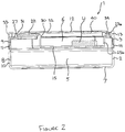
Figure 2 is a cross-sectional side view of the container shown inFigure 1 with the cover in a closed position; -
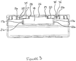
Figure 3 is a cross-sectional front view of the container shown inFigure 1 ; -
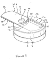
Figure 4 is a perspective view of the container shown inFigure 1 with the cover in an open position; -
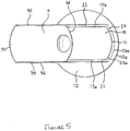
Figure 5 is a plan view of the container shown inFigure 1 with the cover in an open position; -
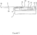
Figure 6 is a cross-sectional side view of the container shown inFigure 1 with the cover in an open position; -
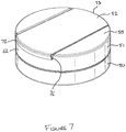
Figure 7 is a perspective view of a container for snus with a lid and a cover according to an alternative embodiment of the invention; -
Figure 8 is a cross-sectional side view of the container shown inFigure 7 with the cover in a closed position; -
Figure 9 is a cross-sectional front view of the container shown inFigure 7 ; -
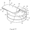
Figure 10 is a perspective view of the container shown inFigure 7 with the cover in an open position; -
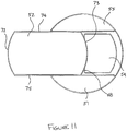
Figure 11 is a plan view of the container shown inFigure 7 with the cover in an open position; and -
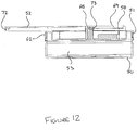
Figure 12 is a cross-sectional view of the container shown inFigure 7 with the cover in an open position. - Referring now to the drawings, a container 1 is shown in
Figures 1 to 6 comprising abase 2, alid 3 and aslidable cover 4. Thebase 2 and thehd 3 define afirst compartment 5 for storing fresh or unused snus, and asecond compartment 6 for holding used snus 'U' is defined in thelid 3. Thecover 4 encloses thesecond compartment 6 when slid into a closed position, as will become apparent hereinafter. - The
base 2 comprises acircular bottom wall 7 having aside wall 8 which upstands from a periphery thereof. An upper portion 9 of theside wall 8 is recessed and has a smaller outer diameter than a lower portion 10 of theside wall 8, and is provided with a circumferential bead 11 extending therearound. - The
lid 3 comprises a circularupper wall 12 from which aperipheral wall 13 depends. Theperipheral wall 13 of thelid 3 has an inner diameter which corresponds to the outer diameter of the upper portion of thebase side wall 8 so that when thefirst compartment 5 is enclosed by thebase 2 andlid 3 being brought together, theperipheral wall 13 extends over and overlaps the top portion 9 of thebase side wall 8. Anannular groove 14 is formed on an inner surface of theperipheral wall 13 of thelid 3 which receives the bead 11 of thebase 2 when the container 1 is closed so as to retain thelid 3 andbase 2 together and so prevent the container 1 from accidentally opening. - The
lid 3 has thesecond compartment 6 which is formed in theupper wall 12 and is closable by thecover 4. Thesecond compartment 6 includes a generally rectangular recess comprising abottom wall 15, with two parallel long side walls 17a, 17b, a firstshort side wall 18 and a second short side wall 19 extending therefrom. The two parallel long side walls 17a, 17b and the firstshort side wall 18 extend from thebottom wall 15 to theupper wall 12. The firstshort side wall 18 extends from thebottom wall 15 to arecessed edge 20 which is recessed below the plane of theupper wall 12, as will be explained below. The first and secondshort side walls 18,19 extend between the two parallel long side walls 17a, 17b. Although the long side walls 17a,17b andshort side walls 18,19 are described as such, it will be understood that the length of the respective side walls are not limited as such, and that in an alternative arrangement the long side walls may be shorter in length and extend a shorter distance along the upper wall than the short side walls. Theshort side walls 18, 19 are arcuate, with the second short side wall 19 lying proximate to a section of theperipheral edge 12a of theupper wall 12 and extending parallel thereto, and thefirst side wall 18 extending parallel to the second short side wall 19. It will be understood that the first andsecond side walls 18,19 may not be arcuate and may have different shapes, such as planar, and may have different shapes to each other. The long side walls 17a,17b and the second short side wall 19 each have astep lower portions Figures 3 to 6 . Thelower portions bottom wall 15 to thestep step upper wall 12 of thelid 3. Although it is not apparent from the drawings, thestep upper portions short side wall 18 to theperipheral wall 13 of thelid 3. Therefore, thesecond compartment 6 extends to theperipheral wall 13 of thelid 3. Formed along theupper portions lip 25 which extends from saidupper portions step lip 25 and thestep Figure 3 . Each track runs along thelong side walls second compartment 6, from the second short side wall 19 to theperipheral wall 13 of thelid 3 beyond thefirst side wall 18. - The
recessed edge 20, which extends along the upper edge of the firstshort side wall 18 is recessed below the plane of theupper wall 12, and a firstupper surface 27 extends therefrom to theperipheral wall 13 of the lid, such that a cut-out is formed in theperipheral wall 13 and defined by theupper portions upper surface 27, such that the second compartment extends to the cut-out formed in the peripheral wall. The firstupper surface 27 lies on the same plane as thestep platform 29 upstands from the firstupper surface 27, with a secondupper surface 28 to define a shoulder against which the cover locates, as will be explained hereinafter, which extends between inner andouter shoulder portions inner shoulder 30 extends from the recessededge 20 of the firstshort side wall 18, and theouter shoulder 31 extends from the firstupper surface 27, proximate to, but stepped in from, theperipheral wall 13 of thelid 3. Theplatform 29 is spaced from theupper portions upper surface 28 is recessed below the plane of theupper wall 12 of thelid 3, as seen inFigures 2 and3 and includes anarcuate channel 26 which extends between the inner andouter shoulders indentation 40 formed in thecover 4 to slide over theplatform 29 without contacting theplatform 29, as will be explained below. - The
cover 4 is of a generally rectangular shape having atop wall 32 with opposing first and secondcover end walls cover side walls 35 depending from the periphery of thetop wall 32. The two opposingcover side walls 35 extend parallel to each other and thecover end walls cover side walls 35. The depth of each of thecover side walls 35 and coverend walls upper portions second compartment 6, such that thetop wall 32 of thecover 4 lies level with theupper wall 12 of thelid 3 when thecover 4 is mounted thereto. - A
rib 36 is formed along an outer surface of eachcover side wall 35, extending between thecover end walls cover side wall 35. The width of thecover 4 between theribs 36 on opposingcovei side walls 35 conforms to the width of thesecond compartment 6, between theupper portions cover 4 is mounted to thelid 3, eachrib 36 locates in the tracks of thelid 3 such that thecover 4 is retained by the lid, and each rib is slidable in its corresponding track so the cover can be slid in a direction parallel to the tracks between a closed and an open position. - The
cover end walls upper wall 13 of thelid 3. The length of thecover 4, between thecover end walls second compartment 6 and the periphery of theperipheral wall 13 at the cut-out, such that the firstcover end wall 33 continues the arc of theperipheral wall 13 when thecover 4 is mounted to thelid 3 and is in the closed position to form a flush outer finish of thelid 3, as shown inFigure 1 . In the closed position, the secondcover end wall 34 abuts the upper portion 23a of the secondshort side wall 23. - To open the
second compartment 6, a user urges the cover to slide along the direction of the long side walls 17a,17b of thesecond compartment 6. By doing so, theribs 36 slide in their corresponding track defined between thesteps lips 25, and the end of thecover 4 proximate the firstcover end wall 33 is slidable from the cut out formed in the lidperipheral wall 13 such that the secondcover end wall 34 moves away from the secondshort side wall 23 of thesecond compartment 6, and an opening to thesecond compartment 6 is formed to allow access to saidsecond compartment 6. As the user further slides thecover 4 into the open position, the secondcover end wall 34 contacts theinner shoulder 30 of theplatform 29, because the platform upstands in a recess defined by the walls of the cover. As can be appreciated fromFigure 6 , thecover 4 is prevented from sliding off the lid due to the presence of theinner shoulder 30. To close thesecond compartment 6 of the container 1, the user slides thecover 4 in the opposite direction until the secondcover end wall 34 abuts the secondshort side wall 23 of thesecond compartment 6, and so the second compartment is enclosed, and the cover is in its closed position. - An alternative embodiment of the present invention will now be described with reference to
Figures 7 to 12 . In this alternative embodiment, the container comprises abase 50, alid 51 and aslidable cover 52. Thebase 50 and thelid 51 define afirst compartment 53 for storing fresh or unused snus, and asecond compartment 54 for holding used snus 'U' is defined in thelid 51. Thecover 52 encloses thesecond compartment 54 when slid into a closed position, as will become apparent hereinafter. Thebase 50 and its configuration with thelid 51 is generally the same as the embodiment described above with reference toFigures 1 to 6 , and so a detailed description will therefore be omitted herein. - In this alternative embodiment, the
cover 52 and thelid 51 are configured such that thecover 52 is slidable in two opposing directions from its closed position, wherein thesecond compartment 54 is enclosed, to open positions, wherein access is provided to thesecond compartment 54. Thelid 51 comprises a circularupper wall 55 with thesecond compartment 54 formed therein. In this embodiment thesecond compartment 54 has abottom wall 56 with opposingparallel side walls bottom wall 56 and opposing secondcompartment end walls parallel side walls bottom wall 56. - The
parallel side walls step 61 dividing each wall into anupper portion 57a,58a, which extends from thebottom wall 56 to thestep 61, and a lower portion 57b,58b, which extends from thestep 61 to theupper wall 55 of thelid 51. Each secondcompartment end wall upper surface 63 extends from an upper edge of each secondcompartment end wall upper surface 63 lies on a plane with thestep 61 of eachparallel side wall upper surface 63 extends to the outer surface of a lidperipheral wall 62 and anupper portion 57a,58a of eachside wall peripheral wall 62, on opposing sides of thelid 51, such that opposing cut-outs 64 are formed in theperipheral wall 62 from which thecover 52 slides. - A
central wall 66 upstands from thebottom wall 55 of thesecond compartment 54 and extends between the two parallel side walls, midway along, to divide thesecond compartment 54 into twosub-compartments 54a,54b. A top surface 67 of thecentral wall 66 lies on a plane with thestep 61 of eachparallel side wall central wall 66 is shown dividing thesecond compartment 54 into two equal sized sub-compartments 54a,54b, it will be understood that thesecond compartment 54 may be divided to form uneven sized sub-compartments. - A
platform 68 upstands from the top surface 67 of thecentral wall 64 to form a shoulder against which thecover 52 abuts when thecover 52 is slid into one of its two open positions, as will become apparent hereinafter. The shoulder extends above the plane of thestep 61, and theupper surface 63 of each arcuate secondcompartment end wall upper wall 55 of thelid 51, as can be appreciated fromFigures 8 and9 . - A
lip 69 is formed along each of the two opposingparallel side walls peripheral wall 62 at each end, such that a track is formed between saidlip 69 and thestep 61 on either side of thesecond compartment 54, as seen inFigures 9 and10 . - The
cover 52 closing thesecond compartment 54 is of a generally rectangular shape and comprises atop wall 70 with opposing first and secondcover end walls cover side walls top wall 70 to form a cover peripheral wall. The two opposingcover side walls cover end walls cover side walls cover side walls end walls upper portion 57a,58a of eachparallel side wall second compartment 54, such that thetop wall 70 of thecover 52 lies level with theupper wall 55 of thelid 51 when thecover 52 is mounted thereto. - A
rib 76 is formed along an outer surface of eachcover side wall cover end walls cover side wall cover 52 between theribs 76 on opposingcover side walls second compartment 54, between theupper portions 57a,58a of each secondcompartment side wall cover 52 is mounted to thelid 51, eachrib 76 locates in a corresponding track of thelid 51 such that thecover 52 is retained by thelid 51, and eachrib 76 is slidable in its corresponding track so thecover 52 can slide in a direction parallel to the tracks between its closed and open positions. - The
cover end walls peripheral wall 62. The length of thecover 52, between thecover end walls peripheral wall 62 of thelid 51 defined by the opposing cut-outs 64, such that thecover end walls peripheral wall 62 when thecover 4 is in its closed position to form a flush outer finish of thelid 61, as shown inFigure 1 . - To access the sub compartments 53a,53b of the
second compartment 53, a user urges thecover 52 to slide along the axis of the lidparallel side walls cover 52. By doing so, eachrib 76 slides in its corresponding track defined between thestep 61 and eachlip 69, and one end of thecover 52 is slidable from one of thecut outs 64 formed in the lidperipheral wall 62 such that the other end of thecover 52 slides away from theperipheral wall 62, towards the centre of thelid 51, and an opening to thesecond compartment 53 is formed to allow access to saidsecond compartment 53. - As the user further slides the
cover 52 into one of the open positions, one of thecover end walls platform 68, because the shoulder upstands above the plane of thestep 61 and extends above the free edge of therespective end wall Figure 12 , thecover 52 is prevented from sliding off thelid 51 due to the presence of said shoulder. To close thesecond compartment 53, the user slides thecover 52 in the opposite direction. If the user continues to slide the cover in said opposite direction relative to thelid 51, the other end of thecover 52 slides from the opposing cut out 64 formed in the lidperipheral wall 62, such that the other sub-compartment is exposed. The other cover endwall platform 68 to restrict movement of thecover 52 relative to thelid 51 and so this configuration also prevents the cover from accidentally detaching from the lid. - It shall be appreciated that the central wall, together with the platform forming the shoulder, may not extend between the two opposing
parallel side walls second compartment 53 into two sub compartments 53a,53b. It is envisaged that any other configuration which forms a shoulder falls within the scope of the present invention. For example, the central wall may be replaced by a protrusion or rod which extends from the bottom wall of thesecond compartment 53, but does not divide the second compartment into two sub-compartments. - The above described configuration of the slidable cover and the second compartment is not restricted to the lid. A second compartment according to any of the above described embodiments may alternatively be formed in the base, or in both the base and the lid. For example, a shoulder and a second compartment may be formed in a main wall of a base, the base being further configured to receive a slidable cover in accordance with any of the described embodiments. It shall also be appreciated that the above embodiments are not restricted to one or two second compartments. For example, a slidable cover according to the present invention may close a plurality of second compartments. Furthermore, a plurality of second compartments formed on the main wall of the lid and/or the base may be closable by individual slidable covers.
- It shall also be understood that the
cover Figures 1 to 6 , thetop wall 32 of thecover 4 is formed with anindentation 40 into which the user can place their thumb or finger as they slide thecover 4 between open and closed positions. As described above, anarcuate channel 26 is formed extending between the inner andouter shoulders platform 29 to allow the indentation to slide therein without contacting said shoulders. A similar indentation may be formed on thecover 52 described with reference toFigures 7 to 12 . However, it should be realised that the indention is not essential to the invention but may improve the ease of opening and closing the disposal compartments 6, 53. - The configuration of the
cover lid disposal compartment cover cover lid - The sliding mechanism of the present invention also provides an improvement over containers having a disposal compartment closable by a cover relying on a clipping function which after repeated use suffers from wear and tear and so is prone to accidental opening as discussed in the introduction.
- It will be appreciated that the invention is not limited to cylindrical containers, and that the base, lid and cover may be formed in many different shapes, for example a cuboid shape, and/or with square edges.
- Although embodiments of the invention have been shown and described, it will be appreciated by those persons skilled in the art that the foregoing description should be regarded as a description of preferred embodiments only and that other embodiments that fall within the scope of the appended claims are considered to form part of this disclosure.
Claims (10)
- A snus container comprising a base (2, 50) and a lid (3, 51) which overlap to define a first compartment (5, 53) for storing fresh snus, a second compartment (6, 54) formed in the lid or the base for storing used snus and a cover (4, 52) characterised in that the cover is slidable between an open and a closed position to allow access to the second compartment when the cover is in its open position, and, wherein the cover (4, 52) has a protruding portion (34, 72, 73) at one end of the cover which is locatable against an upstanding shoulder (30, 68) which upstands in the second compartment such that, when the cover is urged into its open position, the protruding portion abuts said upstanding shoulder to limit the movement of the cover in its open position.
- A snus container according to claim 1, wherein the lid (3, 51) or the base (2, 50) has a wall (12, 55) and the cover (4, 52) lies on a plane of the wall and is slidable on said plane between its open and closed positions.
- A snus container according to claim 2, wherein the wall is an upper wall (12, 55) with a peripheral wall (13, 62) depending therefrom, and the second compartment (6, 54) extends from said upper wall.
- A snus container according to any of claims 1 to 3, wherein the cover (4, 52) comprises a top wall (32, 70) which is extendable over the second compartment (6, 54), and the protruding portion is an end wall (34, 72, 73) extending from the top wall.
- A snus container according to claim 4, wherein the second compartment (6, 54) extends to the peripheral wall (13, 62) to form a cut-out therein, and the end wall (34, 72, 73) covers the cut-out when the cover (4, 52) is in a closed position.
- A snus container according to any of claims 1 to 5, wherein the protruding portion (34, 72) is a first protruding portion and the cover (52) further comprises a second protruding portion (33, 73) spaced from the first protruding portion which is locatable against the upstanding shoulder (68).
- A snus container according to claim 6, wherein the second protruding portion is an end wall (73) extending from the top wall (70).
- A snus container according to claim 6 or claim 7, wherein the shoulder (68) upstands from the centre of the second compartment (54) such that, when the cover (52) is slid in a first direction the first protruding portion (72) abuts said upstanding shoulder to limit the movement of the cover in a first open position, and when the cover is slid in a second direction the second protruding portion (73) abuts said upstanding shoulder to limit the movement of the cover in a second open position.
- A snus container according to claim 6 or claim 7, wherein the shoulder (30) upstands proximal to one end of the second compartment (6) such that, when the cover (4) is slid in a first direction the first protruding portion (34) abuts said upstanding shoulder to limit the movement of the cover in its open position, and when the cover is slid in a second direction the second protruding portion (33) abuts said upstanding shoulder to limit the movement of the cover in its closed position.
- A container according to any preceding claim, wherein the second compartment (6, 54) comprises a bottom wall (15, 56) with parallel side walls (17a, 17b, 57, 58) upstanding therefrom, each upstanding side wall having a step (21, 22, 61) formed therein, and a lip (25, 69) extending along each side wall, spaced from the step to form a track, wherein a portion of the cover 94, 52) is slidably disposed between each lip and step.
Applications Claiming Priority (2)
| Application Number | Priority Date | Filing Date | Title |
|---|---|---|---|
| GBGB0918990.3A GB0918990D0 (en) | 2009-10-30 | 2009-10-30 | A container |
| PCT/EP2010/064546 WO2011051077A1 (en) | 2009-10-30 | 2010-09-30 | A container |
Publications (2)
| Publication Number | Publication Date |
|---|---|
| EP2493340A1 EP2493340A1 (en) | 2012-09-05 |
| EP2493340B1 true EP2493340B1 (en) | 2018-04-25 |
Family
ID=41434870
Family Applications (1)
| Application Number | Title | Priority Date | Filing Date |
|---|---|---|---|
| EP10768200.7A Not-in-force EP2493340B1 (en) | 2009-10-30 | 2010-09-30 | A container |
Country Status (4)
| Country | Link |
|---|---|
| US (1) | US10306921B2 (en) |
| EP (1) | EP2493340B1 (en) |
| GB (1) | GB0918990D0 (en) |
| WO (1) | WO2011051077A1 (en) |
Families Citing this family (14)
| Publication number | Priority date | Publication date | Assignee | Title |
|---|---|---|---|---|
| GB2513163A (en) | 2013-04-18 | 2014-10-22 | British American Tobacco Co | Container |
| US9936729B2 (en) | 2014-10-16 | 2018-04-10 | R.J. Reynolds Tobacco Company | Package for a tobacco-containing material and related packaging method |
| CN106509991B (en) * | 2016-10-18 | 2018-11-13 | 云南中烟工业有限责任公司 | A kind of slidingtype hood-opening device |
| US10463075B2 (en) | 2018-02-08 | 2019-11-05 | Swedish Match North Europe Ab | Snuff container |
| SE545107C2 (en) * | 2018-02-08 | 2023-04-04 | Swedish Match North Europe Ab | A snuff container and manufacturing method thereof |
| USD933418S1 (en) | 2020-06-18 | 2021-10-19 | Helen Of Troy Limited | Closeable tumbler lid |
| US12070059B2 (en) | 2020-09-04 | 2024-08-27 | Nicoventures Trading Limited | Child-resistant container for tobacco-containing products |
| US11760544B2 (en) | 2020-10-14 | 2023-09-19 | Helen Of Troy Limited | Closeable tumbler lid |
| WO2023232332A2 (en) | 2022-04-14 | 2023-12-07 | Nicoventures Trading Limited | Container for oral products |
| USD1066901S1 (en) | 2022-05-18 | 2025-03-18 | Intercontinental Great Brands Llc | Comestible container |
| SE546861C2 (en) * | 2022-09-29 | 2025-02-25 | Inside Innovation Scandinavia Ab | Miniature container and container assembly |
| USD1041154S1 (en) * | 2022-11-04 | 2024-09-10 | Haikou Lili Investment Co., Ltd. | Pill box |
| EP4581946A1 (en) * | 2024-01-08 | 2025-07-09 | Raffael Sodano | Snus socket and joint assembly and kit for forming a snus socket |
| WO2025233800A1 (en) * | 2024-05-06 | 2025-11-13 | G.D S.P.A. | A box, in particular a box of snus |
Family Cites Families (36)
| Publication number | Priority date | Publication date | Assignee | Title |
|---|---|---|---|---|
| US1341295A (en) * | 1920-01-19 | 1920-05-25 | Albert C Burtis | Match-holding attachment for commercial tobacco-boxes |
| US1610647A (en) * | 1924-09-15 | 1926-12-14 | Anderson Fredrick Glascoe | Combination cigarette case, match box, and ash tray |
| US1935840A (en) * | 1931-11-05 | 1933-11-21 | American Tobacco Co | Tobacco receptacle |
| US2008001A (en) * | 1934-12-28 | 1935-07-16 | Merck & Co Inc | Receptacle closure |
| US2058608A (en) | 1935-11-13 | 1936-10-27 | Maeda Rinsai | Cover for containers |
| US2162222A (en) * | 1938-07-20 | 1939-06-13 | Saul L Lachter | Spectacle case |
| US2219179A (en) * | 1938-11-04 | 1940-10-22 | Fayer Elsie | Closure and reinforcer for cigarette and like packages |
| US2237388A (en) * | 1940-02-27 | 1941-04-08 | Terrell E Hutchens | Safety milk bottle cabinet |
| US2378003A (en) * | 1944-07-03 | 1945-06-12 | Charles H Duell | Dispensing container |
| US2531737A (en) * | 1947-07-11 | 1950-11-28 | William E Wilson | Container having spring biased sliding closure |
| US2868360A (en) * | 1954-04-28 | 1959-01-13 | Godfrey Holmes Plastics Ltd | Storage containers for detonators |
| US3362564A (en) * | 1964-10-16 | 1968-01-09 | Oscar G. Mueller | Sliding lid boxes |
| US3352446A (en) * | 1965-06-09 | 1967-11-14 | Wilmot Castle Co | Closure apparatus for pressure chamber |
| US3960270A (en) * | 1975-04-23 | 1976-06-01 | Bob May | Cigarette case |
| US4612943A (en) | 1983-08-05 | 1986-09-23 | Meinkowsky Larry J | Dispenser for snuff and the like |
| EP0350739A1 (en) * | 1988-07-14 | 1990-01-17 | Josef Sattler | Recipient for smoker's articles |
| FR2637573A1 (en) | 1988-10-10 | 1990-04-13 | Stamati Michel | Case with sliding cover |
| US5044500A (en) * | 1989-09-01 | 1991-09-03 | Erie Scientific Company | Package for handling and transporting glass slides |
| US5107990A (en) | 1990-03-14 | 1992-04-28 | Devon Industries, Inc. | Rigid closure lid to a disposable container for holding and disposing of used medical sharps and other medical-surgical materials |
| GB9008484D0 (en) | 1990-04-17 | 1990-06-13 | Leary William P O | Container lid |
| DE9414118U1 (en) * | 1994-08-31 | 1994-11-10 | Rösler, Peter, 88239 Wangen | Packaging container |
| US5709232A (en) * | 1995-11-15 | 1998-01-20 | Charles Chang | Cosmetic jar and storage device |
| ES1038288Y (en) | 1997-09-24 | 1998-12-01 | Cuetara S A | PRACTICABLE LID FOR CONTAINERS. |
| EP0913336A1 (en) | 1997-10-31 | 1999-05-06 | The Procter & Gamble Company | Closing device with automatic opening |
| US5957319A (en) | 1998-07-30 | 1999-09-28 | Shane Da Costa; Cardinall Mowbrey | Garbage container cover and liner protector |
| US6540098B1 (en) | 2001-04-25 | 2003-04-01 | Cambro Manufacturing Company | Food pan cover with sliding lid |
| US6507957B1 (en) * | 2002-01-18 | 2003-01-21 | Michael P. Ingram | Portable container device |
| US20040056035A1 (en) * | 2002-09-25 | 2004-03-25 | Mars, Incorporated | Dispenser with stowable cover |
| SE527350C8 (en) | 2003-08-18 | 2006-03-21 | Gallaher Snus Ab | Lid for snuff box |
| US20050173272A1 (en) * | 2004-02-05 | 2005-08-11 | Lemmons Robert W.Iv | Compartmented smokeless tobacco can |
| US7481339B1 (en) | 2004-08-25 | 2009-01-27 | Medtech Products, Inc. | Hygienic dispensing package |
| GB2419338A (en) | 2004-10-20 | 2006-04-26 | Ann Grimes | Vessel with dispensing outlets at the top and in the base |
| US7584843B2 (en) * | 2005-07-18 | 2009-09-08 | Philip Morris Usa Inc. | Pocket-size hand-held container for consumer items |
| US7611029B2 (en) | 2006-05-18 | 2009-11-03 | Double Team Inc. | Drinking cup lid with a reclosable drink opening using a sliding member |
| US20080073343A1 (en) | 2006-08-16 | 2008-03-27 | Shadrach William S | Container closure system |
| GB0911180D0 (en) * | 2009-06-29 | 2009-08-12 | Fiedler & Lundgren Ab | A container for snus |
-
2009
- 2009-10-30 GB GBGB0918990.3A patent/GB0918990D0/en not_active Ceased
-
2010
- 2010-09-30 WO PCT/EP2010/064546 patent/WO2011051077A1/en not_active Ceased
- 2010-09-30 EP EP10768200.7A patent/EP2493340B1/en not_active Not-in-force
- 2010-09-30 US US13/502,343 patent/US10306921B2/en active Active
Non-Patent Citations (1)
| Title |
|---|
| None * |
Also Published As
| Publication number | Publication date |
|---|---|
| US10306921B2 (en) | 2019-06-04 |
| US20120325698A1 (en) | 2012-12-27 |
| WO2011051077A1 (en) | 2011-05-05 |
| EP2493340A1 (en) | 2012-09-05 |
| GB0918990D0 (en) | 2009-12-16 |
Similar Documents
| Publication | Publication Date | Title |
|---|---|---|
| US10306921B2 (en) | Container | |
| EP2308769B1 (en) | A container for snus | |
| EP2361198B1 (en) | Container for snus | |
| US7793785B2 (en) | Medication dispenser | |
| US8091709B2 (en) | Child-resistant package | |
| US20060283721A1 (en) | Container for consumer article | |
| DK2904914T3 (en) | Container for snuff, tobacco or smoking related products and methods | |
| EP2236433B1 (en) | Container | |
| US20170144807A1 (en) | Two Directional Slide and Lock Package | |
| EP1466844A1 (en) | Package with sliding lid | |
| US12070055B2 (en) | Valet for hand-rolled cigarettes | |
| EP2966001B1 (en) | Container cover with pour spout and spoon | |
| CN111065586B (en) | Receptacles for aerosol-generating articles | |
| JP3163370U (en) | Powder cosmetic container | |
| KR200479403Y1 (en) | Cosmetic Container | |
| JP7560108B2 (en) | Packaging containers | |
| KR101274453B1 (en) | A cigarette case with a function of keeping a cigarbutt | |
| JP2004175362A (en) | Gum container | |
| KR20110000929A (en) | Cigarette Packer with Lighter | |
| RU101433U1 (en) | CAPACITY | |
| EP2870886B1 (en) | Receptacle for tobacco and tobacco related articles and/or smoking articles | |
| GB2526132A (en) | Suspension file storage container | |
| JP2013199298A (en) | Lid |
Legal Events
| Date | Code | Title | Description |
|---|---|---|---|
| PUAI | Public reference made under article 153(3) epc to a published international application that has entered the european phase |
Free format text: ORIGINAL CODE: 0009012 |
|
| 17P | Request for examination filed |
Effective date: 20120323 |
|
| AK | Designated contracting states |
Kind code of ref document: A1 Designated state(s): AL AT BE BG CH CY CZ DE DK EE ES FI FR GB GR HR HU IE IS IT LI LT LU LV MC MK MT NL NO PL PT RO SE SI SK SM TR |
|
| DAX | Request for extension of the european patent (deleted) | ||
| STAA | Information on the status of an ep patent application or granted ep patent |
Free format text: STATUS: EXAMINATION IS IN PROGRESS |
|
| 17Q | First examination report despatched |
Effective date: 20170327 |
|
| GRAP | Despatch of communication of intention to grant a patent |
Free format text: ORIGINAL CODE: EPIDOSNIGR1 |
|
| STAA | Information on the status of an ep patent application or granted ep patent |
Free format text: STATUS: GRANT OF PATENT IS INTENDED |
|
| INTG | Intention to grant announced |
Effective date: 20171107 |
|
| GRAA | (expected) grant |
Free format text: ORIGINAL CODE: 0009210 |
|
| GRAS | Grant fee paid |
Free format text: ORIGINAL CODE: EPIDOSNIGR3 |
|
| STAA | Information on the status of an ep patent application or granted ep patent |
Free format text: STATUS: THE PATENT HAS BEEN GRANTED |
|
| AK | Designated contracting states |
Kind code of ref document: B1 Designated state(s): AL AT BE BG CH CY CZ DE DK EE ES FI FR GB GR HR HU IE IS IT LI LT LU LV MC MK MT NL NO PL PT RO SE SI SK SM TR |
|
| REG | Reference to a national code |
Ref country code: GB Ref legal event code: FG4D |
|
| REG | Reference to a national code |
Ref country code: CH Ref legal event code: EP |
|
| REG | Reference to a national code |
Ref country code: AT Ref legal event code: REF Ref document number: 991872 Country of ref document: AT Kind code of ref document: T Effective date: 20180515 |
|
| REG | Reference to a national code |
Ref country code: IE Ref legal event code: FG4D |
|
| REG | Reference to a national code |
Ref country code: DE Ref legal event code: R096 Ref document number: 602010050211 Country of ref document: DE |
|
| REG | Reference to a national code |
Ref country code: NL Ref legal event code: MP Effective date: 20180425 |
|
| REG | Reference to a national code |
Ref country code: LT Ref legal event code: MG4D |
|
| PG25 | Lapsed in a contracting state [announced via postgrant information from national office to epo] |
Ref country code: NL Free format text: LAPSE BECAUSE OF FAILURE TO SUBMIT A TRANSLATION OF THE DESCRIPTION OR TO PAY THE FEE WITHIN THE PRESCRIBED TIME-LIMIT Effective date: 20180425 |
|
| PG25 | Lapsed in a contracting state [announced via postgrant information from national office to epo] |
Ref country code: ES Free format text: LAPSE BECAUSE OF FAILURE TO SUBMIT A TRANSLATION OF THE DESCRIPTION OR TO PAY THE FEE WITHIN THE PRESCRIBED TIME-LIMIT Effective date: 20180425 Ref country code: BG Free format text: LAPSE BECAUSE OF FAILURE TO SUBMIT A TRANSLATION OF THE DESCRIPTION OR TO PAY THE FEE WITHIN THE PRESCRIBED TIME-LIMIT Effective date: 20180725 Ref country code: LT Free format text: LAPSE BECAUSE OF FAILURE TO SUBMIT A TRANSLATION OF THE DESCRIPTION OR TO PAY THE FEE WITHIN THE PRESCRIBED TIME-LIMIT Effective date: 20180425 Ref country code: FI Free format text: LAPSE BECAUSE OF FAILURE TO SUBMIT A TRANSLATION OF THE DESCRIPTION OR TO PAY THE FEE WITHIN THE PRESCRIBED TIME-LIMIT Effective date: 20180425 Ref country code: SE Free format text: LAPSE BECAUSE OF FAILURE TO SUBMIT A TRANSLATION OF THE DESCRIPTION OR TO PAY THE FEE WITHIN THE PRESCRIBED TIME-LIMIT Effective date: 20180425 Ref country code: NO Free format text: LAPSE BECAUSE OF FAILURE TO SUBMIT A TRANSLATION OF THE DESCRIPTION OR TO PAY THE FEE WITHIN THE PRESCRIBED TIME-LIMIT Effective date: 20180725 Ref country code: PL Free format text: LAPSE BECAUSE OF FAILURE TO SUBMIT A TRANSLATION OF THE DESCRIPTION OR TO PAY THE FEE WITHIN THE PRESCRIBED TIME-LIMIT Effective date: 20180425 |
|
| PG25 | Lapsed in a contracting state [announced via postgrant information from national office to epo] |
Ref country code: GR Free format text: LAPSE BECAUSE OF FAILURE TO SUBMIT A TRANSLATION OF THE DESCRIPTION OR TO PAY THE FEE WITHIN THE PRESCRIBED TIME-LIMIT Effective date: 20180726 Ref country code: HR Free format text: LAPSE BECAUSE OF FAILURE TO SUBMIT A TRANSLATION OF THE DESCRIPTION OR TO PAY THE FEE WITHIN THE PRESCRIBED TIME-LIMIT Effective date: 20180425 Ref country code: LV Free format text: LAPSE BECAUSE OF FAILURE TO SUBMIT A TRANSLATION OF THE DESCRIPTION OR TO PAY THE FEE WITHIN THE PRESCRIBED TIME-LIMIT Effective date: 20180425 |
|
| REG | Reference to a national code |
Ref country code: AT Ref legal event code: MK05 Ref document number: 991872 Country of ref document: AT Kind code of ref document: T Effective date: 20180425 |
|
| PG25 | Lapsed in a contracting state [announced via postgrant information from national office to epo] |
Ref country code: PT Free format text: LAPSE BECAUSE OF FAILURE TO SUBMIT A TRANSLATION OF THE DESCRIPTION OR TO PAY THE FEE WITHIN THE PRESCRIBED TIME-LIMIT Effective date: 20180827 |
|
| REG | Reference to a national code |
Ref country code: DE Ref legal event code: R097 Ref document number: 602010050211 Country of ref document: DE |
|
| PG25 | Lapsed in a contracting state [announced via postgrant information from national office to epo] |
Ref country code: RO Free format text: LAPSE BECAUSE OF FAILURE TO SUBMIT A TRANSLATION OF THE DESCRIPTION OR TO PAY THE FEE WITHIN THE PRESCRIBED TIME-LIMIT Effective date: 20180425 Ref country code: CZ Free format text: LAPSE BECAUSE OF FAILURE TO SUBMIT A TRANSLATION OF THE DESCRIPTION OR TO PAY THE FEE WITHIN THE PRESCRIBED TIME-LIMIT Effective date: 20180425 Ref country code: SK Free format text: LAPSE BECAUSE OF FAILURE TO SUBMIT A TRANSLATION OF THE DESCRIPTION OR TO PAY THE FEE WITHIN THE PRESCRIBED TIME-LIMIT Effective date: 20180425 Ref country code: AT Free format text: LAPSE BECAUSE OF FAILURE TO SUBMIT A TRANSLATION OF THE DESCRIPTION OR TO PAY THE FEE WITHIN THE PRESCRIBED TIME-LIMIT Effective date: 20180425 Ref country code: EE Free format text: LAPSE BECAUSE OF FAILURE TO SUBMIT A TRANSLATION OF THE DESCRIPTION OR TO PAY THE FEE WITHIN THE PRESCRIBED TIME-LIMIT Effective date: 20180425 Ref country code: DK Free format text: LAPSE BECAUSE OF FAILURE TO SUBMIT A TRANSLATION OF THE DESCRIPTION OR TO PAY THE FEE WITHIN THE PRESCRIBED TIME-LIMIT Effective date: 20180425 |
|
| PG25 | Lapsed in a contracting state [announced via postgrant information from national office to epo] |
Ref country code: IT Free format text: LAPSE BECAUSE OF FAILURE TO SUBMIT A TRANSLATION OF THE DESCRIPTION OR TO PAY THE FEE WITHIN THE PRESCRIBED TIME-LIMIT Effective date: 20180425 Ref country code: SM Free format text: LAPSE BECAUSE OF FAILURE TO SUBMIT A TRANSLATION OF THE DESCRIPTION OR TO PAY THE FEE WITHIN THE PRESCRIBED TIME-LIMIT Effective date: 20180425 |
|
| PLBE | No opposition filed within time limit |
Free format text: ORIGINAL CODE: 0009261 |
|
| STAA | Information on the status of an ep patent application or granted ep patent |
Free format text: STATUS: NO OPPOSITION FILED WITHIN TIME LIMIT |
|
| REG | Reference to a national code |
Ref country code: DE Ref legal event code: R119 Ref document number: 602010050211 Country of ref document: DE |
|
| 26N | No opposition filed |
Effective date: 20190128 |
|
| PG25 | Lapsed in a contracting state [announced via postgrant information from national office to epo] |
Ref country code: MC Free format text: LAPSE BECAUSE OF FAILURE TO SUBMIT A TRANSLATION OF THE DESCRIPTION OR TO PAY THE FEE WITHIN THE PRESCRIBED TIME-LIMIT Effective date: 20180425 |
|
| REG | Reference to a national code |
Ref country code: CH Ref legal event code: PL |
|
| GBPC | Gb: european patent ceased through non-payment of renewal fee |
Effective date: 20180930 |
|
| PG25 | Lapsed in a contracting state [announced via postgrant information from national office to epo] |
Ref country code: SI Free format text: LAPSE BECAUSE OF FAILURE TO SUBMIT A TRANSLATION OF THE DESCRIPTION OR TO PAY THE FEE WITHIN THE PRESCRIBED TIME-LIMIT Effective date: 20180425 |
|
| REG | Reference to a national code |
Ref country code: BE Ref legal event code: MM Effective date: 20180930 |
|
| REG | Reference to a national code |
Ref country code: IE Ref legal event code: MM4A |
|
| PG25 | Lapsed in a contracting state [announced via postgrant information from national office to epo] |
Ref country code: LU Free format text: LAPSE BECAUSE OF NON-PAYMENT OF DUE FEES Effective date: 20180930 |
|
| PG25 | Lapsed in a contracting state [announced via postgrant information from national office to epo] |
Ref country code: IE Free format text: LAPSE BECAUSE OF NON-PAYMENT OF DUE FEES Effective date: 20180930 Ref country code: DE Free format text: LAPSE BECAUSE OF NON-PAYMENT OF DUE FEES Effective date: 20190402 |
|
| PG25 | Lapsed in a contracting state [announced via postgrant information from national office to epo] |
Ref country code: BE Free format text: LAPSE BECAUSE OF NON-PAYMENT OF DUE FEES Effective date: 20180930 Ref country code: CH Free format text: LAPSE BECAUSE OF NON-PAYMENT OF DUE FEES Effective date: 20180930 Ref country code: FR Free format text: LAPSE BECAUSE OF NON-PAYMENT OF DUE FEES Effective date: 20180930 Ref country code: LI Free format text: LAPSE BECAUSE OF NON-PAYMENT OF DUE FEES Effective date: 20180930 |
|
| PG25 | Lapsed in a contracting state [announced via postgrant information from national office to epo] |
Ref country code: GB Free format text: LAPSE BECAUSE OF NON-PAYMENT OF DUE FEES Effective date: 20180930 |
|
| PG25 | Lapsed in a contracting state [announced via postgrant information from national office to epo] |
Ref country code: AL Free format text: LAPSE BECAUSE OF FAILURE TO SUBMIT A TRANSLATION OF THE DESCRIPTION OR TO PAY THE FEE WITHIN THE PRESCRIBED TIME-LIMIT Effective date: 20180425 |
|
| PG25 | Lapsed in a contracting state [announced via postgrant information from national office to epo] |
Ref country code: MT Free format text: LAPSE BECAUSE OF NON-PAYMENT OF DUE FEES Effective date: 20180930 |
|
| PG25 | Lapsed in a contracting state [announced via postgrant information from national office to epo] |
Ref country code: TR Free format text: LAPSE BECAUSE OF FAILURE TO SUBMIT A TRANSLATION OF THE DESCRIPTION OR TO PAY THE FEE WITHIN THE PRESCRIBED TIME-LIMIT Effective date: 20180425 |
|
| PG25 | Lapsed in a contracting state [announced via postgrant information from national office to epo] |
Ref country code: HU Free format text: LAPSE BECAUSE OF FAILURE TO SUBMIT A TRANSLATION OF THE DESCRIPTION OR TO PAY THE FEE WITHIN THE PRESCRIBED TIME-LIMIT; INVALID AB INITIO Effective date: 20100930 |
|
| PG25 | Lapsed in a contracting state [announced via postgrant information from national office to epo] |
Ref country code: MK Free format text: LAPSE BECAUSE OF NON-PAYMENT OF DUE FEES Effective date: 20180425 Ref country code: CY Free format text: LAPSE BECAUSE OF FAILURE TO SUBMIT A TRANSLATION OF THE DESCRIPTION OR TO PAY THE FEE WITHIN THE PRESCRIBED TIME-LIMIT Effective date: 20180425 |
|
| PG25 | Lapsed in a contracting state [announced via postgrant information from national office to epo] |
Ref country code: IS Free format text: LAPSE BECAUSE OF FAILURE TO SUBMIT A TRANSLATION OF THE DESCRIPTION OR TO PAY THE FEE WITHIN THE PRESCRIBED TIME-LIMIT Effective date: 20180825 |