EP2493211A2 - Headphone apparatus and sound reproduction method for the same - Google Patents
Headphone apparatus and sound reproduction method for the same Download PDFInfo
- Publication number
- EP2493211A2 EP2493211A2 EP12152486A EP12152486A EP2493211A2 EP 2493211 A2 EP2493211 A2 EP 2493211A2 EP 12152486 A EP12152486 A EP 12152486A EP 12152486 A EP12152486 A EP 12152486A EP 2493211 A2 EP2493211 A2 EP 2493211A2
- Authority
- EP
- European Patent Office
- Prior art keywords
- sound
- headphone
- speaker
- user
- speaker array
- Prior art date
- Legal status (The legal status is an assumption and is not a legal conclusion. Google has not performed a legal analysis and makes no representation as to the accuracy of the status listed.)
- Granted
Links
Images


Classifications
-
- H—ELECTRICITY
- H04—ELECTRIC COMMUNICATION TECHNIQUE
- H04R—LOUDSPEAKERS, MICROPHONES, GRAMOPHONE PICK-UPS OR LIKE ACOUSTIC ELECTROMECHANICAL TRANSDUCERS; DEAF-AID SETS; PUBLIC ADDRESS SYSTEMS
- H04R1/00—Details of transducers, loudspeakers or microphones
- H04R1/10—Earpieces; Attachments therefor ; Earphones; Monophonic headphones
- H04R1/1091—Details not provided for in groups H04R1/1008 - H04R1/1083
-
- H—ELECTRICITY
- H04—ELECTRIC COMMUNICATION TECHNIQUE
- H04R—LOUDSPEAKERS, MICROPHONES, GRAMOPHONE PICK-UPS OR LIKE ACOUSTIC ELECTROMECHANICAL TRANSDUCERS; DEAF-AID SETS; PUBLIC ADDRESS SYSTEMS
- H04R1/00—Details of transducers, loudspeakers or microphones
- H04R1/10—Earpieces; Attachments therefor ; Earphones; Monophonic headphones
-
- H—ELECTRICITY
- H04—ELECTRIC COMMUNICATION TECHNIQUE
- H04R—LOUDSPEAKERS, MICROPHONES, GRAMOPHONE PICK-UPS OR LIKE ACOUSTIC ELECTROMECHANICAL TRANSDUCERS; DEAF-AID SETS; PUBLIC ADDRESS SYSTEMS
- H04R1/00—Details of transducers, loudspeakers or microphones
- H04R1/20—Arrangements for obtaining desired frequency or directional characteristics
- H04R1/32—Arrangements for obtaining desired frequency or directional characteristics for obtaining desired directional characteristic only
- H04R1/40—Arrangements for obtaining desired frequency or directional characteristics for obtaining desired directional characteristic only by combining a number of identical transducers
-
- H—ELECTRICITY
- H04—ELECTRIC COMMUNICATION TECHNIQUE
- H04R—LOUDSPEAKERS, MICROPHONES, GRAMOPHONE PICK-UPS OR LIKE ACOUSTIC ELECTROMECHANICAL TRANSDUCERS; DEAF-AID SETS; PUBLIC ADDRESS SYSTEMS
- H04R3/00—Circuits for transducers, loudspeakers or microphones
- H04R3/12—Circuits for transducers, loudspeakers or microphones for distributing signals to two or more loudspeakers
-
- H—ELECTRICITY
- H04—ELECTRIC COMMUNICATION TECHNIQUE
- H04S—STEREOPHONIC SYSTEMS
- H04S1/00—Two-channel systems
-
- H—ELECTRICITY
- H04—ELECTRIC COMMUNICATION TECHNIQUE
- H04R—LOUDSPEAKERS, MICROPHONES, GRAMOPHONE PICK-UPS OR LIKE ACOUSTIC ELECTROMECHANICAL TRANSDUCERS; DEAF-AID SETS; PUBLIC ADDRESS SYSTEMS
- H04R2430/00—Signal processing covered by H04R, not provided for in its groups
- H04R2430/20—Processing of the output signals of the acoustic transducers of an array for obtaining a desired directivity characteristic
-
- H—ELECTRICITY
- H04—ELECTRIC COMMUNICATION TECHNIQUE
- H04S—STEREOPHONIC SYSTEMS
- H04S2400/00—Details of stereophonic systems covered by H04S but not provided for in its groups
- H04S2400/11—Positioning of individual sound objects, e.g. moving airplane, within a sound field
-
- H—ELECTRICITY
- H04—ELECTRIC COMMUNICATION TECHNIQUE
- H04S—STEREOPHONIC SYSTEMS
- H04S7/00—Indicating arrangements; Control arrangements, e.g. balance control
- H04S7/30—Control circuits for electronic adaptation of the sound field
Definitions
- the present invention relates to a headphone apparatus and a sound reproduction method for the headphone apparatus, and particularly to a headphone apparatus and the like which reproduces two-channel sound signals.
- a headphone user wears a headphone on his/her head so as to cover both ears and listens to a sound signal (acoustic signal) from both ears.
- a sound signal acoustic signal
- the binaural collected sound reproduction scheme is a scheme as follows. That is, microphones called dummy-head microphones are provided for holes of both left and right ears of a dummy head on the assumption of the head of the headphone user. A sound signal from a signal source is collected by the dummy-head microphones.
- the headphone user can feel as if the headphone user were listening to the sound directly from the signal source.
- a binaural collected sound reproduction method it is possible to enhance a sense of direction, a sense of orientation, a sense of presence, and the like.
- a signal source as a special source, which is different from a source for speaker reproduction, which collects sound source signals with a dummy-head microphone, in order to perform such a binaural collected sound reproduction method.
- a reproduction effect that typical two-channel sound signals (stereo signals), for example, are used so as to be oriented outside a head (speaker positions) in the same manner as in speaker reproduction is obtained by applying the aforementioned binaural collected sound reproduction method by the headphone.
- radiation impedance from entrances of external auditory canals of a headphone user to the outside becomes different from that in a case of a headphone non-wearing state.
- Japanese Patent No. 3637596 discloses that headphone sound generating units are positioned so as to be separate from ear auricles of a headphone user.
- a headphone apparatus including: sound reproduction units which respectively reproduce sound signals and are arranged so as to be separated from ear auricles of a headphone user, wherein each of the sound reproduction units is configured by a speaker array including a plurality of speakers.
- the headphone apparatus may be provided with sound reproduction units which respectively reproduce sound signals.
- Each of the sound reproduction units is arranged so as to be separated from an ear auricle of the headphone user and configured by a speaker array including a plurality of speakers.
- a speaker array including a plurality of speakers.
- the sound signal output from each speaker of the speaker array may be configured such that sound formed by the sound signal is focused at a predetermined position. That is, a virtual sound source in which sound pressure is high is created at the predetermined position.
- the focusing may be performed by adding a time difference and/or a level difference to the sound signal output from each speaker of the speaker array.
- the focusing is performed by arranging each speaker of the speaker array on a curved surface so as to surround an ear auricle of the headphone user. In such a case, it is possible to achieve various effects in accordance with the positions of the focusing.
- the focusing may be positioned at an entrance of an external auditory canal of the headphone user.
- the virtual sound source is synthesized at the entrance of the external auditory canal of the headphone user. Since the virtual sound source is an intangible sound source, radiation impedance from the entrance of the external auditory canal of the headphone user to the outside becomes close to that in the non-wearing state, and therefore, it becomes possible to reduce disruptions in a property due to reflection in the speaker array. Accordingly, the acoustic property is less influenced by the ear auricle, and it becomes possible to provide a stable acoustic property in which influences of variations due to individual differences are reduced.
- the focusing may be positioned between the speaker array and the entrance of the external auditory canal of the headphone user.
- the virtual sound source is synthesized between the speaker array and the entrance of the external auditory canal of the headphone user.
- the focusing may be positioned behind the speaker array.
- the virtual sound source is synthesized behind the speaker array. By synthesizing the virtual sound source at such a position, it is possible to enhance a sense of distance in a sound image orientation.
- the sound signal output from each speaker of the speaker array may be configured such that the sound formed by the sound signal becomes a planar wave. In such a case, it is possible to allow states of reflection and refraction in the ear auricle of the headphone user to be close to those in reproduction by placing the speaker away from the headphone user and thereby realizing a natural sound image orientation.
- the headphone apparatus may further include a head motion detecting unit which detects a state of a head of the headphone user, and an orientation of a sound image formed by the sound signal is controlled based on the state of the head of the headphone user, which has been detected by the head motion detecting unit. For example, the position of focusing is changed based on the state of the head of the headphone user. In such a case, it is possible to correct a sound image orientation position so as not to be deviated even when the head of the headphone user moves, and it is possible to allow a sound image position to be coincident with a moving image position, for example.
- Each sound reproduction unit may be arranged in front of or behind the ear auricle of the headphone user, for example.
- a sound generating surface of the speaker array is arranged so as to have a predetermined angle with respect to a surface facing the ear auricle of the headphone user. In so doing, it is possible to reduce the disruptions in a property due to reflection in the speaker array even when each sound reproduction unit is arranged in front of the ear auricle of the headphone user, for example.
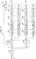
- Fig. 1 shows a configuration example of a stereo headphone system 10 according to a first embodiment.
- the stereo headphone system 10 is provided with an input terminal 101, an A/D converter 102, a signal processing unit 103, D/A converters 104L and 104R, amplifiers 105L and 105R, and a headphone unit 106.
- the input terminal 101 is a terminal to which a sound signal SA is input.
- the A/D converter 102 converts the sound signal SA input to the input terminal 101 from an analog signal to a digital signal.
- the signal processing unit 103 performs filtering to obtain a left channel sound signal SL and a right channel sound signal SR from the sound signal SA. That is, the signal processing unit 103 includes a filter (filter 1) 103L which is for obtaining the left channel sound signal SL from the sound signal SA and a filter (filter 2) 103R which is for obtaining the right channel sound signal SR from the sound signal SA.
- the sound signals SL and SR configure two-channel sound signals.
- Fig. 2 shows a state in which sound is propagated by speaker reproduction.
- the sound reproduced by a speaker SP has a property to which reflection and refraction in ears of a listener M and reflection in a room and the like are added.
- the sound reproduced by the speaker SP reaches both ears of the listener M after a transmission property HL to the left ear and a transmission property HR to the right ear are respectively added thereto.
- the filter 103L is a filter with the transmission property HL from a sound source (speaker SP) located at a position where it is desired to orient a sound image to the left ear of the listener M.
- the filter 103R is a filter with the transmission property HR from the sound source (speaker SP) located at a position where it is desired to orient a sound image to the right ear of the listener M.
- the filters 103L and 103R are configured by FIR (Finite Impulse Response) filters as shown in Fig. 3 , for example.
- the transmission properties HL and HR are measured with impulse response data, for example, and the measurement data is realized with the FIR filters.
- the D/A converters 104L and 104R converts the sound signals SL and SR obtained by the signal processing unit 103 from a digital signal to an analog signal.
- the amplifiers 105L and 105R amplify the analog sound signals SL and SR converted by the D/A converters 104L and 104R and supply the amplified sound signals SL and SR to the sound reproduction units (speaker arrays) 106L and 106R for the left and right channels in the headphone unit 106.
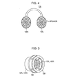
- the sound reproduction units 106L and 106R for the left and right channels in the headphone unit 106 are configured by speaker arrays including a plurality of speakers arranged in array shapes as shown in Fig. 4 .
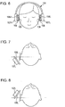
- Each of the sound reproduction units 106L and 106R has a structure as shown in Fig. 5 . That is, each of the sound reproduction units 106L and 106R has a structure arranged so as not to be in contact with an ear auricle of the user (listener) of the headphone unit 106, that is, so as to be separated from the ear auricle.
- contact units 109 are provided so as to protrude via supporting pillars 108 inside the headphone units 107L and 107R with the sound reproduction units (speaker arrays) 106L and 106R disposed in front thereof.
- the contact units 109 are formed to torus shapes and have a configuration in which ear auricles of the headphone user are inserted into hollow parts of the contact units 109.
- Fig. 6 shows a state in which the headphone user (listener) wears the headphone unit 106 on his/her head.
- the aforementioned contact units 109 are pressed onto side parts of a face of the headphone user, and the sound reproduction units (speaker arrays) 106L and 106R are brought to be in a state in which the sound reproduction units (speaker arrays) 106L and 106R are separated from the ear auricles of the headphone user by predetermined distances.
- Figs. 7 and 8 schematically shows arrangement examples of the sound reproduction units (speaker arrays) in a state in which the headphone user wears the headphone unit 106 on his/her head as described above when viewed from an upper direction of the head.
- the sound reproduction unit 106L is shown in Figs. 7 and 8 for simplification of the drawings, the same is true for the sound reproduction unit 106R.
- the sound reproduction unit 106L is arranged behind the ear auricle of the headphone user.
- the sound reproduction unit 106L is arranged in front of the ear auricle of the headphone user. Both arrangement positions are available for the sound reproduction unit.
- a sound generating surface of the sound reproduction unit 106L is not parallel to a surface facing to the ear auricle of the headphone user, for example, a surface shown by a broken line in the drawing, and has a predetermined angle. With such a configuration, it is possible to reduce disruptions in the property due to the reflection in the sound reproduction unit 106L.
- the sound signal output from each speaker of the sound reproduction units (speaker arrays) 106L and 106R is configured such that the sound formed by the sound signal is focused at a predetermined position. In such a case, a virtual sound source in which sound pressure is high is created at the predetermined position.
- the sound signal output from each speaker of the sound reproduction units (speaker arrays) 106L and 106R is configured such that the sound formed by the sound signal becomes a planar wave in this embodiment.
- Fig. 9 shows a configuration example in which the sound formed by the sound signal output from each speaker of the sound reproduction units (speaker arrays) 106L and 106R is focused at a predetermined position.
- each speaker (speaker unit) configuring the sound reproduction unit (speaker array) is arranged on a curve surface so as to be focused at a point which is separated from each speaker by the same distances, namely a focus position.
- each speaker is arranged on a curve surface so as to surround the ear auricle of the headphone user when the headphone user wears the headphone unit 106 as described above.
- Fig. 9A is a diagram of the sound reproduction units (speaker arrays) 106L and 106R when viewed from the front side.
- each of the sound signals SL and SR is supplied to each speaker configuring the sound reproduction units 106L and 106R via the amplifiers 105L and 105R.
- Figs. 10A and 10B show another configuration example in which the sound formed by the sound signal output from each speaker of the sound reproduction units (speaker arrays) 106L and 106R is focused at a predetermined position.
- Figs. 10A and 10B also show a configuration example in which the sound formed by the sound signal output from each speaker of the sound reproduction units (speaker arrays) 106L and 106R is allowed to be a planer wave.
- each speaker (speaker unit) configuring the sound reproduction unit (speaker array) is arranged on a plane as shown in Fig. 10B.
- Fig. 10A is a diagram of the sound reproduction units (speaker arrays) 106L and 106R when viewed from the front side.
- Fig. 10A is a diagram of the sound reproduction units (speaker arrays) 106L and 106R when viewed from the front side. Since it is possible to arrange each speaker on a plane in this case, the structure of the speaker array becomes simple. In addition, it is also possible to freely set a position of a synthesized virtual sound source.
- each of the sound signals SL and SR is supplied to each speaker configuring the sound reproduction units 106L and 106R via series circuits including the delay devices 111L and 111R and the amplifiers 105L and 105R.
- the delay devices 111L and 111R in Fig. 10B are not shown in Fig. 1 , the delay devices 111L and 111R are inserted between the D/A converters 104L and 104R and the amplifiers 105L and 105R, for example.
- the time difference and/or the level difference are added to the sound signal output from each speaker by the delay devices 111L and 111R and the amplifiers 105L and 105R after the sound signals SL and SR are converted into analog signals.
- a configuration can also be considered in which the time difference and/or the level difference are added to the sound signal output from each speaker by the delay devices and the level adjusters in a stage in which the sound signals SL and SR are digital signals.
- Fig. 11 shows a configuration example of the stereo headphone system 10 in such a case.
- delay devices 121L and 121R and level adjusters 122L and 122R are inserted between the filters 103L and 103R and the D/A converters 104L and 104R.
- the order of the delay devices 121L and 121R and the level adjusters 122L and 122R may be opposite.
- the focusing can be positioned both in front of and behind the sound generating surfaces of the sound reproduction units (speaker arrays) 106L and 106R.
- the focusing in front of the sound generating surfaces of the sound reproduction units (speaker arrays) 106L and 106R and synthesize the virtual sound source at the positions, by adding the time difference and the level difference such that the delay time becomes longer while the level becomes lower from a peripheral part to a center.
- the sound signal SA is input to the input terminal 101.
- the sound signal SA is input to the signal processing unit 103 after the sound signal SA is converted from an analog signal to a digital signal by the A/D converter 102.
- the signal processing unit 103 performs filtering on the sound signal SA with the filter (filter 1) 103L to obtain a left channel sound signal SL.
- the signal processing unit 103 performs filtering on the sound signal SA with the filter (filter 2) 103R to obtain a right channel sound signal SR.
- Each of the sound signals SL and SR obtained by the signal processing unit 103 is converted from a digital signal to an analog signal by the D/A converters 104L and 104R, respectively. Then, the sound signals SL and SR are supplied to the sound reproduction units (speaker arrays) 106L and 106R for both channels in the headphone unit 106 after being amplified by the amplifiers 105L and 105R. Then, each speaker of the speaker arrays configuring the sound reproduction units 106L and 106R is driven by the sound signals SL and SR.
- the sound formed by the sound signal output from each speaker of the sound reproduction units (speaker arrays) 106L and 106R is focused at a predetermined position, and the virtual sound source is synthesized at the predetermined position, for example.
- the sound formed by the sound signal output from each speaker of the sound reproduction units (speaker arrays) 106L and 106R is allowed to be a planer wave in this case, for example.
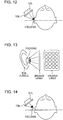
- the focusing of the sound formed by the sound signal output from each speaker of the sound reproduction units (speaker arrays) 106L and 106R can be positioned at the entrance of the external auditory canal of the headphone user (listener) as shown in Fig. 12 .
- the entrance of the external auditory canal described herein includes the vicinity of the entrance of the external auditory canal.
- Fig. 13 shows an example in which the focusing of the sound at the entrance of the external auditory canal is realized by the speaker array in which each speaker is arranged on a plane.
- the virtual sound source is synthesized at the entrance of the external auditory canal.
- the sound source is not a substantial sound source. Therefore, radiation impedance from the entrance of the external auditory canal to the outside becomes close to that in the non-wearing state, and it is possible to reduce disruptions in the property due to reflection in the speaker array as the sound generating unit. Therefore, an acoustic property is less influenced by the ear auricle in this case, and it is possible to reduce the influence by variations due to individual differences and thereby to provide a stable acoustic property to the headphone user.
- the focusing of the sound formed by the sound signal output from each speaker of the sound reproduction units (speaker arrays) 106L and 106R can be positioned between the speaker array and the entrance of the external auditory canal as shown in Fig. 14 , and the virtual sound source is synthesized at the position.
- the speaker array as the sound generating unit is not provided in the vicinity of the ear auricle, and there is no reflection in the speaker array, it is possible to obtain a stable property.
- reflection occurs in the ear auricle of the headphone user (listener) in this case, the reflection is the same as that of the sound which the headphone user usually listens to. That is, since the sound transmitted from the entrance of the external auditory canal to the drum membrane includes a property of the ear auricle of the headphone user (listener), it is possible to improve the front orientation of the sound image.
- the focusing of the sound formed by the sound signal output from each speaker of the sound reproduction units (speaker arrays) 106L and 106R can be positioned behind the speaker array as shown in Fig. 15 , and the virtual sound source with no substance is synthesized at this position. Since the virtual sound source is already synthesized away from the headphone user (listener) in this case, it is possible to enhance a sense of distance in the sound image orientation.
- the sound formed by the sound signal output from each speaker of the sound reproduction units (speaker arrays) 106L and 106R is allowed to be a planer wave as shown in Fig. 16 .
- a sound wave in a low-frequency band namely a sound wave with a long wavelength is generated from the speaker placed in front of the headphone user in a form which is close to that of a planer wave.
- the sound formed by the sound signal output from each speaker of the sound reproduction units (speaker arrays) 106L and 106R can be focused at a predetermined position, and a virtual sound source can be synthesized at the predetermined position.
- a virtual sound source can be synthesized at the predetermined position.
- Fig. 17 shows a configuration example of a stereo headphone system 10A according to a second embodiment.
- the same reference numerals are given to components corresponding to those in Figs. 1 and 11 , and the detailed description thereof will be appropriately omitted.
- the stereo headphone system 10A is provided with the input terminal 101, the A/D converter 102, the signal processing unit 103, the D/A converters 104L and 104R, the amplifiers 105L and 105R, and the headphone unit 106.
- the stereo headphone system 10A is provided with the delay devices 121L and 121R and the level adjusters 122L and 122R between the signal processing unit 103 (filters 103L and 103R) and the D/A converters 104L and 104R.
- the headphone unit 106 is provided with a sensor 131 which detects a state of the head of the headphone user (listener).
- the sensor 131 is an angular velocity sensor such as a gyro sensor, a gravity acceleration sensor, a magnetic sensor, or the like.
- the sensor 131 configures a head motion detecting unit.
- Fig. 18 shows a state in which the headphone user (listener) wears the headphone unit 106 provided with the sensor 131.
- the stereo headphone system 10A shown in Fig. 17 corrects a sound image orientation position by the headphone reproduction so as not to be deviated even when the state of the head is varied as described above.
- the stereo headphone system 10A updates coefficients of the filters 103L and 103R in the signal processing unit 103, namely transmission properties thereof in accordance with the output signal of the sensor 131 and operates such that the sound image orientation position is fixed.
- HL and HR represent transmission properties when the headphone user (listener) faces front as shown in Fig. 19A and HL ⁇ and HR ⁇ represent transmission properties when the headphone user (listener) faces a direction rotated from the front by an angle ⁇ as shown in Fig. 19B .
- the coefficients set in the filters 103L and 103R change from HL to HL ⁇ in the filter 103L and from HR to HR ⁇ in the filter 103R in accordance with the angle ⁇ of the head.
- the stereo headphone system 10A shown in Fig. 17A it is possible to change the properties of the filters 103L and 103R in accordance with the motion of the head of the headphone user (listener) and thereby to avoid deviation of the sound image position with respect to the moving image position when the state of the head is changed. That is, it is possible to allow a direction of the moving image to be coincident with a direction of the sound image and thereby to realize moving image and sound reproduction with high quality.
- the sound image orientation direction By allowing the sound image orientation direction to be equivalent to how the sound sounds when the headphone user does not wear the headphone as described above, it is also possible to achieve an effect that a sense of a front orientation of a sound image is enhanced, which is difficult in the headphone reproduction.
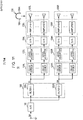
- Fig. 20 shows a configuration example of a stereo headphone system 10B according to a third embodiment.
- the same reference numerals are given to components corresponding to those in Figs. 1 , 11 , and 17 , and the detailed description thereof will be appropriately omitted.
- the stereo headphone system 10B is provided with the input terminal 101, the A/D converter 102, the signal processing unit 103, the D/A converters 104L and 104R, the amplifiers 105L and 105R, and the headphone unit 106.
- the stereo headphone system 10A is provided with the delay devices 121L and 121R and the level adjusters 122L and 122R between the signal processing unit 103 (filters 103L and 103R) and the D/A converters 104L and 104R.
- the headphone unit 106 is provided with the sensor 131 which detects a state of a head of the headphone user (listener) in the same manner as in the aforementioned stereo headphone system 10A.
- the stereo headphone system 10B corrects the sound image orientation position by the headphone reproduction so as not to be deviated even when the state of the head is varied in the same manner as in the aforementioned headphone system 10A.
- the aforementioned stereo headphone system 10A updates coefficients in the filters 103L and 103R of the signal processing unit 103, namely transmission properties thereof in accordance with the motion of the head in accordance with the output signal of the sensor 131.
- the stereo headphone system 10B updates a position of a virtual sound source synthesized by the sound reproduction units (speaker arrays) 106L and 106R in accordance with the output signal of the sensor 131, namely the motion of the head. That is, the stereo headphone system 10B controls delay time and/or a level of the sound signal output to each speaker of the speaker array in accordance with the output signal of the sensor 131, namely the motion of the head, and moves the position of the virtual sound source. In such a case, a delay amount and a level adjustment amount in the delay devices 121L and 121R and the level adjusters 122L and 122R are controlled based on the output signal of the sensor 131.
- the virtual sound source is synthesized at a position Pa.
- the virtual sound source is synthesized at a position Pb which is far from the ear auricles.
- the virtual sound source is synthesized at a position Pc which is close to the ear auricles.
- the virtual sound source is positioned in front of the sound reproduction unit (speaker array 106L). However, the virtual sound source may be at the back position Pb behind the sound reproduction unit (speaker array) 106L as shown in Fig. 22 depending on the angle ⁇ of the head motion of the headphone user (listener).
- the virtual sound source position is controlled in accordance with the motion of the head according to the stereo headphone system 10B shown in Fig. 20 . Therefore, it is possible to fix the sound image orientation position even when the state of the head is varied in the same manner as in the stereo headphone system 10A shown in Fig. 17 and thereby to achieve the same effect.
- control of the virtual sound source corresponds to control of the sound image by wave surface synthesis according to the stereo headphone system 108, it is possible to realize sound image control which is less influenced by the property of the ear auricles of the headphone user (listener).
Abstract
Description
- The present invention relates to a headphone apparatus and a sound reproduction method for the headphone apparatus, and particularly to a headphone apparatus and the like which reproduces two-channel sound signals.
- In the related art, there is a sound reproduction method according to which a headphone user (listener) wears a headphone on his/her head so as to cover both ears and listens to a sound signal (acoustic signal) from both ears. According to the sound reproduction method, a so-called lateralization phenomenon in which a reproduced sound image stays within the head of the listener even if a signal from the signal source is a stereo signal occurs.
- On the other hand, there is a binaural collected sound reproduction method as a sound reproduction method by a headphone. The binaural collected sound reproduction scheme is a scheme as follows. That is, microphones called dummy-head microphones are provided for holes of both left and right ears of a dummy head on the assumption of the head of the headphone user. A sound signal from a signal source is collected by the dummy-head microphones.
- If the headphone user actually wears the headphone and reproduces the thus collected sound signal, the headphone user can feel as if the headphone user were listening to the sound directly from the signal source. According to such a binaural collected sound reproduction method, it is possible to enhance a sense of direction, a sense of orientation, a sense of presence, and the like. However, it is necessary to prepare a signal source as a special source, which is different from a source for speaker reproduction, which collects sound source signals with a dummy-head microphone, in order to perform such a binaural collected sound reproduction method.
- Thus, it can be considered that a reproduction effect that typical two-channel sound signals (stereo signals), for example, are used so as to be oriented outside a head (speaker positions) in the same manner as in speaker reproduction is obtained by applying the aforementioned binaural collected sound reproduction method by the headphone. In order to obtain sound image orientation outside a head with the use of a headphone, radiation impedance from entrances of external auditory canals of a headphone user to the outside becomes different from that in a case of a headphone non-wearing state.
- That is, sound waves from the headphone repeats complicated reflection between ear auricles and headphone sound generating units and are transmitted from the entrances of external auditory canals to drum membranes. For this reason, even if it is attempted to transmit an optimal property to the entrances of external auditory canals or surfaces of the drum membranes, the reflection disturbs the property. Therefore, there is a disadvantage in that it is difficult to stably obtain a satisfactory sound image orientation.
- For example, according to a headphone reproduction method described in Japanese Patent No.
3637596 3637596 - According to the headphone reproduction method disclosed in Japanese Patent No.
3637596 - According to an embodiment of the invention, there is provided a headphone apparatus including: sound reproduction units which respectively reproduce sound signals and are arranged so as to be separated from ear auricles of a headphone user, wherein each of the sound reproduction units is configured by a speaker array including a plurality of speakers.
- The headphone apparatus may be provided with sound reproduction units which respectively reproduce sound signals. Each of the sound reproduction units is arranged so as to be separated from an ear auricle of the headphone user and configured by a speaker array including a plurality of speakers. By configuring each sound reproduction unit by a speaker array as described above, it is possible to satisfactorily reproduce sound signals.
- The sound signal output from each speaker of the speaker array may be configured such that sound formed by the sound signal is focused at a predetermined position. That is, a virtual sound source in which sound pressure is high is created at the predetermined position. For example, the focusing may be performed by adding a time difference and/or a level difference to the sound signal output from each speaker of the speaker array. In addition, the focusing is performed by arranging each speaker of the speaker array on a curved surface so as to surround an ear auricle of the headphone user. In such a case, it is possible to achieve various effects in accordance with the positions of the focusing.
- For example, the focusing may be positioned at an entrance of an external auditory canal of the headphone user. In such a case, the virtual sound source is synthesized at the entrance of the external auditory canal of the headphone user. Since the virtual sound source is an intangible sound source, radiation impedance from the entrance of the external auditory canal of the headphone user to the outside becomes close to that in the non-wearing state, and therefore, it becomes possible to reduce disruptions in a property due to reflection in the speaker array. Accordingly, the acoustic property is less influenced by the ear auricle, and it becomes possible to provide a stable acoustic property in which influences of variations due to individual differences are reduced.
- In addition, the focusing may be positioned between the speaker array and the entrance of the external auditory canal of the headphone user. In such a case, the virtual sound source is synthesized between the speaker array and the entrance of the external auditory canal of the headphone user. By synthesizing the virtual sound source at such a position, there is no tangible sound generating unit in the vicinity of the ear auricle, no reflection occurs in the sound generating unit, and it becomes possible to obtain a stable property. Moreover, it is possible to enhance a front orientation of a sound image with the use of an ear auricle property of the headphone user himself/herself.
- In addition, the focusing may be positioned behind the speaker array. In such a case, the virtual sound source is synthesized behind the speaker array. By synthesizing the virtual sound source at such a position, it is possible to enhance a sense of distance in a sound image orientation.
- The sound signal output from each speaker of the speaker array may be configured such that the sound formed by the sound signal becomes a planar wave. In such a case, it is possible to allow states of reflection and refraction in the ear auricle of the headphone user to be close to those in reproduction by placing the speaker away from the headphone user and thereby realizing a natural sound image orientation.
- The headphone apparatus may further include a head motion detecting unit which detects a state of a head of the headphone user, and an orientation of a sound image formed by the sound signal is controlled based on the state of the head of the headphone user, which has been detected by the head motion detecting unit. For example, the position of focusing is changed based on the state of the head of the headphone user. In such a case, it is possible to correct a sound image orientation position so as not to be deviated even when the head of the headphone user moves, and it is possible to allow a sound image position to be coincident with a moving image position, for example.
- Each sound reproduction unit may be arranged in front of or behind the ear auricle of the headphone user, for example. In such a case, a sound generating surface of the speaker array is arranged so as to have a predetermined angle with respect to a surface facing the ear auricle of the headphone user. In so doing, it is possible to reduce the disruptions in a property due to reflection in the speaker array even when each sound reproduction unit is arranged in front of the ear auricle of the headphone user, for example.
-
-
Fig. 1 is a block diagram showing a configuration example of a stereo headphone system according to a first embodiment; -
Fig. 2 is a diagram showing a state in which sound is propagated by speaker reproduction; -
Fig. 3 is a diagram showing an FIR filter as an example of a digital filter included in a stereo headphone system; -
Fig. 4 is a diagram illustrating that sound reproduction units for left and right channels in a headphone unit are configured by speaker arrays including a plurality of speakers arranged in array shapes; -
Fig. 5 is a diagram illustrating an example of a configuration in which a headphone unit is arranged so as not to be in contact with ear auricles of a headphone user (listener); -
Fig. 6 is a diagram showing a state in which a headphone user wears a headphone unit on his/her head. -
Fig. 7 is a diagram illustrating that sound reproduction units (speaker arrays) in a headphone unit are arranged behind ear auricles of a headphone user; -
Fig. 8 is a diagram illustrating that sound reproduction units (speaker arrays) in a headphone unit are arranged in front of ear auricles of a headphone user; -
Figs. 9A and 9B are diagrams showing a configuration example in which sound formed by sound signals output from each speaker of a sound reproduction unit (speaker array) is focused at a predetermined position; -
Figs. 10A and 10B are diagrams showing another configuration example in which sound formed by sound signals output from each speaker of a sound reproduction unit (speaker array) is focused at a predetermined position; -
Fig. 11 is a block diagram showing a configuration example of a stereo headphone system when a time difference and/or a level difference are added to a sound signal output from each speaker by a delay device and a level adjuster in a stage in which sound signals SL and SR are digital signals; -
Fig. 12 is a diagram illustrating that focusing of sound which is formed by a sound signal output from each speaker of a sound reproducing unit (speaker array) can be positioned at an entrance of an external auditory canal of a headphone user (listener); -
Fig. 13 is a diagram showing an example in which focusing of sound to an entrance of an external auditory canal is realized with a speaker array in which each speaker is arranged on a plane; -
Fig. 14 is a diagram illustrating that focusing of sound which is formed by a sound signal output from each speaker of a sound reproduction unit (speaker array) can be positioned between the speaker array and an entrance of an external auditory canal; -
Fig. 15 is a diagram illustrating that focusing of sound which is formed by a sound signal output from each speaker of a sound reproduction unit (speaker array) can be positioned behind the speaker array; -
Fig. 16 is a diagram illustrating a case in which sound formed by a sound signal output from each speaker of a sound reproduction unit (speaker array) is a planar wave; -
Fig. 17 is a block diagram showing a configuration example of a stereo headphone system according to a second embodiment; -
Fig. 18 is a diagram showing a state in which a headphone user (listener) wears a headphone unit provided with a sensor configuring a head motion detecting unit; -
Figs. 19A and 19B are diagrams showing that transmission properties HL and HR when a headphone user faces front are different from transmission properties HLθ and HRθ when the headphone user faces a direction rotated from the front by an angle θ; -
Fig. 20 is a block diagram showing a configuration example of a stereo headphone system according to a third embodiment; -
Figs. 21A to 21C are diagrams showing an example in which a position of a virtual sound source synthesized by a sound reproduction unit (speaker array) in accordance with a motion of a head is updated; and -
Fig. 22 is a diagram illustrating that a position of a virtual sound source may be behind a sound reproduction unit (speaker array) depending on an angle θ of a head motion of a headphone user (listener). - Hereinafter, description will be given of embodiments of the invention. In addition, the description will be given in the following order.
- 1. First embodiment
- 2. Second embodiment
- 3. Third embodiment
-
Fig. 1 shows a configuration example of astereo headphone system 10 according to a first embodiment. Thestereo headphone system 10 is provided with aninput terminal 101, an A/D converter 102, asignal processing unit 103, D/A converters amplifiers headphone unit 106. - The
input terminal 101 is a terminal to which a sound signal SA is input. The A/D converter 102 converts the sound signal SA input to theinput terminal 101 from an analog signal to a digital signal. Thesignal processing unit 103 performs filtering to obtain a left channel sound signal SL and a right channel sound signal SR from the sound signal SA. That is, thesignal processing unit 103 includes a filter (filter 1) 103L which is for obtaining the left channel sound signal SL from the sound signal SA and a filter (filter 2) 103R which is for obtaining the right channel sound signal SR from the sound signal SA. Here, the sound signals SL and SR configure two-channel sound signals. -
Fig. 2 shows a state in which sound is propagated by speaker reproduction. The sound reproduced by a speaker SP has a property to which reflection and refraction in ears of a listener M and reflection in a room and the like are added. The sound reproduced by the speaker SP reaches both ears of the listener M after a transmission property HL to the left ear and a transmission property HR to the right ear are respectively added thereto. Thefilter 103L is a filter with the transmission property HL from a sound source (speaker SP) located at a position where it is desired to orient a sound image to the left ear of the listener M. In addition, thefilter 103R is a filter with the transmission property HR from the sound source (speaker SP) located at a position where it is desired to orient a sound image to the right ear of the listener M. - It is possible to allow sound equivalent to sound reproduced by the speaker to propagate to both ears of the listener M even when the listener M listens to the sound with the use of the headphone, by obtaining the sound signals SL and SR by the
filters signal processing unit 103. That is, the listener M can listen to oriented sound even with the headphone as if the speaker SP generated the sound. Thefilters Fig. 3 , for example. The transmission properties HL and HR are measured with impulse response data, for example, and the measurement data is realized with the FIR filters. - The D/
A converters signal processing unit 103 from a digital signal to an analog signal. Theamplifiers A converters headphone unit 106. - The
sound reproduction units headphone unit 106 are configured by speaker arrays including a plurality of speakers arranged in array shapes as shown inFig. 4 . Each of thesound reproduction units Fig. 5 . That is, each of thesound reproduction units headphone unit 106, that is, so as to be separated from the ear auricle. - As shown in the drawing,
contact units 109 are provided so as to protrude via supportingpillars 108 inside theheadphone units contact units 109 are formed to torus shapes and have a configuration in which ear auricles of the headphone user are inserted into hollow parts of thecontact units 109. -
Fig. 6 shows a state in which the headphone user (listener) wears theheadphone unit 106 on his/her head. In such a case, theaforementioned contact units 109 are pressed onto side parts of a face of the headphone user, and the sound reproduction units (speaker arrays) 106L and 106R are brought to be in a state in which the sound reproduction units (speaker arrays) 106L and 106R are separated from the ear auricles of the headphone user by predetermined distances. -
Figs. 7 and 8 schematically shows arrangement examples of the sound reproduction units (speaker arrays) in a state in which the headphone user wears theheadphone unit 106 on his/her head as described above when viewed from an upper direction of the head. Although only thesound reproduction unit 106L is shown inFigs. 7 and 8 for simplification of the drawings, the same is true for thesound reproduction unit 106R. - In the example of
Fig. 7 , thesound reproduction unit 106L is arranged behind the ear auricle of the headphone user. In the example ofFig. 8 , thesound reproduction unit 106L is arranged in front of the ear auricle of the headphone user. Both arrangement positions are available for the sound reproduction unit. In such cases, a sound generating surface of thesound reproduction unit 106L is not parallel to a surface facing to the ear auricle of the headphone user, for example, a surface shown by a broken line in the drawing, and has a predetermined angle. With such a configuration, it is possible to reduce disruptions in the property due to the reflection in thesound reproduction unit 106L. - According to this embodiment, the sound signal output from each speaker of the sound reproduction units (speaker arrays) 106L and 106R is configured such that the sound formed by the sound signal is focused at a predetermined position. In such a case, a virtual sound source in which sound pressure is high is created at the predetermined position. Alternatively, the sound signal output from each speaker of the sound reproduction units (speaker arrays) 106L and 106R is configured such that the sound formed by the sound signal becomes a planar wave in this embodiment.
-
Fig. 9 shows a configuration example in which the sound formed by the sound signal output from each speaker of the sound reproduction units (speaker arrays) 106L and 106R is focused at a predetermined position. In this configuration example, as shown inFig. 9B , each speaker (speaker unit) configuring the sound reproduction unit (speaker array) is arranged on a curve surface so as to be focused at a point which is separated from each speaker by the same distances, namely a focus position. In such a case, it is not necessary to individually set delay time and a level for each speaker, and it is possible to realize digital signal processing by one D/A converter for each channel output and one amplifier or reduce the number thereof with respect to the number of the speakers. - In such a case, each speaker is arranged on a curve surface so as to surround the ear auricle of the headphone user when the headphone user wears the
headphone unit 106 as described above.Fig. 9A is a diagram of the sound reproduction units (speaker arrays) 106L and 106R when viewed from the front side. As shown inFig. 9B , each of the sound signals SL and SR is supplied to each speaker configuring thesound reproduction units amplifiers -
Figs. 10A and 10B show another configuration example in which the sound formed by the sound signal output from each speaker of the sound reproduction units (speaker arrays) 106L and 106R is focused at a predetermined position. In addition,Figs. 10A and 10B also show a configuration example in which the sound formed by the sound signal output from each speaker of the sound reproduction units (speaker arrays) 106L and 106R is allowed to be a planer wave. In this configuration example, each speaker (speaker unit) configuring the sound reproduction unit (speaker array) is arranged on a plane as shown inFig. 10B. Fig. 10A is a diagram of the sound reproduction units (speaker arrays) 106L and 106R when viewed from the front side.Fig. 10A is a diagram of the sound reproduction units (speaker arrays) 106L and 106R when viewed from the front side. Since it is possible to arrange each speaker on a plane in this case, the structure of the speaker array becomes simple. In addition, it is also possible to freely set a position of a synthesized virtual sound source. - As shown in
Fig. 10B , each of the sound signals SL and SR is supplied to each speaker configuring thesound reproduction units delay devices amplifiers delay devices Fig. 10B are not shown inFig. 1 , thedelay devices A converters amplifiers Figs. 10A and 10B , it is possible to allow the sound formed by the sound signal output from each speaker to be focused at a predetermined position by adding a time difference and/or a level difference to the sound signal output from each speaker by the delay devices and the amplifiers. - In
Fig. 10B , the time difference and/or the level difference are added to the sound signal output from each speaker by thedelay devices amplifiers -
Fig. 11 shows a configuration example of thestereo headphone system 10 in such a case. In this case,delay devices level adjusters filters A converters delay devices level adjusters - In such a case, the focusing can be positioned both in front of and behind the sound generating surfaces of the sound reproduction units (speaker arrays) 106L and 106R. For example, it is possible to position the focusing in front of the sound generating surfaces of the sound reproduction units (speaker arrays) 106L and 106R and synthesize the virtual sound source at the positions, by adding the time difference and the level difference such that the delay time becomes longer while the level becomes lower from a peripheral part to a center. On the other hand, it is possible to position the focusing behind the sound generating surfaces of the sound reproduction units (speaker arrays) 106L and 106R and synthesize the virtual sound source at the positions, by adding the time difference and the level difference such that the delay time becomes longer while the level becomes smaller from the center to the peripheral part.
- In the configuration example shown in
Figs. 10A and 10B , it is possible to allow the sound formed by the sound signal output from each speaker to be a planer wave if the time difference and/or the level difference are not added to the sound signal output from each speaker by the delay devices and the amplifiers. In such a case, thedelay devices - Next, description will be given of the operation of the
stereo headphone system 10 shown inFig. 1 . The sound signal SA is input to theinput terminal 101. The sound signal SA is input to thesignal processing unit 103 after the sound signal SA is converted from an analog signal to a digital signal by the A/D converter 102. Thesignal processing unit 103 performs filtering on the sound signal SA with the filter (filter 1) 103L to obtain a left channel sound signal SL. In addition, thesignal processing unit 103 performs filtering on the sound signal SA with the filter (filter 2) 103R to obtain a right channel sound signal SR. - Each of the sound signals SL and SR obtained by the
signal processing unit 103 is converted from a digital signal to an analog signal by the D/A converters headphone unit 106 after being amplified by theamplifiers sound reproduction units - In such a case, the sound formed by the sound signal output from each speaker of the sound reproduction units (speaker arrays) 106L and 106R is focused at a predetermined position, and the virtual sound source is synthesized at the predetermined position, for example. Alternatively, the sound formed by the sound signal output from each speaker of the sound reproduction units (speaker arrays) 106L and 106R is allowed to be a planer wave in this case, for example.
- First, description will be given of a case in which the sound formed by the sound signal output from each speaker of the sound reproduction units (speaker arrays) 106L and 106R is focused at a predetermined position and the position corresponds to one of the following (1) to (3).
- The focusing of the sound formed by the sound signal output from each speaker of the sound reproduction units (speaker arrays) 106L and 106R can be positioned at the entrance of the external auditory canal of the headphone user (listener) as shown in
Fig. 12 . The entrance of the external auditory canal described herein includes the vicinity of the entrance of the external auditory canal.Fig. 13 shows an example in which the focusing of the sound at the entrance of the external auditory canal is realized by the speaker array in which each speaker is arranged on a plane. - In such a case, the virtual sound source is synthesized at the entrance of the external auditory canal. The sound source is not a substantial sound source. Therefore, radiation impedance from the entrance of the external auditory canal to the outside becomes close to that in the non-wearing state, and it is possible to reduce disruptions in the property due to reflection in the speaker array as the sound generating unit. Therefore, an acoustic property is less influenced by the ear auricle in this case, and it is possible to reduce the influence by variations due to individual differences and thereby to provide a stable acoustic property to the headphone user. In addition, it is possible to reduce attenuation in energy propagation by creating a virtual sound source, in which sound pressure becomes higher, between the ear auricle and a real speaker and thereby to secure sufficient volume even if the real sound generation unit is away from the entrance of the external auditory canal.
- The focusing of the sound formed by the sound signal output from each speaker of the sound reproduction units (speaker arrays) 106L and 106R can be positioned between the speaker array and the entrance of the external auditory canal as shown in
Fig. 14 , and the virtual sound source is synthesized at the position. - Since the sound source is not a substantial sound source in this case, the speaker array as the sound generating unit is not provided in the vicinity of the ear auricle, and there is no reflection in the speaker array, it is possible to obtain a stable property. Although reflection occurs in the ear auricle of the headphone user (listener) in this case, the reflection is the same as that of the sound which the headphone user usually listens to. That is, since the sound transmitted from the entrance of the external auditory canal to the drum membrane includes a property of the ear auricle of the headphone user (listener), it is possible to improve the front orientation of the sound image.
- The focusing of the sound formed by the sound signal output from each speaker of the sound reproduction units (speaker arrays) 106L and 106R can be positioned behind the speaker array as shown in
Fig. 15 , and the virtual sound source with no substance is synthesized at this position. Since the virtual sound source is already synthesized away from the headphone user (listener) in this case, it is possible to enhance a sense of distance in the sound image orientation. - Next, description will be given of a case in which the sound formed by the sound signal output from each speaker of the sound reproduction units (speaker arrays) 106L and 106R is allowed to be a planer wave as shown in
Fig. 16 . A sound wave from a real sound source at a position away from the headphone user (listener), for example, a speaker located in front of the headphone listener to both ears of the listener becomes close to a planar wave in the vicinity of the ear auricle. In addition, a sound wave in a low-frequency band, namely a sound wave with a long wavelength is generated from the speaker placed in front of the headphone user in a form which is close to that of a planer wave. - It is possible to approximate the states of reflection and refraction in the ear auricle of the headphone user to a state in the reproduction by the speaker placed away from the headphone user by allowing the sound formed by the sound signal output from each speaker of the sound reproduction units (speaker arrays) 106L and 106R to be a planar wave as described above. Therefore, a natural sound image orientation can be achieved. In addition, reproducibility of sound in a low-frequency band is enhanced.
- It is possible to satisfactorily reproduce two-channel sound signals in the
stereo headphone system 10 shown inFig. 1 as described above. That is, the sound formed by the sound signal output from each speaker of the sound reproduction units (speaker arrays) 106L and 106R can be focused at a predetermined position, and a virtual sound source can be synthesized at the predetermined position. As described above, it is possible to achieve various effects in accordance with the focus position by positioning the focusing at the entrance of the external auditory canal of the headphone user, between the speaker array and the entrance of the external auditory canal, behind the speaker array, and the like. In addition, it is possible to allow the sound formed by the sound signal output from each speaker of the sound reproduction units (speaker arrays) 106L and 106R to be a planar wave and thereby to achieve effects such as an effect that a natural sound image orientation becomes possible as described above. -
Fig. 17 shows a configuration example of astereo headphone system 10A according to a second embodiment. InFig. 17 , the same reference numerals are given to components corresponding to those inFigs. 1 and11 , and the detailed description thereof will be appropriately omitted. - The
stereo headphone system 10A is provided with theinput terminal 101, the A/D converter 102, thesignal processing unit 103, the D/A converters amplifiers headphone unit 106. In addition, thestereo headphone system 10A is provided with thedelay devices level adjusters filters A converters - In the
stereo headphone system 10A, theheadphone unit 106 is provided with asensor 131 which detects a state of the head of the headphone user (listener). Thesensor 131 is an angular velocity sensor such as a gyro sensor, a gravity acceleration sensor, a magnetic sensor, or the like. Thesensor 131 configures a head motion detecting unit.Fig. 18 shows a state in which the headphone user (listener) wears theheadphone unit 106 provided with thesensor 131. - Since the sound reproduction unit of the headphone is generally fixed to the head of the headphone user (listener), the sound reproduction unit moves in conjunction with the motion of the head. The
stereo headphone system 10A shown inFig. 17 corrects a sound image orientation position by the headphone reproduction so as not to be deviated even when the state of the head is varied as described above. Thestereo headphone system 10A updates coefficients of thefilters signal processing unit 103, namely transmission properties thereof in accordance with the output signal of thesensor 131 and operates such that the sound image orientation position is fixed. - For example, it is assumed that HL and HR represent transmission properties when the headphone user (listener) faces front as shown in
Fig. 19A and HLθ and HRθ represent transmission properties when the headphone user (listener) faces a direction rotated from the front by an angle θ as shown inFig. 19B . The coefficients set in thefilters filter 103L and from HR to HRθ in thefilter 103R in accordance with the angle θ of the head. - As described above, it is possible to fix the sound image orientation position by updating the coefficients of the
filters - According to the
stereo headphone system 10A shown inFig. 17A , however, it is possible to change the properties of thefilters -
Fig. 20 shows a configuration example of astereo headphone system 10B according to a third embodiment. InFig. 20 , the same reference numerals are given to components corresponding to those inFigs. 1 ,11 , and17 , and the detailed description thereof will be appropriately omitted. - The
stereo headphone system 10B is provided with theinput terminal 101, the A/D converter 102, thesignal processing unit 103, the D/A converters amplifiers headphone unit 106. In addition, thestereo headphone system 10A is provided with thedelay devices level adjusters filters A converters - In the
stereo headphone system 10B, theheadphone unit 106 is provided with thesensor 131 which detects a state of a head of the headphone user (listener) in the same manner as in the aforementionedstereo headphone system 10A. Thestereo headphone system 10B corrects the sound image orientation position by the headphone reproduction so as not to be deviated even when the state of the head is varied in the same manner as in theaforementioned headphone system 10A. - The aforementioned
stereo headphone system 10A updates coefficients in thefilters signal processing unit 103, namely transmission properties thereof in accordance with the motion of the head in accordance with the output signal of thesensor 131. However, thestereo headphone system 10B updates a position of a virtual sound source synthesized by the sound reproduction units (speaker arrays) 106L and 106R in accordance with the output signal of thesensor 131, namely the motion of the head. That is, thestereo headphone system 10B controls delay time and/or a level of the sound signal output to each speaker of the speaker array in accordance with the output signal of thesensor 131, namely the motion of the head, and moves the position of the virtual sound source. In such a case, a delay amount and a level adjustment amount in thedelay devices level adjusters sensor 131. - For example, when the headphone user (listener) faces a front direction as shown in
Fig. 21A , the virtual sound source is synthesized at a position Pa. Next, when the headphone user (listener) rotates his/her head to a left direction by an angle θ and faces the left direction as shown inFig. 21B , the virtual sound source is synthesized at a position Pb which is far from the ear auricles. On the other hand, when the headphone user (listener) rotates his/her head to a right direction by the angle θ and faces the right direction as shown inFig. 21C , the virtual sound source is synthesized at a position Pc which is close to the ear auricles. - In
Figs. 21A to 21C , the virtual sound source is positioned in front of the sound reproduction unit (speaker array 106L). However, the virtual sound source may be at the back position Pb behind the sound reproduction unit (speaker array) 106L as shown inFig. 22 depending on the angle θ of the head motion of the headphone user (listener). - As described above, the virtual sound source position is controlled in accordance with the motion of the head according to the
stereo headphone system 10B shown inFig. 20 . Therefore, it is possible to fix the sound image orientation position even when the state of the head is varied in the same manner as in thestereo headphone system 10A shown inFig. 17 and thereby to achieve the same effect. In addition, since control of the virtual sound source corresponds to control of the sound image by wave surface synthesis according to thestereo headphone system 108, it is possible to realize sound image control which is less influenced by the property of the ear auricles of the headphone user (listener). - The present disclosure contains subject matter related to that disclosed in Japanese Priority Patent Application
JP 2011-040964 - It should be understood by those skilled in the art that various modifications, combinations, sub-combinations and alterations may occur depending on design requirements and other factors insofar as they are within the scope of the appended claims or the equivalents thereof.
Claims (15)
- A headphone apparatus comprising:sound reproduction units which respectively reproduce sound signals and are arranged so as to be separated from ear auricles of a headphone user,wherein each of the sound reproduction units is configured by a speaker array including a plurality of speakers.
- The headphone apparatus according to Claim 1,
wherein a sound signal output from each speaker of the speaker array is configured such that sound formed by the sound signal is focused at a predetermined position. - The headphone apparatus according to Claim 2,
wherein the focusing is performed by adding a time difference and/or a level difference to the sound signal output from each speaker of the speaker array. - The headphone apparatus according to Claim 3, further comprising:a head motion detecting unit which detects a state of a head of the headphone user,wherein a position of the focusing is changed based on the state of the head of the headphone user detected by the head motion detecting unit.
- The headphone apparatus according to Claim 2,
wherein the focusing is performed by arranging each speaker of the speaker array on a curve surface so as to surround an ear auricle of the headphone user. - The headphone apparatus according to Claim 2,
wherein the focusing is positioned at an entrance of an external auditory canal of the headphone user. - The headphone apparatus according to Claim 2,
wherein the focusing is positioned between the speaker array and the entrance of the external auditory canal of the headphone user. - The headphone apparatus according to Claim 2,
wherein the focusing is positioned behind the speaker array. - The headphone apparatus according to Claim 1,
wherein the sound signal output from each speaker of the speaker array is configured such that the sound formed by the sound signal becomes a planer wave. - The headphone apparatus according to Claim 1, further comprising:a head motion detecting unit which detects a state of a head of the headphone user,wherein an orientation of a sound image formed by the sound signal is controlled based on the state of the head of the headphone user, which has been detected by the head motion detecting unit.
- The headphone apparatus according to Claim 1,
wherein each of the sound reproduction units is arranged in front of the ear auricle of the headphone user. - The headphone apparatus according to Claim 11,
wherein a sound generating surface of the speaker array is arranged so as to have a predetermined angle with respect to a surface facing the ear auricle of the headphone user. - The headphone apparatus according to Claim 1,
wherein each of the sound reproduction units is arranged behind the ear auricle of the headphone user. - The headphone apparatus according to Claim 13,
wherein a sound generating surface of the speaker array is arranged so as to have a predetermined angle with respect to a surface facing the ear auricle of the headphone user. - A sound reproduction method for a headphone apparatus comprising:configuring each sound reproduction unit of a stereo headphone apparatus with a speaker array including a plurality of speakers and arranging each sound reproduction unit so as to be separated from an ear auricle of a headphone user; andreproducing sound signals via each speaker array.
Applications Claiming Priority (1)
| Application Number | Priority Date | Filing Date | Title |
|---|---|---|---|
| JP2011040964A JP5716451B2 (en) | 2011-02-25 | 2011-02-25 | Headphone device and sound reproduction method for headphone device |
Publications (3)
| Publication Number | Publication Date |
|---|---|
| EP2493211A2 true EP2493211A2 (en) | 2012-08-29 |
| EP2493211A3 EP2493211A3 (en) | 2013-05-22 |
| EP2493211B1 EP2493211B1 (en) | 2016-01-13 |
Family
ID=45655235
Family Applications (1)
| Application Number | Title | Priority Date | Filing Date |
|---|---|---|---|
| EP12152486.2A Not-in-force EP2493211B1 (en) | 2011-02-25 | 2012-01-25 | Headphone apparatus and sound reproduction method for the same |
Country Status (5)
| Country | Link |
|---|---|
| US (1) | US9191733B2 (en) |
| EP (1) | EP2493211B1 (en) |
| JP (1) | JP5716451B2 (en) |
| KR (1) | KR101912466B1 (en) |
| CN (1) | CN102651831A (en) |
Cited By (3)
| Publication number | Priority date | Publication date | Assignee | Title |
|---|---|---|---|---|
| EP3346731A1 (en) * | 2017-01-04 | 2018-07-11 | Harman Becker Automotive Systems GmbH | Systems and methods for generating natural directional pinna cues for virtual sound source synthesis |
| EP3466114B1 (en) * | 2016-06-06 | 2020-05-13 | Bose Corporation | Acoustic device to be worn on the body |
| CN112351379A (en) * | 2020-10-28 | 2021-02-09 | 歌尔光学科技有限公司 | Control method of audio component and intelligent head-mounted device |
Families Citing this family (17)
| Publication number | Priority date | Publication date | Assignee | Title |
|---|---|---|---|---|
| US9319773B2 (en) * | 2013-08-20 | 2016-04-19 | Ideavillage Products Corporation | Audio bass resonator |
| JP6242262B2 (en) * | 2014-03-27 | 2017-12-06 | フォスター電機株式会社 | Sound playback device |
| CN105282642A (en) * | 2014-07-24 | 2016-01-27 | 宏碁股份有限公司 | Headphone and sound channel control method thereof |
| WO2016140058A1 (en) * | 2015-03-04 | 2016-09-09 | シャープ株式会社 | Sound signal reproduction device, sound signal reproduction method, program and recording medium |
| CN106067996B (en) * | 2015-04-24 | 2019-09-17 | 松下知识产权经营株式会社 | Voice reproduction method, voice dialogue device |
| JP6799141B2 (en) * | 2016-08-01 | 2020-12-09 | マジック リープ, インコーポレイテッドMagic Leap,Inc. | Mixed reality system using spatial audio |
| CN106303832B (en) | 2016-09-30 | 2019-12-27 | 歌尔科技有限公司 | Loudspeaker, method for improving directivity, head-mounted equipment and method |
| US10540138B2 (en) * | 2018-01-25 | 2020-01-21 | Harman International Industries, Incorporated | Wearable sound system with configurable privacy modes |
| TWI698132B (en) | 2018-07-16 | 2020-07-01 | 宏碁股份有限公司 | Sound outputting device, processing device and sound controlling method thereof |
| CN110740415B (en) * | 2018-07-20 | 2022-04-26 | 宏碁股份有限公司 | Sound effect output device, arithmetic device and sound effect control method thereof |
| US10645487B2 (en) * | 2018-07-23 | 2020-05-05 | Warped Dynamics, LLC | Vertically configured parametric transducer headphones |
| CN109379659A (en) * | 2018-11-16 | 2019-02-22 | 王美金 | It is a kind of for virtually with the human-computer interaction acoustics of augmented reality orient earphone |
| US10575094B1 (en) * | 2018-12-13 | 2020-02-25 | Dts, Inc. | Combination of immersive and binaural sound |
| CN110099326B (en) * | 2019-05-24 | 2022-05-06 | 潍坊歌尔电子有限公司 | Headset with play function and adjusting method and device thereof |
| US11197083B2 (en) * | 2019-08-07 | 2021-12-07 | Bose Corporation | Active noise reduction in open ear directional acoustic devices |
| US11284194B2 (en) | 2020-07-06 | 2022-03-22 | Harman International Industries, Incorporated | Techniques for generating spatial sound via head-mounted external facing speakers |
| WO2022009722A1 (en) | 2020-07-09 | 2022-01-13 | ソニーグループ株式会社 | Acoustic output device and control method for acoustic output device |
Citations (2)
| Publication number | Priority date | Publication date | Assignee | Title |
|---|---|---|---|---|
| JP3637596B2 (en) | 1994-01-27 | 2005-04-13 | ソニー株式会社 | Audio playback device and headphones |
| JP2011040964A (en) | 2009-08-10 | 2011-02-24 | Nippon Hoso Kyokai <Nhk> | Decoder of digital transmission method, and reception device |
Family Cites Families (19)
| Publication number | Priority date | Publication date | Assignee | Title |
|---|---|---|---|---|
| US5495534A (en) * | 1990-01-19 | 1996-02-27 | Sony Corporation | Audio signal reproducing apparatus |
| JPH05336599A (en) * | 1992-06-03 | 1993-12-17 | Fujitsu Ltd | Sound image localization headphone device and virtual reality audio-visual equipment using it |
| JPH0795698A (en) * | 1993-09-21 | 1995-04-07 | Sony Corp | Audio reproducing device |
| US5717767A (en) * | 1993-11-08 | 1998-02-10 | Sony Corporation | Angle detection apparatus and audio reproduction apparatus using it |
| JP3577798B2 (en) * | 1995-08-31 | 2004-10-13 | ソニー株式会社 | Headphone equipment |
| US5684879A (en) * | 1996-01-19 | 1997-11-04 | Verdick; Michael | Combination head mounted speaker assembly and multi-channel audio processing system |
| AUPO316096A0 (en) * | 1996-10-23 | 1996-11-14 | Lake Dsp Pty Limited | Head tracking with limited angle output |
| JPH11275696A (en) * | 1998-01-22 | 1999-10-08 | Sony Corp | Headphone, headphone adapter, and headphone device |
| AUPP271598A0 (en) * | 1998-03-31 | 1998-04-23 | Lake Dsp Pty Limited | Headtracked processing for headtracked playback of audio signals |
| JP4281937B2 (en) * | 2000-02-02 | 2009-06-17 | パナソニック株式会社 | Headphone system |
| US7684577B2 (en) * | 2001-05-28 | 2010-03-23 | Mitsubishi Denki Kabushiki Kaisha | Vehicle-mounted stereophonic sound field reproducer |
| HRP20020861A2 (en) * | 2002-10-31 | 2005-02-28 | Milneršić Siniša | Multichannel headphones |
| FR2854537A1 (en) * | 2003-04-29 | 2004-11-05 | Hong Cong Tuyen Pham | ACOUSTIC HEADPHONES FOR THE SPATIAL SOUND RETURN. |
| JP4254502B2 (en) * | 2003-11-21 | 2009-04-15 | ヤマハ株式会社 | Array speaker device |
| JP4308790B2 (en) * | 2004-03-22 | 2009-08-05 | 固昌通訊股▲ふん▼有限公司 | Multi-channel earphone |
| GB0419346D0 (en) * | 2004-09-01 | 2004-09-29 | Smyth Stephen M F | Method and apparatus for improved headphone virtualisation |
| JP2006115396A (en) * | 2004-10-18 | 2006-04-27 | Sony Corp | Reproduction method of audio signal and reproducing apparatus therefor |
| US8515103B2 (en) * | 2009-12-29 | 2013-08-20 | Cyber Group USA Inc. | 3D stereo earphone with multiple speakers |
| JP5696427B2 (en) * | 2010-10-22 | 2015-04-08 | ソニー株式会社 | Headphone device |
-
2011
- 2011-02-25 JP JP2011040964A patent/JP5716451B2/en not_active Expired - Fee Related
-
2012
- 2012-01-25 EP EP12152486.2A patent/EP2493211B1/en not_active Not-in-force
- 2012-02-16 US US13/398,160 patent/US9191733B2/en not_active Expired - Fee Related
- 2012-02-17 CN CN2012100368531A patent/CN102651831A/en active Pending
- 2012-02-17 KR KR1020120016457A patent/KR101912466B1/en active IP Right Grant
Patent Citations (2)
| Publication number | Priority date | Publication date | Assignee | Title |
|---|---|---|---|---|
| JP3637596B2 (en) | 1994-01-27 | 2005-04-13 | ソニー株式会社 | Audio playback device and headphones |
| JP2011040964A (en) | 2009-08-10 | 2011-02-24 | Nippon Hoso Kyokai <Nhk> | Decoder of digital transmission method, and reception device |
Cited By (4)
| Publication number | Priority date | Publication date | Assignee | Title |
|---|---|---|---|---|
| EP3466114B1 (en) * | 2016-06-06 | 2020-05-13 | Bose Corporation | Acoustic device to be worn on the body |
| EP3346731A1 (en) * | 2017-01-04 | 2018-07-11 | Harman Becker Automotive Systems GmbH | Systems and methods for generating natural directional pinna cues for virtual sound source synthesis |
| US10565975B2 (en) | 2017-01-04 | 2020-02-18 | Harman Becker Automotive Systems Gmbh | Systems and methods for generating natural directional pinna cues for virtual sound source synthesis |
| CN112351379A (en) * | 2020-10-28 | 2021-02-09 | 歌尔光学科技有限公司 | Control method of audio component and intelligent head-mounted device |
Also Published As
| Publication number | Publication date |
|---|---|
| JP2012178748A (en) | 2012-09-13 |
| KR20120098429A (en) | 2012-09-05 |
| US20120219165A1 (en) | 2012-08-30 |
| EP2493211A3 (en) | 2013-05-22 |
| JP5716451B2 (en) | 2015-05-13 |
| CN102651831A (en) | 2012-08-29 |
| EP2493211B1 (en) | 2016-01-13 |
| US9191733B2 (en) | 2015-11-17 |
| KR101912466B1 (en) | 2018-10-26 |
Similar Documents
| Publication | Publication Date | Title |
|---|---|---|
| EP2493211B1 (en) | Headphone apparatus and sound reproduction method for the same | |
| RU2698778C2 (en) | System and device for generating head related audio transfer function | |
| KR100416757B1 (en) | Multi-channel audio reproduction apparatus and method for loud-speaker reproduction | |
| JP4304636B2 (en) | SOUND SYSTEM, SOUND DEVICE, AND OPTIMAL SOUND FIELD GENERATION METHOD | |
| JP5696427B2 (en) | Headphone device | |
| EP2873251B1 (en) | An audio signal output device and method of processing an audio signal | |
| JP4913256B1 (en) | Earpiece for canal type receiver, canal type receiver using the earpiece, and stethoscope and hearing aid using the canal type receiver | |
| KR101486448B1 (en) | Sound transducer | |
| CN107426660B (en) | Hearing aid comprising a directional microphone system | |
| US8442244B1 (en) | Surround sound system | |
| JPH01192299A (en) | Stereophonic sound collector | |
| KR20060041736A (en) | Sound reproducing apparatus and method thereof | |
| KR20060041735A (en) | Sound pickup apparatus, sound pickup method, and recording medium | |
| JP2017028525A (en) | Out-of-head localization processing device, out-of-head localization processing method and program | |
| US6990210B2 (en) | System for headphone-like rear channel speaker and the method of the same | |
| JP2010177891A (en) | Speaker array apparatus, signal processing method and program | |
| US20200059750A1 (en) | Sound spatialization method | |
| JP6969789B2 (en) | Earphones, sound reproduction device and sound reproduction method | |
| US6983054B2 (en) | Means for compensating rear sound effect | |
| US7050596B2 (en) | System and headphone-like rear channel speaker and the method of the same | |
| EP4207804A1 (en) | Headphone arrangement | |
| KR100307622B1 (en) | Audio playback device using virtual sound image with adjustable position and method | |
| JP2008011099A (en) | Headphone sound reproducing system and headphone system | |
| JP2010263354A (en) | Earphone, and earphone system | |
| JP2005184140A (en) | Stereophonic sound recording method, stereophonic sound reproducing method, and stereophonic sound reproducing apparatus |
Legal Events
| Date | Code | Title | Description |
|---|---|---|---|
| PUAI | Public reference made under article 153(3) epc to a published international application that has entered the european phase |
Free format text: ORIGINAL CODE: 0009012 |
|
| 17P | Request for examination filed |
Effective date: 20120210 |
|
| AK | Designated contracting states |
Kind code of ref document: A2 Designated state(s): AL AT BE BG CH CY CZ DE DK EE ES FI FR GB GR HR HU IE IS IT LI LT LU LV MC MK MT NL NO PL PT RO RS SE SI SK SM TR |
|
| AX | Request for extension of the european patent |
Extension state: BA ME |
|
| PUAL | Search report despatched |
Free format text: ORIGINAL CODE: 0009013 |
|
| AK | Designated contracting states |
Kind code of ref document: A3 Designated state(s): AL AT BE BG CH CY CZ DE DK EE ES FI FR GB GR HR HU IE IS IT LI LT LU LV MC MK MT NL NO PL PT RO RS SE SI SK SM TR |
|
| AX | Request for extension of the european patent |
Extension state: BA ME |
|
| RIC1 | Information provided on ipc code assigned before grant |
Ipc: H04R 1/10 20060101ALI20130416BHEP Ipc: H04R 1/40 20060101AFI20130416BHEP Ipc: H04R 3/12 20060101ALI20130416BHEP |
|
| 17Q | First examination report despatched |
Effective date: 20140221 |
|
| GRAP | Despatch of communication of intention to grant a patent |
Free format text: ORIGINAL CODE: EPIDOSNIGR1 |
|
| RIC1 | Information provided on ipc code assigned before grant |
Ipc: H04S 7/00 20060101ALN20150629BHEP Ipc: H04R 1/40 20060101AFI20150629BHEP Ipc: H04R 3/12 20060101ALI20150629BHEP Ipc: H04R 1/10 20060101ALI20150629BHEP |
|
| INTG | Intention to grant announced |
Effective date: 20150716 |
|
| GRAS | Grant fee paid |
Free format text: ORIGINAL CODE: EPIDOSNIGR3 |
|
| GRAA | (expected) grant |
Free format text: ORIGINAL CODE: 0009210 |
|
| AK | Designated contracting states |
Kind code of ref document: B1 Designated state(s): AL AT BE BG CH CY CZ DE DK EE ES FI FR GB GR HR HU IE IS IT LI LT LU LV MC MK MT NL NO PL PT RO RS SE SI SK SM TR |
|
| REG | Reference to a national code |
Ref country code: GB Ref legal event code: FG4D |
|
| REG | Reference to a national code |
Ref country code: CH Ref legal event code: EP |
|
| REG | Reference to a national code |
Ref country code: FR Ref legal event code: PLFP Year of fee payment: 5 |
|
| REG | Reference to a national code |
Ref country code: IE Ref legal event code: FG4D |
|
| REG | Reference to a national code |
Ref country code: AT Ref legal event code: REF Ref document number: 771196 Country of ref document: AT Kind code of ref document: T Effective date: 20160215 |
|
| REG | Reference to a national code |
Ref country code: DE Ref legal event code: R096 Ref document number: 602012013804 Country of ref document: DE |
|
| REG | Reference to a national code |
Ref country code: LT Ref legal event code: MG4D |
|
| REG | Reference to a national code |
Ref country code: NL Ref legal event code: MP Effective date: 20160113 |
|
| PG25 | Lapsed in a contracting state [announced via postgrant information from national office to epo] |
Ref country code: BE Free format text: LAPSE BECAUSE OF NON-PAYMENT OF DUE FEES Effective date: 20160131 |
|
| REG | Reference to a national code |
Ref country code: AT Ref legal event code: MK05 Ref document number: 771196 Country of ref document: AT Kind code of ref document: T Effective date: 20160113 |
|
| PG25 | Lapsed in a contracting state [announced via postgrant information from national office to epo] |
Ref country code: NL Free format text: LAPSE BECAUSE OF FAILURE TO SUBMIT A TRANSLATION OF THE DESCRIPTION OR TO PAY THE FEE WITHIN THE PRESCRIBED TIME-LIMIT Effective date: 20160113 |
|
| PG25 | Lapsed in a contracting state [announced via postgrant information from national office to epo] |
Ref country code: ES Free format text: LAPSE BECAUSE OF FAILURE TO SUBMIT A TRANSLATION OF THE DESCRIPTION OR TO PAY THE FEE WITHIN THE PRESCRIBED TIME-LIMIT Effective date: 20160113 Ref country code: FI Free format text: LAPSE BECAUSE OF FAILURE TO SUBMIT A TRANSLATION OF THE DESCRIPTION OR TO PAY THE FEE WITHIN THE PRESCRIBED TIME-LIMIT Effective date: 20160113 Ref country code: GR Free format text: LAPSE BECAUSE OF FAILURE TO SUBMIT A TRANSLATION OF THE DESCRIPTION OR TO PAY THE FEE WITHIN THE PRESCRIBED TIME-LIMIT Effective date: 20160414 Ref country code: HR Free format text: LAPSE BECAUSE OF FAILURE TO SUBMIT A TRANSLATION OF THE DESCRIPTION OR TO PAY THE FEE WITHIN THE PRESCRIBED TIME-LIMIT Effective date: 20160113 Ref country code: IT Free format text: LAPSE BECAUSE OF FAILURE TO SUBMIT A TRANSLATION OF THE DESCRIPTION OR TO PAY THE FEE WITHIN THE PRESCRIBED TIME-LIMIT Effective date: 20160113 Ref country code: NO Free format text: LAPSE BECAUSE OF FAILURE TO SUBMIT A TRANSLATION OF THE DESCRIPTION OR TO PAY THE FEE WITHIN THE PRESCRIBED TIME-LIMIT Effective date: 20160413 |
|
| PG25 | Lapsed in a contracting state [announced via postgrant information from national office to epo] |
Ref country code: AT Free format text: LAPSE BECAUSE OF FAILURE TO SUBMIT A TRANSLATION OF THE DESCRIPTION OR TO PAY THE FEE WITHIN THE PRESCRIBED TIME-LIMIT Effective date: 20160113 Ref country code: LV Free format text: LAPSE BECAUSE OF FAILURE TO SUBMIT A TRANSLATION OF THE DESCRIPTION OR TO PAY THE FEE WITHIN THE PRESCRIBED TIME-LIMIT Effective date: 20160113 Ref country code: PL Free format text: LAPSE BECAUSE OF FAILURE TO SUBMIT A TRANSLATION OF THE DESCRIPTION OR TO PAY THE FEE WITHIN THE PRESCRIBED TIME-LIMIT Effective date: 20160113 Ref country code: PT Free format text: LAPSE BECAUSE OF FAILURE TO SUBMIT A TRANSLATION OF THE DESCRIPTION OR TO PAY THE FEE WITHIN THE PRESCRIBED TIME-LIMIT Effective date: 20160513 Ref country code: IS Free format text: LAPSE BECAUSE OF FAILURE TO SUBMIT A TRANSLATION OF THE DESCRIPTION OR TO PAY THE FEE WITHIN THE PRESCRIBED TIME-LIMIT Effective date: 20160513 Ref country code: RS Free format text: LAPSE BECAUSE OF FAILURE TO SUBMIT A TRANSLATION OF THE DESCRIPTION OR TO PAY THE FEE WITHIN THE PRESCRIBED TIME-LIMIT Effective date: 20160113 Ref country code: SE Free format text: LAPSE BECAUSE OF FAILURE TO SUBMIT A TRANSLATION OF THE DESCRIPTION OR TO PAY THE FEE WITHIN THE PRESCRIBED TIME-LIMIT Effective date: 20160113 Ref country code: LT Free format text: LAPSE BECAUSE OF FAILURE TO SUBMIT A TRANSLATION OF THE DESCRIPTION OR TO PAY THE FEE WITHIN THE PRESCRIBED TIME-LIMIT Effective date: 20160113 |
|
| REG | Reference to a national code |
Ref country code: CH Ref legal event code: PL |
|
| REG | Reference to a national code |
Ref country code: DE Ref legal event code: R097 Ref document number: 602012013804 Country of ref document: DE |
|
| PG25 | Lapsed in a contracting state [announced via postgrant information from national office to epo] |
Ref country code: DK Free format text: LAPSE BECAUSE OF FAILURE TO SUBMIT A TRANSLATION OF THE DESCRIPTION OR TO PAY THE FEE WITHIN THE PRESCRIBED TIME-LIMIT Effective date: 20160113 Ref country code: CH Free format text: LAPSE BECAUSE OF NON-PAYMENT OF DUE FEES Effective date: 20160131 Ref country code: MC Free format text: LAPSE BECAUSE OF FAILURE TO SUBMIT A TRANSLATION OF THE DESCRIPTION OR TO PAY THE FEE WITHIN THE PRESCRIBED TIME-LIMIT Effective date: 20160113 Ref country code: EE Free format text: LAPSE BECAUSE OF FAILURE TO SUBMIT A TRANSLATION OF THE DESCRIPTION OR TO PAY THE FEE WITHIN THE PRESCRIBED TIME-LIMIT Effective date: 20160113 Ref country code: LI Free format text: LAPSE BECAUSE OF NON-PAYMENT OF DUE FEES Effective date: 20160131 |
|
| REG | Reference to a national code |
Ref country code: IE Ref legal event code: MM4A |
|
| PLBE | No opposition filed within time limit |
Free format text: ORIGINAL CODE: 0009261 |
|
| STAA | Information on the status of an ep patent application or granted ep patent |
Free format text: STATUS: NO OPPOSITION FILED WITHIN TIME LIMIT |
|
| PG25 | Lapsed in a contracting state [announced via postgrant information from national office to epo] |
Ref country code: CZ Free format text: LAPSE BECAUSE OF FAILURE TO SUBMIT A TRANSLATION OF THE DESCRIPTION OR TO PAY THE FEE WITHIN THE PRESCRIBED TIME-LIMIT Effective date: 20160113 Ref country code: SM Free format text: LAPSE BECAUSE OF FAILURE TO SUBMIT A TRANSLATION OF THE DESCRIPTION OR TO PAY THE FEE WITHIN THE PRESCRIBED TIME-LIMIT Effective date: 20160113 Ref country code: RO Free format text: LAPSE BECAUSE OF FAILURE TO SUBMIT A TRANSLATION OF THE DESCRIPTION OR TO PAY THE FEE WITHIN THE PRESCRIBED TIME-LIMIT Effective date: 20160113 Ref country code: SK Free format text: LAPSE BECAUSE OF FAILURE TO SUBMIT A TRANSLATION OF THE DESCRIPTION OR TO PAY THE FEE WITHIN THE PRESCRIBED TIME-LIMIT Effective date: 20160113 |
|
| 26N | No opposition filed |
Effective date: 20161014 |
|
| PG25 | Lapsed in a contracting state [announced via postgrant information from national office to epo] |
Ref country code: BE Free format text: LAPSE BECAUSE OF FAILURE TO SUBMIT A TRANSLATION OF THE DESCRIPTION OR TO PAY THE FEE WITHIN THE PRESCRIBED TIME-LIMIT Effective date: 20160113 |
|
| REG | Reference to a national code |
Ref country code: FR Ref legal event code: PLFP Year of fee payment: 6 |
|
| PG25 | Lapsed in a contracting state [announced via postgrant information from national office to epo] |
Ref country code: IE Free format text: LAPSE BECAUSE OF NON-PAYMENT OF DUE FEES Effective date: 20160125 |
|
| PG25 | Lapsed in a contracting state [announced via postgrant information from national office to epo] |
Ref country code: BG Free format text: LAPSE BECAUSE OF FAILURE TO SUBMIT A TRANSLATION OF THE DESCRIPTION OR TO PAY THE FEE WITHIN THE PRESCRIBED TIME-LIMIT Effective date: 20160413 Ref country code: SI Free format text: LAPSE BECAUSE OF FAILURE TO SUBMIT A TRANSLATION OF THE DESCRIPTION OR TO PAY THE FEE WITHIN THE PRESCRIBED TIME-LIMIT Effective date: 20160113 |
|
| PG25 | Lapsed in a contracting state [announced via postgrant information from national office to epo] |
Ref country code: MT Free format text: LAPSE BECAUSE OF FAILURE TO SUBMIT A TRANSLATION OF THE DESCRIPTION OR TO PAY THE FEE WITHIN THE PRESCRIBED TIME-LIMIT Effective date: 20160113 |
|
| REG | Reference to a national code |
Ref country code: FR Ref legal event code: PLFP Year of fee payment: 7 |
|
| PG25 | Lapsed in a contracting state [announced via postgrant information from national office to epo] |
Ref country code: HU Free format text: LAPSE BECAUSE OF FAILURE TO SUBMIT A TRANSLATION OF THE DESCRIPTION OR TO PAY THE FEE WITHIN THE PRESCRIBED TIME-LIMIT; INVALID AB INITIO Effective date: 20120125 Ref country code: CY Free format text: LAPSE BECAUSE OF FAILURE TO SUBMIT A TRANSLATION OF THE DESCRIPTION OR TO PAY THE FEE WITHIN THE PRESCRIBED TIME-LIMIT Effective date: 20160113 |
|
| PG25 | Lapsed in a contracting state [announced via postgrant information from national office to epo] |
Ref country code: MT Free format text: LAPSE BECAUSE OF FAILURE TO SUBMIT A TRANSLATION OF THE DESCRIPTION OR TO PAY THE FEE WITHIN THE PRESCRIBED TIME-LIMIT Effective date: 20160131 Ref country code: MK Free format text: LAPSE BECAUSE OF FAILURE TO SUBMIT A TRANSLATION OF THE DESCRIPTION OR TO PAY THE FEE WITHIN THE PRESCRIBED TIME-LIMIT Effective date: 20160113 Ref country code: LU Free format text: LAPSE BECAUSE OF NON-PAYMENT OF DUE FEES Effective date: 20160125 Ref country code: TR Free format text: LAPSE BECAUSE OF FAILURE TO SUBMIT A TRANSLATION OF THE DESCRIPTION OR TO PAY THE FEE WITHIN THE PRESCRIBED TIME-LIMIT Effective date: 20160113 |
|
| PG25 | Lapsed in a contracting state [announced via postgrant information from national office to epo] |
Ref country code: AL Free format text: LAPSE BECAUSE OF FAILURE TO SUBMIT A TRANSLATION OF THE DESCRIPTION OR TO PAY THE FEE WITHIN THE PRESCRIBED TIME-LIMIT Effective date: 20160113 |
|
| PGFP | Annual fee paid to national office [announced via postgrant information from national office to epo] |
Ref country code: GB Payment date: 20200124 Year of fee payment: 9 Ref country code: DE Payment date: 20200121 Year of fee payment: 9 |
|
| PGFP | Annual fee paid to national office [announced via postgrant information from national office to epo] |
Ref country code: FR Payment date: 20200121 Year of fee payment: 9 |
|
| REG | Reference to a national code |
Ref country code: DE Ref legal event code: R119 Ref document number: 602012013804 Country of ref document: DE |
|
| GBPC | Gb: european patent ceased through non-payment of renewal fee |
Effective date: 20210125 |
|
| PG25 | Lapsed in a contracting state [announced via postgrant information from national office to epo] |
Ref country code: FR Free format text: LAPSE BECAUSE OF NON-PAYMENT OF DUE FEES Effective date: 20210131 |
|
| PG25 | Lapsed in a contracting state [announced via postgrant information from national office to epo] |
Ref country code: DE Free format text: LAPSE BECAUSE OF NON-PAYMENT OF DUE FEES Effective date: 20210803 Ref country code: GB Free format text: LAPSE BECAUSE OF NON-PAYMENT OF DUE FEES Effective date: 20210125 |