EP2493034B1 - Usb-schnittstelle und datenprodukt mit der schnittstelle - Google Patents
Usb-schnittstelle und datenprodukt mit der schnittstelle Download PDFInfo
- Publication number
- EP2493034B1 EP2493034B1 EP11822878.2A EP11822878A EP2493034B1 EP 2493034 B1 EP2493034 B1 EP 2493034B1 EP 11822878 A EP11822878 A EP 11822878A EP 2493034 B1 EP2493034 B1 EP 2493034B1
- Authority
- EP
- European Patent Office
- Prior art keywords
- turnover
- rotating
- joint
- place
- data product
- Prior art date
- Legal status (The legal status is an assumption and is not a legal conclusion. Google has not performed a legal analysis and makes no representation as to the accuracy of the status listed.)
- Not-in-force
Links
- 230000007306 turnover Effects 0.000 claims description 96
- 239000011148 porous material Substances 0.000 claims description 18
- 239000000463 material Substances 0.000 claims description 3
- 239000002184 metal Substances 0.000 claims description 2
- 239000007769 metal material Substances 0.000 claims description 2
- 238000004891 communication Methods 0.000 description 10
- 238000010586 diagram Methods 0.000 description 9
- 238000004804 winding Methods 0.000 description 3
- 230000005540 biological transmission Effects 0.000 description 2
- 238000005516 engineering process Methods 0.000 description 2
- 230000003044 adaptive effect Effects 0.000 description 1
- 230000003796 beauty Effects 0.000 description 1
- 230000003247 decreasing effect Effects 0.000 description 1
- 230000000694 effects Effects 0.000 description 1
- WABPQHHGFIMREM-UHFFFAOYSA-N lead(0) Chemical compound [Pb] WABPQHHGFIMREM-UHFFFAOYSA-N 0.000 description 1
- 238000000034 method Methods 0.000 description 1
- 238000005096 rolling process Methods 0.000 description 1
Images


Classifications
-
- H—ELECTRICITY
- H01—ELECTRIC ELEMENTS
- H01R—ELECTRICALLY-CONDUCTIVE CONNECTIONS; STRUCTURAL ASSOCIATIONS OF A PLURALITY OF MUTUALLY-INSULATED ELECTRICAL CONNECTING ELEMENTS; COUPLING DEVICES; CURRENT COLLECTORS
- H01R13/00—Details of coupling devices of the kinds covered by groups H01R12/70 or H01R24/00 - H01R33/00
- H01R13/44—Means for preventing access to live contacts
-
- H—ELECTRICITY
- H01—ELECTRIC ELEMENTS
- H01R—ELECTRICALLY-CONDUCTIVE CONNECTIONS; STRUCTURAL ASSOCIATIONS OF A PLURALITY OF MUTUALLY-INSULATED ELECTRICAL CONNECTING ELEMENTS; COUPLING DEVICES; CURRENT COLLECTORS
- H01R35/00—Flexible or turnable line connectors, i.e. the rotation angle being limited
- H01R35/04—Turnable line connectors with limited rotation angle with frictional contact members
Definitions
- the present invention relates to the field of data transmission and communication technology, and more particularly, to a USB interface and a data product with the interface.
- the features of the preamble of the independent claim are known from EP1515439A2 .
- Related technologies are also known from US7113812B2 and CN101609953A .
- USB Universal Serial Bus
- USB flash disks U-disk for short
- lead wire type interfaces have become standard configuration in many data products
- turnover type interfaces are mostly used in network cards.
- electronic products however, a plurality of data products may be plugged into one electronic product, thus interfaces of the data product are required to have flexible plug structures so as to avoid interference between them.
- flexible plug structures are used, the stability and reliability of communication will be affected, or even failure will occur, resulting in damage to the interfaces.
- a technique problem to be solved by the present invention is provide a USB interface whose structure is simple and whose position is flexible and variable, and in which communication is stable and reliable, and a data product using the interface, as defined in the independent claim.
- the present invention provides a universal serial bus (USB) interface comprising a turnover joint, a rotating joint and a connecting shaft connecting the turnover joint with the rotating joint
- One end of the turnover joint is connected to a data product body, and the other end is connected to the rotating joint.
- the end of the rotating joint that is away from the turnover joint is provided with a connecting, which is connected to the data product body via a cable; the rotating joint is rotatable relative to the turnover joint.
- the turnover joint is connected to the data product body via a turnover shaft, and the connecting shaft is fixedly connected to the rotating joint and rotatably connected to the turnover joint.
- a ground structure is provided on the connecting terminal.
- the cable is connected to the turnover joint through the connecting shaft and is provided with a securing structure, used for securing the cable on a position close to the connecting terminal.
- a turnover-in-place structure is positioned in the turnover joint and comprises: turnover grooves provided on a surface of the turnover shaft; one turnover-in-place ball the shape of which matches those of the turnover grooves, provided in a turnover-in-place pore canal connected to the turnover shaft, two ends of the turnover-in-place ball abutting against the turnover-in-place grooves and a turnover-in-place spring , respectively; the turnover-in-place spring positioned in the turnover-in-place pore canal, one end of the turnover-in-place spring being fixed, and the other end pushing the turnover-in-place ball through a connector.
- a rotating-in-place structure is positioned between the connecting shaft and the turnover joint and comprises:
- a position limiting structure for limiting a rotation angle of the rotating joint relative to the turnover joint is positioned between the connecting shaft and the turnover joint.
- the present invention also provides a data product with a universal serial bus (USB) interface comprising a data product body and a USB interface.
- USB universal serial bus
- the USB interface comprises a turnover joint, a rotating joint, a connecting shaft connecting the turnover joint with the rotating joint, and a turnover shaft connecting the data product body with the turnover joint
- a trough matching the USB interface is provided in a corresponding position in the data product body.
- the end of the rotating joint that is away from the turnover joint is provided with a connecting terminal, which is connected to the data product body via a cable.
- the rotating joint is rotatable relative to the turnover joint, which is rotatable relative to the data product body.
- the connecting shaft is fixedly connected to the rotating joint and rotatably connected to the turnover joint.
- a ground structure is provided on the connecting terminal.
- the cable is connected to the turnover joint through the connecting shaft and is provided with a securing structure, used for securing the cable, on a position close to the connecting terminal.
- a turnover-in-place structure is positioned in the turnover joint and comprises: turnover grooves provided on a surface of the turnover shaft; one turnover-in-place ball, the shape of which matches those of the turnover grooves, provided in a turnover-in-place pore canal connected to the turnover shaft, two ends of the turnover-in-place ball abutting against the turnover-in-place grooves and a turnover-in-place spring , respectively; and the turnover-in-place spring positioned in the turnover-in-place pore canal, one end of the turnover-in-place spring being fixed, and the other end pushing the turnover-in-place ball through a connector.
- a rotating-in-place structure is positioned between the connecting shaft and the turnover joint and comprises:
- a position limiting structure for limiting a rotation angle of the rotating joint relative to the turnover joint is positioned between the connecting and the turnover.
- the cable comprises four coaxial cables coated with a shielding material.
- the present invention has the following advantages. 1.
- a turnover joint and a rotating joint are used such that when a data product is plugged into an electronic product, a variety of different position relationships may be generated with respect to the electronic product.
- the position relationships are very flexible and may be selected according to different practical requirements.
- a ground structure is provided on a connecting terminal and is fixed, and a movable connection between a connecting shaft and the turnover joint may be used to effectively improve the reliability and stability of communication.
- the present invention provides a USB interface which comprises a turnover joint 21 and a rotating joint 22.
- turnover joint 21 One end of the turnover joint 21 is connected to a data product body 1, and the other end is connected to the rotating joint 22 via a connecting shaft 22.
- the turnover joint 21 can be turned over relative to the data product body 1.
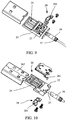
- the end of the rotating joint 22 that is away from the turnover joint 21 is provided with a connecting terminal 25, on which a ground structure 26 is provided.
- the ground structure 26 comprises a ground resilient leg 261 connected to the connecting terminal 25 and connected to a metal shell of the ground structure 26 of the rotating joint 22, and a connecting shaft 24 and the turnover joint 21 are also made of metal material such that an outer structure of the interface in accordance with the present invention can be grounded effectively to form shielding to electromagnetic interference brought by a cable 27 passing through therein.
- the connecting terminal 25 is connected to the data product body 1 via the cable 27, which passes through the connecting shaft 24 and a hole 211 in the turnover joint 21.
- the cable 27 is positioned in the connecting shaft 24 which is concentric with the hole 211 and the hole 211 is concentric with a turnover shaft 23 such that the rotation and turnover of the connecting shaft 24 and the turnover shaft 23 have minimal effect on the cable 27.
- the connecting terminal 25 is provided with a securing structure 28 at a position close to the connecting shaft 24.
- a tablet 281 is pressed against the connecting shaft 24 to secure the connecting shaft 24 to the connecting terminal 25.
- the connecting shaft 24 is fixedly connected to the rotating joint 22, and rotatively connected to the turnover joint 21. As the connecting shaft 24 rotates, both the connecting terminal 25 and the connecting shaft 24 rotate the table 27 so as to reduce a pulling force exerted by the cable 27 on a bonding pad in the connecting terminal 58 to improve the stability and reliability of communication and increase lifetime of the USB interface in accordance with the present invention.
- the turnover joint 21 and the rotating joint 22 are used such that when a data product is plugged into an electronic product, a variety of different position relationships may be generated with respect to the electronic product. These position relationships are very flexible and may be selected according to different practical requirements.
- the ground structure 26 is provided on the connecting terminal 25 and is fixed, and a movable connection between the connecting shaft 24 and the turnover joint 21 may be used to effectively improve the reliability and stability of communication.
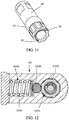
- a turnover-in-place structure 3 which comprises turnover grooves 31, a turnover-in-place ball 32 and a turnover-in-place spring 33 as shown in FIG. 12 , is positioned in the turnover joint 21.
- a total of 8 turnover grooves 31 are evenly provided on the surface of the connecting shaft 23 to guarantee that a turnover angle terminates at 45°.
- Internal surfaces of the turnover grooves 31 are smooth, and depths of the grooves should be determined based on the size of the turnover-in-place ball 32.
- the grooves may be processed as through grooves.
- the turnover-in-place ball 32 is provided in a turnover-in-place pore canal 34 connected to the turnover shaft 23. Two ends of the turnover-in-place ball 32 abut against the turnover-in-place grooves 31 and the turnover-in-place spring 33, respectively.
- the turnover-in-place ball 32 can be placed partially in the turnover grooves 31. During turnover, the turnover-in-place ball 32 can rotate with the turnover-in-place pore canal 34 relative to the turnover grooves 31.
- the turnover-in-place spring 33 is positioned in the turnover-in-place pore canal 34. One end of the turnover-in-place spring 33 is fixed, and the other end pushes the turnover-in-place ball 32 through a connector. The turnover-in-place spring 33 exerts a reset force on the turnover-in-place ball 32, so as to achieve the turnover-in-place termination function.
- a rotating-in-place structure 4 which is the same as the turnover-in-place structure 3, as shown in FIG. 12 , is positioned between the connecting shaft 24 and the turnover joint 21.
- the connecting shaft 24 and the rotating-in-place structure 4 are shown in FIG. 11 .
- the rotating-in-place structure 4 comprises rotating grooves 41, a rotating-in-place ball 42 and a rotating-in-place spring 43.
- a total of 8 rotating grooves 41 are evenly provided on the surface of the rotating joint 24 to guarantee that a rotating angle terminates at 45°. Internal surfaces of the rotating grooves 41 are smooth, and depths of the grooves should be determined based on the size of the rotating-in-place ball 42. For the sake of convenience, the grooves may be processed as through grooves.
- the rotating-in-place ball 42 is provided in a rotating-in-place pore canal 44 connected to the rotating joint 24. Two ends of the rotating-in-place ball 42 abut against the rotating-in-place grooves 41 and the rotating-in-place spring 43, respectively.
- the rotating-in-place ball 42 can be placed partially in the rotating grooves 41. During rotation, the rotating-in-place ball 42 can rotate with the rotating-in-place pore canal 44 relative to the rotating grooves 41.
- the rotating-in-place spring 43 is positioned in the rotating-in-place pore canal 44. One end of the rotating-in-place spring 43 is fixed, and the other end pushes the rotating-in-place ball 42 through a connector. The rotating-in-place spring 43 exerts a reset force on the rotating-in-place ball 42, so as to achieve the rotating-in-place termination function.
- the in-place structure whether the turnover-in-place structure 3 or the rotating-in-place 4, can generate a pause when turning over or rotating in accordance with the present invention such that users can have obvious hand feeling.
- a position limiting structure 29 for limiting a rotating angle of the rotating joint 22 relative to the turnover joint 21 is positioned between the connecting shaft 24 and the turnover joint 21.
- the maximum rotating angle limited by the position limiting structure 29 is 90° to avoid too large left and right rotation while achieving rotation of one cycle.
- this position limiting structure 29 can be implemented by providing a position limiting platform on the connecting shaft 24. When the connecting shaft 24 rotates relative to the turnover joint 21, the position limiting platform can limit the rotation angle.
- the position limiting structure 29 is positioned between the connecting shaft 24 and the turnover joint 21 so as to effectively limit the rotating angle of the rotating joint 22 relative to the turnover joint 21, and avoid winding and breaking of a communication cable 27 due to over-rotation of the rotating joint, causing unnecessary losses.
- the present invention also provides a data product with a USB interface comprising a data product body 1 and a USB interface 2.
- a trough 11 matching the USB interface 2 is provided in a corresponding position in the data product body 1 to rotate and retract the USB interface 2 into the trough 11 conveniently in a retraction state such that the data product is beautiful and portable and the USB interface 2 can be protected.
- the rotating joint 22 can rotate relative to the turnover joint 21 such that users can conveniently select a plug-in angle of the data product; and the turnover joint 21 can turn over relative to the data product body 1 such that the users can conveniently adjust the angle of the data product.
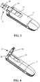
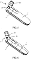
- FIGs. 1-7 show the flexible use and the extremely strong adaptive capability of the data product in accordance with the present invention and can be used in all kinds of narrow spaces. Moreover, these different usage states can improve the beauty of the data product in accordance with the present invention and the interest of the users.
- the cable 17 comprises four coaxial cables coated with a shielding material. This structure can be used to further improve shielding capability.
- a turnover joint and a rotating joint are used such that when a data product is plugged into an electronic product, a variety of different position relationships may be generated with respect to the electronic product.
- the position relationships are very flexible and may be selected according to different practical requirements.
- a ground structure is provided on a connecting terminal and is fixed, and a movable connection between a connecting shaft and the turnover joint may be used to effectively improve the reliability and stability of communication.
- in-place structures are used within the turnover joint as well as between the connecting shaft and the turnover joint so as to facilitate rotating-in-place and turnover-in-place in the data product in accordance with the present invention, extend the usage function, and increase the stability of in-place in use.
- a position limiting structure is positioned between the connecting shaft and the turnover joint so as to effectively limit a rotating angle of the rotating joint relative to the turnover joint, and avoid winding and breaking of a communication cable due to over-rotation of the rotating joint, causing unnecessary losses.
Landscapes
- Details Of Connecting Devices For Male And Female Coupling (AREA)
- Arrangements For Transmission Of Measured Signals (AREA)
Claims (7)
- Schnittstelle für den universellen seriellen Bus USB, die ein Umklappverbindungsstück (21), ein Drehverbindungsstück (22) und eine Verbindungswelle (24), welche das Umklappverbindungsstück (21) mit dem Drehverbindungsstück (22) verbindet, umfasst; wobeiein Ende des Umklappverbindungsstücks (21) mit einem Datenproduktgehäuse (1) verbunden ist und das andere Ende mit dem Drehverbindungsstück (22) verbunden ist; unddas Ende des Drehverbindungsstücks (22), das sich entfernt von dem Umklappverbindungsstück (21) befindet, mit einem Verbindungsanschluss (25) versehen ist, der über ein Kabel (27) mit dem Datenproduktgehäuse (1) verbunden ist; wobei das Drehverbindungsstück (22) relativ zu dem Umklappverbindungsstück (21) drehbar ist,wobei das Umklappverbindungsstück (21) mit dem Datenproduktgehäuse (1) über eine Umklappwelle (23) verbunden ist und die Verbindungswelle (24) mit dem Drehverbindungsstück (22) starr verbunden ist und mit dem Umklappverbindungsstück (21) drehbar verbunden ist,dadurch gekennzeichnet, dass
eine Struktur (3) zum Umklappen auf der Stelle in dem Umklappverbindungsstück (21) positioniert ist und umfasst:Umklapprillen (31), die an einer Oberfläche der Umklappwelle (23) bereitgestellt sind;eine Kugel (32) zum Umklappen auf der Stelle, deren Gestalt zu derjenigen der Umklapprillen (31) passt und die in einem Porenkanal (34) zum Umklappen auf der Stelle bereitgestellt ist, der mit der Umklappwelle (23) verbunden ist, wobei zwei Enden der Kugel (32) zum Umklappen auf der Stelle an die Rillen (31) zum Umklappen auf der Stelle bzw. an eine Feder (33) zum Umklappen auf der Stelle angrenzen; unddie Feder (33) zum Umklappen auf der Stelle in dem Porenkanal (34) zum Umklappen auf der Stelle positioniert ist, wobei ein Ende der Feder (33) zum Umklappen auf der Stelle befestigt ist und das andere Ende die Kugel (32) zum Umklappen auf der Stelle durch einen Verbindungsgang drückt. - USB-Schnittstelle nach Anspruch 1,
wobei eine Massestruktur (26) an dem Verbindungsanschluss (25) bereitgestellt ist, wobei die Massestruktur (26) einen elastischen Masseschenkel (261) umfasst, wobei der elastische Masseschenkel (261) mit dem Verbindungsanschluss (25) verbunden ist und mit einer Metallhülle der Massestruktur (26) des Drehverbindungsstücks (22) verbunden ist, und wobei die Verbindungswelle (24) und das Umklappverbindungsstück (21) ebenfalls aus einem Metallmaterial bestehen. - USB-Schnittstelle nach Anspruch 1,
wobei das Kabel (27) mit dem Umklappverbindungsstück (21) durch die Verbindungswelle (24) hindurch verbunden ist und mit einer Befestigungsstruktur (28) versehen ist, die zum Befestigen des Kabels (27) an einer Position nahe bei dem Verbindungsanschluss (25) verwendet wird. - USB-Schnittstelle nach Anspruch 1,
wobei eine Struktur (4) zum Drehen auf der Stelle zwischen der Verbindungswelle (24) und dem Umklappverbindungsstück (21) positioniert ist und umfasst:Drehrillen (41), die an einer Oberfläche der Drehwelle (24) vorgesehen sind;eine Kugel (42) zum Drehen auf der Stelle, deren Gestalt zu derjenigen der Drehrillen (41) passt und die in einem Porenkanal (44) zum Drehen auf der Stelle bereitgestellt ist, der mit der Verbindungswelle (24) verbunden ist, wobei zwei Enden der Kugel (42) zum Drehen auf der Stelle an die Rillen (41) zum Drehen auf der Stelle bzw. an eine Feder (43) zum Drehen auf der Stelle angrenzen; undwobei die Feder (43) zum Drehen auf der Stelle in dem Porenkanal (44) zum Drehen auf der Stelle positioniert ist, wobei ein Ende der Feder (43) zum Drehen auf der Stelle befestigt ist und das andere Ende die Kugel (42) zum Drehen auf der Stelle durch einen Verbindungsgang drückt. - USB-Schnittstelle nach Anspruch 1,
wobei eine Positionsbegrenzungsstruktur (29) zum Begrenzen eines Drehwinkels des Drehverbindungsstücks (22) relativ zu dem Umklappverbindungsstück (21) zwischen der Verbindungswelle (24) und dem Umklappverbindungsstück (21) positioniert ist. - Datenprodukt mit einer Schnittstelle für einen universellen seriellen Bus USB, welches die USB-Schnittstelle (2) nach einem der Ansprüche 1 - 5 und das Datenproduktgehäuse (1) nach einem der Ansprüche 1 - 5 umfasst; wobeieine Mulde (11), die zu der USB-Schnittstelle (2) passt, an einer entsprechenden Position in dem Datenproduktgehäuse (1) vorgesehen ist; unddas Drehverbindungsstück (22) relativ zu dem Datenproduktgehäuse (1) drehbar ist.
- Datenprodukt nach Anspruch 6,
wobei das Kabel (27) vier axiale Leitungen umfasst, die mit einem Abschirmmaterial beschichtet sind.
Applications Claiming Priority (2)
| Application Number | Priority Date | Filing Date | Title |
|---|---|---|---|
| CN201110003256.4A CN102176596B (zh) | 2011-01-07 | 2011-01-07 | 一种usb接口及具有该接口的数据产品 |
| PCT/CN2011/071771 WO2012092726A1 (zh) | 2011-01-07 | 2011-03-14 | 一种usb接口及具有该接口的数据产品 |
Publications (3)
| Publication Number | Publication Date |
|---|---|
| EP2493034A1 EP2493034A1 (de) | 2012-08-29 |
| EP2493034A4 EP2493034A4 (de) | 2014-02-19 |
| EP2493034B1 true EP2493034B1 (de) | 2016-12-07 |
Family
ID=44519714
Family Applications (1)
| Application Number | Title | Priority Date | Filing Date |
|---|---|---|---|
| EP11822878.2A Not-in-force EP2493034B1 (de) | 2011-01-07 | 2011-03-14 | Usb-schnittstelle und datenprodukt mit der schnittstelle |
Country Status (5)
| Country | Link |
|---|---|
| US (1) | US8672693B2 (de) |
| EP (1) | EP2493034B1 (de) |
| CN (1) | CN102176596B (de) |
| AU (1) | AU2011298737B2 (de) |
| WO (1) | WO2012092726A1 (de) |
Families Citing this family (15)
| Publication number | Priority date | Publication date | Assignee | Title |
|---|---|---|---|---|
| CN102646907A (zh) * | 2012-04-19 | 2012-08-22 | 中兴通讯股份有限公司南京分公司 | Usb接口和终端 |
| CN203277925U (zh) | 2013-04-25 | 2013-11-06 | 鸿富锦精密工业(深圳)有限公司 | 具有usb接头的数据产品 |
| CN203232995U (zh) * | 2013-05-09 | 2013-10-09 | 华为终端有限公司 | 高清晰度多媒体hdmi接口插头 |
| US9411366B1 (en) * | 2014-01-13 | 2016-08-09 | Koamtac, Inc. | Mobile device with improved charging capability and casement structure |
| US9401574B2 (en) * | 2014-08-25 | 2016-07-26 | Dell Products L.P. | Information handling system multi-axis power adapter |
| TWM501628U (zh) * | 2014-12-19 | 2015-05-21 | 威剛科技股份有限公司 | 隨身碟裝置 |
| US9419395B1 (en) * | 2015-07-17 | 2016-08-16 | Stephen Morvillo | Swivel joint charging connector |
| CN106207615B (zh) * | 2016-07-29 | 2019-06-07 | 中航光电科技股份有限公司 | 连接器及其锁紧杆组件和锁紧杆 |
| CN106207382B (zh) * | 2016-09-07 | 2023-03-24 | 深圳市龙禧星科技有限公司 | 一种物联卡上网设备 |
| CN107093829A (zh) * | 2017-07-01 | 2017-08-25 | 王茹茹 | 一种usb电连接器的旋动装置 |
| CN112053626B (zh) * | 2019-06-06 | 2023-05-12 | 海信视像科技股份有限公司 | 显示装置 |
| CN111313186B (zh) * | 2020-03-23 | 2025-03-28 | 深圳市艾鹏网络科技有限公司 | 方向可调的网络端头 |
| CN111342306B (zh) * | 2020-04-20 | 2024-04-30 | 深圳市特发信息股份有限公司 | 一种防脱落的高速数据采集设备用数据线连接头 |
| US20230030251A1 (en) * | 2021-07-20 | 2023-02-02 | Nvidia Corporation | Multi-axis power connection and routing |
| US12121150B2 (en) | 2022-01-31 | 2024-10-22 | Plexicam, Inc | Method and apparatus for dynamically mounting a camera in front of a display screen |
Citations (2)
| Publication number | Priority date | Publication date | Assignee | Title |
|---|---|---|---|---|
| EP2096724A1 (de) * | 2008-02-26 | 2009-09-02 | Shenzhen Huawei Communication Technologies Co., Ltd. | USB-Steckverbinder und USB-Gerät |
| CN201562865U (zh) * | 2009-09-29 | 2010-08-25 | 协讯电子(吉安)有限公司 | 一种具有180°旋转功能的转接端口 |
Family Cites Families (20)
| Publication number | Priority date | Publication date | Assignee | Title |
|---|---|---|---|---|
| JP4111769B2 (ja) * | 2002-08-08 | 2008-07-02 | 三洋電機株式会社 | 音声記録装置 |
| US6786743B2 (en) * | 2002-12-09 | 2004-09-07 | Yea Yen Huang | Connecting hub assembly having universal joint |
| DE20312211U1 (de) * | 2003-08-07 | 2003-10-30 | Yueh, Wen Hsiang, Hsinchuang, Taipeh | Schwenkbarer USB-Stecker |
| JP2005091409A (ja) * | 2003-09-12 | 2005-04-07 | Sanyo Electric Co Ltd | 音声記録装置 |
| CN2738529Y (zh) * | 2004-07-01 | 2005-11-02 | 台均科技(深圳)有限公司 | 一种usb接口可以旋转的移动存储装置 |
| TWM271291U (en) * | 2004-10-04 | 2005-07-21 | Inventec Multimedia & Telecom | Connector |
| TWI259629B (en) * | 2004-10-15 | 2006-08-01 | Tul Corp | The means for the universal serial bus hide and swing |
| US7113812B2 (en) * | 2004-11-23 | 2006-09-26 | Universal Scientific Industrial Co., Ltd | Rotatable wireless transceiver device |
| US7066753B1 (en) * | 2005-07-13 | 2006-06-27 | Askey Computer Corp. | Electronic device capable of multidirectional rotation |
| US7510420B2 (en) * | 2007-02-09 | 2009-03-31 | Belkin International, Inc. | Rotating universal serial bus hub |
| CN201064050Y (zh) * | 2007-06-08 | 2008-05-21 | 中兴通讯股份有限公司 | 一种接口可旋转的usb数据卡 |
| CN201134604Y (zh) | 2007-12-29 | 2008-10-15 | 深圳华为通信技术有限公司 | 可偏转usb接口的接头 |
| CN101431548B (zh) * | 2008-11-12 | 2011-06-15 | 上海德门电子科技有限公司 | 一种手机用双翻转轴装置 |
| CN201327940Y (zh) * | 2008-12-10 | 2009-10-14 | 郑志贤 | 插接头可多向转动的传输电连接器 |
| CN201323599Y (zh) * | 2008-12-22 | 2009-10-07 | 深圳华为通信技术有限公司 | 一种无线数据终端设备 |
| CN101609953B (zh) * | 2009-07-08 | 2011-02-09 | 深圳市德仓科技有限公司 | 具有旋转功能的usb接头 |
| CN101604810B (zh) * | 2009-07-08 | 2012-05-30 | 深圳市德仓科技有限公司 | 具有旋转功能的接头装置 |
| CN101609954B (zh) * | 2009-07-16 | 2011-04-06 | 中兴通讯股份有限公司 | 一种双转轴旋转无线网卡 |
| US8125774B2 (en) * | 2010-06-14 | 2012-02-28 | Share Memories, Llc | Portable keepsake storage device with a pivoting sleeve and USB flash drive |
| CN202183466U (zh) * | 2011-01-07 | 2012-04-04 | 中兴通讯股份有限公司 | 一种usb接口及具有该接口的数据产品 |
-
2011
- 2011-01-07 CN CN201110003256.4A patent/CN102176596B/zh not_active Expired - Fee Related
- 2011-03-14 EP EP11822878.2A patent/EP2493034B1/de not_active Not-in-force
- 2011-03-14 AU AU2011298737A patent/AU2011298737B2/en not_active Ceased
- 2011-03-14 WO PCT/CN2011/071771 patent/WO2012092726A1/zh not_active Ceased
- 2011-03-14 US US13/395,231 patent/US8672693B2/en not_active Expired - Fee Related
Patent Citations (2)
| Publication number | Priority date | Publication date | Assignee | Title |
|---|---|---|---|---|
| EP2096724A1 (de) * | 2008-02-26 | 2009-09-02 | Shenzhen Huawei Communication Technologies Co., Ltd. | USB-Steckverbinder und USB-Gerät |
| CN201562865U (zh) * | 2009-09-29 | 2010-08-25 | 协讯电子(吉安)有限公司 | 一种具有180°旋转功能的转接端口 |
Also Published As
| Publication number | Publication date |
|---|---|
| WO2012092726A1 (zh) | 2012-07-12 |
| AU2011298737B2 (en) | 2013-10-31 |
| US20130273759A1 (en) | 2013-10-17 |
| AU2011298737A1 (en) | 2012-07-26 |
| US8672693B2 (en) | 2014-03-18 |
| CN102176596A (zh) | 2011-09-07 |
| EP2493034A1 (de) | 2012-08-29 |
| EP2493034A4 (de) | 2014-02-19 |
| CN102176596B (zh) | 2015-06-10 |
Similar Documents
| Publication | Publication Date | Title |
|---|---|---|
| EP2493034B1 (de) | Usb-schnittstelle und datenprodukt mit der schnittstelle | |
| US20140106623A1 (en) | Transfer plug for a variety of sockets | |
| CN204230586U (zh) | 电源适配器改良结构 | |
| TWM458691U (zh) | 連接器插座(四) | |
| CN103746237A (zh) | 一种可旋转插合连接器 | |
| CN202183466U (zh) | 一种usb接口及具有该接口的数据产品 | |
| US9077119B2 (en) | Anti-noise cable transferring 1 billion-plus bits per second | |
| CN201639073U (zh) | 插头连接装置及连接装置模块 | |
| US20180189217A1 (en) | Techniques for an extendable peripheral port | |
| CN102324676B (zh) | 一种usb接口及具有该接口的数据产品 | |
| CN201066755Y (zh) | 一种插接器的结构 | |
| CN204558779U (zh) | 可防水的电连接装置 | |
| TWM452515U (zh) | 可降低近端串音之連結器結構 | |
| CN201425999Y (zh) | 多向旋转式连接器 | |
| CN203520257U (zh) | 一种具有保护结构的pcmcia卡 | |
| CN210576730U (zh) | 电子设备及其usb组合装置 | |
| CN202058464U (zh) | 一种具有wifi功能的u盘 | |
| CN209434560U (zh) | 一种数据线 | |
| CN220107146U (zh) | 一种旋转式usb插头 | |
| TWM423377U (en) | Power connector | |
| CN202134776U (zh) | 一种90度上下旋转的信号传输线插头 | |
| CN201674738U (zh) | 数据卡 | |
| TWI335301B (de) | ||
| CN210040802U (zh) | Usb连接器、数据线和用于连接到终端上的外接设备 | |
| CN205583334U (zh) | 一种多头数据传输线 |
Legal Events
| Date | Code | Title | Description |
|---|---|---|---|
| PUAI | Public reference made under article 153(3) epc to a published international application that has entered the european phase |
Free format text: ORIGINAL CODE: 0009012 |
|
| 17P | Request for examination filed |
Effective date: 20120313 |
|
| AK | Designated contracting states |
Kind code of ref document: A1 Designated state(s): AL AT BE BG CH CY CZ DE DK EE ES FI FR GB GR HR HU IE IS IT LI LT LU LV MC MK MT NL NO PL PT RO RS SE SI SK SM TR |
|
| RIC1 | Information provided on ipc code assigned before grant |
Ipc: H01R 35/00 20060101AFI20120803BHEP |
|
| RIN1 | Information on inventor provided before grant (corrected) |
Inventor name: LIU, NING |
|
| R17P | Request for examination filed (corrected) |
Effective date: 20120313 |
|
| REG | Reference to a national code |
Ref country code: DE Ref legal event code: R079 Ref document number: 602011033220 Country of ref document: DE Free format text: PREVIOUS MAIN CLASS: H01R0035000000 Ipc: H01R0035040000 |
|
| A4 | Supplementary search report drawn up and despatched |
Effective date: 20140120 |
|
| RIC1 | Information provided on ipc code assigned before grant |
Ipc: H01R 35/04 20060101AFI20140114BHEP |
|
| DAX | Request for extension of the european patent (deleted) | ||
| 17Q | First examination report despatched |
Effective date: 20150115 |
|
| GRAP | Despatch of communication of intention to grant a patent |
Free format text: ORIGINAL CODE: EPIDOSNIGR1 |
|
| INTG | Intention to grant announced |
Effective date: 20160401 |
|
| GRAS | Grant fee paid |
Free format text: ORIGINAL CODE: EPIDOSNIGR3 |
|
| GRAJ | Information related to disapproval of communication of intention to grant by the applicant or resumption of examination proceedings by the epo deleted |
Free format text: ORIGINAL CODE: EPIDOSDIGR1 |
|
| GRAL | Information related to payment of fee for publishing/printing deleted |
Free format text: ORIGINAL CODE: EPIDOSDIGR3 |
|
| INTC | Intention to grant announced (deleted) | ||
| GRAP | Despatch of communication of intention to grant a patent |
Free format text: ORIGINAL CODE: EPIDOSNIGR1 |
|
| INTG | Intention to grant announced |
Effective date: 20160907 |
|
| GRAA | (expected) grant |
Free format text: ORIGINAL CODE: 0009210 |
|
| STAA | Information on the status of an ep patent application or granted ep patent |
Free format text: STATUS: THE PATENT HAS BEEN GRANTED |
|
| AK | Designated contracting states |
Kind code of ref document: B1 Designated state(s): AL AT BE BG CH CY CZ DE DK EE ES FI FR GB GR HR HU IE IS IT LI LT LU LV MC MK MT NL NO PL PT RO RS SE SI SK SM TR |
|
| REG | Reference to a national code |
Ref country code: GB Ref legal event code: FG4D |
|
| REG | Reference to a national code |
Ref country code: CH Ref legal event code: EP Ref country code: AT Ref legal event code: REF Ref document number: 852463 Country of ref document: AT Kind code of ref document: T Effective date: 20161215 |
|
| REG | Reference to a national code |
Ref country code: IE Ref legal event code: FG4D |
|
| REG | Reference to a national code |
Ref country code: DE Ref legal event code: R096 Ref document number: 602011033220 Country of ref document: DE |
|
| REG | Reference to a national code |
Ref country code: FR Ref legal event code: PLFP Year of fee payment: 7 |
|
| PG25 | Lapsed in a contracting state [announced via postgrant information from national office to epo] |
Ref country code: LV Free format text: LAPSE BECAUSE OF FAILURE TO SUBMIT A TRANSLATION OF THE DESCRIPTION OR TO PAY THE FEE WITHIN THE PRESCRIBED TIME-LIMIT Effective date: 20161207 |
|
| REG | Reference to a national code |
Ref country code: LT Ref legal event code: MG4D |
|
| REG | Reference to a national code |
Ref country code: NL Ref legal event code: MP Effective date: 20161207 |
|
| PG25 | Lapsed in a contracting state [announced via postgrant information from national office to epo] |
Ref country code: LT Free format text: LAPSE BECAUSE OF FAILURE TO SUBMIT A TRANSLATION OF THE DESCRIPTION OR TO PAY THE FEE WITHIN THE PRESCRIBED TIME-LIMIT Effective date: 20161207 Ref country code: SE Free format text: LAPSE BECAUSE OF FAILURE TO SUBMIT A TRANSLATION OF THE DESCRIPTION OR TO PAY THE FEE WITHIN THE PRESCRIBED TIME-LIMIT Effective date: 20161207 Ref country code: GR Free format text: LAPSE BECAUSE OF FAILURE TO SUBMIT A TRANSLATION OF THE DESCRIPTION OR TO PAY THE FEE WITHIN THE PRESCRIBED TIME-LIMIT Effective date: 20170308 Ref country code: NO Free format text: LAPSE BECAUSE OF FAILURE TO SUBMIT A TRANSLATION OF THE DESCRIPTION OR TO PAY THE FEE WITHIN THE PRESCRIBED TIME-LIMIT Effective date: 20170307 |
|
| REG | Reference to a national code |
Ref country code: AT Ref legal event code: MK05 Ref document number: 852463 Country of ref document: AT Kind code of ref document: T Effective date: 20161207 |
|
| PG25 | Lapsed in a contracting state [announced via postgrant information from national office to epo] |
Ref country code: RS Free format text: LAPSE BECAUSE OF FAILURE TO SUBMIT A TRANSLATION OF THE DESCRIPTION OR TO PAY THE FEE WITHIN THE PRESCRIBED TIME-LIMIT Effective date: 20161207 Ref country code: FI Free format text: LAPSE BECAUSE OF FAILURE TO SUBMIT A TRANSLATION OF THE DESCRIPTION OR TO PAY THE FEE WITHIN THE PRESCRIBED TIME-LIMIT Effective date: 20161207 Ref country code: HR Free format text: LAPSE BECAUSE OF FAILURE TO SUBMIT A TRANSLATION OF THE DESCRIPTION OR TO PAY THE FEE WITHIN THE PRESCRIBED TIME-LIMIT Effective date: 20161207 Ref country code: ES Free format text: LAPSE BECAUSE OF FAILURE TO SUBMIT A TRANSLATION OF THE DESCRIPTION OR TO PAY THE FEE WITHIN THE PRESCRIBED TIME-LIMIT Effective date: 20161207 |
|
| PG25 | Lapsed in a contracting state [announced via postgrant information from national office to epo] |
Ref country code: NL Free format text: LAPSE BECAUSE OF FAILURE TO SUBMIT A TRANSLATION OF THE DESCRIPTION OR TO PAY THE FEE WITHIN THE PRESCRIBED TIME-LIMIT Effective date: 20161207 |
|
| PG25 | Lapsed in a contracting state [announced via postgrant information from national office to epo] |
Ref country code: SK Free format text: LAPSE BECAUSE OF FAILURE TO SUBMIT A TRANSLATION OF THE DESCRIPTION OR TO PAY THE FEE WITHIN THE PRESCRIBED TIME-LIMIT Effective date: 20161207 Ref country code: IS Free format text: LAPSE BECAUSE OF FAILURE TO SUBMIT A TRANSLATION OF THE DESCRIPTION OR TO PAY THE FEE WITHIN THE PRESCRIBED TIME-LIMIT Effective date: 20170407 Ref country code: CZ Free format text: LAPSE BECAUSE OF FAILURE TO SUBMIT A TRANSLATION OF THE DESCRIPTION OR TO PAY THE FEE WITHIN THE PRESCRIBED TIME-LIMIT Effective date: 20161207 Ref country code: EE Free format text: LAPSE BECAUSE OF FAILURE TO SUBMIT A TRANSLATION OF THE DESCRIPTION OR TO PAY THE FEE WITHIN THE PRESCRIBED TIME-LIMIT Effective date: 20161207 Ref country code: RO Free format text: LAPSE BECAUSE OF FAILURE TO SUBMIT A TRANSLATION OF THE DESCRIPTION OR TO PAY THE FEE WITHIN THE PRESCRIBED TIME-LIMIT Effective date: 20161207 |
|
| PG25 | Lapsed in a contracting state [announced via postgrant information from national office to epo] |
Ref country code: PT Free format text: LAPSE BECAUSE OF FAILURE TO SUBMIT A TRANSLATION OF THE DESCRIPTION OR TO PAY THE FEE WITHIN THE PRESCRIBED TIME-LIMIT Effective date: 20170407 Ref country code: AT Free format text: LAPSE BECAUSE OF FAILURE TO SUBMIT A TRANSLATION OF THE DESCRIPTION OR TO PAY THE FEE WITHIN THE PRESCRIBED TIME-LIMIT Effective date: 20161207 Ref country code: IT Free format text: LAPSE BECAUSE OF FAILURE TO SUBMIT A TRANSLATION OF THE DESCRIPTION OR TO PAY THE FEE WITHIN THE PRESCRIBED TIME-LIMIT Effective date: 20161207 Ref country code: SM Free format text: LAPSE BECAUSE OF FAILURE TO SUBMIT A TRANSLATION OF THE DESCRIPTION OR TO PAY THE FEE WITHIN THE PRESCRIBED TIME-LIMIT Effective date: 20161207 Ref country code: BG Free format text: LAPSE BECAUSE OF FAILURE TO SUBMIT A TRANSLATION OF THE DESCRIPTION OR TO PAY THE FEE WITHIN THE PRESCRIBED TIME-LIMIT Effective date: 20170307 Ref country code: BE Free format text: LAPSE BECAUSE OF FAILURE TO SUBMIT A TRANSLATION OF THE DESCRIPTION OR TO PAY THE FEE WITHIN THE PRESCRIBED TIME-LIMIT Effective date: 20161207 Ref country code: PL Free format text: LAPSE BECAUSE OF FAILURE TO SUBMIT A TRANSLATION OF THE DESCRIPTION OR TO PAY THE FEE WITHIN THE PRESCRIBED TIME-LIMIT Effective date: 20161207 |
|
| REG | Reference to a national code |
Ref country code: DE Ref legal event code: R097 Ref document number: 602011033220 Country of ref document: DE |
|
| PLBE | No opposition filed within time limit |
Free format text: ORIGINAL CODE: 0009261 |
|
| STAA | Information on the status of an ep patent application or granted ep patent |
Free format text: STATUS: NO OPPOSITION FILED WITHIN TIME LIMIT |
|
| REG | Reference to a national code |
Ref country code: CH Ref legal event code: PL |
|
| 26N | No opposition filed |
Effective date: 20170908 |
|
| GBPC | Gb: european patent ceased through non-payment of renewal fee |
Effective date: 20170314 |
|
| PG25 | Lapsed in a contracting state [announced via postgrant information from national office to epo] |
Ref country code: DK Free format text: LAPSE BECAUSE OF FAILURE TO SUBMIT A TRANSLATION OF THE DESCRIPTION OR TO PAY THE FEE WITHIN THE PRESCRIBED TIME-LIMIT Effective date: 20161207 Ref country code: MC Free format text: LAPSE BECAUSE OF FAILURE TO SUBMIT A TRANSLATION OF THE DESCRIPTION OR TO PAY THE FEE WITHIN THE PRESCRIBED TIME-LIMIT Effective date: 20161207 Ref country code: SI Free format text: LAPSE BECAUSE OF FAILURE TO SUBMIT A TRANSLATION OF THE DESCRIPTION OR TO PAY THE FEE WITHIN THE PRESCRIBED TIME-LIMIT Effective date: 20161207 |
|
| REG | Reference to a national code |
Ref country code: IE Ref legal event code: MM4A |
|
| PG25 | Lapsed in a contracting state [announced via postgrant information from national office to epo] |
Ref country code: LU Free format text: LAPSE BECAUSE OF NON-PAYMENT OF DUE FEES Effective date: 20170314 |
|
| PG25 | Lapsed in a contracting state [announced via postgrant information from national office to epo] |
Ref country code: LI Free format text: LAPSE BECAUSE OF NON-PAYMENT OF DUE FEES Effective date: 20170331 Ref country code: CH Free format text: LAPSE BECAUSE OF NON-PAYMENT OF DUE FEES Effective date: 20170331 Ref country code: IE Free format text: LAPSE BECAUSE OF NON-PAYMENT OF DUE FEES Effective date: 20170314 Ref country code: GB Free format text: LAPSE BECAUSE OF NON-PAYMENT OF DUE FEES Effective date: 20170314 |
|
| REG | Reference to a national code |
Ref country code: FR Ref legal event code: PLFP Year of fee payment: 8 |
|
| PG25 | Lapsed in a contracting state [announced via postgrant information from national office to epo] |
Ref country code: MT Free format text: LAPSE BECAUSE OF NON-PAYMENT OF DUE FEES Effective date: 20170314 |
|
| PG25 | Lapsed in a contracting state [announced via postgrant information from national office to epo] |
Ref country code: HU Free format text: LAPSE BECAUSE OF FAILURE TO SUBMIT A TRANSLATION OF THE DESCRIPTION OR TO PAY THE FEE WITHIN THE PRESCRIBED TIME-LIMIT; INVALID AB INITIO Effective date: 20110314 |
|
| PG25 | Lapsed in a contracting state [announced via postgrant information from national office to epo] |
Ref country code: CY Free format text: LAPSE BECAUSE OF NON-PAYMENT OF DUE FEES Effective date: 20161207 |
|
| PG25 | Lapsed in a contracting state [announced via postgrant information from national office to epo] |
Ref country code: MK Free format text: LAPSE BECAUSE OF FAILURE TO SUBMIT A TRANSLATION OF THE DESCRIPTION OR TO PAY THE FEE WITHIN THE PRESCRIBED TIME-LIMIT Effective date: 20161207 |
|
| PG25 | Lapsed in a contracting state [announced via postgrant information from national office to epo] |
Ref country code: TR Free format text: LAPSE BECAUSE OF FAILURE TO SUBMIT A TRANSLATION OF THE DESCRIPTION OR TO PAY THE FEE WITHIN THE PRESCRIBED TIME-LIMIT Effective date: 20161207 |
|
| PGFP | Annual fee paid to national office [announced via postgrant information from national office to epo] |
Ref country code: DE Payment date: 20200303 Year of fee payment: 10 |
|
| PGFP | Annual fee paid to national office [announced via postgrant information from national office to epo] |
Ref country code: FR Payment date: 20200214 Year of fee payment: 10 |
|
| PG25 | Lapsed in a contracting state [announced via postgrant information from national office to epo] |
Ref country code: AL Free format text: LAPSE BECAUSE OF FAILURE TO SUBMIT A TRANSLATION OF THE DESCRIPTION OR TO PAY THE FEE WITHIN THE PRESCRIBED TIME-LIMIT Effective date: 20161207 |
|
| REG | Reference to a national code |
Ref country code: DE Ref legal event code: R119 Ref document number: 602011033220 Country of ref document: DE |
|
| PG25 | Lapsed in a contracting state [announced via postgrant information from national office to epo] |
Ref country code: FR Free format text: LAPSE BECAUSE OF NON-PAYMENT OF DUE FEES Effective date: 20210331 Ref country code: DE Free format text: LAPSE BECAUSE OF NON-PAYMENT OF DUE FEES Effective date: 20211001 |