EP2492939A2 - Circuit breaker with arc extinguishing mechanism - Google Patents
Circuit breaker with arc extinguishing mechanism Download PDFInfo
- Publication number
- EP2492939A2 EP2492939A2 EP12151736A EP12151736A EP2492939A2 EP 2492939 A2 EP2492939 A2 EP 2492939A2 EP 12151736 A EP12151736 A EP 12151736A EP 12151736 A EP12151736 A EP 12151736A EP 2492939 A2 EP2492939 A2 EP 2492939A2
- Authority
- EP
- European Patent Office
- Prior art keywords
- arc
- grids
- insulating plates
- circuit breaker
- mover
- Prior art date
- Legal status (The legal status is an assumption and is not a legal conclusion. Google has not performed a legal analysis and makes no representation as to the accuracy of the status listed.)
- Granted
Links
Images

Classifications
-
- H—ELECTRICITY
- H01—ELECTRIC ELEMENTS
- H01H—ELECTRIC SWITCHES; RELAYS; SELECTORS; EMERGENCY PROTECTIVE DEVICES
- H01H73/00—Protective overload circuit-breaking switches in which excess current opens the contacts by automatic release of mechanical energy stored by previous operation of a hand reset mechanism
- H01H73/02—Details
- H01H73/18—Means for extinguishing or suppressing arc
-
- H—ELECTRICITY
- H01—ELECTRIC ELEMENTS
- H01H—ELECTRIC SWITCHES; RELAYS; SELECTORS; EMERGENCY PROTECTIVE DEVICES
- H01H9/00—Details of switching devices, not covered by groups H01H1/00 - H01H7/00
- H01H9/30—Means for extinguishing or preventing arc between current-carrying parts
- H01H9/34—Stationary parts for restricting or subdividing the arc, e.g. barrier plate
- H01H9/346—Details concerning the arc formation chamber
-
- H—ELECTRICITY
- H01—ELECTRIC ELEMENTS
- H01H—ELECTRIC SWITCHES; RELAYS; SELECTORS; EMERGENCY PROTECTIVE DEVICES
- H01H71/00—Details of the protective switches or relays covered by groups H01H73/00 - H01H83/00
- H01H71/10—Operating or release mechanisms
- H01H71/12—Automatic release mechanisms with or without manual release
- H01H71/24—Electromagnetic mechanisms
- H01H71/38—Electromagnetic mechanisms wherein the magnet coil also acts as arc blow-out device
-
- H—ELECTRICITY
- H01—ELECTRIC ELEMENTS
- H01H—ELECTRIC SWITCHES; RELAYS; SELECTORS; EMERGENCY PROTECTIVE DEVICES
- H01H9/00—Details of switching devices, not covered by groups H01H1/00 - H01H7/00
- H01H9/30—Means for extinguishing or preventing arc between current-carrying parts
- H01H9/40—Multiple main contacts for the purpose of dividing the current through, or potential drop along, the arc
-
- H—ELECTRICITY
- H01—ELECTRIC ELEMENTS
- H01H—ELECTRIC SWITCHES; RELAYS; SELECTORS; EMERGENCY PROTECTIVE DEVICES
- H01H9/00—Details of switching devices, not covered by groups H01H1/00 - H01H7/00
- H01H9/30—Means for extinguishing or preventing arc between current-carrying parts
- H01H9/46—Means for extinguishing or preventing arc between current-carrying parts using arcing horns
Definitions
- This specification relates to a circuit breaker with an arc extinguishing mechanism, and particularly, to a circuit breaker with an arc extinguishing mechanism for extinguishing arc generated when a movable contactor is separated from a stationary contactor due to a fault current.
- a circuit breaker is an electric device for protecting a circuit and a line by automatically breaking such circuit or line upon occurrences of an electric overload state or a short-circuit state.
- current flowing over an electric circuit is generally divided into a rated current and a fault current which flows due to a breakdown like short-circuit, grounding, etc.
- the fault current is drastically larger than the rated current, so it is difficult to be cut off. Accordingly, the circuit breaker is designed to block both the rated current and the fault current.
- a rated switch is able to merely block a current, which is as low as the rated current, so it is distinguished from the circuit breaker.
- An electric power system includes a power generator, a transformer, a power transmission line and the like. When desiring to suspend some of them, a current of the power generator or power transmission line desired to be suspended is blocked by a circuit breaker such that the power generator or power transmission line can be isolated from the electric power system. Also, when a breakdown such as short-circuit or grounding is caused in the system, an extremely large fault current flows over the system. If the system is left in that state, it may aggravate damage on the broken component or portion and the other may also be out of order due to large current. Thus, the circuit breaker is used for blocking the broken portion.
- the circuit breaker exhibits more excellent current imitation when it has superior arc extinguishing capability and takes a shorter time to break current.
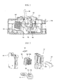
- FIG. 1 is a schematic view showing a structure of the related art circuit breaker
- FIG. 2 is a disassembled perspective view showing a structure of an arc extinguishing mechanism of the related art circuit breaker
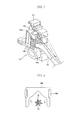
- FIG. 3 is a view showing operations of the related art arc extinguishing mechanism
- FIG. 4 is a planar view showing an exhausting direction of arc generated from the related art circuit breaker.
- the related art circuit breaker 100 includes a first stator 110 implemented as a conductor to induce current to flow inwardly, a mover 130 selectively contactable with the first stator 110 by a mechanical operation of a switching mechanism 120, an arc extinguishing mechanism 140 to extinguish arc generated between contact points of the mover 130 and the first stator 110, a connecting contactor 150 coupled with one end of the mover 130, a second stator 160 connected to the connector 150 and implemented as a conductor to induce a current to flow outwardly, a trip mechanism 170 to operate the switching mechanism 120 by detecting a generation of a fault current and abnormal current, and a handle 180 to manually drive the switching mechanism 120.
- a first stator 110 implemented as a conductor to induce current to flow inwardly
- a mover 130 selectively contactable with the first stator 110 by a mechanical operation of a switching mechanism 120
- an arc extinguishing mechanism 140 to extinguish arc generated between contact points of the mover 130 and the
- the arc extinguishing mechanism 140 of the related art circuit breaker 100 includes a first stator 141 and a mover 142.
- a stationary contact 141 a and a movable contact 142a are brazed at the first stator 141 and the mover 142, respectively.
- a rear end of the stationary contact 141a is embossed to act as an arc runner 141 b.
- a position adjacent to the first stator 141 and the mover 142 is shown having an arc chute 143.
- the arc chute 143 includes a plurality of grids 143a made of a metal having ferromagnetism, and fixing plates 143b made of an insulating material to fix the grids 143a.
- the first stator 141, the upper grid 144 and the arc chute 143 are integrally assembled together and mounted in a case 145 made of an insulating material.
- the stationary contact 141a and the movable contact 142a remain contacted while a rated current flows.
- a fault current such as overcurrent or short-circuit current
- the mover 142 is separated due to an electromagnetic repulsive force, which is generated between the stationary contact 141a and the movable contact 142a, thereby cutting off current.
- arc is generated between the stationary contact 141a and the movable contact 142a.
- the generated arc is induced to the arc runner 141b to flow to the arc chute 143.
- the arc is segmented by the grids 143a of the arc chute 143, thereby increasing an arc voltage to be higher than a power source voltage, which limits the short-circuit current and results in extinguishing arc. Also, the arc extinguishing effect is obtained by arc extinguishing gas, which is generated from the insulating plates 143b which fix the grids 143b of the arc chute 143.
- the arc extinguishing mechanism of the related art circuit breaker extinguishes arc merely by segmenting arc into various directions a, b, c by the grids 143a and cooling arc, so it takes a long time to extinguish arc and also arc heat gas is reversely exhausted in a direction d where the rotational shaft of the mover 142 is installed, which causes problems of arc reignition and damage on the movable contact 142a and the stationary contact 141 a.
- an aspect of the detailed description is to provide an arc extinguishing mechanism for a circuit breaker capable of uniformly distributing arc, generated upon breaking a fault current, into grids so as to improve arc extinguishing efficiency.
- a circuit breaker including a plurality of grids disposed in a longitudinal direction, each having protruding portions at both ends thereof so as to define a space therebetween, a fixing portion to support the grids, insulating plates fixed to both sides of the grids, a stator located below the grids, the stator including an arc runner and a stationary contact disposed at an upper side of the arc runner, and a mover contactable with or separated from the stationary contact with moving up and down within the space, wherein an interval between the insulating plates within the space is shorter than a width of the mover.
- the interval between the pair of insulating plates can be shorter than a width of the mover, namely, end portions of the insulating plates can protrude into the space, so as to allow the generated arc to be more smoothly introduced into the grids and simultaneously increase an amount of arc extinguishing gas generated by the insulating plates, thereby improving an arc extinguishing performance.
- the insulating plates may include first insulating plates disposed at both sides of the grids, and second insulating plates coupled to the first insulating plates and extending into the space.
- Each of the second insulating plates may include a coupling portion coupled to the first insulating plate, and an inclined portion extending from the coupling portion toward the grids with an inclination.
- the second insulating plates may be located between the protruding portions of the grids and the mover.
- the interval between the insulating plates within the space can be shorter than a width of the arc runner, to allow more arc to be introduced into the grids.
- arc generated during a breaking operation can be introduced more into grids and a contact area between the arc and the insulating plates can be increased, resulting in enhancement of arc extinguishing efficiency.
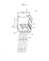
- FIG. 5 is a perspective view showing one exemplary embodiment of a circuit breaker in accordance with this specification
- FIG. 6 is a sectional view of the one exemplary embodiment shown in FIG. 5
- FIG. 7 is a planar view of the one exemplary embodiment shown in FIG. 5 .
- a circuit breaker 10 in accordance with the exemplary embodiment may include plural sheets of grids 20 laminated in a longitudinal (vertical) direction with predetermined intervals.
- the grid 20 may be made of a metal having ferromagnetism.
- Protruding portion 22 may be formed at both ends at the front of each grid 20 based on FIG. 5 .
- a space formed between the protruding portions 22 may define an arc extinguishing space 24 in which arc generated due to a longitudinal (vertical, up-and-down) motion of a mover to be explained later is diffused and extinguished.
- an upper grid 26 may be located on the top of the grid 20. The upper grid 26 may obscure the upper side of the arc extinguishing space 24 to prevent the generated arc from being leaked out of the top of the grid 20.
- a fixing portion 30 may be installed at the rear of the grids 20.
- the fixing portion 30 may serve to fix the grids 20 such that the grids 20 can remain in the fixed state with the predetermined intervals.
- the fixing portion 30 may be secured with a circuit breaker main body (not shown).
- First insulating plates 40 may be fixed to both side surfaces of the girds 20.
- the first insulating plates 40 may prevent arc leakage to the outside in cooperation with the upper grid 26 and also serve to fix the grids 20.
- the first insulating plates 40 may be made of a material, which is able to generate arc extinguishing gas when contacting arc, so as to rapidly extinguish such arc.
- the first insulating plates 40 may be formed longer than the grids 20 such that their front sides can protrude from the front sides of the grids 20.
- Second insulating plates 50 may be fixed onto the protruded portions.
- Each of the second insulating plates 50 as shown in FIG. 5 , may include a coupling portion 52 coupled to the first insulating plate 40, and an inclined portion 54 extending from the coupling portion 52 with being inclined to the inside of the arc extinguishing space. Hence, an interval a between ends of the inclined portions 54 may be shorter than an interval between the coupling portions 52.
- a mover 60 may be installed at the front of the second insulating plates 50.
- the mover 60 may have the same structure as the mover of the typical circuit breaker.
- the mover 60 may include a plurality of movable contactors 62 disposed in series.
- a stator 70 may be disposed below the mover 60.
- the stator 70 may include a stationary contact 72 contacting the mover 60, and an arc runner 74 to induce arc generated during a breaking process.
- a stationary contact 72 contacting the mover 60
- an arc runner 74 to induce arc generated during a breaking process.
- the generated arc extinguishing gas compresses and elongates an arc column by pressure, which is instantaneously rapidly risen in the arc extinguishing space, so as to render an arc voltage high, thereby improving a current limitation performance (efficiency).
- the arc then rapidly moves into the grids 20 by an attractive force and pressure by a magnetism generated by the grids 20, so as to be segmented and cooled.
- the second insulating plates 50 protrude into the arc extinguishing space, so the arc can generate the arc extinguishing gas by contacting the insulating plates 50 more rapidly.
- the inclined portions 54 of the second insulating plates 50 can additionally shield the arc extinguishing space. Accordingly, upon the arc generation, pressure within the arc extinguishing space can be further increased, which can make the arc diffused more rapidly into the grids 20.
- the inclined portions 54 of the second insulating plates 50 can also prevent the arc from being reversely exhausted toward the mover 60. Consequently, metal particles, which are melted by heat gas and arc heat within the arc extinguishing space can be prevented from being exhausted toward the mover 60. This may result in prevention of damages of the stationary contact 72 and the mover 60 and prevention of reignition due to the reverse exhaust of the arc, which is ended up with improvement of a current limitation effect.
Landscapes
- Physics & Mathematics (AREA)
- Electromagnetism (AREA)
- Breakers (AREA)
- Arc-Extinguishing Devices That Are Switches (AREA)
Abstract
Description
- This specification relates to a circuit breaker with an arc extinguishing mechanism, and particularly, to a circuit breaker with an arc extinguishing mechanism for extinguishing arc generated when a movable contactor is separated from a stationary contactor due to a fault current.
- A circuit breaker is an electric device for protecting a circuit and a line by automatically breaking such circuit or line upon occurrences of an electric overload state or a short-circuit state. In general, current flowing over an electric circuit is generally divided into a rated current and a fault current which flows due to a breakdown like short-circuit, grounding, etc.
- The fault current is drastically larger than the rated current, so it is difficult to be cut off. Accordingly, the circuit breaker is designed to block both the rated current and the fault current. A rated switch is able to merely block a current, which is as low as the rated current, so it is distinguished from the circuit breaker. An electric power system includes a power generator, a transformer, a power transmission line and the like. When desiring to suspend some of them, a current of the power generator or power transmission line desired to be suspended is blocked by a circuit breaker such that the power generator or power transmission line can be isolated from the electric power system. Also, when a breakdown such as short-circuit or grounding is caused in the system, an extremely large fault current flows over the system. If the system is left in that state, it may aggravate damage on the broken component or portion and the other may also be out of order due to large current. Thus, the circuit breaker is used for blocking the broken portion.
- In general, the circuit breaker exhibits more excellent current imitation when it has superior arc extinguishing capability and takes a shorter time to break current.
-
FIG. 1 is a schematic view showing a structure of the related art circuit breaker,FIG. 2 is a disassembled perspective view showing a structure of an arc extinguishing mechanism of the related art circuit breaker,FIG. 3 is a view showing operations of the related art arc extinguishing mechanism, andFIG. 4 is a planar view showing an exhausting direction of arc generated from the related art circuit breaker. - As shown in
FIG. 1 , the relatedart circuit breaker 100 includes afirst stator 110 implemented as a conductor to induce current to flow inwardly, amover 130 selectively contactable with thefirst stator 110 by a mechanical operation of aswitching mechanism 120, anarc extinguishing mechanism 140 to extinguish arc generated between contact points of themover 130 and thefirst stator 110, aconnecting contactor 150 coupled with one end of themover 130, asecond stator 160 connected to theconnector 150 and implemented as a conductor to induce a current to flow outwardly, atrip mechanism 170 to operate theswitching mechanism 120 by detecting a generation of a fault current and abnormal current, and ahandle 180 to manually drive theswitching mechanism 120. - As shown in
FIG. 2 , thearc extinguishing mechanism 140 of the relatedart circuit breaker 100 includes afirst stator 141 and amover 142. Astationary contact 141 a and amovable contact 142a are brazed at thefirst stator 141 and themover 142, respectively. A rear end of thestationary contact 141a is embossed to act as anarc runner 141 b. A position adjacent to thefirst stator 141 and themover 142 is shown having anarc chute 143. Thearc chute 143 includes a plurality ofgrids 143a made of a metal having ferromagnetism, andfixing plates 143b made of an insulating material to fix thegrids 143a. Thefirst stator 141, theupper grid 144 and thearc chute 143 are integrally assembled together and mounted in acase 145 made of an insulating material. - An operation of the arc extinguishing mechanism of the related art circuit breaker is described as follows.
- Referring to
FIG. 3 , in the relatedart circuit breaker 100, thestationary contact 141a and themovable contact 142a remain contacted while a rated current flows. However, when a fault current such as overcurrent or short-circuit current, is generated, themover 142 is separated due to an electromagnetic repulsive force, which is generated between thestationary contact 141a and themovable contact 142a, thereby cutting off current. When themover 142 is separated, arc is generated between thestationary contact 141a and themovable contact 142a. The generated arc is induced to thearc runner 141b to flow to thearc chute 143. The arc is segmented by thegrids 143a of thearc chute 143, thereby increasing an arc voltage to be higher than a power source voltage, which limits the short-circuit current and results in extinguishing arc. Also, the arc extinguishing effect is obtained by arc extinguishing gas, which is generated from theinsulating plates 143b which fix thegrids 143b of thearc chute 143. - However, in the arc extinguishing mechanism of the related art circuit breaker, after arc generated due to a rotary motion of the
mover 142 flows to thearc chute 143 through thearc runner 141 b, when the arc is elongated within thearc chute 143, an arc column is not induced up to theupper grid 144, it is impossible to obtain a significant increase in an arc voltage. Also, theinsulating plates 143b for supporting thegrids 143a are unable to generate significant extinguishing gas due to arc energy. Hence, it is impossible to expect an increase in the arc voltage in response to an increase in pressure. Also, referring toFIG. 4 , the arc extinguishing mechanism of the related art circuit breaker extinguishes arc merely by segmenting arc into various directions a, b, c by thegrids 143a and cooling arc, so it takes a long time to extinguish arc and also arc heat gas is reversely exhausted in a direction d where the rotational shaft of themover 142 is installed, which causes problems of arc reignition and damage on themovable contact 142a and thestationary contact 141 a. - Therefore, to address the drawbacks of the related art, an aspect of the detailed description is to provide an arc extinguishing mechanism for a circuit breaker capable of uniformly distributing arc, generated upon breaking a fault current, into grids so as to improve arc extinguishing efficiency.
- To achieve these and other advantages and in accordance with the purpose of this specification, as embodied and broadly described herein, there is provided a circuit breaker including a plurality of grids disposed in a longitudinal direction, each having protruding portions at both ends thereof so as to define a space therebetween, a fixing portion to support the grids, insulating plates fixed to both sides of the grids, a stator located below the grids, the stator including an arc runner and a stationary contact disposed at an upper side of the arc runner, and a mover contactable with or separated from the stationary contact with moving up and down within the space, wherein an interval between the insulating plates within the space is shorter than a width of the mover.
- In accordance with the aspect, the interval between the pair of insulating plates can be shorter than a width of the mover, namely, end portions of the insulating plates can protrude into the space, so as to allow the generated arc to be more smoothly introduced into the grids and simultaneously increase an amount of arc extinguishing gas generated by the insulating plates, thereby improving an arc extinguishing performance.
- Here, the insulating plates may include first insulating plates disposed at both sides of the grids, and second insulating plates coupled to the first insulating plates and extending into the space. Each of the second insulating plates may include a coupling portion coupled to the first insulating plate, and an inclined portion extending from the coupling portion toward the grids with an inclination.
- Also, the second insulating plates may be located between the protruding portions of the grids and the mover.
- In addition, the interval between the insulating plates within the space can be shorter than a width of the arc runner, to allow more arc to be introduced into the grids.
- In accordance with the aspects of the present disclosure with the configuration, arc generated during a breaking operation can be introduced more into grids and a contact area between the arc and the insulating plates can be increased, resulting in enhancement of arc extinguishing efficiency.
- Further scope of applicability of the present application will become more apparent from the detailed description given hereinafter. However, it should be understood that the detailed description and specific examples, while indicating preferred embodiments of the invention, are given by way of illustration only, since various changes and modifications within the spirit and scope of the invention will become apparent to those skilled in the art from the detailed description.
- The accompanying drawings, which are included to provide a further understanding of the invention and are incorporated in and constitute a part of this specification, illustrate exemplary embodiments and together with the description serve to explain the principles of the invention.
- In the drawings:
-
FIG. 1 is a sectional view schematically showing a structure of the related art circuit breaker; -
FIG. 2 is a disassembled perspective view showing a structure of an arc extinguishing mechanism of the related art circuit breaker; -
FIG. 3 is a view showing operations of the related art arc extinguishing mechanism; -
FIG. 4 is a planar view showing an exhausting direction of arc generated from the related art circuit breaker; -
FIG. 5 is a perspective view showing one exemplary embodiment of a circuit breaker in accordance with this specification; -
FIG. 6 is a sectional view of the one exemplary embodiment shown inFIG. 5 ; and -
FIG. 7 is a planar view of the one exemplary embodiment shown inFIG. 5 . - Description will now be given in detail of a circuit breaker in accordance with the exemplary embodiments, with reference to the accompanying drawings. For the sake of brief description with reference to the drawings, the same or equivalent components will be provided with the same reference numbers, and description thereof will not be repeated.
-
FIG. 5 is a perspective view showing one exemplary embodiment of a circuit breaker in accordance with this specification,FIG. 6 is a sectional view of the one exemplary embodiment shown inFIG. 5 , andFIG. 7 is a planar view of the one exemplary embodiment shown inFIG. 5 . - Referring to
FIGS. 5 to 7 , acircuit breaker 10 in accordance with the exemplary embodiment may include plural sheets ofgrids 20 laminated in a longitudinal (vertical) direction with predetermined intervals. - The
grid 20 may be made of a metal having ferromagnetism. Protrudingportion 22 may be formed at both ends at the front of eachgrid 20 based onFIG. 5 . A space formed between theprotruding portions 22 may define anarc extinguishing space 24 in which arc generated due to a longitudinal (vertical, up-and-down) motion of a mover to be explained later is diffused and extinguished. Here, anupper grid 26 may be located on the top of thegrid 20. Theupper grid 26 may obscure the upper side of thearc extinguishing space 24 to prevent the generated arc from being leaked out of the top of thegrid 20. - A fixing
portion 30 may be installed at the rear of thegrids 20. The fixingportion 30 may serve to fix thegrids 20 such that thegrids 20 can remain in the fixed state with the predetermined intervals. In addition, the fixingportion 30 may be secured with a circuit breaker main body (not shown). - First insulating
plates 40 may be fixed to both side surfaces of thegirds 20. The first insulatingplates 40 may prevent arc leakage to the outside in cooperation with theupper grid 26 and also serve to fix thegrids 20. The first insulatingplates 40 may be made of a material, which is able to generate arc extinguishing gas when contacting arc, so as to rapidly extinguish such arc. - The first insulating
plates 40 may be formed longer than thegrids 20 such that their front sides can protrude from the front sides of thegrids 20. Second insulatingplates 50 may be fixed onto the protruded portions. Each of the second insulatingplates 50, as shown inFIG. 5 , may include acoupling portion 52 coupled to the first insulatingplate 40, and aninclined portion 54 extending from thecoupling portion 52 with being inclined to the inside of the arc extinguishing space. Hence, an interval a between ends of theinclined portions 54 may be shorter than an interval between thecoupling portions 52. - A
mover 60 may be installed at the front of the second insulatingplates 50. Themover 60 may have the same structure as the mover of the typical circuit breaker. Themover 60 may include a plurality ofmovable contactors 62 disposed in series. - A
stator 70 may be disposed below themover 60. Thestator 70 may include astationary contact 72 contacting themover 60, and anarc runner 74 to induce arc generated during a breaking process. Here, referring toFIG. 5 , the relation among the interval a between theinclined portions 54, the width b of thearc runner 74 and the width c of themover 60 may be explained as follows. - a<b<c
- Hereinafter, description will be given of operations of the circuit breaker according to the one exemplary embodiment.
- In a normal state that the
mover 60 and thestator 70 contact each other to allow a current flow, when themover 60 is separated by an electromagnetic repulsive force, which is generated between thestationary contact 72 and themover 60 upon generation of a fault current due to a particular cause, arc is generated between the two electrodes. Here, the arc is induced to thearc runner 74 after staying at thestationary contact 72 for a short term of time. The arc induced to thearc runner 74 then generates arc extinguishing gas from the first and second insulatingplates - Here, the generated arc extinguishing gas compresses and elongates an arc column by pressure, which is instantaneously rapidly risen in the arc extinguishing space, so as to render an arc voltage high, thereby improving a current limitation performance (efficiency). The arc then rapidly moves into the
grids 20 by an attractive force and pressure by a magnetism generated by thegrids 20, so as to be segmented and cooled. - Here, the second insulating
plates 50 protrude into the arc extinguishing space, so the arc can generate the arc extinguishing gas by contacting the insulatingplates 50 more rapidly. In addition, theinclined portions 54 of the second insulatingplates 50 can additionally shield the arc extinguishing space. Accordingly, upon the arc generation, pressure within the arc extinguishing space can be further increased, which can make the arc diffused more rapidly into thegrids 20. - The
inclined portions 54 of the second insulatingplates 50 can also prevent the arc from being reversely exhausted toward themover 60. Consequently, metal particles, which are melted by heat gas and arc heat within the arc extinguishing space can be prevented from being exhausted toward themover 60. This may result in prevention of damages of thestationary contact 72 and themover 60 and prevention of reignition due to the reverse exhaust of the arc, which is ended up with improvement of a current limitation effect. - The foregoing embodiments and advantages are merely exemplary and are not to be construed as limiting the present disclosure. The present teachings can be readily applied to other types of apparatuses. This description is intended to be illustrative, and not to limit the scope of the claim. Many alternatives, modifications, and variations will be apparent to those skilled in the art. The features, structures, methods, and other characteristics of the exemplary embodiments described herein may be combined in various ways to obtain additional and/or alternative exemplary embodiments.
- As the present features may be embodied in several forms without departing from the characteristics thereof, it should also be understood that the above-described embodiments are not limited by any of the details of the foregoing description, unless otherwise specified, but rather should be construed broadly within its scope as defined in the appended claims, and therefore all changes and modifications that fall within the metes and bounds of the claims, or equivalents of such metes and bounds are therefore intended to be embraced by the appended claims.
Claims (5)
- A circuit breaker comprising:a plurality of grids disposed in a longitudinal direction, each having protruding portions at both ends thereof so as to define a space therebetween;a fixing portion to support the grids;insulating plates fixed to both sides of the grids;a stator located below the grids, the stator including an arc runner and a stationary contact disposed at an upper side of the arc runner; anda mover contactable with or separated from the stationary contact with moving up and down within the space,wherein an interval between the insulating plates within the space is shorter than a width of the mover.
- The circuit breaker of claim 1, wherein the insulating plates comprise:first insulating plates disposed at both sides of the grids; andsecond insulating plates coupled to the first insulating plates and extending into the space.
- The circuit breaker of claim 2, wherein the second insulating plates are located between the protruding portions of the grids and the mover.
- The circuit breaker of claim 1, 2 or 3, wherein an interval between the insulating plates within the space is shorter than a width of the arc runner.
- The circuit breaker of claim 2 or any claim dependent on claim 2, wherein each of the second insulating plates comprises:a coupling portion coupled to the first insulating plate; andan inclined portion extending from the coupling portion toward the grids with an inclination.
Applications Claiming Priority (1)
| Application Number | Priority Date | Filing Date | Title |
|---|---|---|---|
| KR2020110001489U KR200460487Y1 (en) | 2011-02-22 | 2011-02-22 | Circuit breaker with an arc extinguishing device |
Publications (3)
| Publication Number | Publication Date |
|---|---|
| EP2492939A2 true EP2492939A2 (en) | 2012-08-29 |
| EP2492939A3 EP2492939A3 (en) | 2012-11-21 |
| EP2492939B1 EP2492939B1 (en) | 2015-02-25 |
Family
ID=45491467
Family Applications (1)
| Application Number | Title | Priority Date | Filing Date |
|---|---|---|---|
| EP12151736.1A Active EP2492939B1 (en) | 2011-02-22 | 2012-01-19 | Circuit breaker with arc extinguishing mechanism |
Country Status (6)
| Country | Link |
|---|---|
| US (1) | US8772665B2 (en) |
| EP (1) | EP2492939B1 (en) |
| JP (1) | JP5449416B2 (en) |
| KR (1) | KR200460487Y1 (en) |
| CN (1) | CN102646553B (en) |
| ES (1) | ES2536089T3 (en) |
Families Citing this family (17)
| Publication number | Priority date | Publication date | Assignee | Title |
|---|---|---|---|---|
| US9040863B1 (en) * | 2012-12-21 | 2015-05-26 | Hyundai Heavy Industries Co., Ltd. | Air circuit breaker |
| US9006601B2 (en) * | 2013-03-13 | 2015-04-14 | Eaton Corporation | Arc chamber for bi-directional DC |
| KR101608743B1 (en) | 2014-10-01 | 2016-04-04 | 엘에스산전 주식회사 | Arc Extinguishing Unit of Minidture Circuit Breaker |
| US9530592B1 (en) * | 2015-09-16 | 2016-12-27 | Siemens Aktiengesellschaft | Arc extinguishing assemblies and methods |
| FR3045205B1 (en) * | 2015-12-10 | 2018-01-26 | Schneider Electric Industries Sas | AIR-CUT MULTIPOLAR CIRCUIT BREAKER WITH AN IMPROVED GAS FILTERING DEVICE |
| KR102108146B1 (en) * | 2017-12-27 | 2020-05-11 | 엘에스일렉트릭(주) | Circuit breaker for direct current |
| CN111989758A (en) * | 2018-04-19 | 2020-11-24 | Abb股份公司 | Arc chamber for low-voltage switchgear |
| JP6966002B2 (en) * | 2018-08-07 | 2021-11-10 | 三菱電機株式会社 | Circuit breaker |
| KR102542379B1 (en) * | 2020-03-03 | 2023-06-12 | 엘에스일렉트릭(주) | Arc extinguishing assembly |
| CN111446641B (en) * | 2020-05-09 | 2025-01-24 | 浙江绿力进出口有限公司 | A power cabinet with increased arc distance |
| KR102561133B1 (en) * | 2021-03-25 | 2023-07-28 | 엘에스일렉트릭(주) | Direct Current Circuit Breaker |
| KR102683821B1 (en) * | 2021-04-27 | 2024-07-10 | 엘에스일렉트릭(주) | Arc extinguish part and air circuit breaker include the same |
| KR102666107B1 (en) * | 2021-05-14 | 2024-05-16 | 엘에스일렉트릭(주) | Arc extinguish part and air circuit breaker include the same |
| EP4339981A4 (en) * | 2021-05-14 | 2025-06-25 | LS Electric Co., Ltd. | Arc extinguishing unit, interruption unit, and air circuit breaker comprising same |
| EP4177921A1 (en) * | 2021-11-08 | 2023-05-10 | ABB S.p.A. | Low voltage switch pole |
| CN117238713A (en) * | 2023-09-28 | 2023-12-15 | 上海电器科学研究所(集团)有限公司 | breaker |
| CN120497102B (en) * | 2025-07-17 | 2025-10-21 | 浙江创奇电气股份有限公司 | Arc extinguishing chamber of a small circuit breaker and arc extinguishing method based on the arc extinguishing chamber |
Family Cites Families (19)
| Publication number | Priority date | Publication date | Assignee | Title |
|---|---|---|---|---|
| DE3619241C2 (en) | 1986-06-07 | 1994-07-21 | Kloeckner Moeller Gmbh | Extinguishing device for a circuit breaker |
| JPS63257138A (en) | 1987-04-13 | 1988-10-25 | 三菱電機株式会社 | Arc distinguisher for circuit breaker |
| US4866226A (en) | 1987-07-13 | 1989-09-12 | Mitsubishi Denki Kabushiki Kaisha | Multi-phase circuit breaker employing arc extinguishing apparatus |
| JPH0811192B2 (en) | 1987-09-01 | 1996-02-07 | 松下電器産業株式会社 | Exhaust gas purification catalyst |
| JPH081551Y2 (en) * | 1987-10-15 | 1996-01-17 | 三菱電機株式会社 | Arc breaker for circuit breaker |
| JP2996808B2 (en) | 1992-07-02 | 2000-01-11 | 三菱電機株式会社 | Switch |
| JPH08185785A (en) * | 1994-12-28 | 1996-07-16 | Mitsubishi Electric Corp | Circuit breaker |
| JPH1012117A (en) | 1996-06-24 | 1998-01-16 | Mitsubishi Electric Corp | Circuit breaker |
| FR2803686B1 (en) * | 2000-01-07 | 2002-02-22 | Schneider Electric Ind Sa | POLE FOR ELECTRIC CIRCUIT BREAKER, PROVIDED WITH AN ARC EXTINGUISHING CHAMBER WITH DIELECTRIC SHIELDS |
| JP3758510B2 (en) | 2001-02-23 | 2006-03-22 | 三菱電機株式会社 | Switch |
| US20050263492A1 (en) * | 2004-05-28 | 2005-12-01 | Siemens Energy & Automation, Inc. | Molded arc chute |
| JP2006059758A (en) | 2004-08-23 | 2006-03-02 | Fuji Electric Fa Components & Systems Co Ltd | Circuit breaker arc extinguishing device |
| KR20060035194A (en) | 2004-10-21 | 2006-04-26 | 엘에스산전 주식회사 | Arc extinguishing device for circuit breaker |
| US6977568B1 (en) * | 2005-01-13 | 2005-12-20 | Eaton Corporation | Blow open moving contact assembly for electric power switching apparatus with a very high current interruption rating |
| JP2008186643A (en) | 2007-01-29 | 2008-08-14 | Fuji Electric Holdings Co Ltd | Circuit breaker |
| JP4529034B2 (en) * | 2008-05-16 | 2010-08-25 | 富士電機機器制御株式会社 | Arc extinguishing resin processed product and circuit breaker using the same |
| KR200463716Y1 (en) * | 2008-07-16 | 2012-11-23 | 현대중공업 주식회사 | Cold current construction of air circuit breaker |
| JP2010251299A (en) | 2009-03-26 | 2010-11-04 | Mitsubishi Electric Corp | Circuit breaker |
| CN201374295Y (en) * | 2009-03-30 | 2009-12-30 | 常熟开关制造有限公司(原常熟开关厂) | Low-voltage breaker |
-
2011
- 2011-02-22 KR KR2020110001489U patent/KR200460487Y1/en not_active Expired - Lifetime
-
2012
- 2012-01-06 US US13/345,627 patent/US8772665B2/en active Active
- 2012-01-19 ES ES12151736.1T patent/ES2536089T3/en active Active
- 2012-01-19 EP EP12151736.1A patent/EP2492939B1/en active Active
- 2012-01-23 JP JP2012010766A patent/JP5449416B2/en active Active
- 2012-02-20 CN CN201210041757.6A patent/CN102646553B/en active Active
Non-Patent Citations (1)
| Title |
|---|
| None |
Also Published As
| Publication number | Publication date |
|---|---|
| US20120211469A1 (en) | 2012-08-23 |
| CN102646553A (en) | 2012-08-22 |
| EP2492939A3 (en) | 2012-11-21 |
| EP2492939B1 (en) | 2015-02-25 |
| KR200460487Y1 (en) | 2012-05-24 |
| JP5449416B2 (en) | 2014-03-19 |
| ES2536089T3 (en) | 2015-05-20 |
| US8772665B2 (en) | 2014-07-08 |
| JP2012174686A (en) | 2012-09-10 |
| CN102646553B (en) | 2014-11-19 |
Similar Documents
| Publication | Publication Date | Title |
|---|---|---|
| US8772665B2 (en) | Circuit breaker with arc extinguishing mechanism | |
| KR20060035194A (en) | Arc extinguishing device for circuit breaker | |
| EP0061020B1 (en) | Arc restricting device for circuit breaker | |
| EP2393095B1 (en) | Mold cased circuit breaker | |
| KR101678288B1 (en) | Circuit breaker for direct-current circuit and circuit breaker device for direct-current circuit | |
| CN213184182U (en) | Switch electric appliance | |
| CN118398427B (en) | An arc extinguishing system | |
| CN215183824U (en) | Circuit breaker arc extinguish chamber and circuit breaker | |
| US9805887B2 (en) | Slot motor configuration for high amperage multi-finger circuit breaker | |
| KR20080062942A (en) | Extinguishing device of a crane breaker | |
| KR20200009391A (en) | Arc Extinguishing Unit of Molded Case Circuit Breaker | |
| CN113972118A (en) | Arc extinguishing chamber and switching device | |
| CN216562920U (en) | Arc extinguish chamber of circuit breaker and circuit breaker | |
| CN107706063B (en) | Novel arc extinguishing grid piece and arc extinguishing chamber thereof | |
| CN212461580U (en) | Arc extinguish chamber of circuit breaker | |
| KR100549510B1 (en) | Gas Insulated Load Breaker | |
| KR20220131077A (en) | DC circuit breaker with electromagnetic force generating part | |
| JP3949179B2 (en) | Switch | |
| CN213184178U (en) | Contact mechanism and switching device | |
| CN116130313A (en) | Arc extinguishing structure and circuit breaker | |
| KR20230109442A (en) | Arc Distinguishing Unit of Molded Case Circuit Breaker | |
| JP2015079664A (en) | Circuit breaker | |
| EP4465336A1 (en) | Arc extinguishing unit of molded case circuit breaker | |
| CN224110236U (en) | An arc-blocking wall, an arc-extinguishing system, and a circuit breaker | |
| JP7771736B2 (en) | circuit breaker |
Legal Events
| Date | Code | Title | Description |
|---|---|---|---|
| PUAI | Public reference made under article 153(3) epc to a published international application that has entered the european phase |
Free format text: ORIGINAL CODE: 0009012 |
|
| AK | Designated contracting states |
Kind code of ref document: A2 Designated state(s): AL AT BE BG CH CY CZ DE DK EE ES FI FR GB GR HR HU IE IS IT LI LT LU LV MC MK MT NL NO PL PT RO RS SE SI SK SM TR |
|
| AX | Request for extension of the european patent |
Extension state: BA ME |
|
| PUAL | Search report despatched |
Free format text: ORIGINAL CODE: 0009013 |
|
| AK | Designated contracting states |
Kind code of ref document: A3 Designated state(s): AL AT BE BG CH CY CZ DE DK EE ES FI FR GB GR HR HU IE IS IT LI LT LU LV MC MK MT NL NO PL PT RO RS SE SI SK SM TR |
|
| AX | Request for extension of the european patent |
Extension state: BA ME |
|
| RIC1 | Information provided on ipc code assigned before grant |
Ipc: H01H 9/46 20060101ALN20121016BHEP Ipc: H01H 9/40 20060101ALN20121016BHEP Ipc: H01H 9/34 20060101AFI20121016BHEP |
|
| 17P | Request for examination filed |
Effective date: 20130521 |
|
| 17Q | First examination report despatched |
Effective date: 20140305 |
|
| GRAP | Despatch of communication of intention to grant a patent |
Free format text: ORIGINAL CODE: EPIDOSNIGR1 |
|
| RIC1 | Information provided on ipc code assigned before grant |
Ipc: H01H 9/40 20060101ALN20140903BHEP Ipc: H01H 9/46 20060101ALN20140903BHEP Ipc: H01H 9/34 20060101AFI20140903BHEP |
|
| INTG | Intention to grant announced |
Effective date: 20140922 |
|
| GRAS | Grant fee paid |
Free format text: ORIGINAL CODE: EPIDOSNIGR3 |
|
| GRAA | (expected) grant |
Free format text: ORIGINAL CODE: 0009210 |
|
| AK | Designated contracting states |
Kind code of ref document: B1 Designated state(s): AL AT BE BG CH CY CZ DE DK EE ES FI FR GB GR HR HU IE IS IT LI LT LU LV MC MK MT NL NO PL PT RO RS SE SI SK SM TR |
|
| REG | Reference to a national code |
Ref country code: GB Ref legal event code: FG4D |
|
| REG | Reference to a national code |
Ref country code: CH Ref legal event code: EP |
|
| REG | Reference to a national code |
Ref country code: IE Ref legal event code: FG4D |
|
| REG | Reference to a national code |
Ref country code: DE Ref legal event code: R096 Ref document number: 602012005344 Country of ref document: DE Effective date: 20150409 |
|
| REG | Reference to a national code |
Ref country code: AT Ref legal event code: REF Ref document number: 712599 Country of ref document: AT Kind code of ref document: T Effective date: 20150415 |
|
| REG | Reference to a national code |
Ref country code: ES Ref legal event code: FG2A Ref document number: 2536089 Country of ref document: ES Kind code of ref document: T3 Effective date: 20150520 |
|
| REG | Reference to a national code |
Ref country code: NL Ref legal event code: VDEP Effective date: 20150225 |
|
| REG | Reference to a national code |
Ref country code: AT Ref legal event code: MK05 Ref document number: 712599 Country of ref document: AT Kind code of ref document: T Effective date: 20150225 |
|
| REG | Reference to a national code |
Ref country code: LT Ref legal event code: MG4D |
|
| PG25 | Lapsed in a contracting state [announced via postgrant information from national office to epo] |
Ref country code: LT Free format text: LAPSE BECAUSE OF FAILURE TO SUBMIT A TRANSLATION OF THE DESCRIPTION OR TO PAY THE FEE WITHIN THE PRESCRIBED TIME-LIMIT Effective date: 20150225 Ref country code: HR Free format text: LAPSE BECAUSE OF FAILURE TO SUBMIT A TRANSLATION OF THE DESCRIPTION OR TO PAY THE FEE WITHIN THE PRESCRIBED TIME-LIMIT Effective date: 20150225 Ref country code: FI Free format text: LAPSE BECAUSE OF FAILURE TO SUBMIT A TRANSLATION OF THE DESCRIPTION OR TO PAY THE FEE WITHIN THE PRESCRIBED TIME-LIMIT Effective date: 20150225 Ref country code: NO Free format text: LAPSE BECAUSE OF FAILURE TO SUBMIT A TRANSLATION OF THE DESCRIPTION OR TO PAY THE FEE WITHIN THE PRESCRIBED TIME-LIMIT Effective date: 20150525 Ref country code: SE Free format text: LAPSE BECAUSE OF FAILURE TO SUBMIT A TRANSLATION OF THE DESCRIPTION OR TO PAY THE FEE WITHIN THE PRESCRIBED TIME-LIMIT Effective date: 20150225 |
|
| PG25 | Lapsed in a contracting state [announced via postgrant information from national office to epo] |
Ref country code: RS Free format text: LAPSE BECAUSE OF FAILURE TO SUBMIT A TRANSLATION OF THE DESCRIPTION OR TO PAY THE FEE WITHIN THE PRESCRIBED TIME-LIMIT Effective date: 20150225 Ref country code: IS Free format text: LAPSE BECAUSE OF FAILURE TO SUBMIT A TRANSLATION OF THE DESCRIPTION OR TO PAY THE FEE WITHIN THE PRESCRIBED TIME-LIMIT Effective date: 20150625 Ref country code: LV Free format text: LAPSE BECAUSE OF FAILURE TO SUBMIT A TRANSLATION OF THE DESCRIPTION OR TO PAY THE FEE WITHIN THE PRESCRIBED TIME-LIMIT Effective date: 20150225 Ref country code: GR Free format text: LAPSE BECAUSE OF FAILURE TO SUBMIT A TRANSLATION OF THE DESCRIPTION OR TO PAY THE FEE WITHIN THE PRESCRIBED TIME-LIMIT Effective date: 20150526 Ref country code: AT Free format text: LAPSE BECAUSE OF FAILURE TO SUBMIT A TRANSLATION OF THE DESCRIPTION OR TO PAY THE FEE WITHIN THE PRESCRIBED TIME-LIMIT Effective date: 20150225 |
|
| PG25 | Lapsed in a contracting state [announced via postgrant information from national office to epo] |
Ref country code: NL Free format text: LAPSE BECAUSE OF FAILURE TO SUBMIT A TRANSLATION OF THE DESCRIPTION OR TO PAY THE FEE WITHIN THE PRESCRIBED TIME-LIMIT Effective date: 20150225 |
|
| PG25 | Lapsed in a contracting state [announced via postgrant information from national office to epo] |
Ref country code: SK Free format text: LAPSE BECAUSE OF FAILURE TO SUBMIT A TRANSLATION OF THE DESCRIPTION OR TO PAY THE FEE WITHIN THE PRESCRIBED TIME-LIMIT Effective date: 20150225 Ref country code: EE Free format text: LAPSE BECAUSE OF FAILURE TO SUBMIT A TRANSLATION OF THE DESCRIPTION OR TO PAY THE FEE WITHIN THE PRESCRIBED TIME-LIMIT Effective date: 20150225 Ref country code: RO Free format text: LAPSE BECAUSE OF FAILURE TO SUBMIT A TRANSLATION OF THE DESCRIPTION OR TO PAY THE FEE WITHIN THE PRESCRIBED TIME-LIMIT Effective date: 20150225 Ref country code: DK Free format text: LAPSE BECAUSE OF FAILURE TO SUBMIT A TRANSLATION OF THE DESCRIPTION OR TO PAY THE FEE WITHIN THE PRESCRIBED TIME-LIMIT Effective date: 20150225 Ref country code: CZ Free format text: LAPSE BECAUSE OF FAILURE TO SUBMIT A TRANSLATION OF THE DESCRIPTION OR TO PAY THE FEE WITHIN THE PRESCRIBED TIME-LIMIT Effective date: 20150225 |
|
| REG | Reference to a national code |
Ref country code: DE Ref legal event code: R097 Ref document number: 602012005344 Country of ref document: DE |
|
| PG25 | Lapsed in a contracting state [announced via postgrant information from national office to epo] |
Ref country code: PL Free format text: LAPSE BECAUSE OF FAILURE TO SUBMIT A TRANSLATION OF THE DESCRIPTION OR TO PAY THE FEE WITHIN THE PRESCRIBED TIME-LIMIT Effective date: 20150225 |
|
| PLBE | No opposition filed within time limit |
Free format text: ORIGINAL CODE: 0009261 |
|
| STAA | Information on the status of an ep patent application or granted ep patent |
Free format text: STATUS: NO OPPOSITION FILED WITHIN TIME LIMIT |
|
| REG | Reference to a national code |
Ref country code: FR Ref legal event code: PLFP Year of fee payment: 5 |
|
| 26N | No opposition filed |
Effective date: 20151126 |
|
| PG25 | Lapsed in a contracting state [announced via postgrant information from national office to epo] |
Ref country code: SI Free format text: LAPSE BECAUSE OF FAILURE TO SUBMIT A TRANSLATION OF THE DESCRIPTION OR TO PAY THE FEE WITHIN THE PRESCRIBED TIME-LIMIT Effective date: 20150225 |
|
| PG25 | Lapsed in a contracting state [announced via postgrant information from national office to epo] |
Ref country code: BE Free format text: LAPSE BECAUSE OF FAILURE TO SUBMIT A TRANSLATION OF THE DESCRIPTION OR TO PAY THE FEE WITHIN THE PRESCRIBED TIME-LIMIT Effective date: 20150225 |
|
| PG25 | Lapsed in a contracting state [announced via postgrant information from national office to epo] |
Ref country code: LU Free format text: LAPSE BECAUSE OF FAILURE TO SUBMIT A TRANSLATION OF THE DESCRIPTION OR TO PAY THE FEE WITHIN THE PRESCRIBED TIME-LIMIT Effective date: 20160119 |
|
| REG | Reference to a national code |
Ref country code: CH Ref legal event code: PL |
|
| PG25 | Lapsed in a contracting state [announced via postgrant information from national office to epo] |
Ref country code: MC Free format text: LAPSE BECAUSE OF FAILURE TO SUBMIT A TRANSLATION OF THE DESCRIPTION OR TO PAY THE FEE WITHIN THE PRESCRIBED TIME-LIMIT Effective date: 20150225 |
|
| PG25 | Lapsed in a contracting state [announced via postgrant information from national office to epo] |
Ref country code: LI Free format text: LAPSE BECAUSE OF NON-PAYMENT OF DUE FEES Effective date: 20160131 Ref country code: CH Free format text: LAPSE BECAUSE OF NON-PAYMENT OF DUE FEES Effective date: 20160131 |
|
| REG | Reference to a national code |
Ref country code: IE Ref legal event code: MM4A |
|
| REG | Reference to a national code |
Ref country code: FR Ref legal event code: PLFP Year of fee payment: 6 |
|
| PG25 | Lapsed in a contracting state [announced via postgrant information from national office to epo] |
Ref country code: IE Free format text: LAPSE BECAUSE OF NON-PAYMENT OF DUE FEES Effective date: 20160119 |
|
| PG25 | Lapsed in a contracting state [announced via postgrant information from national office to epo] |
Ref country code: MT Free format text: LAPSE BECAUSE OF FAILURE TO SUBMIT A TRANSLATION OF THE DESCRIPTION OR TO PAY THE FEE WITHIN THE PRESCRIBED TIME-LIMIT Effective date: 20150225 |
|
| REG | Reference to a national code |
Ref country code: FR Ref legal event code: PLFP Year of fee payment: 7 |
|
| PG25 | Lapsed in a contracting state [announced via postgrant information from national office to epo] |
Ref country code: HU Free format text: LAPSE BECAUSE OF FAILURE TO SUBMIT A TRANSLATION OF THE DESCRIPTION OR TO PAY THE FEE WITHIN THE PRESCRIBED TIME-LIMIT; INVALID AB INITIO Effective date: 20120119 Ref country code: SM Free format text: LAPSE BECAUSE OF FAILURE TO SUBMIT A TRANSLATION OF THE DESCRIPTION OR TO PAY THE FEE WITHIN THE PRESCRIBED TIME-LIMIT Effective date: 20150225 Ref country code: CY Free format text: LAPSE BECAUSE OF FAILURE TO SUBMIT A TRANSLATION OF THE DESCRIPTION OR TO PAY THE FEE WITHIN THE PRESCRIBED TIME-LIMIT Effective date: 20150225 |
|
| PG25 | Lapsed in a contracting state [announced via postgrant information from national office to epo] |
Ref country code: MK Free format text: LAPSE BECAUSE OF FAILURE TO SUBMIT A TRANSLATION OF THE DESCRIPTION OR TO PAY THE FEE WITHIN THE PRESCRIBED TIME-LIMIT Effective date: 20150225 Ref country code: MT Free format text: LAPSE BECAUSE OF FAILURE TO SUBMIT A TRANSLATION OF THE DESCRIPTION OR TO PAY THE FEE WITHIN THE PRESCRIBED TIME-LIMIT Effective date: 20160131 Ref country code: PT Free format text: LAPSE BECAUSE OF FAILURE TO SUBMIT A TRANSLATION OF THE DESCRIPTION OR TO PAY THE FEE WITHIN THE PRESCRIBED TIME-LIMIT Effective date: 20150225 Ref country code: TR Free format text: LAPSE BECAUSE OF FAILURE TO SUBMIT A TRANSLATION OF THE DESCRIPTION OR TO PAY THE FEE WITHIN THE PRESCRIBED TIME-LIMIT Effective date: 20150225 |
|
| PG25 | Lapsed in a contracting state [announced via postgrant information from national office to epo] |
Ref country code: BG Free format text: LAPSE BECAUSE OF FAILURE TO SUBMIT A TRANSLATION OF THE DESCRIPTION OR TO PAY THE FEE WITHIN THE PRESCRIBED TIME-LIMIT Effective date: 20150225 |
|
| PG25 | Lapsed in a contracting state [announced via postgrant information from national office to epo] |
Ref country code: AL Free format text: LAPSE BECAUSE OF FAILURE TO SUBMIT A TRANSLATION OF THE DESCRIPTION OR TO PAY THE FEE WITHIN THE PRESCRIBED TIME-LIMIT Effective date: 20150225 |
|
| P01 | Opt-out of the competence of the unified patent court (upc) registered |
Effective date: 20230625 |
|
| PGFP | Annual fee paid to national office [announced via postgrant information from national office to epo] |
Ref country code: GB Payment date: 20251208 Year of fee payment: 15 |
|
| PGFP | Annual fee paid to national office [announced via postgrant information from national office to epo] |
Ref country code: FR Payment date: 20251209 Year of fee payment: 15 |
|
| PGFP | Annual fee paid to national office [announced via postgrant information from national office to epo] |
Ref country code: ES Payment date: 20260212 Year of fee payment: 15 |
|
| PGFP | Annual fee paid to national office [announced via postgrant information from national office to epo] |
Ref country code: DE Payment date: 20251208 Year of fee payment: 15 |
|
| PGFP | Annual fee paid to national office [announced via postgrant information from national office to epo] |
Ref country code: IT Payment date: 20251209 Year of fee payment: 15 |