EP2492849A2 - Wireless aircraft maintenance log - Google Patents
Wireless aircraft maintenance log Download PDFInfo
- Publication number
- EP2492849A2 EP2492849A2 EP12152729A EP12152729A EP2492849A2 EP 2492849 A2 EP2492849 A2 EP 2492849A2 EP 12152729 A EP12152729 A EP 12152729A EP 12152729 A EP12152729 A EP 12152729A EP 2492849 A2 EP2492849 A2 EP 2492849A2
- Authority
- EP
- European Patent Office
- Prior art keywords
- aircraft
- rfid tag
- data plate
- information
- replacement
- Prior art date
- Legal status (The legal status is an assumption and is not a legal conclusion. Google has not performed a legal analysis and makes no representation as to the accuracy of the status listed.)
- Withdrawn
Links
Images

Classifications
-
- G—PHYSICS
- G06—COMPUTING OR CALCULATING; COUNTING
- G06K—GRAPHICAL DATA READING; PRESENTATION OF DATA; RECORD CARRIERS; HANDLING RECORD CARRIERS
- G06K19/00—Record carriers for use with machines and with at least a part designed to carry digital markings
- G06K19/06—Record carriers for use with machines and with at least a part designed to carry digital markings characterised by the kind of the digital marking, e.g. shape, nature, code
- G06K19/067—Record carriers with conductive marks, printed circuits or semiconductor circuit elements, e.g. credit or identity cards also with resonating or responding marks without active components
- G06K19/07—Record carriers with conductive marks, printed circuits or semiconductor circuit elements, e.g. credit or identity cards also with resonating or responding marks without active components with integrated circuit chips
- G06K19/077—Constructional details, e.g. mounting of circuits in the carrier
- G06K19/07749—Constructional details, e.g. mounting of circuits in the carrier the record carrier being capable of non-contact communication, e.g. constructional details of the antenna of a non-contact smart card
-
- G—PHYSICS
- G06—COMPUTING OR CALCULATING; COUNTING
- G06Q—INFORMATION AND COMMUNICATION TECHNOLOGY [ICT] SPECIALLY ADAPTED FOR ADMINISTRATIVE, COMMERCIAL, FINANCIAL, MANAGERIAL OR SUPERVISORY PURPOSES; SYSTEMS OR METHODS SPECIALLY ADAPTED FOR ADMINISTRATIVE, COMMERCIAL, FINANCIAL, MANAGERIAL OR SUPERVISORY PURPOSES, NOT OTHERWISE PROVIDED FOR
- G06Q10/00—Administration; Management
- G06Q10/08—Logistics, e.g. warehousing, loading or distribution; Inventory or stock management
- G06Q10/087—Inventory or stock management, e.g. order filling, procurement or balancing against orders
-
- G—PHYSICS
- G06—COMPUTING OR CALCULATING; COUNTING
- G06Q—INFORMATION AND COMMUNICATION TECHNOLOGY [ICT] SPECIALLY ADAPTED FOR ADMINISTRATIVE, COMMERCIAL, FINANCIAL, MANAGERIAL OR SUPERVISORY PURPOSES; SYSTEMS OR METHODS SPECIALLY ADAPTED FOR ADMINISTRATIVE, COMMERCIAL, FINANCIAL, MANAGERIAL OR SUPERVISORY PURPOSES, NOT OTHERWISE PROVIDED FOR
- G06Q10/00—Administration; Management
- G06Q10/20—Administration of product repair or maintenance
Definitions
- This disclosure relates to a method and assembly for aircraft maintenance.
- An aircraft generally has a life cycle that can extend over decades. As the aircraft ages, parts on the aircraft are repaired or replaced. Through this life cycle, the parts may become subject to design modification and revision. Because these changes in the parts of the aircraft may affect its operation, the Federal Aviation Administration and other national aviation authorities require airlines and maintenance organizations to keep a maintenance log of the parts, which are repaired or replaced on the aircraft.
- a maintenance technician In the field, a maintenance technician typically enters changes to the parts of the aircraft into the log by hand. This process is both time consuming and subject to error. A technician can forget to record changes in the first place, especially if the repairs are conducted in the evening and the technician leaves record keeping for the next morning.
- an aircraft part assembly having an aircraft part for use in an aircraft, a metal data plate mounted on the aircraft part, and a radio frequency identification tag (RFID tag) configured such that the metal data plate is an RFID tag resonator.
- RFID tag radio frequency identification tag
- an aircraft part assembly having an aircraft part for use in an aircraft, a metal data plate mounted on the aircraft part, and an RFID tag mounted between the aircraft part and the metal data plate.
- Also disclosed is a method of conducting aircraft maintenance having the steps of receiving stored part information relating to an aircraft part from an RFID tag coupled to a part data plate on the part using a portable device, receiving stored replacement part information relating to a replacement part from an RFID tag coupled to a replacement part data plate on the replacement part using the portable device, formatting the part information and the replacement part information into an electronic document, and wirelessly transmitting the electronic document to a server.
- FIG 1 shows a schematic illustration of aircraft part 14 with a radio frequency identification tag (RFID tag 18).
- RFID tag 18 has a receiver/transmitter 22, memory unit 26, and processor 30.
- RFID tag 18 may be powered by battery or by radio frequency waves transmitted by another device, such as a remote transmitter.
- the RFID tag 18 is incorporated into a metal data plate 20, which textually displays data about the aircraft part 14. The textual data can either be engraved in the data plate 20, or printed on the data plate 20.
- the RFID tag 18 is between the data plate 20 and an exterior surface of the aircraft part 14.
- the RFID tag 18 uses the RFID tag 18, information relating to the aircraft part 14 can be communicated and recorded to another location with ease and accuracy, as will be explained.
- the RFID tag 18 has a memory unit 26, which is both electronically readable and writable.
- the memory unit 26 can store part information relating to the aircraft part 14, such as part number, serial number, and part configuration (the specific design of the part).
- the memory unit 26 is writable and can store transmitted part information, such as the service and revision history of the aircraft part 14 or any changes or revisions to the aircraft part 14 made by a maintenance technician.
- the type of information stored on the memory unit 26 is not limited to the foregoing information but includes other types of information useful in the repair, maintenance and tracking of the aircraft part 14.
- a processor 30 controls both the memory unit 26 and the receiver/transmitter 22 so as to permit the accessing of information stored in the memory unit 26, such as part information, as well as its revision by a remote device, such as a portable device 62 (shown in Figure 3 ).
- the receiver/transmitter 22 broadcasts and receives information using radio frequency signals.
- a signal to the receiver/transmitter 22 from a portable device 62 prompts the processor 30 to release and transmit part information from the memory unit 26 as well as receive and store information from the portable device 62.
- FIG 2 shows a schematic illustration of a side view of the aircraft part 14 of Figure 1 with the mounted data plate 20 and the RFID tag 18.
- the data plate 20 is mounted to the aircraft part 14 using a U-shaped data plate mount 80.
- the RFID tag 18 is mounted to the data plate 20 via a dielectric mounting substrate 84 in a gap 82 between the aircraft part 14 and the data plate 20.
- the gap 82 is formed by the data plate mount 80 and is enlarged in Figure 2 for illustrative purposes. Obscuring the RFID tag 18 between the data plate 20 and the aircraft part 14 would normally cause interference with wireless transmissions to and from the RFID tag 18.
- the RFID tag 18 and the data plate 20 are coupled such that the data plate 20 serves as a resonator for the RFID tag 18 to amplify incoming and outgoing radio frequency transmissions.
- the coupling could be a capacitive coupling or an inductive coupling.
- the coupling is illustrated in Figure 2 via lines 88 and is not a physical connection.
- the amplification effect of the resonator allows the RFID tag 18 to receive wirelessly transmitted signals that would otherwise be too weak to penetrate the interference of the data plate 20.
- the data plate 20 is fixed to the aircraft part 14 either via mechanical fasteners placed through a set of fastener holes 86, or via an adhesive.
- the RFID tag 18 is illustrated with other elements of the system.
- a maintenance technician 40 is shown carrying the portable device 62, such as a personal digital assistant, having both electronically readable and writable memory, processor, display and keyboard as well as a radio frequency receiver and transmitter.
- the portable device 62 is used by maintenance technician 40 to access and write part information on the RFID tag 18 by communicating with the RFID tag 18 through a radio frequency signal.
- the portable device 62 has programming that permits the formatting of information, such as part information, into an electronic document 34.
- the electronic document 34 may be an XML format that permits posting of information on the internet.
- the maintenance technician 40 is shown wearing an identification badge 38 with an RFID tag 54, which is constructed in the same manner as the RFID tag 18.
- the RFID tag 54 stores information relating to the identification of the maintenance technician 40 as well as security verification information that permits the maintenance technician 40 access to portable device 62 as well as RFID tag 18.
- An aircraft 10 also includes an aircraft computer 58, which acts as a server for the portable device 62.
- the portable device 62 communicates wirelessly with the aircraft computer 58 using radio frequency waves.
- the aircraft computer 58 is linked with a receiver and transmitter for communication with the portable device 62 as well as a cell tower 70 or other relay device, such as a satellite.
- the cell tower 70 is in communication with a second server 64, which is a computer located at a remote location such as a maintenance organization or airline facility.
- the second server 64 is linked with a computer 72 having a display and keyboard. With proper authorization, a worker 74 has access to the computer 72.
- a maintenance technician 40 removes or otherwise services the aircraft part 14.
- the maintenance technician 40 prompts the RFID tag 18 to transmit part information to the portable device 62, which stores information in its memory.
- This part information is stored on the portable device 62 when the aircraft part 14 is either repaired or replaced.
- the maintenance technician 40 inputs a notation of any change made to the aircraft part 14 into the portable device 62 by a keyboard 63.
- the maintenance technician 40 can input the type and nature of repair as well as the date of repair into memory of the portable device 62. This information can later be transmitted to a remote location.
- the portable device 62 may have programming that walks the maintenance technician 40 through the repair of the aircraft part 14 step by step.
- the change may be a replacement of the aircraft part 14 by another aircraft part, such as a replacement part 46.
- the replacement part 46 has an RFID tag 50.
- the RFID tag 50 stores the replacement part 46 information, which is the same type of information as found on the RFID tag 18, such as revision history of the part, part configuration, service history, part number, serial number or other related information.
- the maintenance technician 40 prompts the RFID tag 50 of the replacement part 46 to wirelessly transmit replacement part information to the portable device 62.
- the portable device 62 stores replacement part information in memory along with the previously stored part information relating to the aircraft part 14.
- the maintenance technician 40 then uses the keyboard 63 on the portable device 62 to record that a replacement part 46 has replaced the previous aircraft part 14.
- the maintenance technician 40 then prompts the portable device 62 to obtain information relating to the identity of the maintenance technician 40 from the RFID tag 54 and information relating to the identification of the aircraft 10.
- the aircraft 10 may have an RFID tag 66, which records its identification number, such as its manufacturer's identification number or the identity of the aircraft in the fleet.
- the portable device 62 formats part information, replacement part information (if part is replaced), aircraft identification, maintenance technician identification and notes concerning the nature of service, such as a note that the part has been changed, into an electronic document 34, which is formatted in XML.
- the portable device 62 transmits electronic document 34 to a remote location, such as an aircraft computer 58, which then relays the electronic document 34 to a cell tower 70, which passes the electronic document 34 to a second server 64 through the internet.
- the computer 72 then displays the electronic document 34 to permit viewing by a worker 74, who is located at the remote facility.
- the electronic document 34 may be stored by a second server 64 as well as the aircraft computer 58 and the portable device 62.
- the portable device 62 can further write information wirelessly onto the RFID tag 18 as well as the RFID tag 50.
- a maintenance technician 40 can accordingly input into both or either RFID tags 18 and 50 information relating to the maintenance of these parts as well as other notes. In this way, a service history of the part can be maintained to facilitate the future use and/or repair of the aircraft 10.
Landscapes
- Business, Economics & Management (AREA)
- Engineering & Computer Science (AREA)
- Economics (AREA)
- Human Resources & Organizations (AREA)
- General Physics & Mathematics (AREA)
- Theoretical Computer Science (AREA)
- Physics & Mathematics (AREA)
- Quality & Reliability (AREA)
- Operations Research (AREA)
- General Business, Economics & Management (AREA)
- Tourism & Hospitality (AREA)
- Entrepreneurship & Innovation (AREA)
- Strategic Management (AREA)
- Marketing (AREA)
- Finance (AREA)
- Microelectronics & Electronic Packaging (AREA)
- Accounting & Taxation (AREA)
- Computer Hardware Design (AREA)
- Development Economics (AREA)
- General Factory Administration (AREA)
- Management, Administration, Business Operations System, And Electronic Commerce (AREA)
Abstract
Description
- This disclosure relates to a method and assembly for aircraft maintenance.
- An aircraft generally has a life cycle that can extend over decades. As the aircraft ages, parts on the aircraft are repaired or replaced. Through this life cycle, the parts may become subject to design modification and revision. Because these changes in the parts of the aircraft may affect its operation, the Federal Aviation Administration and other national aviation authorities require airlines and maintenance organizations to keep a maintenance log of the parts, which are repaired or replaced on the aircraft.
- In the field, a maintenance technician typically enters changes to the parts of the aircraft into the log by hand. This process is both time consuming and subject to error. A technician can forget to record changes in the first place, especially if the repairs are conducted in the evening and the technician leaves record keeping for the next morning.
- A need therefore exists for a method of aircraft maintenance that records changes about an aircraft conveniently and easily.
- Disclosed is an aircraft part assembly having an aircraft part for use in an aircraft, a metal data plate mounted on the aircraft part, and a radio frequency identification tag (RFID tag) configured such that the metal data plate is an RFID tag resonator.
- Also disclosed is an aircraft part assembly having an aircraft part for use in an aircraft, a metal data plate mounted on the aircraft part, and an RFID tag mounted between the aircraft part and the metal data plate.
- Also disclosed is a method of conducting aircraft maintenance, having the steps of receiving stored part information relating to an aircraft part from an RFID tag coupled to a part data plate on the part using a portable device, receiving stored replacement part information relating to a replacement part from an RFID tag coupled to a replacement part data plate on the replacement part using the portable device, formatting the part information and the replacement part information into an electronic document, and wirelessly transmitting the electronic document to a server.
- The various features and advantages of this invention will become apparent to those skilled in the art from the following detailed description. The drawings that accompany the detailed description can be briefly described as follows.
-
-
Figure 1 illustrates a schematic view of an aircraft part with an RFID tag. -
Figure 2 illustrates a schematic side view of an aircraft part with an RFID tag. -
Figure 3 illustrates a schematic view of a system for aircraft maintenance employing parts with RFID tags. -
Figure 4 illustrates a method of aircraft maintenance. -
Figure 1 shows a schematic illustration ofaircraft part 14 with a radio frequency identification tag (RFID tag 18).RFID tag 18 has a receiver/transmitter 22,memory unit 26, andprocessor 30.RFID tag 18 may be powered by battery or by radio frequency waves transmitted by another device, such as a remote transmitter. TheRFID tag 18 is incorporated into ametal data plate 20, which textually displays data about theaircraft part 14. The textual data can either be engraved in thedata plate 20, or printed on thedata plate 20. TheRFID tag 18 is between thedata plate 20 and an exterior surface of theaircraft part 14. - In the past, information relating to an aircraft part, such as its part number or serial number, was only included on the
data plate 20 by the manufacturer. If this part were repaired or replaced, a maintenance technician would record the number by hand at the aircraft and then subsequently enter this information into a log book or computer maintained away from the aircraft. Such a process relies on the maintenance technician to record the part information accurately. - Using the
RFID tag 18, information relating to theaircraft part 14 can be communicated and recorded to another location with ease and accuracy, as will be explained. TheRFID tag 18 has amemory unit 26, which is both electronically readable and writable. Thememory unit 26 can store part information relating to theaircraft part 14, such as part number, serial number, and part configuration (the specific design of the part). In addition, thememory unit 26 is writable and can store transmitted part information, such as the service and revision history of theaircraft part 14 or any changes or revisions to theaircraft part 14 made by a maintenance technician. The type of information stored on thememory unit 26 is not limited to the foregoing information but includes other types of information useful in the repair, maintenance and tracking of theaircraft part 14. - A
processor 30 controls both thememory unit 26 and the receiver/transmitter 22 so as to permit the accessing of information stored in thememory unit 26, such as part information, as well as its revision by a remote device, such as a portable device 62 (shown inFigure 3 ). The receiver/transmitter 22 broadcasts and receives information using radio frequency signals. A signal to the receiver/transmitter 22 from aportable device 62 prompts theprocessor 30 to release and transmit part information from thememory unit 26 as well as receive and store information from theportable device 62. -
Figure 2 shows a schematic illustration of a side view of theaircraft part 14 ofFigure 1 with the mounteddata plate 20 and theRFID tag 18. Thedata plate 20 is mounted to theaircraft part 14 using a U-shapeddata plate mount 80. TheRFID tag 18 is mounted to thedata plate 20 via adielectric mounting substrate 84 in agap 82 between theaircraft part 14 and thedata plate 20. Thegap 82 is formed by thedata plate mount 80 and is enlarged inFigure 2 for illustrative purposes. Obscuring theRFID tag 18 between thedata plate 20 and theaircraft part 14 would normally cause interference with wireless transmissions to and from theRFID tag 18. However, theRFID tag 18 and thedata plate 20 are coupled such that thedata plate 20 serves as a resonator for theRFID tag 18 to amplify incoming and outgoing radio frequency transmissions. By way of example, the coupling could be a capacitive coupling or an inductive coupling. The coupling is illustrated inFigure 2 vialines 88 and is not a physical connection. The amplification effect of the resonator allows theRFID tag 18 to receive wirelessly transmitted signals that would otherwise be too weak to penetrate the interference of thedata plate 20. Thedata plate 20 is fixed to theaircraft part 14 either via mechanical fasteners placed through a set offastener holes 86, or via an adhesive. - With reference to
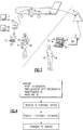
Figure 3 , theRFID tag 18 is illustrated with other elements of the system. Amaintenance technician 40 is shown carrying theportable device 62, such as a personal digital assistant, having both electronically readable and writable memory, processor, display and keyboard as well as a radio frequency receiver and transmitter. Theportable device 62 is used bymaintenance technician 40 to access and write part information on theRFID tag 18 by communicating with theRFID tag 18 through a radio frequency signal. In addition, theportable device 62 has programming that permits the formatting of information, such as part information, into anelectronic document 34. Theelectronic document 34 may be an XML format that permits posting of information on the internet. - In addition, the
maintenance technician 40 is shown wearing anidentification badge 38 with anRFID tag 54, which is constructed in the same manner as theRFID tag 18. TheRFID tag 54 stores information relating to the identification of themaintenance technician 40 as well as security verification information that permits themaintenance technician 40 access toportable device 62 as well asRFID tag 18. - An
aircraft 10 also includes anaircraft computer 58, which acts as a server for theportable device 62. Theportable device 62 communicates wirelessly with theaircraft computer 58 using radio frequency waves. Accordingly, theaircraft computer 58 is linked with a receiver and transmitter for communication with theportable device 62 as well as acell tower 70 or other relay device, such as a satellite. Thecell tower 70 is in communication with asecond server 64, which is a computer located at a remote location such as a maintenance organization or airline facility. Thesecond server 64 is linked with acomputer 72 having a display and keyboard. With proper authorization, aworker 74 has access to thecomputer 72. - With reference to
Figure 3 and 4 , the method for aircraft maintenance will now be explained. Amaintenance technician 40 removes or otherwise services theaircraft part 14. Using theportable device 62, themaintenance technician 40 prompts theRFID tag 18 to transmit part information to theportable device 62, which stores information in its memory. This part information is stored on theportable device 62 when theaircraft part 14 is either repaired or replaced. Themaintenance technician 40 inputs a notation of any change made to theaircraft part 14 into theportable device 62 by a keyboard 63. For example, if theaircraft part 14 is repaired, themaintenance technician 40 can input the type and nature of repair as well as the date of repair into memory of theportable device 62. This information can later be transmitted to a remote location. Theportable device 62 may have programming that walks themaintenance technician 40 through the repair of theaircraft part 14 step by step. - Alternatively, the change may be a replacement of the
aircraft part 14 by another aircraft part, such as areplacement part 46. Like theaircraft part 14, thereplacement part 46 has an RFID tag 50. The RFID tag 50 stores thereplacement part 46 information, which is the same type of information as found on theRFID tag 18, such as revision history of the part, part configuration, service history, part number, serial number or other related information. Through theportable device 62, themaintenance technician 40 prompts the RFID tag 50 of thereplacement part 46 to wirelessly transmit replacement part information to theportable device 62. Theportable device 62 then stores replacement part information in memory along with the previously stored part information relating to theaircraft part 14. Themaintenance technician 40 then uses the keyboard 63 on theportable device 62 to record that areplacement part 46 has replaced theprevious aircraft part 14. - The
maintenance technician 40 then prompts theportable device 62 to obtain information relating to the identity of themaintenance technician 40 from theRFID tag 54 and information relating to the identification of theaircraft 10. To facilitate obtaining information about theaircraft 10, theaircraft 10 may have anRFID tag 66, which records its identification number, such as its manufacturer's identification number or the identity of the aircraft in the fleet. Once this information is obtained, then theportable device 62 formats part information, replacement part information (if part is replaced), aircraft identification, maintenance technician identification and notes concerning the nature of service, such as a note that the part has been changed, into anelectronic document 34, which is formatted in XML. - The
portable device 62 transmitselectronic document 34 to a remote location, such as anaircraft computer 58, which then relays theelectronic document 34 to acell tower 70, which passes theelectronic document 34 to asecond server 64 through the internet. Thecomputer 72 then displays theelectronic document 34 to permit viewing by aworker 74, who is located at the remote facility. Theelectronic document 34 may be stored by asecond server 64 as well as theaircraft computer 58 and theportable device 62. - In addition, the
portable device 62 can further write information wirelessly onto theRFID tag 18 as well as the RFID tag 50. Amaintenance technician 40 can accordingly input into both or either RFID tags 18 and 50 information relating to the maintenance of these parts as well as other notes. In this way, a service history of the part can be maintained to facilitate the future use and/or repair of theaircraft 10. - The foregoing description shall be interpreted as illustrative and not in any limiting sense. A worker of ordinary skill in the art would recognize that certain modifications would come within the scope of this invention. For that reason, the follow claims should be studied to determine the true scope and content of this invention.
Claims (14)
- An aircraft part assembly comprising:an aircraft part (14);a metal data plate (20) mounted on said aircraft part (14); anda radio frequency identification tag (RFID tag) (18) coupled to said metal data plate (20) such that said metal data plate (20) is an RFID tag resonator.
- The aircraft part assembly of claim 1, wherein said RFID tag (18) is between said metal data plate (20) and said aircraft part (14).
- The aircraft part assembly of claim 1 or claim 2, wherein said RFID tag (18) comprises:a writeable memory unit (26) for storing part information;a processor (30) for processing part information;a wireless transmitter (22) in communication with the writeable memory unit (26); anda wireless receiver (22) in communication with the writable memory unit (26).
- The aircraft part assembly of claim 3, wherein said part information comprises at least one of a revision history, a service history, a part configuration, a part number, and a serial number.
- The aircraft part assembly of any preceding claim, wherein said RFID tag (18) is capacitively coupled to said metal data plate (20).
- The aircraft part assembly of any of claims 1 to 4, wherein said RFID tag (18) is inductively coupled to said metal data plate (20).
- The aircraft part assembly of any preceding claim, wherein said metal data plate (20) is mounted to said aircraft part (14) via a U-shaped bracket (80).
- The aircraft part assembly of claim 7, wherein said RFID tag (18) is mounted to a dielectric substrate (84) within a gap (82) defined by said U-shaped bracket (80).
- The aircraft part assembly of any preceding claim, wherein said RFID tag (18) is mounted to said metal data plate (20) via a dielectric layer (84).
- A method of conducting aircraft maintenance, comprising the steps of:receiving stored part information relating to an aircraft part (14) from a radio frequency identification (RFID) tag (18) coupled to a part data plate (20), such that said part data plate (20) is an RFID tag resonator, on said part using a portable device (62);receiving stored replacement part information relating to a replacement part (46) from an RFID tag (50) coupled to a replacement part data plate, such that said replacement part data plate is an RFID tag resonator, on said replacement part (46) using said portable device (62);formatting said part information and said replacement part information into an electronic document (34); andwirelessly transmitting the electronic document (34) to a server (58).
- The method of claim 10, wherein each of said part information and said replacement part information comprises at least one of a revision history, a service history, a part configuration, a part number, and a serial number.
- The method of claim 10 or claim 11, further comprising the step of transmitting new replacement part information from said portable device (62) to said replacement part RFID tag (50), thereby causing said replacement part information to be overwritten with said new replacement part information.
- The method of any of claims 10 to 12, wherein said server (58) is on an aircraft (10) containing said aircraft part.
- The method of claim 13, further comprising the step of relaying the electronic document (34) from said server (58) to a remote server (64), wherein said remote server (64) is away from said aircraft (10).
Applications Claiming Priority (1)
| Application Number | Priority Date | Filing Date | Title |
|---|---|---|---|
| US13/032,235 US20110140866A1 (en) | 2008-03-26 | 2011-02-22 | Wireless aircraft maintenance log |
Publications (2)
| Publication Number | Publication Date |
|---|---|
| EP2492849A2 true EP2492849A2 (en) | 2012-08-29 |
| EP2492849A3 EP2492849A3 (en) | 2014-09-03 |
Family
ID=45655253
Family Applications (1)
| Application Number | Title | Priority Date | Filing Date |
|---|---|---|---|
| EP12152729.5A Withdrawn EP2492849A3 (en) | 2011-02-22 | 2012-01-26 | Wireless aircraft maintenance log |
Country Status (1)
| Country | Link |
|---|---|
| EP (1) | EP2492849A3 (en) |
Cited By (4)
| Publication number | Priority date | Publication date | Assignee | Title |
|---|---|---|---|---|
| EP3193311A1 (en) * | 2016-01-14 | 2017-07-19 | Siemens Aktiengesellschaft | Rail vehicle component group and method for generating a life cycle of a machine component and service method for maintenance |
| GB2565147A (en) * | 2017-08-04 | 2019-02-06 | Carolfile Ltd | Intelligent vehicle parts |
| DE102019124009A1 (en) * | 2019-09-06 | 2021-03-11 | Airbus Operations Gmbh | Procedure for determining the interchangeability of structurally modified means of transport components |
| US20210171220A1 (en) * | 2019-12-06 | 2021-06-10 | The Boeing Company | Systems and methods for processor module failure assessment |
Family Cites Families (8)
| Publication number | Priority date | Publication date | Assignee | Title |
|---|---|---|---|---|
| CA2544736A1 (en) * | 2003-11-04 | 2005-05-19 | Avery Dennison Corporation | Rfid tag with enhanced readability |
| US20050159222A1 (en) * | 2003-12-18 | 2005-07-21 | Matthew Pasulka | Data plate |
| JP2005210676A (en) * | 2003-12-25 | 2005-08-04 | Hitachi Ltd | Wireless IC tag, wireless IC tag manufacturing method, and wireless IC tag manufacturing apparatus |
| EP1797543B1 (en) * | 2004-10-04 | 2010-12-15 | Emerson & Cuming Microwave Products | Improved rfid tags |
| US7688206B2 (en) * | 2004-11-22 | 2010-03-30 | Alien Technology Corporation | Radio frequency identification (RFID) tag for an item having a conductive layer included or attached |
| US7315248B2 (en) * | 2005-05-13 | 2008-01-01 | 3M Innovative Properties Company | Radio frequency identification tags for use on metal or other conductive objects |
| US7551086B2 (en) * | 2005-09-20 | 2009-06-23 | The Boeing Company | System and methods for tracking aircraft components |
| WO2008079902A1 (en) * | 2006-12-21 | 2008-07-03 | Neology, Inc. | Systems and methods for a rfid enabled metal license plate |
-
2012
- 2012-01-26 EP EP12152729.5A patent/EP2492849A3/en not_active Withdrawn
Non-Patent Citations (1)
| Title |
|---|
| None |
Cited By (8)
| Publication number | Priority date | Publication date | Assignee | Title |
|---|---|---|---|---|
| EP3193311A1 (en) * | 2016-01-14 | 2017-07-19 | Siemens Aktiengesellschaft | Rail vehicle component group and method for generating a life cycle of a machine component and service method for maintenance |
| WO2017121577A1 (en) * | 2016-01-14 | 2017-07-20 | Siemens Aktiengesellschaft | Railway vehicle component group and method for generating a life history of a machine component and service method for maintenance |
| RU2682371C1 (en) * | 2016-01-14 | 2019-03-19 | Сименс Акциенгезелльшафт | Group of the rail vehicle units and the machine component life cycle generation method, and the maintenance method for the maintenance service |
| US10654502B2 (en) | 2016-01-14 | 2020-05-19 | Siemens Mobility GmbH | Rail vehicle component group and method for generating a life history of a machine component and service method for maintenance |
| GB2565147A (en) * | 2017-08-04 | 2019-02-06 | Carolfile Ltd | Intelligent vehicle parts |
| DE102019124009A1 (en) * | 2019-09-06 | 2021-03-11 | Airbus Operations Gmbh | Procedure for determining the interchangeability of structurally modified means of transport components |
| US20210171220A1 (en) * | 2019-12-06 | 2021-06-10 | The Boeing Company | Systems and methods for processor module failure assessment |
| US11661211B2 (en) * | 2019-12-06 | 2023-05-30 | The Boeing Company | Systems and methods for processor module failure assessment |
Also Published As
| Publication number | Publication date |
|---|---|
| EP2492849A3 (en) | 2014-09-03 |
Similar Documents
| Publication | Publication Date | Title |
|---|---|---|
| US20090243854A1 (en) | Wireless aircraft maintenance log | |
| US7080778B1 (en) | Moveable object accountability system | |
| US10275952B2 (en) | System for automated recording of aircraft flight and maintenance information and associated methods | |
| US20110060600A1 (en) | Systems and Methods For Tracking the Transportation of Passengers | |
| US10373402B2 (en) | Commercial driver electronic logging rule compliance and vehicle inspection voice assistant system | |
| US20080133432A1 (en) | Automated rental vehicle check-in system | |
| US20050242181A1 (en) | Method for associating an asset with a monitoring device | |
| CA2693011C (en) | Information transmission and processing systems and methods for freight carriers | |
| US9877296B2 (en) | Electronic tag with cellular communication module | |
| US9836103B2 (en) | Wireless personal tracking device | |
| US20090234517A1 (en) | Automatic configuration-tracking apparatus, and a method and a system for such tracking | |
| EP3485759A1 (en) | Electronic baggage tag | |
| EP2492849A2 (en) | Wireless aircraft maintenance log | |
| US20080217409A1 (en) | RFID tag communicating apparatus | |
| US9947147B1 (en) | Vehicle electronic logging authorization and handover system | |
| EP3779818A1 (en) | Systems and methods for verifying a location of an item | |
| GB2561534A (en) | Item tracking | |
| US10347055B2 (en) | Method and apparatus for connecting to a heavy duty vehicle and performing a vehicle roadworthiness check | |
| EP3812968B1 (en) | Intelligent fasteners | |
| CN104420766A (en) | Device for monitoring cash boxes on bank vault escort vehicle in real time all the way | |
| US20110140866A1 (en) | Wireless aircraft maintenance log | |
| US20050096939A1 (en) | Automated rental vehicle check-in system | |
| KR101102922B1 (en) | Method and system for providing vehicle / user location information using identification code | |
| EP3087536B1 (en) | Electronic tag with cellular communication module | |
| EP3393886B1 (en) | System and method for providing information to an information system in a vehicle |
Legal Events
| Date | Code | Title | Description |
|---|---|---|---|
| PUAI | Public reference made under article 153(3) epc to a published international application that has entered the european phase |
Free format text: ORIGINAL CODE: 0009012 |
|
| AK | Designated contracting states |
Kind code of ref document: A2 Designated state(s): AL AT BE BG CH CY CZ DE DK EE ES FI FR GB GR HR HU IE IS IT LI LT LU LV MC MK MT NL NO PL PT RO RS SE SI SK SM TR |
|
| AX | Request for extension of the european patent |
Extension state: BA ME |
|
| PUAL | Search report despatched |
Free format text: ORIGINAL CODE: 0009013 |
|
| AK | Designated contracting states |
Kind code of ref document: A3 Designated state(s): AL AT BE BG CH CY CZ DE DK EE ES FI FR GB GR HR HU IE IS IT LI LT LU LV MC MK MT NL NO PL PT RO RS SE SI SK SM TR |
|
| AX | Request for extension of the european patent |
Extension state: BA ME |
|
| RIC1 | Information provided on ipc code assigned before grant |
Ipc: G06K 19/077 20060101AFI20140731BHEP Ipc: G07C 5/08 20060101ALI20140731BHEP Ipc: G06Q 10/08 20120101ALI20140731BHEP Ipc: G06Q 10/00 20120101ALI20140731BHEP |
|
| 17P | Request for examination filed |
Effective date: 20150303 |
|
| RBV | Designated contracting states (corrected) |
Designated state(s): AL AT BE BG CH CY CZ DE DK EE ES FI FR GB GR HR HU IE IS IT LI LT LU LV MC MK MT NL NO PL PT RO RS SE SI SK SM TR |
|
| 17Q | First examination report despatched |
Effective date: 20150709 |
|
| RAP1 | Party data changed (applicant data changed or rights of an application transferred) |
Owner name: UNITED TECHNOLOGIES CORPORATION |
|
| STAA | Information on the status of an ep patent application or granted ep patent |
Free format text: STATUS: THE APPLICATION IS DEEMED TO BE WITHDRAWN |
|
| 18D | Application deemed to be withdrawn |
Effective date: 20160802 |