EP2492668A1 - System and method for monitoring painting quality of components, in particular of motor-vehicle bodies - Google Patents
System and method for monitoring painting quality of components, in particular of motor-vehicle bodies Download PDFInfo
- Publication number
- EP2492668A1 EP2492668A1 EP11156248A EP11156248A EP2492668A1 EP 2492668 A1 EP2492668 A1 EP 2492668A1 EP 11156248 A EP11156248 A EP 11156248A EP 11156248 A EP11156248 A EP 11156248A EP 2492668 A1 EP2492668 A1 EP 2492668A1
- Authority
- EP
- European Patent Office
- Prior art keywords
- light
- camera
- source
- monitored
- defects
- Prior art date
- Legal status (The legal status is an assumption and is not a legal conclusion. Google has not performed a legal analysis and makes no representation as to the accuracy of the status listed.)
- Granted
Links
Images



Classifications
-
- G—PHYSICS
- G01—MEASURING; TESTING
- G01N—INVESTIGATING OR ANALYSING MATERIALS BY DETERMINING THEIR CHEMICAL OR PHYSICAL PROPERTIES
- G01N21/00—Investigating or analysing materials by the use of optical means, i.e. using sub-millimetre waves, infrared, visible or ultraviolet light
- G01N21/84—Systems specially adapted for particular applications
- G01N21/88—Investigating the presence of flaws or contamination
- G01N21/95—Investigating the presence of flaws or contamination characterised by the material or shape of the object to be examined
- G01N21/9515—Objects of complex shape, e.g. examined with use of a surface follower device
-
- G—PHYSICS
- G01—MEASURING; TESTING
- G01N—INVESTIGATING OR ANALYSING MATERIALS BY DETERMINING THEIR CHEMICAL OR PHYSICAL PROPERTIES
- G01N21/00—Investigating or analysing materials by the use of optical means, i.e. using sub-millimetre waves, infrared, visible or ultraviolet light
- G01N21/84—Systems specially adapted for particular applications
- G01N21/88—Investigating the presence of flaws or contamination
- G01N21/95—Investigating the presence of flaws or contamination characterised by the material or shape of the object to be examined
- G01N21/9515—Objects of complex shape, e.g. examined with use of a surface follower device
- G01N2021/9518—Objects of complex shape, e.g. examined with use of a surface follower device using a surface follower, e.g. robot
Definitions
- the present invention refers to a system for monitoring painting quality of components, for example of motor-vehicle bodies, of the type comprising at least one source of light for illuminating the components, at least one camera for inspecting the illuminated components and electronic means for processing the signals coming from the camera.
- a system of this type is for example described in document JP-A-7012750 .
- the object of the present invention is that of providing a monitoring system of the type described above capable of searching all the abovementioned types of defects and if necessary and desired also marking thereof and capable of being used along a production line without varying the cycle time of the line.
- a further object of the invention is that of providing a system of the previously indicated type capable of precisely and accurately detecting the painting quality and in an extremely rapid manner.
- a further object of the invention is that of providing a system of the previously indicated type that is relatively simple, inexpensive and reliable.
- the invention aims at providing a system for monitoring painting quality of components, for example of motor-vehicle bodies, having the characteristics indicated at the beginning of the present description and characterised in that said system further comprises:
- the source of light comprises an aligned series of white light LED sources, and an opaque shield arranged opposite said series of sources and having a rectilinear fissure parallel to said aligned series of LED sources.
- the components to be monitored are carried in succession along a conveying line and said robot is arranged stationary beside the line and it is controlled so as to impart to said monitoring head a basic speed to follow the movement of the components along the line and an additional speed considerably greater than the basic speed, to obtain the monitoring movement with respect to the monitored component.
- the abovementioned angle of incidence is equivalent to about 30°
- the distance of the source of light from the monitored surface, measured along the illumination direction is comprised between 150mm and 200mm
- the distance between the lens of the camera and the monitored surface, measured along the optical axis of the camera is comprised between 350mm and 650mm.
- such distances were respectively equivalent to 175mm and 472mm.
- the monitoring head carried by said robot also includes a marking device, for marking an area of the monitored surface where a defect has been detected.
- marking device is an inkjet device.
- the device according to the invention is capable of precisely and rapidly monitoring the painting quality, hence allowing not extending the cycle time of the production line when the device is used along the line.
- the electronic means which process the signals coming from the camera are programmed for acquiring the images acquired by the camera with a predefined frame rate, for extracting light profiles corresponding to said images, for providing such data for the analysis and thus for performing three processing cycles, in sequence or in parallel with respect to each other, based on three different algorithms, for detecting small defects, medium defects and large defects as well as drippings on the edges.
- the invention also has the object of providing the method implemented through the system according to the invention.
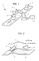
- a production line (illustrated solely schematically in the diagram) along which components 2 previously subjected to painting move is indicated in its entirety with reference 1 in figure 1 .
- the components 2 are illustrated as generic components in the drawing. However, the concrete embodiment described herein specifically refers to the case of motor-vehicle bodies coming from a painting station where they were subjected to painting.
- the system according to the invention for monitoring the painting quality of the components 2 is indicated in its entirety with reference number 3.
- the system 3 comprises a manipulator robot 4, of any known type, prearranged at stationary position (obviously, in the case of the specific illustrated example it can be instead provided for that the base of the be mobile along the line) and carrying a monitoring head 5 adapted to provide - in output - electrical signals that are processed by an electronic processing unit 6.
- the monitoring head 5 comprises a support structure carrying, in a relatively fixed position with respect to each other, a source of light 7 and a camera 8.
- the source of light 7 comprises a support plate 8 carrying an aligned series of white light LED sources 9, opposite to which an opaque shield 10 having a rectilinear fissure 11 parallel and facing the aligned series of LED sources 9 is arranged.
- the source of light 7 is adapted to emit - coming from the fissure 11 - a flat blade of light L in the direction of the surface S to be monitored.
- the system for controlling the robot 4 provides for moving the monitoring head 5 at a speed which is the sum of a basic speed corresponding to the speed V of advancement of line 1, which allows the monitoring head 5 to follow the component 2 to be monitored along the travel thereof in the line 1, plus an additional speed, much greater than the basic speed which allows moving the monitoring head 5 (including the source of light 7 and the camera 8) with respect to the surface to be monitored S ( figure 2 ) so as to perform the monitoring operations.
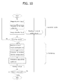
- Figure 2 schematically shows the trajectory T of the movement of the monitoring head 5 (carrying both the source of light 7 and the camera 8) with respect to the surface S of the component to be monitored.
- the monitoring head moves with respect to the surface S in a main direction indicated by the arrow A in figure 2 , but during such movement, such head also moves in the direction perpendicular to the surface S so as to maintain the distance of the source 7 and of the camera 8 from such surface constant.
- the profile of the trajectory T precisely corresponds to the profile of the surface to be monitored S in a section parallel to the main direction of movement A.
- the blade of light L impacts the surface to be monitored S along a line z ( figure 2 ) and it is thus reflected in the direction of the camera 8.
- the main direction of movement A is perpendicular to the abovementioned line z of intersection between the blade of light L emitted by the source of light 7 and the surface S to be monitored.
- the source of light 7 and the camera 8 are arranged and oriented as better observable in figure 6 .
- the blade of light L emitted by the source 7 forms - with a plane n normal to the surface S along the line of incidence z - an angle ⁇ which is preferably comprised between 20° and 40°.
- the camera 8 has the optical axis thereof which impacts the surface S in a point of the line z of incidence of the blade of light L on the surface S.
- the angle formed between the optical axis of the camera 8 with respect to the normal plane n is also equivalent to ⁇ , so that the camera 8 is capable of acquiring the light emitted by the source 7 and reflected by the surface S. Therefore, in the case of the aforementioned concrete embodiment, even such angle was equivalent to 30°.
- Figure 6 also shows the distances defining the positioning of the source 7 of the camera 8 in the abovementioned concrete embodiment.
- the distance between the source of light 7 and the monitored surface S, measured along the illumination direction is comprised between 150mm and 200mm (in the concrete embodiment it was equivalent to 175mm) and if the distance between the lens of the camera 8 and the monitored surface S, measured along the optical axis of the camera is comprised between 350mm and 650mm (in the concrete embodiment it was equivalent to 472mm).
- Figure 7 schematically shows a variant of figure 2 , in which a marking device 12, for example constituted by an inkjet head, adapted to mark with an ink spot 13 areas of the surface S where the system according to the invention has detected a painting defect 14, in the manner to be described hereinafter, is mounted adjacent to the source of light 7.
- the liquid jet head 12 is activated by the control system (by supplying air and pressurised liquid) to generate an atomised liquid spray which settles on the surface of the component in proximity of a detected defect.
- the control system by supplying air and pressurised liquid
- the control system by supplying air and pressurised liquid to generate an atomised liquid spray which settles on the surface of the component in proximity of a detected defect.
- algorithms capable of detecting the defects with extremely low calculation times. For example, considering a movement of the robot equivalent to 20m/min and a calculation time of 100ms, the positioning error of the marking is of about 33.3mm.
- the electronic processing unit 6 receives signals from the camera 8 corresponding to the images acquired thereby, according to a predefined frame rate.
- a low time of exposure for example 1800 ⁇ s
- a high frame rate for example 500 images/second
- a resolution of each acquisition in the order of 0.67mm can be obtained.
- Figure 8 shows - by way of illustration - an example of an image IA acquired by the camera 8 and an example of a diagram PE of the profile of light intensity obtained as a pre-processing of the image IA.
- the system according to the invention is capable of performing all the control algorithms in parallel or in sequence, reaching to the final decision of marking the examined area as having a defect or defect-free.
- such algorithms comprise:
- Figure 11 indicates the structures of the three algorithms that allow detecting three different categories of defects.
- the system receives - in input - a flow of profiles extracted by the camera as indicated in Figure 8 .
- the system processes each image coming from the camera and examines the position of the reflection for each column of the image.
- the centre of the reflection is calculated as coordinate y obtaining the profile P(x) relative to the image I - in input - with x varying from 1 to M.
- the system composes a vector B in the N outputs O(x) obtained by analysing N images in entry. Therefore, the system processes intensity blocks B(x, y) with x ranging between 1 to M and y ranging from 1 to N.
- the blocks can be superimposed and the system is capable of operating with blocks of variable dimensions, from a minimum of 2 components up to a theoretical maximum equivalent to all available N images of the camera.
- the possibility of block operations allows regulating the operation of the system in real time and the delay in the actuation for signalling the defects.
- the algorithm for detecting small defects is conducted in two main steps:
- the intensities contained in the matrix B(x,y) may vary within a predefined range which depends on the "bit per pixel" parameter of the camera. Without reducing details, reference hereinafter shall be made to 8 bits per pixel and thus a variability range comprised between 0 and 255.
- Areas of potential defect are identified creating the binary matrix D 1 having the same dimensions as B(x, y) which has value 1 only in points (x, y) where 12(x, y) is greater than the threshold S1 (which for example may have the value of 5) and zero value for all the other points.
- the binary matrix D2 is created having the same dimensions as B(x, y) which has value 1 only in the points (x, y) where the matrix B(x, y) is greater than the threshold S2 (which for example may have the value of 30) and value zero for all the other points.
- a morphological analysis is carried out on the obtained matrix D3(x, y) which searches the 1 regions of the matrix with 8-pixel connectivity and the element with greater area is selected. Then, a matrix D4(x, y) is created having the same dimensions as B(x, y) which has value 1 only at the points (x, y) that correspond to the points belonging to the element having a greater area identified in the previous step and value zero for all the other points.
- a morphological analysis is carried out on the matrix D4(x, y) in which an operation for filling the zero bits within the element present in the matrix D4(x, y) is carried out, i.e. the zero pixels within the element are identified and switched one by one.
- the matrix thus obtained is named D5(x, y) and by definition, if containing at least one element, it shall be compact in the sense that there will be no zero pixels therein.
- a morphological analysis is carried out on the matrix D5(x, y) in which an operation for eroding the element present in the matrix D5(x, y) is carried out, i.e. the pixels on the edge of the element contained therein are identified and eroded using a structuring element, for example a 10-pixel disc.
- the matrix thus obtained is named D6(x, y). In this manner, if the matrix D6(x, y) contains one element, it shall be compact in that there will be no zero-pixels therein.
- the binary matrix D8(x,y) is created having the same dimensions as B(x, y) which has value 1 only at the points (x, y) where the matrix D7(x, y) assumes the value 1 and it is simultaneously verified whether the point (x, y) is far at least by Q pixels from the edge of the matrix and zero for all the other points.
- S3 i.e. the maximum area of the small defects
- S4 i.e. the minimum area for the small defects (which for example can be placed at the value 120 for S3 and 1 for S4).
- a morphological analysis is carried out on the obtained matrix D8(x, y) which identifies all the elements present connected with 8-pixel connectivity and the following cycle is carried out for all elements found in the matrix D8(x, y):
- the second value of grey shade present in the matrix Particular(x, y) from a scale obtained by ordering the grey shades present in the matrix Particular(x, y) in an increasing order is associated to the pixels contained in the matrix Particular(x, y) which have the value equivalent to zero.
- variable S8 whose value will be equivalent to the segmentation threshold calculated by means of the Otsu method ( Otsu, N., "A Threshold Selection Method from Gray-Level Histograms," IEEE Transactions on Systems, Man, and Cybernetics, Vol. 9, No. 1, 1979, pp. 62-66 ) is created.
- Otsu N., "A Threshold Selection Method from Gray-Level Histograms," IEEE Transactions on Systems, Man, and Cybernetics, Vol. 9, No. 1, 1979, pp. 62-66 .
- Such method selects by means of iteration the threshold which minimises the interclass variance between the population of the 0 and 1 pixels in the binarized image with the current threshold).
- the matrix D9(x, y) is created having the same dimensions as the matrix Particular(x, y) which has the pixels (x, y) thereof at 1 when the corresponding pixel in the matrix Particular(x, y) is smaller than the threshold S8.
- the Boolean variable C3 is created and it will assume the value 1 if the sum of the 1-pixels of the matrix D9(x, y) is smaller than the threshold S3 (i.e. the maximum area of the small defect), and a zero in the other case.
- the Boolean variable C4 is created and it shall assume the value equivalent to the result of the AND logic between the variables C1 and C3.
- the parameter S9 is created indicating the dimension - in pixels - of the frame around the edge of the matrix Particular(x, y) which shall be used in the following control (for example initialized at the value 2).
- the variable C5 which will assume the value 1 when the sum of the pixels in the matrix D9(x, y) arranged within the frame S9 pixels wide from the edge of the matrix D9(x, y) is smaller than the threshold S10 (which for example is initialized at the value 10), is created.
- the threshold S11 equivalent to a number between 0 and 1 (for example equivalent to the 2/3 ratio) is created and it is used for calculating the threshold S12 equivalent to the integer closest to the product between the semi-length dimension of the matrix Particular(x, y) and the threshold S 11.
- variable C6 which assumes the value 1 if the standard diversion of the pixels in the matrix Particular(x, y) arranged within the frame S12 pixels wide from the edge of the matrix Particular(x, y) is smaller than the threshold S13 (which for example is initialized at the value 10), and zero in the other case, is created.
- the defect may be classified with different gravity (for example for areas smaller than 5 pixels the defect is classified as negligible, for areas comprised between 10 and 5 pixels the defect is classified as negligible in some areas of the surface and grave in others, for areas larger than 10 pixels the defect is always grave in any region of the surface).
- the following algorithm identifies medium defects (for example defects of the orange peel type).
- the matrix I4(x, y) is created having the same dimensions as B(x, y) which assumes the same values of the matrix I3(x, y) only in the sub-blocks (for example measuring 32 ⁇ 32 pixels) for which it has a mean greater than zero, and it is zero in all the other blocks.
- the pixels of the block equivalent to the mean value of the corresponding block in the matrix I3(x, y) will be placed within each block in I4(x, y).
- a binary matrix 15(x, y) having value 1 for the pixel for which the matrix I4(x, y) has values between the threshold S14 and S15 (which for example may have the value of 0.3 and 0.8, respectively) is created.
- the matrix I6(x, y) is created divided into sub-blocks (for example measuring 32 x 32 pixels) where - within each block in I6(x, y) - the pixels of the block equivalent to the mean value of the corresponding block in the matrix I5(x, y) will be placed.
- the matrix I7(x, y) is created as the sub-sampling of the matrix I6(x, y) where each pixel of the matrix I7(x, y) is equivalent to the mean value of the corresponding block of the matrix I6(x, y).
- a morphological filtering is carried out on the erosion matrix I7(x, y), for example with a structuring element equivalent to a 1-pixel radius disk producing the matrix I8(x, y)
- a morphological analysis is carried out on the obtained matrix I8(x, y) which identifies all the elements present connected with 8 pixels connectivity and the following cycle is carried out for all the elements found in the matrix I8(x, y).
- a matrix I9(x, y) is created having the same dimensions as I8(x, y) initialized at 0. The area is considered for each element and only the elements connected with area greater than the threshold S16 (which for example may have the value of 3 pixels) will be considered and indicated in the matrix I9(x, y) in the corresponding position as medium defects (for example as defects of the orange peel type)
- the matrix I9(x, y) is supersampled by the reverse desampling ratio which was used to produce the matrix I7(x, y) so that the final dimension of I9(x, y) is equivalent to that of the block B(x, y).
- the matrix I9(x, y) thus calculated hence indicates the medium defects map (for example as defects of the orange peel type)
- the detection of defects on the edge is obtained by scanning the edges (for example by imparting a scanning path capable of keeping the blade of light orthogonal to the edge to be analysed) and by analysing the matrix B(x,y) as follows.
- Filtering is carried out on the matrix D2(x, y) for the detection of the edges of the objects, for example according to the Prewitt method (i.e. the method which finds the edges using the Prewitt approximation to the derivative and where the edges whose points have maximum gradient of the entering image are arranged exiting) obtaining the matrix D10(x, y) having the same dimensions as D2(x, y)
- the Prewitt method i.e. the method which finds the edges using the Prewitt approximation to the derivative and where the edges whose points have maximum gradient of the entering image are arranged exiting
- the matrix D10(x, y) is scanned by columns and the first 1-pixel along the column in D10(x, y) is skipped in the vector Edges(x) obtaining a vector which estimates the position of the surface edge under scrutiny.
- the following detection is not carried out.
- the vector Retta(x) being the vector containing for each column the value along the axis y of the interpolating line.
- a matrix D11(x, y) initialised to zero and which assumes the value 1 only in the pixels (x, y) where the following inequality Retta(x) ⁇ y ⁇ Edges(x) is true for all the columns along the axis x is created.
- the matrix D11(x, y) represents a set of candidates of defects on the edges, for example the drippings.
- a morphological analysis is carried out on the obtained matrix D11(x, y) which identifies all the elements present connected with 8-pixel connectivity and the following cycle is carried out for all the elements found in the matrix D11(x, y). Only the elements with an area comprised between the thresholds S 17 and S18 (for example equivalent to 40 and 800 pixels respectively) are considered as defects along the edges, for example the drippings.
- the system and the method according to the invention enable detecting and possibly also marking painting defects in components moving along a production line, in a precise and quick manner, without extending the cycle time of the line, and through relatively simple and inexpensive means.
Landscapes
- Physics & Mathematics (AREA)
- Health & Medical Sciences (AREA)
- Life Sciences & Earth Sciences (AREA)
- Chemical & Material Sciences (AREA)
- Analytical Chemistry (AREA)
- Biochemistry (AREA)
- General Health & Medical Sciences (AREA)
- General Physics & Mathematics (AREA)
- Immunology (AREA)
- Pathology (AREA)
- Investigating Materials By The Use Of Optical Means Adapted For Particular Applications (AREA)
Abstract
Description
- The present invention refers to a system for monitoring painting quality of components, for example of motor-vehicle bodies, of the type comprising at least one source of light for illuminating the components, at least one camera for inspecting the illuminated components and electronic means for processing the signals coming from the camera. A system of this type is for example described in document
JP-A-7012750 - In the specific case of monitoring painting quality of motor-vehicle bodies, there still arises the need of detecting various types of vehicle body painting defects, substantially classifiable in three different categories: small defects, such as for example small spots (see
figure 9A of the attached drawings), medium defects, such as for example "orange peel" effects, (seefigure 9B ) and large defects, such as for example paint dripping on the edges of the vehicle body (seefigure 9C ). Regardless of the dimensions thereof, the defects may also be of various types: scratches, linings, peeling, alteration or absence of colour etc. - The object of the present invention is that of providing a monitoring system of the type described above capable of searching all the abovementioned types of defects and if necessary and desired also marking thereof and capable of being used along a production line without varying the cycle time of the line.
- A further object of the invention is that of providing a system of the previously indicated type capable of precisely and accurately detecting the painting quality and in an extremely rapid manner.
- A further object of the invention is that of providing a system of the previously indicated type that is relatively simple, inexpensive and reliable.
- With the aim of attaining such objects, the invention aims at providing a system for monitoring painting quality of components, for example of motor-vehicle bodies, having the characteristics indicated at the beginning of the present description and characterised in that said system further comprises:
- a manipulator robot, carrying a monitoring head including both the abovementioned source of light and the abovementioned camera, with said source of light and said camera maintained in a fixed position with respect to each other, said robot being adapted to move the source of light and the camera with respect to the monitored component in a main direction of movement and according to a trajectory parallel to a surface of the component, maintaining the source of light and the camera each at a constant distance from such surface of the component, so that such movement trajectory follows a profile corresponding to the profile of said surface of the component,
said system further being characterised in that:- said source of light is adapted to emit a flat blade of light which impacts the monitored surface according to an illumination line perpendicular to said main direction of movement, the plane of said blade of light forming an angle of incidence with respect to the plane passing through said illumination line and perpendicular to the surface which is comprised between 20° and 40°,
- said camera being positioned and oriented with respect to said source of light so that the optical axis of the camera impacts the monitored surface in a point of said illumination line and forms an angle with respect to the normal in said point on the monitored surface which is substantially equivalent to the abovementioned angle of incidence, so that said camera is capable of acquiring - by reflection - the image of the profile of the monitored surface along the intersection thereof with the blade of light emitted by said source of light.
- In the preferred embodiments, the source of light comprises an aligned series of white light LED sources, and an opaque shield arranged opposite said series of sources and having a rectilinear fissure parallel to said aligned series of LED sources.
- Still in the case of the abovementioned preferred embodiments, the components to be monitored are carried in succession along a conveying line and said robot is arranged stationary beside the line and it is controlled so as to impart to said monitoring head a basic speed to follow the movement of the components along the line and an additional speed considerably greater than the basic speed, to obtain the monitoring movement with respect to the monitored component.
- Still in the case of the abovementioned preferred embodiments, the abovementioned angle of incidence is equivalent to about 30°, the distance of the source of light from the monitored surface, measured along the illumination direction, is comprised between 150mm and 200mm and the distance between the lens of the camera and the monitored surface, measured along the optical axis of the camera, is comprised between 350mm and 650mm. In a concrete embodiment such distances were respectively equivalent to 175mm and 472mm.
- According to a further preferred characteristic, the monitoring head carried by said robot also includes a marking device, for marking an area of the monitored surface where a defect has been detected. Still according to preferred embodiments, such marking device is an inkjet device.
- Due to the abovementioned characteristics, the device according to the invention is capable of precisely and rapidly monitoring the painting quality, hence allowing not extending the cycle time of the production line when the device is used along the line.
- According to a further preferred characteristic, the electronic means which process the signals coming from the camera are programmed for acquiring the images acquired by the camera with a predefined frame rate, for extracting light profiles corresponding to said images, for providing such data for the analysis and thus for performing three processing cycles, in sequence or in parallel with respect to each other, based on three different algorithms, for detecting small defects, medium defects and large defects as well as drippings on the edges.
- The invention also has the object of providing the method implemented through the system according to the invention.
- Further characteristics and advantages of the invention shall be apparent from the description that follows with reference to the attached drawings, provided purely by way of non-limiting example, wherein:
-
figure 1 is a schematic perspective view of a monitoring system according to the invention, arranged beside a production line along which the components to be examined move, -
figure 2 is schematic view of the essential elements part of the monitoring head, also illustrating the movement trajectory of the monitoring head with respect to the monitored surface, -
figure 3 is a schematic perspective view of the source of light used in the system according to the invention, -
figure 4 is a front view of a part of the structure of the source of light, -
figure 5 is a further lateral schematic view of the source of light illustrated infigure 3 , -
figure 6 shows the positioning geometry of the essential elements of the monitoring head, -
figure 7 is a variant offigure 2 schematically illustrating an embodiment which is also provided with a head for marking the detected defect, -
figure 8 is a schematic view illustrating the operating principle of the system according to the invention, -
figures 9A , B, C are exemplifying representations of various types of painting defects of a motor-vehicle body, -
figure 10 is a block diagram illustrating the processing method implemented in the system according to the invention, and -
figure 11 illustrates further three block diagrams - in a summarised manner - showing the algorithms used for detecting small defects (left diagram), medium defects (central diagram) and large defects (right diagram). - A production line (illustrated solely schematically in the diagram) along which
components 2 previously subjected to painting move is indicated in its entirety with reference 1 infigure 1 . Thecomponents 2 are illustrated as generic components in the drawing. However, the concrete embodiment described herein specifically refers to the case of motor-vehicle bodies coming from a painting station where they were subjected to painting. The system according to the invention for monitoring the painting quality of thecomponents 2 is indicated in its entirety withreference number 3. Thesystem 3 comprises a manipulator robot 4, of any known type, prearranged at stationary position (obviously, in the case of the specific illustrated example it can be instead provided for that the base of the be mobile along the line) and carrying amonitoring head 5 adapted to provide - in output - electrical signals that are processed by an electronic processing unit 6. - With reference to the
figures 2-6 , themonitoring head 5 comprises a support structure carrying, in a relatively fixed position with respect to each other, a source of light 7 and acamera 8. As illustrated, specifically infigures 3-5 , the source of light 7 comprises asupport plate 8 carrying an aligned series of white light LED sources 9, opposite to which anopaque shield 10 having arectilinear fissure 11 parallel and facing the aligned series of LED sources 9 is arranged. - In the case of a concrete embodiment, 32 white light LED sources, with high luminosity (600mcd) arranged according to a pitch p equivalent to 14mm were used, the total length 1 of the
support 8 being equivalent to 500mm. Still in the case of such concrete embodiment, the distance d between the series of LEDs 9 and theshield 10 was equivalent to 5mm and the width w of thefissure 11 was equivalent to 1mm. - Due to the abovementioned configuration and arrangement, the source of light 7 is adapted to emit - coming from the fissure 11 - a flat blade of light L in the direction of the surface S to be monitored.
- In the case of the illustrated embodiment, the system for controlling the robot 4 provides for moving the
monitoring head 5 at a speed which is the sum of a basic speed corresponding to the speed V of advancement of line 1, which allows themonitoring head 5 to follow thecomponent 2 to be monitored along the travel thereof in the line 1, plus an additional speed, much greater than the basic speed which allows moving the monitoring head 5 (including the source of light 7 and the camera 8) with respect to the surface to be monitored S (figure 2 ) so as to perform the monitoring operations. -
Figure 2 schematically shows the trajectory T of the movement of the monitoring head 5 (carrying both the source of light 7 and the camera 8) with respect to the surface S of the component to be monitored. As observable, the monitoring head moves with respect to the surface S in a main direction indicated by the arrow A infigure 2 , but during such movement, such head also moves in the direction perpendicular to the surface S so as to maintain the distance of the source 7 and of thecamera 8 from such surface constant. Hence, the profile of the trajectory T precisely corresponds to the profile of the surface to be monitored S in a section parallel to the main direction of movement A. - The blade of light L impacts the surface to be monitored S along a line z (
figure 2 ) and it is thus reflected in the direction of thecamera 8. As clearly observable infigure 2 , the main direction of movement A is perpendicular to the abovementioned line z of intersection between the blade of light L emitted by the source of light 7 and the surface S to be monitored. - In order to allow the
camera 8 to acquire the light emitted by the source of light 7 and reflected by the surface S, the source of light 7 and thecamera 8 are arranged and oriented as better observable infigure 6 . As indicated in such figure, the blade of light L emitted by the source 7 forms - with a plane n normal to the surface S along the line of incidence z - an angle α which is preferably comprised between 20° and 40°. Studies and experiments conducted by the applicant revealed that a value of 30° for such angle is optimal. Thecamera 8 has the optical axis thereof which impacts the surface S in a point of the line z of incidence of the blade of light L on the surface S. The angle formed between the optical axis of thecamera 8 with respect to the normal plane n is also equivalent to α, so that thecamera 8 is capable of acquiring the light emitted by the source 7 and reflected by the surface S. Therefore, in the case of the aforementioned concrete embodiment, even such angle was equivalent to 30°.Figure 6 also shows the distances defining the positioning of the source 7 of thecamera 8 in the abovementioned concrete embodiment. Studies and experiments conducted by the Applicant revealed that it is advantageous if the distance between the source of light 7 and the monitored surface S, measured along the illumination direction, is comprised between 150mm and 200mm (in the concrete embodiment it was equivalent to 175mm) and if the distance between the lens of thecamera 8 and the monitored surface S, measured along the optical axis of the camera is comprised between 350mm and 650mm (in the concrete embodiment it was equivalent to 472mm). -
Figure 7 schematically shows a variant offigure 2 , in which amarking device 12, for example constituted by an inkjet head, adapted to mark with anink spot 13 areas of the surface S where the system according to the invention has detected apainting defect 14, in the manner to be described hereinafter, is mounted adjacent to the source of light 7. Theliquid jet head 12 is activated by the control system (by supplying air and pressurised liquid) to generate an atomised liquid spray which settles on the surface of the component in proximity of a detected defect. In order to reduce the distance between theactual defect 14 and markingliquid spot 13 to the minimum there are prearranged algorithms capable of detecting the defects with extremely low calculation times. For example, considering a movement of the robot equivalent to 20m/min and a calculation time of 100ms, the positioning error of the marking is of about 33.3mm. - During the movement of the
monitoring head 5 with respect to the surface to be monitored S, the electronic processing unit 6 receives signals from thecamera 8 corresponding to the images acquired thereby, according to a predefined frame rate. In order to allow rapid movements of the optical system, a low time of exposure (for example 1800µs) and a high frame rate (for example 500 images/second) with a movement of the monitoring head equivalent to 20m/minute, obtained through the robot 4 should be used. In such condition, a resolution of each acquisition in the order of 0.67mm can be obtained. -
Figure 8 shows - by way of illustration - an example of an image IA acquired by thecamera 8 and an example of a diagram PE of the profile of light intensity obtained as a pre-processing of the image IA. - As previously mentioned, the system according to the invention is capable of performing all the control algorithms in parallel or in sequence, reaching to the final decision of marking the examined area as having a defect or defect-free. With reference to
figure 8 , such algorithms comprise: - an acquisition cycle capable of detecting the images (for example with a frame rate of five hundred images per second), extracting the light profiles thereof and providing the data for analysis,
- three processing cycles capable of being carried out in parallel when a sufficient amount of data to be processed is available; these cycles comprise the three processing algorithms which allow detecting and classifying the small, medium and large defects as well as the drippings on the edges;
- a cycle capable of marking the defects.
-
Figure 11 indicates the structures of the three algorithms that allow detecting three different categories of defects. - The system receives - in input - a flow of profiles extracted by the camera as indicated in
Figure 8 . - In this case, the system processes each image coming from the camera and examines the position of the reflection for each column of the image.
- In particular, for each column x of the image I(x, y) the centre of the reflection is calculated as coordinate y obtaining the profile P(x) relative to the image I - in input - with x varying from 1 to M. The system is capable of operating identifying the position through the maximum of the intensity I(x, y) along the column x ( P(x) = argmax( I(y, x) ) or by calculating the light barycentre ( P(x) = Lightbarycentre( I(y, x) ). Further methods for estimating the reflection position are available in literature, and the proposed method is capable of supporting them.
- The pre-filter output is an intensity vector O(x) whose length is equivalent to that of the M columns of the image where the selected intensity value is that corresponding to the point selected as the position of the profile P(x), i.e. it is observed that O(x) = I(x, P(x)).
- The system composes a vector B in the N outputs O(x) obtained by analysing N images in entry. Therefore, the system processes intensity blocks B(x, y) with x ranging between 1 to M and y ranging from 1 to N.
- The blocks can be superimposed and the system is capable of operating with blocks of variable dimensions, from a minimum of 2 components up to a theoretical maximum equivalent to all available N images of the camera. The possibility of block operations allows regulating the operation of the system in real time and the delay in the actuation for signalling the defects.
- The algorithm for detecting small defects is conducted in two main steps:
- the detection of potential defects candidates
- the reduction of the number of false positives in the set of candidates
- The system processes the block B(x, y) by means of convolution with a kernel matrix K(x, y) of the log-sigmoid type, for example measuring 11×11 pixels, 1.5 pixels with gaussian sigma, obtaining a filtered matrix I2 = convolution ( B(x, y), K(x, y)) having the same dimensions as B(x, y).
- The intensities contained in the matrix B(x,y) may vary within a predefined range which depends on the "bit per pixel" parameter of the camera. Without reducing details, reference hereinafter shall be made to 8 bits per pixel and thus a variability range comprised between 0 and 255.
- Areas of potential defect are identified creating the binary matrix D 1 having the same dimensions as B(x, y) which has value 1 only in points (x, y) where 12(x, y) is greater than the threshold S1 (which for example may have the value of 5) and zero value for all the other points.
- The binary matrix D2 is created having the same dimensions as B(x, y) which has value 1 only in the points (x, y) where the matrix B(x, y) is greater than the threshold S2 (which for example may have the value of 30) and value zero for all the other points.
- The binary matrix D3 is created having the same dimensions as B(x, y) which has value 1 only at the points (x, y) where the OR logic operator between the bits in the position of the matrix D2(x,y) and D1(x, y) assumes the value 1 and zero for all the other points, i.e. D3(x, y) = OR( D2(x,y), D1(x, y)).
- A morphological analysis is carried out on the obtained matrix D3(x, y) which searches the 1 regions of the matrix with 8-pixel connectivity and the element with greater area is selected. Then, a matrix D4(x, y) is created having the same dimensions as B(x, y) which has value 1 only at the points (x, y) that correspond to the points belonging to the element having a greater area identified in the previous step and value zero for all the other points.
- A morphological analysis is carried out on the matrix D4(x, y) in which an operation for filling the zero bits within the element present in the matrix D4(x, y) is carried out, i.e. the zero pixels within the element are identified and switched one by one. The matrix thus obtained is named D5(x, y) and by definition, if containing at least one element, it shall be compact in the sense that there will be no zero pixels therein.
- A morphological analysis is carried out on the matrix D5(x, y) in which an operation for eroding the element present in the matrix D5(x, y) is carried out, i.e. the pixels on the edge of the element contained therein are identified and eroded using a structuring element, for example a 10-pixel disc. The matrix thus obtained is named D6(x, y). In this manner, if the matrix D6(x, y) contains one element, it shall be compact in that there will be no zero-pixels therein.
- The binary matrix D7(x, y) is created having the same dimensions as B(x, y) which has value 1 only at the points (x, y) where the logic operator AND between the bits in the position of the matrix D6(x, y) and D1(x, y) assumes the value 1 and zero for all the other points, i.e. D7(x, y) = AND( D6(x,y), D1(x, y)).
- The binary matrix D8(x,y) is created having the same dimensions as B(x, y) which has value 1 only at the points (x, y) where the matrix D7(x, y) assumes the value 1 and it is simultaneously verified whether the point (x, y) is far at least by Q pixels from the edge of the matrix and zero for all the other points.
- The following thresholds are defined: S3, i.e. the maximum area of the small defects, and S4, i.e. the minimum area for the small defects (which for example can be placed at the value 120 for S3 and 1 for S4).
- A morphological analysis is carried out on the obtained matrix D8(x, y) which identifies all the elements present connected with 8-pixel connectivity and the following cycle is carried out for all elements found in the matrix D8(x, y):
- A new sub-matrix named Particular (x, y) squared centred on the barycentre of the current element and wide 2*S5+ 1, where S5 is a variable which expresses the semi-width of the matrix Particular(x, y) (where for example it may assume the value 10) is cut out from the matrix B(x, y)
- The second value of grey shade present in the matrix Particular(x, y) from a scale obtained by ordering the grey shades present in the matrix Particular(x, y) in an increasing order is associated to the pixels contained in the matrix Particular(x, y) which have the value equivalent to zero.
- The variable S8 whose value will be equivalent to the segmentation threshold calculated by means of the Otsu method ( Otsu, N., "A Threshold Selection Method from Gray-Level Histograms," IEEE Transactions on Systems, Man, and Cybernetics, Vol. 9, No. 1, 1979, pp. 62-66 ) is created. Such method selects by means of iteration the threshold which minimises the interclass variance between the population of the 0 and 1 pixels in the binarized image with the current threshold).
- The matrix D9(x, y) is created having the same dimensions as the matrix Particular(x, y) which has the pixels (x, y) thereof at 1 when the corresponding pixel in the matrix Particular(x, y) is smaller than the threshold S8.
- The Boolean variable C3 is created and it will assume the value 1 if the sum of the 1-pixels of the matrix D9(x, y) is smaller than the threshold S3 (i.e. the maximum area of the small defect), and a zero in the other case.
- The Boolean variable C4 is created and it shall assume the value equivalent to the result of the AND logic between the variables C1 and C3.
- The parameter S9 is created indicating the dimension - in pixels - of the frame around the edge of the matrix Particular(x, y) which shall be used in the following control (for example initialized at the value 2). The variable C5 which will assume the value 1 when the sum of the pixels in the matrix D9(x, y) arranged within the frame S9 pixels wide from the edge of the matrix D9(x, y) is smaller than the threshold S10 (which for example is initialized at the value 10), is created.
- The threshold S11 equivalent to a number between 0 and 1 (for example equivalent to the 2/3 ratio) is created and it is used for calculating the threshold S12 equivalent to the integer closest to the product between the semi-length dimension of the matrix Particular(x, y) and the
threshold S 11. - The variable C6 which assumes the value 1 if the standard diversion of the pixels in the matrix Particular(x, y) arranged within the frame S12 pixels wide from the edge of the matrix Particular(x, y) is smaller than the threshold S13 (which for example is initialized at the value 10), and zero in the other case, is created.
- If the AND logic of the Boolean conditions C6, C5, C4, C2 is at 1, then the element of the matrix D8(x, y) under scrutiny was identified as a defect, otherwise the element was classified as a false positive.
- According to the area of the defect (sum of the 1-pixels of the element under scrutiny) it may be classified with different gravity (for example for areas smaller than 5 pixels the defect is classified as negligible, for areas comprised between 10 and 5 pixels the defect is classified as negligible in some areas of the surface and grave in others, for areas larger than 10 pixels the defect is always grave in any region of the surface).
- The following algorithm identifies medium defects (for example defects of the orange peel type).
- The system processes the block B(x, y) by means of a convolution with a kernel matrix K2(x, y) of the diagonal type (for example measuring 4 × 4 pixels with diagonal inclined by 20 degrees anticlockwise with respect to the horizontal axis), obtaining the filtered matrix I3 = convolution ( B(x, y), K2(x, y)) having the same dimensions as B(x, y).
- The matrix I4(x, y) is created having the same dimensions as B(x, y) which assumes the same values of the matrix I3(x, y) only in the sub-blocks (for example measuring 32 × 32 pixels) for which it has a mean greater than zero, and it is zero in all the other blocks. The pixels of the block equivalent to the mean value of the corresponding block in the matrix I3(x, y) will be placed within each block in I4(x, y).
- A binary matrix 15(x, y) having value 1 for the pixel for which the matrix I4(x, y) has values between the threshold S14 and S15 (which for example may have the value of 0.3 and 0.8, respectively) is created.
- The matrix I6(x, y) is created divided into sub-blocks (for example measuring 32 x 32 pixels) where - within each block in I6(x, y) - the pixels of the block equivalent to the mean value of the corresponding block in the matrix I5(x, y) will be placed.
- The matrix I7(x, y) is created as the sub-sampling of the matrix I6(x, y) where each pixel of the matrix I7(x, y) is equivalent to the mean value of the corresponding block of the matrix I6(x, y).
- A morphological filtering is carried out on the erosion matrix I7(x, y), for example with a structuring element equivalent to a 1-pixel radius disk producing the matrix I8(x, y)
- A morphological analysis is carried out on the obtained matrix I8(x, y) which identifies all the elements present connected with 8 pixels connectivity and the following cycle is carried out for all the elements found in the matrix I8(x, y).
- A matrix I9(x, y) is created having the same dimensions as I8(x, y) initialized at 0. The area is considered for each element and only the elements connected with area greater than the threshold S16 (which for example may have the value of 3 pixels) will be considered and indicated in the matrix I9(x, y) in the corresponding position as medium defects (for example as defects of the orange peel type)
- The matrix I9(x, y) is supersampled by the reverse desampling ratio which was used to produce the matrix I7(x, y) so that the final dimension of I9(x, y) is equivalent to that of the block B(x, y). The matrix I9(x, y) thus calculated hence indicates the medium defects map (for example as defects of the orange peel type)
- The detection of large defects within the surfaces (not on the edges) is obtained by means of a method homologous to what is described in the "Detection of small defects" method, but the threshold values S2 and S3 are increased.
- The detection of defects on the edge is obtained by scanning the edges (for example by imparting a scanning path capable of keeping the blade of light orthogonal to the edge to be analysed) and by analysing the matrix B(x,y) as follows.
- Filtering is carried out on the matrix D2(x, y) for the detection of the edges of the objects, for example according to the Prewitt method (i.e. the method which finds the edges using the Prewitt approximation to the derivative and where the edges whose points have maximum gradient of the entering image are arranged exiting) obtaining the matrix D10(x, y) having the same dimensions as D2(x, y)
- The matrix D10(x, y) is scanned by columns and the first 1-pixel along the column in D10(x, y) is skipped in the vector Edges(x) obtaining a vector which estimates the position of the surface edge under scrutiny.
- During the scanning of large areas and without edges, the following detection is not carried out. In presence of scanning along the edges the line interpolating the points contained in the vector Edges(x) i.e. the line which best nears the set of points [y=Edges(x), x], for example through the method of linear regression to the least squares is calculated. The vector Retta(x) being the vector containing for each column the value along the axis y of the interpolating line.
- A matrix D11(x, y) initialised to zero and which assumes the value 1 only in the pixels (x, y) where the following inequality Retta(x) < y <=Edges(x) is true for all the columns along the axis x is created. The matrix D11(x, y) represents a set of candidates of defects on the edges, for example the drippings.
- A morphological analysis is carried out on the obtained matrix D11(x, y) which identifies all the elements present connected with 8-pixel connectivity and the following cycle is carried out for all the elements found in the matrix D11(x, y). Only the elements with an area comprised between the thresholds S 17 and S18 (for example equivalent to 40 and 800 pixels respectively) are considered as defects along the edges, for example the drippings.
- As apparent from the description above, the system and the method according to the invention enable detecting and possibly also marking painting defects in components moving along a production line, in a precise and quick manner, without extending the cycle time of the line, and through relatively simple and inexpensive means.
- Obviously, without prejudice to the principle of the invention, the construction details and the embodiments may vary widely with respect with what has been described and illustrated purely by way of example without departing from the scope of protection of the present invention.
Claims (15)
- System for monitoring painting quality of components (2), for example of motor-vehicle bodies, comprising at least one source of light (7) for illuminating the components (2), at least one camera (8) for inspecting the illuminated components (2) and electronic means (6) for processing the signals coming from the camera (8),
characterised in that said system further comprises:- a manipulator robot (4), carrying a monitoring head (5) including both said source of light (7) and said camera (8), with said source of light (7) and said camera (8) being maintained in a relatively fixed position with respect to each other, said robot (4) being adapted to move the source of light (7) and the camera (8) with respect to the monitored component (2) in a main direction of movement (A) and according to a trajectory (T) parallel to a surface of the component (S), maintaining the source of light (7) and the camera (8) each at a constant distance from such surface (S) of the component (2), so that such movement trajectory (T) follows a profile corresponding to the profile of said surface (S) of the component, said system further being characterised in that:- said source of light (7) is adapted to emit a flat blade of light (L) which impacts the monitored surface (S) according to an illumination line (z) perpendicular to said main direction of movement (A), the plane of said blade of light (L) forming an angle of incidence (α) with respect to the plane (n) passing through said line (z) and perpendicular to the surface (S) which is comprised between 20° and 40°,- said camera (8) being positioned and oriented with respect to said source of light (7) so that the optical axis of the camera (8) impacts the monitored surface (S) in a point of said illumination line (z) and forms an angle with respect to the normal (n) in said point on the monitored surface (S) which is substantially equivalent to the abovementioned angle of incidence (α), so that said camera (8) is capable of acquiring - by reflection - the image of the profile of the monitored surface along the intersection thereof with the blade of light (L) emitted by said source of light (7). - System according to claim 1, characterised in that said angle of incidence is equivalent to about 30°.
- System according to claim 1, characterised in that the source of light (7) comprises an aligned series of white light LED sources (9), and an opaque shield (10) arranged opposite said series of sources (9) and having a rectilinear fissure (11) parallel to said aligned series of sources (9).
- System according to claim 1, characterised in that the components (2) to be monitored are carried in succession along a conveying line (1) and in that said robot (4) is arranged stationary beside the line and it is controlled so as to impart to said monitoring head (5) a basic speed to follow the movement of the components (2) along the line (1) and an additional speed considerably greater than the basic speed, to obtain the monitoring movement with respect to the monitored component (2).
- System according to claim 2, characterised in that the distance of the source of light (7) from the monitored surface (S), measured along the illumination direction, is comprised between 150mm and 200mm, and in that the distance between the lens of the camera (8) and the monitored surface (S), measured along the optical axis of the camera (8) is comprised between 350mm and 650mm.
- System according to claim 1, characterised in that said monitoring head (5) also carries a marking device (12), for marking an area of the monitored surface (S) where a defect (14) has been detected.
- System according to claim 6, characterised in that said marking device (12) is an inkjet head.
- System according to claim 7, characterised in that said marking device (12) is mounted adjacent to said source of light (7).
- System according to any one of the preceding claims, characterised in that said electronic processing means (6) are programmed for acquiring the images detected by said camera (8) with a predefined frame rate, for extracting light profiles corresponding to such images and providing the abovementioned data for the analysis, and lastly for performing three processing cycles, in parallel or in sequence, comprising three different algorithms for detecting and classifying small defects, medium defects and large defects as well as drippings on the edges.
- System according to claim 9, characterised in that the algorithm for processing the small defects comprises a step for filtering with Log-Sigmoid Kernel, a step for searching the surface to be examined, a step for adapting the found surface, a step for searching regions with probable defect, and a step for eliminating the false positives,
in that the algorithm for processing the medium defects comprises a step for filtering with diagonal Kernel, a sub-block examination step, a step for searching regions with probable defect and a step for eliminating the false positives, and
in that the algorithm for processing the large defects for the drippings on the edges comprises a step for filtering with Prewitt, a step for searching the edges of the surface, the identification of the interpolation network indicating the surface edge, a step for searching regions with probable defect and an elimination of the false positives. - Method for monitoring painting quality of components (2), for example motor-vehicle bodies, comprising providing a source of light (7) for illuminating the components, and at least one camera (8) for inspecting the illuminated components and the processing of the signals coming from the camera (8),
characterised in that it is also provided with:- a manipulator robot (4), carrying a monitoring head (5) including both said source of light (7) and said camera (8), with said source of light (7) and said camera (8) maintained in a relatively fixed position with respect to each other,
in that said robot is controlled to move the source of light (7) and the camera (8) with respect to the monitored component (2) in a main direction of movement (A) and according to a trajectory (T) parallel to a surface (S) of the component (2), maintaining the source of light (7) and the camera (8) each at a constant distance from such surface (S) of the component (2), so that such movement trajectory (T) follows a profile corresponding to the profile of said surface (S) of the component (2),
said method further being characterised in that:said source of light (7) is provided for emitting a flat blade of light (L) which impacts the monitored surface (S) according to an illumination line (z) perpendicular to said main direction of movement (A), the plane of said blade of light (L) forming an angle of incidence (α) with respect to the plane (n) passing through said illumination line (z) and perpendicular to the surface (S) which is comprised between 20° and 40°,- said camera (8) being positioned and oriented with respect to said source of light (7) so that the optical axis of the camera (8) impacts the monitored surface (S) in a point of said illumination line (z) and forms an angle with respect to the normal (N) in said point on the monitored surface (S) which is substantially equivalent to the abovementioned angle of incidence (α), so that said camera (8) is capable of acquiring - by reflection - the image of the profile of the monitored surface (S) along the intersection thereof with the blade of light (L) emitted by said source of light (7). - Method according to claim 11, characterised in that the components to be monitored (2) are carried in succession along a conveying line (1) and in that said robot (4) is arranged stationary beside the line (1) and it is controlled so as to impart to said monitoring head (5) a basic speed to follow the movement of the components (2) along the line (1), and an additional speed considerably greater than the basic speed, to obtain the monitoring movement of the monitoring head (5) with respect to the monitored component (2).
- Method according to claim 11, characterised in that a marking device (12) is provided on said monitoring head (5) which is activated for marking an area (13) of the monitored surface (S) sufficiently near each detected defect (14).
- Method according to claim 11, characterised in that said processing comprises acquiring the images detected by said camera (8) with a predefined frame rate, extracting light profiles corresponding to such images and providing said data for the analysis, and lastly performing three processing cycles, in parallel or in sequence, comprising three different algorithms for detecting and classifying small defects, medium defects and large defects as well as drippings on the edges.
- Method according to claim 11, characterised in that the algorithm for processing the small defects comprises a step for filtering with Log-Sigmoid Kernel, a step for searching the surface to be examined, a step for adapting the found surface, a step for searching regions with probable defect, and a step for eliminating the false positives,
in that the algorithm for processing the medium defects comprises a step for filtering with diagonal Kernel, a sub-block examination step, a step for searching regions with probable defect and a step for eliminating the false positives, and
in that the algorithm for processing the large defects and for the drippings on the edges comprises a step for filtering with Prewitt, a step for searching the edges of the surface, the identification of the interpolation network indicating the surface edge, a step for searching regions with probable defect and an elimination of the false positives.
Priority Applications (4)
| Application Number | Priority Date | Filing Date | Title |
|---|---|---|---|
| EP11156248.4A EP2492668B1 (en) | 2011-02-28 | 2011-02-28 | System and method for monitoring painting quality of components, in particular of motor-vehicle bodies |
| CA2759600A CA2759600C (en) | 2011-02-28 | 2011-11-28 | System and method for monitoring painting quality of components, in particular of motor-vehicle bodies |
| US13/306,420 US9207188B2 (en) | 2011-02-28 | 2011-11-29 | System and method for monitoring painting quality of components, in particular of motor-vehicle bodies |
| CN201210059347.4A CN102680487B (en) | 2011-02-28 | 2012-02-28 | For monitoring the system and method for the painting quality of particularly automobile body components |
Applications Claiming Priority (1)
| Application Number | Priority Date | Filing Date | Title |
|---|---|---|---|
| EP11156248.4A EP2492668B1 (en) | 2011-02-28 | 2011-02-28 | System and method for monitoring painting quality of components, in particular of motor-vehicle bodies |
Publications (2)
| Publication Number | Publication Date |
|---|---|
| EP2492668A1 true EP2492668A1 (en) | 2012-08-29 |
| EP2492668B1 EP2492668B1 (en) | 2013-08-28 |
Family
ID=44261735
Family Applications (1)
| Application Number | Title | Priority Date | Filing Date |
|---|---|---|---|
| EP11156248.4A Not-in-force EP2492668B1 (en) | 2011-02-28 | 2011-02-28 | System and method for monitoring painting quality of components, in particular of motor-vehicle bodies |
Country Status (4)
| Country | Link |
|---|---|
| US (1) | US9207188B2 (en) |
| EP (1) | EP2492668B1 (en) |
| CN (1) | CN102680487B (en) |
| CA (1) | CA2759600C (en) |
Cited By (1)
| Publication number | Priority date | Publication date | Assignee | Title |
|---|---|---|---|---|
| EP2770322A1 (en) * | 2013-02-26 | 2014-08-27 | C.R.F. Società Consortile per Azioni | Method and system for detecting defects in painting of components, in particular of motor-vehicle bodies |
Families Citing this family (28)
| Publication number | Priority date | Publication date | Assignee | Title |
|---|---|---|---|---|
| CN102943976B (en) * | 2012-11-08 | 2015-10-21 | 东风设计研究院有限公司 | Testing product sprays paint the lighting device of rear surface particle |
| DE102013221334A1 (en) * | 2013-10-21 | 2015-04-23 | Volkswagen Aktiengesellschaft | Method and measuring device for evaluating structural differences of a reflecting surface |
| JP6436664B2 (en) * | 2014-07-14 | 2018-12-12 | 住友化学株式会社 | Substrate inspection apparatus and substrate inspection method |
| US9341578B2 (en) * | 2014-10-06 | 2016-05-17 | GM Global Technology Operations LLC | LED-based inspection of a painted surface finish |
| CN104634787B (en) * | 2015-02-13 | 2017-06-06 | 东华大学 | A kind of automobile body external panel spray painting flaw automatic detection device and method |
| KR101671736B1 (en) * | 2015-06-02 | 2016-11-03 | 한국생산기술연구원 | Optical Inspection for Carbon Fiber Reinforced Plastics |
| CN105866129A (en) * | 2016-05-16 | 2016-08-17 | 天津工业大学 | Product surface quality online detection method based on digital projection |
| CN106066330A (en) * | 2016-06-23 | 2016-11-02 | 昆山辉杰视自动化科技有限公司 | A kind of illuminator for line scanning and detecting system |
| US10692204B2 (en) | 2016-08-01 | 2020-06-23 | The Boeing Company | System and method for high speed surface and subsurface FOD and defect detection |
| CN106287438A (en) * | 2016-09-14 | 2017-01-04 | 上海环东光电科技股份有限公司 | Zebra lamp |
| CN108020557B (en) * | 2017-12-18 | 2020-11-24 | 北京航天测控技术有限公司 | An adaptive detection method for car body spraying quality based on laser scanning |
| CN116879308A (en) * | 2018-11-22 | 2023-10-13 | 南通科技职业学院 | Industrial machine vision system image processing method |
| CN109490314B (en) * | 2018-11-22 | 2022-12-23 | 南通科技职业学院 | An industrial machine vision system based on an improved sensor detection device |
| PT3966650T (en) * | 2019-05-09 | 2024-04-04 | Duerr Systems Ag | Method for controlling workpieces, control system and machining system |
| DE112020002299A5 (en) | 2019-05-09 | 2022-03-03 | Dürr Systems Ag | Procedure for analyzing quality defects |
| EP3966647B1 (en) | 2019-05-09 | 2025-10-29 | Dürr Systems AG | Analysis method and devices for same |
| JP2022531717A (en) * | 2019-05-09 | 2022-07-08 | デュール システムズ アーゲー | How to manage workpieces, management equipment and processing equipment |
| CN111257342B (en) * | 2020-03-31 | 2023-02-21 | 北京博清科技有限公司 | Camera positioning system and camera positioning method |
| CN116075855A (en) * | 2020-08-19 | 2023-05-05 | 3M创新有限公司 | Robot restoration control system and method |
| CN112326669A (en) * | 2020-10-28 | 2021-02-05 | 哈尔滨工程大学 | A coating defect detection and marking system and method |
| CN112304957A (en) * | 2020-11-20 | 2021-02-02 | 天津朗硕机器人科技有限公司 | Machine vision-based intelligent detection method and system for appearance defects |
| CN113640317B (en) * | 2021-08-12 | 2023-08-15 | 吉林大学重庆研究院 | Intelligent detection and repair production line for paint surface defects of automobile body |
| CN115343289A (en) * | 2022-07-18 | 2022-11-15 | 中国第一汽车股份有限公司 | Automatic scratch detection system and method for whole automobile assembly pit package |
| CN115855970B (en) * | 2023-02-21 | 2023-05-12 | 攀枝花大宇包装印刷有限公司 | Automatic detection equipment for printing steel mesh |
| CN116205903B (en) * | 2023-03-28 | 2025-10-31 | 上汽大众汽车有限公司 | A method for detecting defects in vehicle body paint |
| CN117629890A (en) * | 2023-11-28 | 2024-03-01 | 兰州欣兰杰生物科技有限公司 | Remote monitoring system for fabric quality and application method thereof |
| CN117686519B (en) * | 2024-02-04 | 2024-04-30 | 易事特智能化系统集成有限公司 | Wind driven generator blade surface defect detection device |
| CN119784758A (en) * | 2025-03-11 | 2025-04-08 | 深圳市索威尔科技开发有限公司 | A dynamic defect monitoring and early warning method and system based on machine vision rapid image recognition |
Citations (5)
| Publication number | Priority date | Publication date | Assignee | Title |
|---|---|---|---|---|
| US4715709A (en) * | 1984-04-27 | 1987-12-29 | Nissan Motor Company, Limited | Surface flaw detecting method and apparatus |
| JPH0712750A (en) | 1993-06-21 | 1995-01-17 | Toyota Motor Corp | Marking equipment for surface defect inspection equipment |
| DE20317095U1 (en) * | 2003-11-07 | 2004-03-11 | Fraunhofer-Gesellschaft zur Förderung der angewandten Forschung e.V. | Cast metal part surface error inspection unit has imaging of reflected light with processing algorithm grouping pixels above threshold for error examination and contour construction |
| JP2006208259A (en) * | 2005-01-31 | 2006-08-10 | Aisin Seiki Co Ltd | Defect inspection method and defect inspection apparatus |
| US20080091360A1 (en) * | 2006-10-17 | 2008-04-17 | Ford Motor Company | System and method for measuring surface appearance of a surface |
Family Cites Families (10)
| Publication number | Priority date | Publication date | Assignee | Title |
|---|---|---|---|---|
| JPS56112122A (en) * | 1980-02-08 | 1981-09-04 | Fujitsu Ltd | Decoder circuit |
| US4394683A (en) * | 1980-06-26 | 1983-07-19 | Diffracto Ltd. | New photodetector array based optical measurement systems |
| JPH061177B2 (en) | 1986-06-14 | 1994-01-05 | 関東自動車工業株式会社 | Method of measuring smoothness of coated surface |
| US5455011A (en) * | 1994-02-28 | 1995-10-03 | The Babcock & Wilcox Company | System and method for heating and gasification of residual waste liquor |
| US5745176A (en) * | 1995-10-12 | 1998-04-28 | Ppt Vision, Inc. | Machine-vision illumination system and method for delineating a lighted volume from an unlighted volume |
| DE19930688A1 (en) * | 1999-07-02 | 2001-01-04 | Byk Gardner Gmbh | Surface quality determination device for car bodywork, comprises illuminating device containing light emitting diode and device capturing light reflected from surface which contains photosensor, filter between them modifying light |
| JP2006038550A (en) | 2004-07-26 | 2006-02-09 | Kanto Auto Works Ltd | Painted surface inspection device |
| KR100778904B1 (en) * | 2004-09-17 | 2007-11-22 | 마츠시다 덴코 가부시키가이샤 | A range image sensor |
| CN201159903Y (en) * | 2008-03-14 | 2008-12-03 | 北京信路威科技发展有限公司 | License plate recognition device |
| CN101666633B (en) * | 2009-09-23 | 2011-01-26 | 中国科学院上海光学精密机械研究所 | Non-contact detection system and detection method for hollow cylindrical part |
-
2011
- 2011-02-28 EP EP11156248.4A patent/EP2492668B1/en not_active Not-in-force
- 2011-11-28 CA CA2759600A patent/CA2759600C/en active Active
- 2011-11-29 US US13/306,420 patent/US9207188B2/en active Active
-
2012
- 2012-02-28 CN CN201210059347.4A patent/CN102680487B/en not_active Expired - Fee Related
Patent Citations (5)
| Publication number | Priority date | Publication date | Assignee | Title |
|---|---|---|---|---|
| US4715709A (en) * | 1984-04-27 | 1987-12-29 | Nissan Motor Company, Limited | Surface flaw detecting method and apparatus |
| JPH0712750A (en) | 1993-06-21 | 1995-01-17 | Toyota Motor Corp | Marking equipment for surface defect inspection equipment |
| DE20317095U1 (en) * | 2003-11-07 | 2004-03-11 | Fraunhofer-Gesellschaft zur Förderung der angewandten Forschung e.V. | Cast metal part surface error inspection unit has imaging of reflected light with processing algorithm grouping pixels above threshold for error examination and contour construction |
| JP2006208259A (en) * | 2005-01-31 | 2006-08-10 | Aisin Seiki Co Ltd | Defect inspection method and defect inspection apparatus |
| US20080091360A1 (en) * | 2006-10-17 | 2008-04-17 | Ford Motor Company | System and method for measuring surface appearance of a surface |
Non-Patent Citations (1)
| Title |
|---|
| OTSU, N.: "A Threshold Selection Method from Gray-Level Histograms", IEEE TRANSACTIONS ON SYSTEMS, MAN, AND CYBERNETICS, vol. 9, no. 1, 1979, pages 62 - 66 |
Cited By (1)
| Publication number | Priority date | Publication date | Assignee | Title |
|---|---|---|---|---|
| EP2770322A1 (en) * | 2013-02-26 | 2014-08-27 | C.R.F. Società Consortile per Azioni | Method and system for detecting defects in painting of components, in particular of motor-vehicle bodies |
Also Published As
| Publication number | Publication date |
|---|---|
| US20120218405A1 (en) | 2012-08-30 |
| CA2759600A1 (en) | 2012-08-28 |
| CN102680487A (en) | 2012-09-19 |
| CN102680487B (en) | 2015-07-29 |
| CA2759600C (en) | 2015-06-23 |
| EP2492668B1 (en) | 2013-08-28 |
| US9207188B2 (en) | 2015-12-08 |
Similar Documents
| Publication | Publication Date | Title |
|---|---|---|
| EP2492668B1 (en) | System and method for monitoring painting quality of components, in particular of motor-vehicle bodies | |
| US20220264057A1 (en) | Object inspection system and method for inspecting an object | |
| EP3060899B1 (en) | Method and device for tyre condition analysis | |
| CN103163144B (en) | For monitoring the method for the quality of the prime coat be applied on motorcar body before spraying paint | |
| CN109685760B (en) | MATLAB-based SLM powder bed powder laying image convex hull depression defect detection method | |
| JP6264132B2 (en) | Inspection device and inspection method for painted surface of vehicle body | |
| JP6973742B2 (en) | Inspection method for metal processed surface, inspection device for metal processed surface | |
| CN103499590B (en) | Ring-shaped work pieces end face defect detection and screening technique and system | |
| Saeedi et al. | Measurement and inspection of electrical discharge machined steel surfaces using deep neural networks | |
| CN110954968A (en) | Airport runway foreign matter detection device and method | |
| CN118882520B (en) | A three-dimensional detection device and method for surface defects of large-aperture curved optical elements | |
| AU2018101327A4 (en) | System and method for performing automated analysis of air samples | |
| CN116205903A (en) | Method for detecting defects of vehicle body finish paint | |
| US20240201101A1 (en) | Method and apparatus for inspecting containers and determining a rotational position of a container closure | |
| CN116188459B (en) | A line laser rapid identification method and system for belt tear detection | |
| Astafiev et al. | The localization algorithm of symbolic and bar-code labels on industrial products for the control of product movements | |
| KR102410896B1 (en) | Method and apparatus for object classification based on image sensor | |
| Chiu et al. | Optical inspection of appearance faults for auto mirrors using Fourier filtering and convex hull arithmetic | |
| Gu et al. | Non-destructive detection of ceramic ball surface defects based on improved YOLOv8 | |
| Reyna | Automated Quality Control in Manufacturing Production Lines: A Robust Technique to Perform Product Quality Inspection | |
| Velmurugan et al. | Real-time Tool Defect Detection Systems | |
| KR102324418B1 (en) | Apparatus and method for measuring microorganism | |
| Liu et al. | Research Article Industrial Printing Image Defect Detection Using Multi-Edge Feature Fusion Algorithm | |
| CN121521887A (en) | Method and System for Defect Identification of Tin Cans Using Coaxial Telecentric Imaging | |
| Lim et al. | Profiling Wiper Arm Surface for Appearance Defect Detection |
Legal Events
| Date | Code | Title | Description |
|---|---|---|---|
| PUAI | Public reference made under article 153(3) epc to a published international application that has entered the european phase |
Free format text: ORIGINAL CODE: 0009012 |
|
| 17P | Request for examination filed |
Effective date: 20111124 |
|
| AK | Designated contracting states |
Kind code of ref document: A1 Designated state(s): AL AT BE BG CH CY CZ DE DK EE ES FI FR GB GR HR HU IE IS IT LI LT LU LV MC MK MT NL NO PL PT RO RS SE SI SK SM TR |
|
| AX | Request for extension of the european patent |
Extension state: BA ME |
|
| GRAP | Despatch of communication of intention to grant a patent |
Free format text: ORIGINAL CODE: EPIDOSNIGR1 |
|
| INTG | Intention to grant announced |
Effective date: 20130419 |
|
| GRAS | Grant fee paid |
Free format text: ORIGINAL CODE: EPIDOSNIGR3 |
|
| GRAA | (expected) grant |
Free format text: ORIGINAL CODE: 0009210 |
|
| AK | Designated contracting states |
Kind code of ref document: B1 Designated state(s): AL AT BE BG CH CY CZ DE DK EE ES FI FR GB GR HR HU IE IS IT LI LT LU LV MC MK MT NL NO PL PT RO RS SE SI SK SM TR |
|
| REG | Reference to a national code |
Ref country code: GB Ref legal event code: FG4D |
|
| REG | Reference to a national code |
Ref country code: CH Ref legal event code: EP |
|
| REG | Reference to a national code |
Ref country code: AT Ref legal event code: REF Ref document number: 629616 Country of ref document: AT Kind code of ref document: T Effective date: 20130915 |
|
| REG | Reference to a national code |
Ref country code: IE Ref legal event code: FG4D |
|
| REG | Reference to a national code |
Ref country code: DE Ref legal event code: R096 Ref document number: 602011002766 Country of ref document: DE Effective date: 20131024 |
|
| REG | Reference to a national code |
Ref country code: AT Ref legal event code: MK05 Ref document number: 629616 Country of ref document: AT Kind code of ref document: T Effective date: 20130828 |
|
| REG | Reference to a national code |
Ref country code: LT Ref legal event code: MG4D |
|
| REG | Reference to a national code |
Ref country code: NL Ref legal event code: VDEP Effective date: 20130828 |
|
| PG25 | Lapsed in a contracting state [announced via postgrant information from national office to epo] |
Ref country code: CY Free format text: LAPSE BECAUSE OF FAILURE TO SUBMIT A TRANSLATION OF THE DESCRIPTION OR TO PAY THE FEE WITHIN THE PRESCRIBED TIME-LIMIT Effective date: 20130911 Ref country code: IS Free format text: LAPSE BECAUSE OF FAILURE TO SUBMIT A TRANSLATION OF THE DESCRIPTION OR TO PAY THE FEE WITHIN THE PRESCRIBED TIME-LIMIT Effective date: 20131228 Ref country code: AT Free format text: LAPSE BECAUSE OF FAILURE TO SUBMIT A TRANSLATION OF THE DESCRIPTION OR TO PAY THE FEE WITHIN THE PRESCRIBED TIME-LIMIT Effective date: 20130828 Ref country code: LT Free format text: LAPSE BECAUSE OF FAILURE TO SUBMIT A TRANSLATION OF THE DESCRIPTION OR TO PAY THE FEE WITHIN THE PRESCRIBED TIME-LIMIT Effective date: 20130828 Ref country code: SE Free format text: LAPSE BECAUSE OF FAILURE TO SUBMIT A TRANSLATION OF THE DESCRIPTION OR TO PAY THE FEE WITHIN THE PRESCRIBED TIME-LIMIT Effective date: 20130828 Ref country code: PT Free format text: LAPSE BECAUSE OF FAILURE TO SUBMIT A TRANSLATION OF THE DESCRIPTION OR TO PAY THE FEE WITHIN THE PRESCRIBED TIME-LIMIT Effective date: 20131230 Ref country code: NO Free format text: LAPSE BECAUSE OF FAILURE TO SUBMIT A TRANSLATION OF THE DESCRIPTION OR TO PAY THE FEE WITHIN THE PRESCRIBED TIME-LIMIT Effective date: 20131128 Ref country code: HR Free format text: LAPSE BECAUSE OF FAILURE TO SUBMIT A TRANSLATION OF THE DESCRIPTION OR TO PAY THE FEE WITHIN THE PRESCRIBED TIME-LIMIT Effective date: 20130828 |
|
| REG | Reference to a national code |
Ref country code: NL Ref legal event code: VDEP Effective date: 20130828 |
|
| PG25 | Lapsed in a contracting state [announced via postgrant information from national office to epo] |
Ref country code: PL Free format text: LAPSE BECAUSE OF FAILURE TO SUBMIT A TRANSLATION OF THE DESCRIPTION OR TO PAY THE FEE WITHIN THE PRESCRIBED TIME-LIMIT Effective date: 20130828 Ref country code: SI Free format text: LAPSE BECAUSE OF FAILURE TO SUBMIT A TRANSLATION OF THE DESCRIPTION OR TO PAY THE FEE WITHIN THE PRESCRIBED TIME-LIMIT Effective date: 20130828 Ref country code: GR Free format text: LAPSE BECAUSE OF FAILURE TO SUBMIT A TRANSLATION OF THE DESCRIPTION OR TO PAY THE FEE WITHIN THE PRESCRIBED TIME-LIMIT Effective date: 20131129 Ref country code: FI Free format text: LAPSE BECAUSE OF FAILURE TO SUBMIT A TRANSLATION OF THE DESCRIPTION OR TO PAY THE FEE WITHIN THE PRESCRIBED TIME-LIMIT Effective date: 20130828 Ref country code: BE Free format text: LAPSE BECAUSE OF FAILURE TO SUBMIT A TRANSLATION OF THE DESCRIPTION OR TO PAY THE FEE WITHIN THE PRESCRIBED TIME-LIMIT Effective date: 20130828 Ref country code: LV Free format text: LAPSE BECAUSE OF FAILURE TO SUBMIT A TRANSLATION OF THE DESCRIPTION OR TO PAY THE FEE WITHIN THE PRESCRIBED TIME-LIMIT Effective date: 20130828 |
|
| PG25 | Lapsed in a contracting state [announced via postgrant information from national office to epo] |
Ref country code: CY Free format text: LAPSE BECAUSE OF FAILURE TO SUBMIT A TRANSLATION OF THE DESCRIPTION OR TO PAY THE FEE WITHIN THE PRESCRIBED TIME-LIMIT Effective date: 20130828 |
|
| PG25 | Lapsed in a contracting state [announced via postgrant information from national office to epo] |
Ref country code: EE Free format text: LAPSE BECAUSE OF FAILURE TO SUBMIT A TRANSLATION OF THE DESCRIPTION OR TO PAY THE FEE WITHIN THE PRESCRIBED TIME-LIMIT Effective date: 20130828 Ref country code: NL Free format text: LAPSE BECAUSE OF FAILURE TO SUBMIT A TRANSLATION OF THE DESCRIPTION OR TO PAY THE FEE WITHIN THE PRESCRIBED TIME-LIMIT Effective date: 20130828 Ref country code: SK Free format text: LAPSE BECAUSE OF FAILURE TO SUBMIT A TRANSLATION OF THE DESCRIPTION OR TO PAY THE FEE WITHIN THE PRESCRIBED TIME-LIMIT Effective date: 20130828 Ref country code: CZ Free format text: LAPSE BECAUSE OF FAILURE TO SUBMIT A TRANSLATION OF THE DESCRIPTION OR TO PAY THE FEE WITHIN THE PRESCRIBED TIME-LIMIT Effective date: 20130828 Ref country code: RO Free format text: LAPSE BECAUSE OF FAILURE TO SUBMIT A TRANSLATION OF THE DESCRIPTION OR TO PAY THE FEE WITHIN THE PRESCRIBED TIME-LIMIT Effective date: 20130828 Ref country code: DK Free format text: LAPSE BECAUSE OF FAILURE TO SUBMIT A TRANSLATION OF THE DESCRIPTION OR TO PAY THE FEE WITHIN THE PRESCRIBED TIME-LIMIT Effective date: 20130828 |
|
| PG25 | Lapsed in a contracting state [announced via postgrant information from national office to epo] |
Ref country code: ES Free format text: LAPSE BECAUSE OF FAILURE TO SUBMIT A TRANSLATION OF THE DESCRIPTION OR TO PAY THE FEE WITHIN THE PRESCRIBED TIME-LIMIT Effective date: 20130828 |
|
| REG | Reference to a national code |
Ref country code: DE Ref legal event code: R097 Ref document number: 602011002766 Country of ref document: DE |
|
| PLBE | No opposition filed within time limit |
Free format text: ORIGINAL CODE: 0009261 |
|
| STAA | Information on the status of an ep patent application or granted ep patent |
Free format text: STATUS: NO OPPOSITION FILED WITHIN TIME LIMIT |
|
| 26N | No opposition filed |
Effective date: 20140530 |
|
| REG | Reference to a national code |
Ref country code: DE Ref legal event code: R097 Ref document number: 602011002766 Country of ref document: DE Effective date: 20140530 |
|
| PG25 | Lapsed in a contracting state [announced via postgrant information from national office to epo] |
Ref country code: LU Free format text: LAPSE BECAUSE OF FAILURE TO SUBMIT A TRANSLATION OF THE DESCRIPTION OR TO PAY THE FEE WITHIN THE PRESCRIBED TIME-LIMIT Effective date: 20140228 Ref country code: MC Free format text: LAPSE BECAUSE OF FAILURE TO SUBMIT A TRANSLATION OF THE DESCRIPTION OR TO PAY THE FEE WITHIN THE PRESCRIBED TIME-LIMIT Effective date: 20130828 |
|
| REG | Reference to a national code |
Ref country code: CH Ref legal event code: PL |
|
| PG25 | Lapsed in a contracting state [announced via postgrant information from national office to epo] |
Ref country code: CH Free format text: LAPSE BECAUSE OF NON-PAYMENT OF DUE FEES Effective date: 20140228 Ref country code: LI Free format text: LAPSE BECAUSE OF NON-PAYMENT OF DUE FEES Effective date: 20140228 |
|
| REG | Reference to a national code |
Ref country code: IE Ref legal event code: MM4A |
|
| PG25 | Lapsed in a contracting state [announced via postgrant information from national office to epo] |
Ref country code: IE Free format text: LAPSE BECAUSE OF NON-PAYMENT OF DUE FEES Effective date: 20140228 |
|
| GBPC | Gb: european patent ceased through non-payment of renewal fee |
Effective date: 20150228 |
|
| REG | Reference to a national code |
Ref country code: FR Ref legal event code: PLFP Year of fee payment: 6 |
|
| PG25 | Lapsed in a contracting state [announced via postgrant information from national office to epo] |
Ref country code: GB Free format text: LAPSE BECAUSE OF NON-PAYMENT OF DUE FEES Effective date: 20150228 |
|
| PG25 | Lapsed in a contracting state [announced via postgrant information from national office to epo] |
Ref country code: MT Free format text: LAPSE BECAUSE OF FAILURE TO SUBMIT A TRANSLATION OF THE DESCRIPTION OR TO PAY THE FEE WITHIN THE PRESCRIBED TIME-LIMIT Effective date: 20130828 |
|
| PG25 | Lapsed in a contracting state [announced via postgrant information from national office to epo] |
Ref country code: SM Free format text: LAPSE BECAUSE OF FAILURE TO SUBMIT A TRANSLATION OF THE DESCRIPTION OR TO PAY THE FEE WITHIN THE PRESCRIBED TIME-LIMIT Effective date: 20130828 |
|
| PG25 | Lapsed in a contracting state [announced via postgrant information from national office to epo] |
Ref country code: BG Free format text: LAPSE BECAUSE OF FAILURE TO SUBMIT A TRANSLATION OF THE DESCRIPTION OR TO PAY THE FEE WITHIN THE PRESCRIBED TIME-LIMIT Effective date: 20130828 Ref country code: RS Free format text: LAPSE BECAUSE OF FAILURE TO SUBMIT A TRANSLATION OF THE DESCRIPTION OR TO PAY THE FEE WITHIN THE PRESCRIBED TIME-LIMIT Effective date: 20130828 |
|
| PG25 | Lapsed in a contracting state [announced via postgrant information from national office to epo] |
Ref country code: HU Free format text: LAPSE BECAUSE OF FAILURE TO SUBMIT A TRANSLATION OF THE DESCRIPTION OR TO PAY THE FEE WITHIN THE PRESCRIBED TIME-LIMIT; INVALID AB INITIO Effective date: 20110228 Ref country code: TR Free format text: LAPSE BECAUSE OF FAILURE TO SUBMIT A TRANSLATION OF THE DESCRIPTION OR TO PAY THE FEE WITHIN THE PRESCRIBED TIME-LIMIT Effective date: 20130828 |
|
| REG | Reference to a national code |
Ref country code: FR Ref legal event code: PLFP Year of fee payment: 7 |
|
| REG | Reference to a national code |
Ref country code: FR Ref legal event code: PLFP Year of fee payment: 8 |
|
| PG25 | Lapsed in a contracting state [announced via postgrant information from national office to epo] |
Ref country code: MK Free format text: LAPSE BECAUSE OF FAILURE TO SUBMIT A TRANSLATION OF THE DESCRIPTION OR TO PAY THE FEE WITHIN THE PRESCRIBED TIME-LIMIT Effective date: 20130828 |
|
| PG25 | Lapsed in a contracting state [announced via postgrant information from national office to epo] |
Ref country code: AL Free format text: LAPSE BECAUSE OF FAILURE TO SUBMIT A TRANSLATION OF THE DESCRIPTION OR TO PAY THE FEE WITHIN THE PRESCRIBED TIME-LIMIT Effective date: 20130828 |
|
| PGFP | Annual fee paid to national office [announced via postgrant information from national office to epo] |
Ref country code: DE Payment date: 20240123 Year of fee payment: 14 |
|
| PGFP | Annual fee paid to national office [announced via postgrant information from national office to epo] |
Ref country code: IT Payment date: 20240123 Year of fee payment: 14 Ref country code: FR Payment date: 20240123 Year of fee payment: 14 |
|
| REG | Reference to a national code |
Ref country code: DE Ref legal event code: R119 Ref document number: 602011002766 Country of ref document: DE |
|
| PG25 | Lapsed in a contracting state [announced via postgrant information from national office to epo] |
Ref country code: DE Free format text: LAPSE BECAUSE OF NON-PAYMENT OF DUE FEES Effective date: 20250902 |
|
| PG25 | Lapsed in a contracting state [announced via postgrant information from national office to epo] |
Ref country code: IT Free format text: LAPSE BECAUSE OF NON-PAYMENT OF DUE FEES Effective date: 20250228 Ref country code: FR Free format text: LAPSE BECAUSE OF NON-PAYMENT OF DUE FEES Effective date: 20250228 |