EP2492558A1 - Thermo-hydraulically actuated process control valve - Google Patents
Thermo-hydraulically actuated process control valve Download PDFInfo
- Publication number
- EP2492558A1 EP2492558A1 EP12156278A EP12156278A EP2492558A1 EP 2492558 A1 EP2492558 A1 EP 2492558A1 EP 12156278 A EP12156278 A EP 12156278A EP 12156278 A EP12156278 A EP 12156278A EP 2492558 A1 EP2492558 A1 EP 2492558A1
- Authority
- EP
- European Patent Office
- Prior art keywords
- thermo
- valve
- hydraulically actuated
- fluid
- actuation fluid
- Prior art date
- Legal status (The legal status is an assumption and is not a legal conclusion. Google has not performed a legal analysis and makes no representation as to the accuracy of the status listed.)
- Granted
Links
- 238000004886 process control Methods 0.000 title description 7
- 239000012530 fluid Substances 0.000 claims abstract description 90
- 238000010438 heat treatment Methods 0.000 claims abstract description 22
- 238000004891 communication Methods 0.000 claims abstract description 19
- 230000008859 change Effects 0.000 claims description 7
- 230000003068 static effect Effects 0.000 claims description 5
- 230000000694 effects Effects 0.000 claims description 4
- 230000007246 mechanism Effects 0.000 claims description 3
- 230000035515 penetration Effects 0.000 claims description 3
- 230000001939 inductive effect Effects 0.000 claims description 2
- 230000007613 environmental effect Effects 0.000 description 2
- 230000001965 increasing effect Effects 0.000 description 2
- 238000006467 substitution reaction Methods 0.000 description 2
- RWSOTUBLDIXVET-UHFFFAOYSA-N Dihydrogen sulfide Chemical compound S RWSOTUBLDIXVET-UHFFFAOYSA-N 0.000 description 1
- 230000009471 action Effects 0.000 description 1
- 230000006835 compression Effects 0.000 description 1
- 238000007906 compression Methods 0.000 description 1
- 238000012790 confirmation Methods 0.000 description 1
- 238000001816 cooling Methods 0.000 description 1
- 238000013461 design Methods 0.000 description 1
- 239000007789 gas Substances 0.000 description 1
- 229910000037 hydrogen sulfide Inorganic materials 0.000 description 1
- 230000002452 interceptive effect Effects 0.000 description 1
- 238000012423 maintenance Methods 0.000 description 1
- 238000004519 manufacturing process Methods 0.000 description 1
- 238000000034 method Methods 0.000 description 1
- 238000012986 modification Methods 0.000 description 1
- 230000004048 modification Effects 0.000 description 1
- 230000000737 periodic effect Effects 0.000 description 1
- 230000000717 retained effect Effects 0.000 description 1
- 238000013519 translation Methods 0.000 description 1
Images


Classifications
-
- F—MECHANICAL ENGINEERING; LIGHTING; HEATING; WEAPONS; BLASTING
- F16—ENGINEERING ELEMENTS AND UNITS; GENERAL MEASURES FOR PRODUCING AND MAINTAINING EFFECTIVE FUNCTIONING OF MACHINES OR INSTALLATIONS; THERMAL INSULATION IN GENERAL
- F16K—VALVES; TAPS; COCKS; ACTUATING-FLOATS; DEVICES FOR VENTING OR AERATING
- F16K31/00—Actuating devices; Operating means; Releasing devices
- F16K31/02—Actuating devices; Operating means; Releasing devices electric; magnetic
- F16K31/025—Actuating devices; Operating means; Releasing devices electric; magnetic actuated by thermo-electric means
Definitions
- Process control valves are used in many industries to control fluid movement for a plethora of reasons. Some of the fluids controlled by such valves are difficult to handle such that their escape from the system is undesirable. Hydrogen Sulfide is one such fluid and will be recognized by those of skill in the art as a gas that one would prefer did not escape the system in which it is housed.
- thermo-hydraulically actuated valve including a housing; a closure member capable of preventing and permitting fluid flow through the housing; an actuation fluid chamber disposed at the housing and sealed from an external environment; a motive force transmitter in force transmissive communication with the closure member, the transmitter being in fluid communication with the actuation fluid chamber; and a heating element in thermal communication with the actuation fluid chamber, the valve being devoid of a dynamic seal between an area of the valve to be contacted by a managed fluid within the valve and an environment outside of the valve.
- thermo-hydraulically actuated valve including a housing devoid of a dynamic seal between a managed fluid area of the valve and an environment outside of the valve; a closure member in the housing; an actuation fluid in pressure communication with the closure member; and an element capable of causing a change in the pressure of the actuation fluid.
- thermo-hydraulically actuated valve including a housing devoid of a dynamic seal between a managed fluid area of the valve and an environment outside of the valve; a closure member in the housing; a first actuation fluid in pressure communication with the closure member configured to have a motive effect with respect to the closure member in one direction; a second actuation fluid in pressure communication with the closure member configured to have a motive effect with respect to the closure member in another direction; a first element capable of causing a change in the pressure of the first actuation fluid; and a second element capable of causing a change in the pressure of the second actuation fluid.
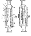
- Figure 1 is a Thermo-Hydraulically Actuated Process Control Valve disclosed herein in a closed position
- Figure 2 is the Thermo-Hydraulically Actuated Process Control Valve of Figure 1 in an open position;
- FIG. 3 is a representation of an alternate embodiment of the valve disclosed herein;
- FIG. 4 is a representation of another alternate embodiment of the valve disclosed herein;
- FIG. 5 is a representation of another embodiment of the valve disclosed herein;
- Figure 6 is a representation of another embodiment of a valve disclosed herein in a closed position
- Figure 7 is a representation of the embodiment of Figure 6 disclosed herein in an open position
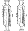
- Figure 8 is a representation of another embodiment of a valve disclosed herein in an open position.
- Figure 9 is a representation of the embodiment of Figure 8 disclosed herein in a closed position.
- a process control valve 10 includes a tubular housing 12 that is connectable in series with other tubular members (not shown) that are a part of an overall fluid management system.
- a closure member 14 capable of preventing and permitting managed fluid flow through the housing, such as a flapper.
- the closure member is in communication with a motive force transmitter 15, which is itself in operable communication with an actuation fluid discussed below.
- the flapper 14 is pivotable from a closed position to an open position about pivot 16.
- the pivot 16 is connected to the housing 12 so that a flow tube 18, in the illustrated embodiment will force the flapper 14 open upon stroking of the flow tube 18.
- a support 20 is schematically illustrated that is interactive with a power spring 22 connected to the flow tube 18 at flange 24. The flow tube when moved to the right of the Figure will cause compression of the spring 22 between the support 20 and the flange 24. The flow tube 18 will also urge the flapper 14 to the open position.
- the motive force alluded to is transmitted to the flange 24 via a piston rod 26 that is disposed within a piston cylinder 28 and includes a piston 30.
- the piston 30 includes a dynamic seal thereabout (not shown) such as a piston ring or set of rings to allow the piston to respond to fluid pressure acting thereon. It will be understood that although a discrete piston is shown, more of these may be employed or an annular piston might be substituted therefor.
- the other side of the piston 30 is exposed to an actuation fluid 31 that is contained within a sealed chamber 32.
- the chamber is an annular chamber but it is to be understood that any shape is acceptable.
- the chamber is penetrated, in the embodiment of Figures 1 and 3 , by a static seal 34 that admits at least one of a heating element 36/136 and/or energy supply conduit 35.
- the element or conduit are examples and that other things could also be admitted via the seal 34 as the particular application might require.
- the heating element 236 is disposed entirely outside of the chamber 32 and requires no penetration of the chamber 32. Power and or communication with the element 236 is supplied via line 237 entirely outside of the chamber 32. If a particular embodiment using heating element 236 has no other reason for a penetration of the chamber 32, then no seal 34 would be needed in such embodiment.
- the embodiment of Figure 4 otherwise works identically to that of the other embodiments herein including any optional configurations.
- the position sensor may be a magnetic type or other proximity sensor that allows for a confirmation of the location of the flow tube 18.
- the element 36 in Figure 1 is a rod type element and the element 136 in Figure 3 is annular configured. In each case, the element functions to heat the actuation fluid.
- the heating element 36/136 is energized and causes the temperature of the actuation fluid such as hydraulic fluid in chamber 32 to increase leading to expansion thereof.
- the coefficient of thermal expansion of the actuation fluid may be selected (by selection of a suitable fluid or by chemically modifying a fluid to custom tailor the coefficient of thermal expansion of the fluid) as desired to create the degree of motive force needed for the application.
- the piston 30 is urged toward the flapper 14 thereby causing the rod 26 to bear against the flange 24 and force the flow tube 18 to move toward the flapper 14 and to push the flapper 14 to the open position as shown in Figure 2 . Cooling of the fluid in chamber 32 will allow the flow tube to return to the position in Figure 1 pursuant to the power spring 22 urging the flow tube 18 to an unactuated position.
- the actuation fluid 31 is pre pressurized so that the amount of thermal expansion needed for actuation of the valve is less. This of course translates to less needed power for the heating element as the temperature increase necessary in the actuation fluid will be comparatively less due to the preexisting pressurization of the actuation fluid.
- Such pressurization of the fluid may be accomplished at manufacture of the valve or could be applied on site, but in the latter embodiment a static seal will be required in the chamber. In the event a static seal is already supplied as in the Figure 1 or 3 embodiments, there is no additional seal required but in the case of Figure 4 , a seal would be needed where one was not before required.
- the valve is again prepressurized but also included is a pressure dump configuration 350 so that the valve can be quickly closed.
- the dumped pressure can be to anywhere that is convenient but in keeping with the concept of having fewer seals (and no dynamic ones) between the managed fluid and atmosphere, the dump may be to a dump chamber 352 having a predetermined lower pressure than the pressure of the actuation fluid.
- the chamber will itself comprise a valve 354 of some type to admit the pressurized actuation fluid in the event a dump is desired. This may be by way of burst disk, such that increasing the pressure of the actuation fluid will automatically at a predetermined pressure threshold cause the valve to close due to rapid depressurization of the chamber 332.
- valve 354 may be externally powered through the seal 334 or may use local power source that does not require a seal 334 and as such would be used in the configuration of Figure 4 .
- heating element 236 illustrated therein may be an inductive heating element.
- valve as disclosed herein be of a fail-safe closed design.
- power spring be incorporated at all.
- an alternative embodiment utilizes two configurations of heating elements and volumes to move the flow tube in opposing directions based upon which fluid volume is energized.
- Reference to Figure 6 and 7 will make the concept clear where numerals as disclosed above are retained for one side of the device and four hundred series similar numerals are used to denote the mimicked components that will be positioned to actuate in a direction opposed to the first set of components.
- Ball valve 500 is illustrated in an open position in Figure 8 and a closed position in Figure 9 .
- the motive force to move the ball valve 500 in one direction or the other is provided by the same components as discussed with respect to Figures 6 and 7 .
- a spring configuration such as in Figure 1 .
- the flow tube 518 causes the ball valve to rotate to either a closed position from an open position or an open position from a closed position by means of rotation pins 501 incorporated on the flow tube 518 and grooves 503 on the exterior of the ball 505.
- Pivot pins 507 are also incorporated on the exterior of the ball 505 at its rotational axis.
- the rotation pins 501 engage the exterior grooves 503 on the ball causing the ball to rotate between the open and closed position.
- the configuration may also incorporate a means of translation of the ball relative to the ball seat, in addition to the rotational action described above.
Landscapes
- Engineering & Computer Science (AREA)
- General Engineering & Computer Science (AREA)
- Mechanical Engineering (AREA)
- Details Of Valves (AREA)
- Fluid-Driven Valves (AREA)
Abstract
Description
- Process control valves are used in many industries to control fluid movement for a plethora of reasons. Some of the fluids controlled by such valves are difficult to handle such that their escape from the system is undesirable. Hydrogen Sulfide is one such fluid and will be recognized by those of skill in the art as a gas that one would prefer did not escape the system in which it is housed.
- Traditional process control valves include an open or close lever that is mechanically actuated either manually or by mechanism. While such valves do control flow of the subject fluid, they also suffer from the fact that they contain a dynamic seal between the subject fluid and the environmental atmosphere. This dynamic seal exists about a shaft connected between the valve member itself and the lever. Since dynamic seals require periodic maintenance and represent a potential leak path for the subject fluid to reach environmental atmosphere and since as has been stated above it would be desirable to provide systems that more robustly contain the subject fluid within the system in which they are housed, the art would well receive alternate process control valves that improve confidence of containment.
- A thermo-hydraulically actuated valve including a housing; a closure member capable of preventing and permitting fluid flow through the housing; an actuation fluid chamber disposed at the housing and sealed from an external environment; a motive force transmitter in force transmissive communication with the closure member, the transmitter being in fluid communication with the actuation fluid chamber; and a heating element in thermal communication with the actuation fluid chamber, the valve being devoid of a dynamic seal between an area of the valve to be contacted by a managed fluid within the valve and an environment outside of the valve.
- A thermo-hydraulically actuated valve including a housing devoid of a dynamic seal between a managed fluid area of the valve and an environment outside of the valve; a closure member in the housing; an actuation fluid in pressure communication with the closure member; and an element capable of causing a change in the pressure of the actuation fluid.
- A thermo-hydraulically actuated valve including a housing devoid of a dynamic seal between a managed fluid area of the valve and an environment outside of the valve; a closure member in the housing; a first actuation fluid in pressure communication with the closure member configured to have a motive effect with respect to the closure member in one direction; a second actuation fluid in pressure communication with the closure member configured to have a motive effect with respect to the closure member in another direction; a first element capable of causing a change in the pressure of the first actuation fluid; and a second element capable of causing a change in the pressure of the second actuation fluid.
- Referring now to the drawings wherein like elements are numbered alike in the several Figures:
-
Figure 1 is a Thermo-Hydraulically Actuated Process Control Valve disclosed herein in a closed position; -
Figure 2 is the Thermo-Hydraulically Actuated Process Control Valve ofFigure 1 in an open position; -
Figure 3 is a representation of an alternate embodiment of the valve disclosed herein; -
Figure 4 is a representation of another alternate embodiment of the valve disclosed herein; -
Figure 5 is a representation of another embodiment of the valve disclosed herein; -
Figure 6 is a representation of another embodiment of a valve disclosed herein in a closed position; -
Figure 7 is a representation of the embodiment ofFigure 6 disclosed herein in an open position; -
Figure 8 is a representation of another embodiment of a valve disclosed herein in an open position; and -
Figure 9 is a representation of the embodiment ofFigure 8 disclosed herein in a closed position. - Referring to
Figure 1 , aprocess control valve 10 includes atubular housing 12 that is connectable in series with other tubular members (not shown) that are a part of an overall fluid management system. Within thehousing 12 is aclosure member 14 capable of preventing and permitting managed fluid flow through the housing, such as a flapper. The closure member is in communication with amotive force transmitter 15, which is itself in operable communication with an actuation fluid discussed below. - In the embodiment illustrated in
Figure 1 , theflapper 14 is pivotable from a closed position to an open position aboutpivot 16. Thepivot 16 is connected to thehousing 12 so that aflow tube 18, in the illustrated embodiment will force theflapper 14 open upon stroking of theflow tube 18. Asupport 20 is schematically illustrated that is interactive with apower spring 22 connected to theflow tube 18 atflange 24. The flow tube when moved to the right of the Figure will cause compression of thespring 22 between thesupport 20 and theflange 24. Theflow tube 18 will also urge theflapper 14 to the open position. If a motive force acting on the flow tube to compress thepower spring 22 is withdrawn, the spring will move theflow tube 18 toward the left of the figure and allow a torsion spring (not shown) within thepivot 16 to close theflapper 14. The motive force alluded to is transmitted to theflange 24 via apiston rod 26 that is disposed within apiston cylinder 28 and includes apiston 30. Thepiston 30 includes a dynamic seal thereabout (not shown) such as a piston ring or set of rings to allow the piston to respond to fluid pressure acting thereon. It will be understood that although a discrete piston is shown, more of these may be employed or an annular piston might be substituted therefor. The other side of thepiston 30 is exposed to anactuation fluid 31 that is contained within a sealedchamber 32. In the illustrated embodiment, the chamber is an annular chamber but it is to be understood that any shape is acceptable. The chamber is penetrated, in the embodiment ofFigures 1 and3 , by astatic seal 34 that admits at least one of aheating element 36/136 and/orenergy supply conduit 35. It is to be understood that the element or conduit are examples and that other things could also be admitted via theseal 34 as the particular application might require. Note however, in an alternate embodiment illustrated inFigure 4 that theheating element 236 is disposed entirely outside of thechamber 32 and requires no penetration of thechamber 32. Power and or communication with theelement 236 is supplied vialine 237 entirely outside of thechamber 32. If a particular embodiment usingheating element 236 has no other reason for a penetration of thechamber 32, then noseal 34 would be needed in such embodiment. The embodiment ofFigure 4 otherwise works identically to that of the other embodiments herein including any optional configurations. - It will be appreciated that other things could also be admitted through this
seal 34 if desired depending upon what might be necessary or desirable for a particular application. In the illustrated embodiment, also admitted is acommunication line 38 connected to aposition sensor 40. Because theseal 34 is static in nature, there is no significant possibility of a leak. The seal must suffer no dynamic capability and hence is by definition more reliable. - The position sensor may be a magnetic type or other proximity sensor that allows for a confirmation of the location of the
flow tube 18. - For clarity, it is noted that the
element 36 inFigure 1 is a rod type element and theelement 136 inFigure 3 is annular configured. In each case, the element functions to heat the actuation fluid. - In order to increase fluid pressure within
chamber 32, theheating element 36/136 is energized and causes the temperature of the actuation fluid such as hydraulic fluid inchamber 32 to increase leading to expansion thereof. The coefficient of thermal expansion of the actuation fluid may be selected (by selection of a suitable fluid or by chemically modifying a fluid to custom tailor the coefficient of thermal expansion of the fluid) as desired to create the degree of motive force needed for the application. Upon the heating of the fluid inchamber 32, thepiston 30 is urged toward theflapper 14 thereby causing therod 26 to bear against theflange 24 and force theflow tube 18 to move toward theflapper 14 and to push theflapper 14 to the open position as shown inFigure 2 . Cooling of the fluid inchamber 32 will allow the flow tube to return to the position inFigure 1 pursuant to thepower spring 22 urging theflow tube 18 to an unactuated position. - It is to be appreciated that the exact configuration of the invention is not limited to that illustrated in the drawings. Rather, the concept of the invention has broader reach in that it requires a fluid in a chamber that can be heated so that the fluid pressure in the chamber increases whereby the fluid causes the piston that ultimately acts on a flapper or other valve member to open the same. The use of heat and an actuation fluid to provide motive force for the change in position of a valve means that there need be no dynamic seals in the system and hence that there can be no leaks of the managed fluid within the system to the environment.
- In one embodiment, it is noted that the
actuation fluid 31 is pre pressurized so that the amount of thermal expansion needed for actuation of the valve is less. This of course translates to less needed power for the heating element as the temperature increase necessary in the actuation fluid will be comparatively less due to the preexisting pressurization of the actuation fluid. Such pressurization of the fluid may be accomplished at manufacture of the valve or could be applied on site, but in the latter embodiment a static seal will be required in the chamber. In the event a static seal is already supplied as in theFigure 1 or3 embodiments, there is no additional seal required but in the case ofFigure 4 , a seal would be needed where one was not before required. - In another embodiment, referring to
Figure 5 , the valve is again prepressurized but also included is apressure dump configuration 350 so that the valve can be quickly closed. The dumped pressure can be to anywhere that is convenient but in keeping with the concept of having fewer seals (and no dynamic ones) between the managed fluid and atmosphere, the dump may be to adump chamber 352 having a predetermined lower pressure than the pressure of the actuation fluid. The chamber will itself comprise a valve 354 of some type to admit the pressurized actuation fluid in the event a dump is desired. This may be by way of burst disk, such that increasing the pressure of the actuation fluid will automatically at a predetermined pressure threshold cause the valve to close due to rapid depressurization of thechamber 332. Alternately this may be by way of a remotely controllable valve in the same location 354 such that upon command the valve will open and reduce the actuation fluid pressure by flooding thedump chamber 352. The valve 354 may be externally powered through theseal 334 or may use local power source that does not require aseal 334 and as such would be used in the configuration ofFigure 4 . - Regardless of which type of valving method or mechanism is used to admit fluid to the
dump chamber 352, immediately upon opening of the chamber, the actuation fluid pressure will drop due to the effectively increased volume of the chamber 332 (volume of 332 plus volume of 352). - Referring again to the
Figure 4 embodiment, it is to be understood that theheating element 236 illustrated therein may be an inductive heating element. - It should be understood that it is possible not only to actuate the closure member to open and closed positions within the embodiments hereof but is also possible to actuate the closure member to any position between open and closed if desired depending upon fluid pressure applied to the piston.
- It is further to be understood that there is no requirement that the valve as disclosed herein be of a fail-safe closed design. There is no requirement that the power spring be incorporated at all. In view hereof, an alternative embodiment (see
Figures 6 and 7 ) utilizes two configurations of heating elements and volumes to move the flow tube in opposing directions based upon which fluid volume is energized. Reference toFigure 6 and 7 will make the concept clear where numerals as disclosed above are retained for one side of the device and four hundred series similar numerals are used to denote the mimicked components that will be positioned to actuate in a direction opposed to the first set of components. More specifically, and with direct reference toFigures 6 and 7 , a reader having understood the foregoing disclosure will recognize the components numbered on the left side of the Figures. The reader will also understand the four hundred series numbers on the right side of the Figures. It is noted that thefluid volumes actuation fluid volume 431, heating element 436 (note other heating means as described herein are applicable to this embodiment as well as those in which they are illustrated),piston 430/ androd 426. These are configured such that when actuated the components identified provide a motive force to retract theflow tube 418, consequently enabling theclosure member 414 to return to the closed position. The functional valve condition (open or closed) in this alternative embodiment will correspond to that actuation fluid volume which has been selectively and exclusively energized. - Referring to
Figures 8 and 9 , it is easily recognized that the embodiment is similar to the foregoingFigures 6 and 7 but the distinction therefrom, i.e. the ball valve in substitution for the flapper is equally employable for any of the other embodiments illustrated herein where a flapper is illustrated.Ball valve 500 is illustrated in an open position inFigure 8 and a closed position inFigure 9 . The motive force to move theball valve 500 in one direction or the other is provided by the same components as discussed with respect toFigures 6 and 7 . In addition, it will be appreciated that either of the sets of components in those figures could be substituted for by a spring configuration such as inFigure 1 . In embodiments where the flapper is substituted by theball valve 500, theflow tube 518 causes the ball valve to rotate to either a closed position from an open position or an open position from a closed position by means of rotation pins 501 incorporated on theflow tube 518 andgrooves 503 on the exterior of theball 505. Pivot pins 507 are also incorporated on the exterior of theball 505 at its rotational axis. As theFlow Tube 518 extends and retracts during actuation, the rotation pins 501 engage theexterior grooves 503 on the ball causing the ball to rotate between the open and closed position. The configuration may also incorporate a means of translation of the ball relative to the ball seat, in addition to the rotational action described above. - While one or more embodiments have been shown and described, modifications and substitutions may be made thereto without departing from the spirit and scope of the invention. Accordingly, it is to be understood that the present invention has been described by way of illustrations and not limitation.
Claims (18)
- A thermo-hydraulically actuated valve comprising:a housing;a closure member capable of preventing and permitting fluid flow through the housing;an actuation fluid chamber disposed at the housing and sealed from an external environment;a motive force transmitter in force transmissive communication with the closure member,the transmitter being in fluid communication with the actuation fluid chamber; anda heating element in thermal communication with the actuation fluid chamber, the valve being devoid of a dynamic seal between an area of the valve to be contacted by a managed fluid within the valve and an environment outside of the valve.
- A thermo-hydraulically actuated valve as claimed in claim 1 wherein the closure member is a flapper or a ball valve.
- A thermo-hydraulically actuated valve as claimed in claim 1 wherein the actuation fluid chamber is disposed about the housing.
- A thermo-hydraulically actuated valve as claimed in claim 1 wherein the actuation fluid chamber includes a static seal for passage of at least a component related to the heating element.
- A thermo-hydraulically actuated valve as claimed in claim 4 wherein the component is the heating element and/or an energy supply conduit for the heating element.
- A thermo-hydraulically actuated valve as claimed in claim 1 wherein the actuation fluid is hydraulic fluid or a chemically adjusted fluid to produce a desired coefficient of thermal expansion.
- A thermo-hydraulically actuated valve as claimed in claim 1 wherein the motive force transmitter includes a piston and a flow tube.
- A thermo-hydraulically actuated valve as claimed in claim 1 wherein the heating element is a rod disposed within the actuation fluid chamber or an annular member disposed within the actuation fluid chamber.
- A thermo-hydraulically actuated valve as claimed in claim 1 wherein the heating element is disposed about the housing.
- A thermo-hydraulically actuated valve as claimed in claim 1 wherein the heating element is configured without a penetration of the actuation fluid chamber.
- A thermo-hydraulically actuated valve as claimed in claim 1 wherein the heating element is an inductive heating element.
- A thermo-hydraulically actuated valve as claimed in claim 1 wherein the actuation fluid chamber further includes a fluid connection to a dump chamber.
- A thermo-hydraulically actuated valve as claimed in claim 12 wherein the dump chamber is disposed at the housing.
- A thermo-hydraulically actuated valve as claimed in claim 12 wherein the dump chamber is maintained at a pressure lower than the pressure of the actuation fluid when actuating.
- A thermo-hydraulically actuated valve as claimed in claim 12 wherein the dump chamber includes a valving mechanism.
- A thermo-hydraulically actuated valve comprising;
a housing devoid of a dynamic seal between a managed fluid area of the valve and an environment outside of the valve;
a closure member in the housing;
an actuation fluid in pressure communication with the closure member; and
an element capable of causing a change in the pressure of the actuation fluid. - A thermo-hydraulically actuated valve comprising;
a housing devoid of a dynamic seal between a managed fluid area of the valve and an environment outside of the valve;
a closure member in the housing;
a first actuation fluid in pressure communication with the closure member configured to have a motive effect with respect to the closure member in one direction;
a second actuation fluid in pressure communication with the closure member configured to have a motive effect with respect to the closure member in another direction;
a first element capable of causing a change in the pressure of the first actuation fluid; and a second element capable of causing a change in the pressure of the second actuation fluid. - A thermo-hydraulically actuated valve as claimed in claim 17 wherein one or more of the first actuation fluid and the second actuation fluid is fluidly connected to a selectively accessible dump chamber.
Applications Claiming Priority (1)
| Application Number | Priority Date | Filing Date | Title |
|---|---|---|---|
| US13/033,297 US8857785B2 (en) | 2011-02-23 | 2011-02-23 | Thermo-hydraulically actuated process control valve |
Publications (2)
| Publication Number | Publication Date |
|---|---|
| EP2492558A1 true EP2492558A1 (en) | 2012-08-29 |
| EP2492558B1 EP2492558B1 (en) | 2014-04-16 |
Family
ID=45656243
Family Applications (1)
| Application Number | Title | Priority Date | Filing Date |
|---|---|---|---|
| EP20120156278 Not-in-force EP2492558B1 (en) | 2011-02-23 | 2012-02-21 | Thermo-hydraulically actuated process control valve |
Country Status (2)
| Country | Link |
|---|---|
| US (1) | US8857785B2 (en) |
| EP (1) | EP2492558B1 (en) |
Cited By (2)
| Publication number | Priority date | Publication date | Assignee | Title |
|---|---|---|---|---|
| FR3097252A1 (en) * | 2019-06-12 | 2020-12-18 | Halliburton Energy Services, Inc. | ELECTRICAL / HYDRAULIC SAFETY VALVE |
| US11885202B2 (en) | 2019-06-12 | 2024-01-30 | Halliburton Energy Services, Inc. | Electric/hydraulic safety valve |
Families Citing this family (5)
| Publication number | Priority date | Publication date | Assignee | Title |
|---|---|---|---|---|
| US20130062071A1 (en) * | 2011-09-14 | 2013-03-14 | Schlumberger Technology Corporation | Minimal travel flow control device |
| GB2567786B (en) | 2016-10-06 | 2021-11-24 | Halliburton Energy Services Inc | Electro-hydraulic system with a single control line |
| US11015418B2 (en) * | 2018-06-06 | 2021-05-25 | Baker Hughes, A Ge Company, Llc | Tubing pressure insensitive failsafe wireline retrievable safety valve |
| US10954750B2 (en) * | 2019-07-01 | 2021-03-23 | Saudi Arabian Oil Company | Subsurface safety valve with rotating disk |
| US11732698B1 (en) | 2022-08-08 | 2023-08-22 | Hamilton Sundstrand Corporation | Ram air turbine deployment actuator heater |
Citations (5)
| Publication number | Priority date | Publication date | Assignee | Title |
|---|---|---|---|---|
| US3335997A (en) * | 1965-10-18 | 1967-08-15 | Thermal Hydraulics Inc | Valve controlled by a thermal motor |
| US4884780A (en) * | 1985-04-26 | 1989-12-05 | Nissan Motor Company, Limited | Valve actuating arrangement |
| DE10027379A1 (en) * | 2000-06-02 | 2001-12-13 | Norman Loftfield | Dosing valve for fluids or gases has housing and internal component of materials of different thermal coefficient of expansion, heated to define flow passage in housing |
| US20050000578A1 (en) * | 2001-12-19 | 2005-01-06 | Bsh Bosch Und Siemens Hausgerate Gmbh | Multiway valve |
| US20100243077A1 (en) * | 2007-07-03 | 2010-09-30 | Vetco Gray Scandinavia As | Sub sea actuator |
Family Cites Families (69)
| Publication number | Priority date | Publication date | Assignee | Title |
|---|---|---|---|---|
| US3721421A (en) * | 1970-11-12 | 1973-03-20 | United Gas Industries Ltd | Thermal actuators |
| US3778021A (en) * | 1971-02-19 | 1973-12-11 | J Alexander | Power systems for valve systems |
| US3760832A (en) * | 1971-11-11 | 1973-09-25 | Camco Inc | Heat controlled gas lift valve |
| JPS5197024A (en) * | 1975-02-22 | 1976-08-26 | Kinkyushadanyo hikagyakuben | |
| DE2749252C3 (en) * | 1977-11-03 | 1980-09-11 | Danfoss A/S, Nordborg (Daenemark) | Actuating device for adjusting the closing piece of a valve |
| US4619320A (en) * | 1984-03-02 | 1986-10-28 | Memory Metals, Inc. | Subsurface well safety valve and control system |
| US4923012A (en) | 1989-02-09 | 1990-05-08 | Baker Hughes Incorporated | Safety valve for horizontal completions of subterranean wells |
| US5343955A (en) | 1992-04-28 | 1994-09-06 | Baker Hughes Incorporated | Tandem wellbore safety valve apparatus and method of valving in a wellbore |
| US5496044A (en) | 1993-03-24 | 1996-03-05 | Baker Hughes Incorporated | Annular chamber seal |
| US5740864A (en) | 1996-01-29 | 1998-04-21 | Baker Hughes Incorporated | One-trip packer setting and whipstock-orienting method and apparatus |
| US6237683B1 (en) * | 1996-04-26 | 2001-05-29 | Camco International Inc. | Wellbore flow control device |
| US5682921A (en) | 1996-05-28 | 1997-11-04 | Baker Hughes Incorporated | Undulating transverse interface for curved flapper seal |
| US6253843B1 (en) | 1996-12-09 | 2001-07-03 | Baker Hughes Incorporated | Electric safety valve actuator |
| US6199629B1 (en) | 1997-09-24 | 2001-03-13 | Baker Hughes Incorporated | Computer controlled downhole safety valve system |
| US6173785B1 (en) | 1998-10-15 | 2001-01-16 | Baker Hughes Incorporated | Pressure-balanced rod piston control system for a subsurface safety valve |
| CA2295269C (en) | 1999-01-13 | 2008-04-08 | Baker Hughes Incorporated | Torsion spring connections for downhole flapper |
| US6321845B1 (en) * | 2000-02-02 | 2001-11-27 | Schlumberger Technology Corporation | Apparatus for device using actuator having expandable contractable element |
| US6427778B1 (en) | 2000-05-18 | 2002-08-06 | Baker Hughes Incorporated | Control system for deep set subsurface valves |
| AU784461B2 (en) | 2000-12-05 | 2006-04-06 | Baker Hughes Incorporated | Equalizing flapper for down hole safety valves |
| US6619388B2 (en) * | 2001-02-15 | 2003-09-16 | Halliburton Energy Services, Inc. | Fail safe surface controlled subsurface safety valve for use in a well |
| US6607037B2 (en) | 2001-07-24 | 2003-08-19 | Baker Hughes Incorporated | Sand control seal for subsurface safety valve |
| US6848509B2 (en) | 2001-10-22 | 2005-02-01 | Baker Hughes Incorporated | Pressure equalizing plunger valve for downhole use |
| US6957703B2 (en) | 2001-11-30 | 2005-10-25 | Baker Hughes Incorporated | Closure mechanism with integrated actuator for subsurface valves |
| WO2003062595A1 (en) | 2002-01-22 | 2003-07-31 | Baker Hughes Incorporated | System and method for a failsafe control of a downhole valve in the event of tubing rupture |
| US6695061B2 (en) * | 2002-02-27 | 2004-02-24 | Halliburton Energy Services, Inc. | Downhole tool actuating apparatus and method that utilizes a gas absorptive material |
| US20030222410A1 (en) | 2002-05-30 | 2003-12-04 | Williams Ronald D. | High pressure and temperature seal for downhole use |
| US7137452B2 (en) | 2002-09-25 | 2006-11-21 | Baker Hughes Incorporated | Method of disabling and locking open a safety valve with releasable flow tube for flapper lockout |
| US6877564B2 (en) | 2002-09-30 | 2005-04-12 | Baker Hughes Incorporated | Flapper closure mechanism |
| US6902006B2 (en) | 2002-10-03 | 2005-06-07 | Baker Hughes Incorporated | Lock open and control system access apparatus and method for a downhole safety valve |
| US7048059B2 (en) | 2002-10-15 | 2006-05-23 | Baker Hughes Incorporated | Annulus pressure control system for subsea wells |
| US7000698B2 (en) * | 2003-04-07 | 2006-02-21 | Weatherford/Lamb, Inc. | Methods and systems for optical endpoint detection of a sliding sleeve valve |
| US7255174B2 (en) | 2003-07-16 | 2007-08-14 | Baker Hughes Incorporated | Cement control ring |
| CA2636887C (en) | 2003-10-27 | 2012-03-13 | Baker Hughes Incorporated | Tubing retrievable safety valve and method |
| US8016035B2 (en) | 2003-10-27 | 2011-09-13 | Baker Hughes Incorporated | Chemical injection check valve incorporated into a tubing retrievable safety valve |
| US7367405B2 (en) * | 2004-09-03 | 2008-05-06 | Baker Hughes Incorporated | Electric pressure actuating tool and method |
| US20060157240A1 (en) | 2004-10-14 | 2006-07-20 | Shaw Brian S | Methods and apparatus for monitoring components of downhole tools |
| US7204313B2 (en) | 2005-01-07 | 2007-04-17 | Baker Hughes Incorporated | Equalizing flapper for high slam rate applications |
| US7665529B2 (en) | 2005-04-06 | 2010-02-23 | Baker Hughes Incorporated | Lubricator valve with rotational flip-flap arm |
| US7347268B2 (en) | 2005-05-18 | 2008-03-25 | Baker Hughes Incorporated | One trip flow tube exercising tool |
| US7347269B2 (en) | 2005-05-18 | 2008-03-25 | Baker Hughes Incorporated | Flow tube exercising tool |
| US7493956B2 (en) | 2006-03-16 | 2009-02-24 | Baker Hughes Incorporated | Subsurface safety valve with closure provided by the flowing medium |
| US7987914B2 (en) * | 2006-06-07 | 2011-08-02 | Schlumberger Technology Corporation | Controlling actuation of tools in a wellbore with a phase change material |
| US7694742B2 (en) | 2006-09-18 | 2010-04-13 | Baker Hughes Incorporated | Downhole hydraulic control system with failsafe features |
| US8225871B2 (en) | 2006-11-09 | 2012-07-24 | Baker Hughes Incorporated | Bidirectional sealing mechanically shifted ball valve for downhole use |
| US7591317B2 (en) | 2006-11-09 | 2009-09-22 | Baker Hughes Incorporated | Tubing pressure insensitive control system |
| US7810571B2 (en) | 2006-11-09 | 2010-10-12 | Baker Hughes Incorporated | Downhole lubricator valve |
| US7699108B2 (en) | 2006-11-13 | 2010-04-20 | Baker Hughes Incorporated | Distortion compensation for rod piston bore in subsurface safety valves |
| US7650945B2 (en) | 2006-11-13 | 2010-01-26 | Baker Hughes Incorporated | Inflatable closure system |
| US7552774B2 (en) | 2006-12-05 | 2009-06-30 | Baker Hughes Incorporated | Control line hydrostatic minimally sensitive control system |
| US7665518B2 (en) | 2006-12-20 | 2010-02-23 | Baker Hughes Incorporated | Method of using a charged chamber pressure transmitter for subsurface safety valves |
| US7604056B2 (en) | 2007-03-07 | 2009-10-20 | Baker Hughes Incorporated | Downhole valve and method of making |
| US8701782B2 (en) | 2007-03-26 | 2014-04-22 | Baker Hughes Incorporated | Subsurface safety valve with metal seal |
| US20080314599A1 (en) | 2007-06-21 | 2008-12-25 | Bane Darren E | Tubing Pressure Balanced Operating System with Low Operating Pressure |
| US7637324B2 (en) | 2007-07-03 | 2009-12-29 | Baker Hughes Incorporated | Isolation valve for subsurface safety valve line |
| US8056618B2 (en) | 2007-07-18 | 2011-11-15 | Baker Hughes Incorporated | Flapper mounted equalizer valve for subsurface safety valves |
| US20090038804A1 (en) | 2007-08-09 | 2009-02-12 | Going Iii Walter S | Subsurface Safety Valve for Electric Subsea Tree |
| US7762335B2 (en) | 2007-08-23 | 2010-07-27 | Baker Hughes Incorporated | Switching apparatus between independent control systems for a subsurface safety valve |
| US7703532B2 (en) | 2007-09-17 | 2010-04-27 | Baker Hughes Incorporated | Tubing retrievable injection valve |
| US7708075B2 (en) | 2007-10-26 | 2010-05-04 | Baker Hughes Incorporated | System and method for injecting a chemical downhole of a tubing retrievable capillary bypass safety valve |
| US7621327B2 (en) | 2007-10-31 | 2009-11-24 | Baker Hughes Incorporated | Downhole seal bore repair device |
| US7743833B2 (en) | 2008-01-24 | 2010-06-29 | Baker Hughes Incorporated | Pressure balanced piston for subsurface safety valves |
| US8002042B2 (en) | 2008-03-17 | 2011-08-23 | Baker Hughes Incorporated | Actuatable subsurface safety valve and method |
| US20090236099A1 (en) | 2008-03-24 | 2009-09-24 | Burris John E | Multiple Spring Subsurface Safety Valve |
| US7779907B2 (en) | 2008-03-25 | 2010-08-24 | Baker Hughes Incorporated | Downhole shock absorber with crushable nose |
| US8176975B2 (en) | 2008-04-07 | 2012-05-15 | Baker Hughes Incorporated | Tubing pressure insensitive actuator system and method |
| US7669661B2 (en) | 2008-06-20 | 2010-03-02 | Baker Hughes Incorporated | Thermally expansive fluid actuator devices for downhole tools and methods of actuating downhole tools using same |
| US7717185B2 (en) | 2008-07-14 | 2010-05-18 | Baker Hughes Incorporatd | Lock open and control system access apparatus for a downhole safety valve |
| US7967074B2 (en) | 2008-07-29 | 2011-06-28 | Baker Hughes Incorporated | Electric wireline insert safety valve |
| US8424842B2 (en) | 2009-04-15 | 2013-04-23 | Baker Hughes Incorporated | Rotationally-actuated flapper valve and method |
-
2011
- 2011-02-23 US US13/033,297 patent/US8857785B2/en active Active
-
2012
- 2012-02-21 EP EP20120156278 patent/EP2492558B1/en not_active Not-in-force
Patent Citations (5)
| Publication number | Priority date | Publication date | Assignee | Title |
|---|---|---|---|---|
| US3335997A (en) * | 1965-10-18 | 1967-08-15 | Thermal Hydraulics Inc | Valve controlled by a thermal motor |
| US4884780A (en) * | 1985-04-26 | 1989-12-05 | Nissan Motor Company, Limited | Valve actuating arrangement |
| DE10027379A1 (en) * | 2000-06-02 | 2001-12-13 | Norman Loftfield | Dosing valve for fluids or gases has housing and internal component of materials of different thermal coefficient of expansion, heated to define flow passage in housing |
| US20050000578A1 (en) * | 2001-12-19 | 2005-01-06 | Bsh Bosch Und Siemens Hausgerate Gmbh | Multiway valve |
| US20100243077A1 (en) * | 2007-07-03 | 2010-09-30 | Vetco Gray Scandinavia As | Sub sea actuator |
Cited By (3)
| Publication number | Priority date | Publication date | Assignee | Title |
|---|---|---|---|---|
| FR3097252A1 (en) * | 2019-06-12 | 2020-12-18 | Halliburton Energy Services, Inc. | ELECTRICAL / HYDRAULIC SAFETY VALVE |
| US11668161B2 (en) | 2019-06-12 | 2023-06-06 | Halliburton Energy Services, Inc. | Electric/hydraulic safety valve |
| US11885202B2 (en) | 2019-06-12 | 2024-01-30 | Halliburton Energy Services, Inc. | Electric/hydraulic safety valve |
Also Published As
| Publication number | Publication date |
|---|---|
| US20120211680A1 (en) | 2012-08-23 |
| EP2492558B1 (en) | 2014-04-16 |
| US8857785B2 (en) | 2014-10-14 |
Similar Documents
| Publication | Publication Date | Title |
|---|---|---|
| EP2492558B1 (en) | Thermo-hydraulically actuated process control valve | |
| JP6169735B2 (en) | Device for increasing the force of an actuator having an override device | |
| JP5864605B2 (en) | Slide stem control valve assembly and operating method thereof | |
| CN102292582B (en) | Actuator having override apparatus | |
| EP2870415B1 (en) | Fail-safe actuating system | |
| NO348245B1 (en) | Flow Control Assembly Actuated by Pilot Pressure | |
| GB2414753A (en) | Integrated control of multiple well tools | |
| GB2617786A (en) | Electric remote operated gas lift mandrel | |
| WO2017077345A1 (en) | Circulation subassembly | |
| NO340667B1 (en) | subsea | |
| CN106415025B (en) | Servo valve | |
| WO2005098297A2 (en) | Valve, actuator and control system therefor | |
| AU2015281295B2 (en) | High Integrity Pressure Protecting System (HIPPS) for a fluid line | |
| CN107965484B (en) | Valve and hydraulic control device with such a valve | |
| US10472924B2 (en) | Apparatus and methods for manual override of hydraulic choke or valve actuators | |
| RU2267682C1 (en) | Stop control valve | |
| RU2386880C1 (en) | Isolation stop and control valve | |
| US12385354B2 (en) | Safety valve, method, and system | |
| EP3628898B1 (en) | Three-position poppet valve | |
| KR20010013329A (en) | Actuator valve for pressure switch for a hydraulic system | |
| CN107636340B (en) | Hydraulic system with clutch operating device that minimizes pump losses | |
| RU2830961C1 (en) | Downhole electric valve with electrohydraulic drive | |
| EP3875815B1 (en) | Hose test system and method | |
| US12460737B2 (en) | Line break device | |
| CA2996929A1 (en) | Electro-hydraulic valve actuator having modular manifold with configurable redundancy |
Legal Events
| Date | Code | Title | Description |
|---|---|---|---|
| PUAI | Public reference made under article 153(3) epc to a published international application that has entered the european phase |
Free format text: ORIGINAL CODE: 0009012 |
|
| AK | Designated contracting states |
Kind code of ref document: A1 Designated state(s): AL AT BE BG CH CY CZ DE DK EE ES FI FR GB GR HR HU IE IS IT LI LT LU LV MC MK MT NL NO PL PT RO RS SE SI SK SM TR |
|
| AX | Request for extension of the european patent |
Extension state: BA ME |
|
| 17P | Request for examination filed |
Effective date: 20130208 |
|
| RIC1 | Information provided on ipc code assigned before grant |
Ipc: F16K 31/02 20060101AFI20130326BHEP |
|
| GRAP | Despatch of communication of intention to grant a patent |
Free format text: ORIGINAL CODE: EPIDOSNIGR1 |
|
| INTG | Intention to grant announced |
Effective date: 20130523 |
|
| GRAS | Grant fee paid |
Free format text: ORIGINAL CODE: EPIDOSNIGR3 |
|
| GRAP | Despatch of communication of intention to grant a patent |
Free format text: ORIGINAL CODE: EPIDOSNIGR1 |
|
| INTG | Intention to grant announced |
Effective date: 20130924 |
|
| GRAA | (expected) grant |
Free format text: ORIGINAL CODE: 0009210 |
|
| AK | Designated contracting states |
Kind code of ref document: B1 Designated state(s): AL AT BE BG CH CY CZ DE DK EE ES FI FR GB GR HR HU IE IS IT LI LT LU LV MC MK MT NL NO PL PT RO RS SE SI SK SM TR |
|
| REG | Reference to a national code |
Ref country code: GB Ref legal event code: FG4D |
|
| REG | Reference to a national code |
Ref country code: CH Ref legal event code: EP |
|
| REG | Reference to a national code |
Ref country code: AT Ref legal event code: REF Ref document number: 662781 Country of ref document: AT Kind code of ref document: T Effective date: 20140515 |
|
| REG | Reference to a national code |
Ref country code: IE Ref legal event code: FG4D |
|
| REG | Reference to a national code |
Ref country code: NL Ref legal event code: T3 Ref country code: DE Ref legal event code: R096 Ref document number: 602012001395 Country of ref document: DE Effective date: 20140528 |
|
| REG | Reference to a national code |
Ref country code: AT Ref legal event code: MK05 Ref document number: 662781 Country of ref document: AT Kind code of ref document: T Effective date: 20140416 |
|
| REG | Reference to a national code |
Ref country code: LT Ref legal event code: MG4D |
|
| PG25 | Lapsed in a contracting state [announced via postgrant information from national office to epo] |
Ref country code: NO Free format text: LAPSE BECAUSE OF FAILURE TO SUBMIT A TRANSLATION OF THE DESCRIPTION OR TO PAY THE FEE WITHIN THE PRESCRIBED TIME-LIMIT Effective date: 20140716 Ref country code: GR Free format text: LAPSE BECAUSE OF FAILURE TO SUBMIT A TRANSLATION OF THE DESCRIPTION OR TO PAY THE FEE WITHIN THE PRESCRIBED TIME-LIMIT Effective date: 20140717 Ref country code: CY Free format text: LAPSE BECAUSE OF FAILURE TO SUBMIT A TRANSLATION OF THE DESCRIPTION OR TO PAY THE FEE WITHIN THE PRESCRIBED TIME-LIMIT Effective date: 20140416 Ref country code: IS Free format text: LAPSE BECAUSE OF FAILURE TO SUBMIT A TRANSLATION OF THE DESCRIPTION OR TO PAY THE FEE WITHIN THE PRESCRIBED TIME-LIMIT Effective date: 20140816 Ref country code: LT Free format text: LAPSE BECAUSE OF FAILURE TO SUBMIT A TRANSLATION OF THE DESCRIPTION OR TO PAY THE FEE WITHIN THE PRESCRIBED TIME-LIMIT Effective date: 20140416 Ref country code: FI Free format text: LAPSE BECAUSE OF FAILURE TO SUBMIT A TRANSLATION OF THE DESCRIPTION OR TO PAY THE FEE WITHIN THE PRESCRIBED TIME-LIMIT Effective date: 20140416 Ref country code: BG Free format text: LAPSE BECAUSE OF FAILURE TO SUBMIT A TRANSLATION OF THE DESCRIPTION OR TO PAY THE FEE WITHIN THE PRESCRIBED TIME-LIMIT Effective date: 20140716 |
|
| PG25 | Lapsed in a contracting state [announced via postgrant information from national office to epo] |
Ref country code: ES Free format text: LAPSE BECAUSE OF FAILURE TO SUBMIT A TRANSLATION OF THE DESCRIPTION OR TO PAY THE FEE WITHIN THE PRESCRIBED TIME-LIMIT Effective date: 20140416 Ref country code: SE Free format text: LAPSE BECAUSE OF FAILURE TO SUBMIT A TRANSLATION OF THE DESCRIPTION OR TO PAY THE FEE WITHIN THE PRESCRIBED TIME-LIMIT Effective date: 20140416 Ref country code: AT Free format text: LAPSE BECAUSE OF FAILURE TO SUBMIT A TRANSLATION OF THE DESCRIPTION OR TO PAY THE FEE WITHIN THE PRESCRIBED TIME-LIMIT Effective date: 20140416 Ref country code: HR Free format text: LAPSE BECAUSE OF FAILURE TO SUBMIT A TRANSLATION OF THE DESCRIPTION OR TO PAY THE FEE WITHIN THE PRESCRIBED TIME-LIMIT Effective date: 20140416 Ref country code: RS Free format text: LAPSE BECAUSE OF FAILURE TO SUBMIT A TRANSLATION OF THE DESCRIPTION OR TO PAY THE FEE WITHIN THE PRESCRIBED TIME-LIMIT Effective date: 20140416 Ref country code: LV Free format text: LAPSE BECAUSE OF FAILURE TO SUBMIT A TRANSLATION OF THE DESCRIPTION OR TO PAY THE FEE WITHIN THE PRESCRIBED TIME-LIMIT Effective date: 20140416 Ref country code: PL Free format text: LAPSE BECAUSE OF FAILURE TO SUBMIT A TRANSLATION OF THE DESCRIPTION OR TO PAY THE FEE WITHIN THE PRESCRIBED TIME-LIMIT Effective date: 20140416 |
|
| PG25 | Lapsed in a contracting state [announced via postgrant information from national office to epo] |
Ref country code: PT Free format text: LAPSE BECAUSE OF FAILURE TO SUBMIT A TRANSLATION OF THE DESCRIPTION OR TO PAY THE FEE WITHIN THE PRESCRIBED TIME-LIMIT Effective date: 20140818 |
|
| REG | Reference to a national code |
Ref country code: DE Ref legal event code: R097 Ref document number: 602012001395 Country of ref document: DE |
|
| PG25 | Lapsed in a contracting state [announced via postgrant information from national office to epo] |
Ref country code: CZ Free format text: LAPSE BECAUSE OF FAILURE TO SUBMIT A TRANSLATION OF THE DESCRIPTION OR TO PAY THE FEE WITHIN THE PRESCRIBED TIME-LIMIT Effective date: 20140416 Ref country code: DK Free format text: LAPSE BECAUSE OF FAILURE TO SUBMIT A TRANSLATION OF THE DESCRIPTION OR TO PAY THE FEE WITHIN THE PRESCRIBED TIME-LIMIT Effective date: 20140416 Ref country code: EE Free format text: LAPSE BECAUSE OF FAILURE TO SUBMIT A TRANSLATION OF THE DESCRIPTION OR TO PAY THE FEE WITHIN THE PRESCRIBED TIME-LIMIT Effective date: 20140416 Ref country code: SK Free format text: LAPSE BECAUSE OF FAILURE TO SUBMIT A TRANSLATION OF THE DESCRIPTION OR TO PAY THE FEE WITHIN THE PRESCRIBED TIME-LIMIT Effective date: 20140416 |
|
| PLBE | No opposition filed within time limit |
Free format text: ORIGINAL CODE: 0009261 |
|
| STAA | Information on the status of an ep patent application or granted ep patent |
Free format text: STATUS: NO OPPOSITION FILED WITHIN TIME LIMIT |
|
| 26N | No opposition filed |
Effective date: 20150119 |
|
| PG25 | Lapsed in a contracting state [announced via postgrant information from national office to epo] |
Ref country code: IT Free format text: LAPSE BECAUSE OF FAILURE TO SUBMIT A TRANSLATION OF THE DESCRIPTION OR TO PAY THE FEE WITHIN THE PRESCRIBED TIME-LIMIT Effective date: 20140416 |
|
| REG | Reference to a national code |
Ref country code: DE Ref legal event code: R097 Ref document number: 602012001395 Country of ref document: DE Effective date: 20150119 |
|
| PG25 | Lapsed in a contracting state [announced via postgrant information from national office to epo] |
Ref country code: SI Free format text: LAPSE BECAUSE OF FAILURE TO SUBMIT A TRANSLATION OF THE DESCRIPTION OR TO PAY THE FEE WITHIN THE PRESCRIBED TIME-LIMIT Effective date: 20140416 |
|
| REG | Reference to a national code |
Ref country code: DE Ref legal event code: R119 Ref document number: 602012001395 Country of ref document: DE |
|
| REG | Reference to a national code |
Ref country code: CH Ref legal event code: PL |
|
| PG25 | Lapsed in a contracting state [announced via postgrant information from national office to epo] |
Ref country code: LI Free format text: LAPSE BECAUSE OF NON-PAYMENT OF DUE FEES Effective date: 20150228 Ref country code: CH Free format text: LAPSE BECAUSE OF NON-PAYMENT OF DUE FEES Effective date: 20150228 Ref country code: MC Free format text: LAPSE BECAUSE OF FAILURE TO SUBMIT A TRANSLATION OF THE DESCRIPTION OR TO PAY THE FEE WITHIN THE PRESCRIBED TIME-LIMIT Effective date: 20140416 |
|
| REG | Reference to a national code |
Ref country code: IE Ref legal event code: MM4A |
|
| REG | Reference to a national code |
Ref country code: FR Ref legal event code: ST Effective date: 20151030 |
|
| PG25 | Lapsed in a contracting state [announced via postgrant information from national office to epo] |
Ref country code: DE Free format text: LAPSE BECAUSE OF NON-PAYMENT OF DUE FEES Effective date: 20150901 Ref country code: IE Free format text: LAPSE BECAUSE OF NON-PAYMENT OF DUE FEES Effective date: 20150221 |
|
| PG25 | Lapsed in a contracting state [announced via postgrant information from national office to epo] |
Ref country code: FR Free format text: LAPSE BECAUSE OF NON-PAYMENT OF DUE FEES Effective date: 20150302 |
|
| GBPC | Gb: european patent ceased through non-payment of renewal fee |
Effective date: 20160221 |
|
| PG25 | Lapsed in a contracting state [announced via postgrant information from national office to epo] |
Ref country code: MT Free format text: LAPSE BECAUSE OF FAILURE TO SUBMIT A TRANSLATION OF THE DESCRIPTION OR TO PAY THE FEE WITHIN THE PRESCRIBED TIME-LIMIT Effective date: 20140416 |
|
| PG25 | Lapsed in a contracting state [announced via postgrant information from national office to epo] |
Ref country code: GB Free format text: LAPSE BECAUSE OF NON-PAYMENT OF DUE FEES Effective date: 20160221 |
|
| PG25 | Lapsed in a contracting state [announced via postgrant information from national office to epo] |
Ref country code: SM Free format text: LAPSE BECAUSE OF FAILURE TO SUBMIT A TRANSLATION OF THE DESCRIPTION OR TO PAY THE FEE WITHIN THE PRESCRIBED TIME-LIMIT Effective date: 20140416 Ref country code: RO Free format text: LAPSE BECAUSE OF FAILURE TO SUBMIT A TRANSLATION OF THE DESCRIPTION OR TO PAY THE FEE WITHIN THE PRESCRIBED TIME-LIMIT Effective date: 20140416 Ref country code: HU Free format text: LAPSE BECAUSE OF FAILURE TO SUBMIT A TRANSLATION OF THE DESCRIPTION OR TO PAY THE FEE WITHIN THE PRESCRIBED TIME-LIMIT; INVALID AB INITIO Effective date: 20120221 |
|
| PG25 | Lapsed in a contracting state [announced via postgrant information from national office to epo] |
Ref country code: TR Free format text: LAPSE BECAUSE OF FAILURE TO SUBMIT A TRANSLATION OF THE DESCRIPTION OR TO PAY THE FEE WITHIN THE PRESCRIBED TIME-LIMIT Effective date: 20140416 |
|
| PG25 | Lapsed in a contracting state [announced via postgrant information from national office to epo] |
Ref country code: MK Free format text: LAPSE BECAUSE OF FAILURE TO SUBMIT A TRANSLATION OF THE DESCRIPTION OR TO PAY THE FEE WITHIN THE PRESCRIBED TIME-LIMIT Effective date: 20140416 |
|
| PG25 | Lapsed in a contracting state [announced via postgrant information from national office to epo] |
Ref country code: AL Free format text: LAPSE BECAUSE OF FAILURE TO SUBMIT A TRANSLATION OF THE DESCRIPTION OR TO PAY THE FEE WITHIN THE PRESCRIBED TIME-LIMIT Effective date: 20140416 |
|
| PGFP | Annual fee paid to national office [announced via postgrant information from national office to epo] |
Ref country code: BE Payment date: 20181217 Year of fee payment: 8 |
|
| PGFP | Annual fee paid to national office [announced via postgrant information from national office to epo] |
Ref country code: LU Payment date: 20190124 Year of fee payment: 8 |
|
| PGFP | Annual fee paid to national office [announced via postgrant information from national office to epo] |
Ref country code: NL Payment date: 20190128 Year of fee payment: 8 |
|
| REG | Reference to a national code |
Ref country code: NL Ref legal event code: MM Effective date: 20200301 |
|
| REG | Reference to a national code |
Ref country code: BE Ref legal event code: MM Effective date: 20200229 |
|
| PG25 | Lapsed in a contracting state [announced via postgrant information from national office to epo] |
Ref country code: LU Free format text: LAPSE BECAUSE OF NON-PAYMENT OF DUE FEES Effective date: 20200221 |
|
| PG25 | Lapsed in a contracting state [announced via postgrant information from national office to epo] |
Ref country code: NL Free format text: LAPSE BECAUSE OF NON-PAYMENT OF DUE FEES Effective date: 20200301 |
|
| PG25 | Lapsed in a contracting state [announced via postgrant information from national office to epo] |
Ref country code: BE Free format text: LAPSE BECAUSE OF NON-PAYMENT OF DUE FEES Effective date: 20200229 |
|
| P01 | Opt-out of the competence of the unified patent court (upc) registered |
Effective date: 20230526 |