EP2492552A1 - Ball valve having multiple moveable seats - Google Patents
Ball valve having multiple moveable seats Download PDFInfo
- Publication number
- EP2492552A1 EP2492552A1 EP12154842A EP12154842A EP2492552A1 EP 2492552 A1 EP2492552 A1 EP 2492552A1 EP 12154842 A EP12154842 A EP 12154842A EP 12154842 A EP12154842 A EP 12154842A EP 2492552 A1 EP2492552 A1 EP 2492552A1
- Authority
- EP
- European Patent Office
- Prior art keywords
- seat
- housing
- valve ball
- valve assembly
- sealing surface
- Prior art date
- Legal status (The legal status is an assumption and is not a legal conclusion. Google has not performed a legal analysis and makes no representation as to the accuracy of the status listed.)
- Granted
Links
- 238000007789 sealing Methods 0.000 claims abstract description 131
- 238000000034 method Methods 0.000 claims abstract description 12
- 230000007246 mechanism Effects 0.000 claims description 27
- 239000012530 fluid Substances 0.000 claims description 26
- 239000002184 metal Substances 0.000 claims description 15
- 238000004519 manufacturing process Methods 0.000 claims description 2
- 230000008878 coupling Effects 0.000 claims 1
- 238000010168 coupling process Methods 0.000 claims 1
- 238000005859 coupling reaction Methods 0.000 claims 1
- 238000000576 coating method Methods 0.000 description 10
- 239000011248 coating agent Substances 0.000 description 9
- 238000011144 upstream manufacturing Methods 0.000 description 5
- 238000000429 assembly Methods 0.000 description 3
- 230000000712 assembly Effects 0.000 description 3
- 230000008901 benefit Effects 0.000 description 3
- OKTJSMMVPCPJKN-UHFFFAOYSA-N Carbon Chemical compound [C] OKTJSMMVPCPJKN-UHFFFAOYSA-N 0.000 description 2
- 239000000463 material Substances 0.000 description 2
- 239000003566 sealing material Substances 0.000 description 2
- 230000000903 blocking effect Effects 0.000 description 1
- 230000008859 change Effects 0.000 description 1
- 210000004907 gland Anatomy 0.000 description 1
- 230000003993 interaction Effects 0.000 description 1
- 230000008569 process Effects 0.000 description 1
Images


Classifications
-
- F—MECHANICAL ENGINEERING; LIGHTING; HEATING; WEAPONS; BLASTING
- F16—ENGINEERING ELEMENTS AND UNITS; GENERAL MEASURES FOR PRODUCING AND MAINTAINING EFFECTIVE FUNCTIONING OF MACHINES OR INSTALLATIONS; THERMAL INSULATION IN GENERAL
- F16K—VALVES; TAPS; COCKS; ACTUATING-FLOATS; DEVICES FOR VENTING OR AERATING
- F16K5/00—Plug valves; Taps or cocks comprising only cut-off apparatus having at least one of the sealing faces shaped as a more or less complete surface of a solid of revolution, the opening and closing movement being predominantly rotary
- F16K5/06—Plug valves; Taps or cocks comprising only cut-off apparatus having at least one of the sealing faces shaped as a more or less complete surface of a solid of revolution, the opening and closing movement being predominantly rotary with plugs having spherical surfaces; Packings therefor
- F16K5/0663—Packings
- F16K5/0673—Composite packings
- F16K5/0678—Composite packings in which only one of the components of the composite packing is contacting the plug
-
- Y—GENERAL TAGGING OF NEW TECHNOLOGICAL DEVELOPMENTS; GENERAL TAGGING OF CROSS-SECTIONAL TECHNOLOGIES SPANNING OVER SEVERAL SECTIONS OF THE IPC; TECHNICAL SUBJECTS COVERED BY FORMER USPC CROSS-REFERENCE ART COLLECTIONS [XRACs] AND DIGESTS
- Y10—TECHNICAL SUBJECTS COVERED BY FORMER USPC
- Y10T—TECHNICAL SUBJECTS COVERED BY FORMER US CLASSIFICATION
- Y10T29/00—Metal working
- Y10T29/49—Method of mechanical manufacture
- Y10T29/49405—Valve or choke making
- Y10T29/49409—Valve seat forming
Definitions
- Embodiments disclosed herein generally relate to methods and assemblies that include a valve ball used to start and stop fluid flow. More specifically, embodiments disclosed herein relate to a valve assembly having a valve ball with multiple moveable seats to seal against fluid flow from the upstream and/or the downstream direction.
- Ball valves typically include a valve ball that is located between two seats in the middle of a passage.
- the valve ball has a through hole, and can be rotated between two positions.
- U.S. Patent No. 5,246,203, issued to McKnight et al . (“McKnight”) discloses an oilfield valve that incorporates a ball valve mechanism. The mechanics of a typical ball valve mechanism are demonstrated in the McKnight patent.
- the through hole of the valve ball will align with the passage of the pipe or drill string. This position will generally allow complete and undisrupted fluid flow through the passage.
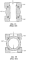
- the valve ball may then be rotated from this position into a second position, as demonstrated in Figure 1B , to be misaligned with the passage of the pipe, thereby disrupting fluid flow.
- the valve ball coupled with the two seats sealing against the valve ball, may stop fluid flow through the pipe passage when the valve ball is positioned in the closed position to misalign with the through hole passage by having the seats seal up against the valve ball.
- a seal is made between the seats, 101 and 102, and the valve ball 105 to completely prohibit flow through the passage.
- the valve ball has the ability to seal against the seats to be effective against even the highest of pressures, allowing the arrangement to be used as a ball valve.
- valve ball 105 when the valve ball 105 is in the second position, blocking flow through the passage, as seen in Figure 1B , the valve ball 105 may not be able to effectively seal against the fluid flow, such as both in the upstream and downstream direction. For example, debris comes between the valve ball 105 and the seat 102, only sealing on the downstream seat 101 may be achieved. In such an example, if a fluid force is applied from the downstream direction, the debris may cause the valve to be unable to effectively seal between the valve ball 105 and the seat 102, thereby resulting in a leakage through the ball valve arrangement.
- valve ball 105 is usually fixed in all directions, except for rotating between an open and closed position, the seats 101 and 102 must be perfectly aligned with the valve ball 105 to ensure proper sealing engagement between the seats 101 and 102 and the valve ball 105. If the valve ball 105 shifts in any direction, such as towards either side with respect to the seats 101 and 102, then one or both of the seats 101 and 102 may lose effective sealing engagement with the valve ball 105.
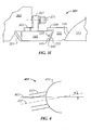
- Figures 2A and 2B show a valve assembly having a seat 201 and a valve ball 205 disposed adjacent to each other with respect to an axis 200 of the valve assembly.
- the seat 201 and the valve ball 205 are aligned with each other to ensure proper sealing engagement therebetween.
- the valve ball 205 has shifted with respect to the seat 201 and the axis 200 such that the seat 201 and the valve ball 205 have lost proper sealing engagement therebetween.
- the seat 201 may not be able to move side-to-side and/or rotate with respect to the valve ball 205, such as having the seat 201 move radially with respect to the axis 200. As such, the seat 201 and the valve ball 205 may lose proper sealing engagement therebetween. Though the movement between the valve ball 205 and the seat 201 may be exaggerated and not drawn to scale in Figure 2B , this type of movement and shifting between the valve ball 205 and the seat 201 may demonstrate how even minor movements may lead to a loss of proper sealing within a valve assembly, particularly within a valve assembly having metal-to-metal seals.
- valve assembly in one aspect, includes a housing having a passage formed therethrough, and a valve ball having a through hole and disposed in the housing, in which the valve ball is rotatable between an open position that has the through hole substantially aligned with the passage and a closed position that has the through hole substantially misaligned with the passage.
- the valve assembly further includes a first seat having a first sealing surface and disposed in the housing adjacent to the valve ball, and a second seat having a second sealing surface and disposed in the housing adjacent to the first seat such that the first sealing surface of the first seat is disposed adjacent to the second sealing surface of the second seat, in which at least one of the first sealing surface of the first seat and the second sealing surface of the second seat includes an arcuate surface.
- the first seat is configured to precess with respect to an axis extending through the housing, and the second seat is configured to move along the axis extending through the housing.
- the first seat is configured to precess up to about 5 degrees with respect to the axis extending through the housing.
- the first seat is configured to precess up to about 1 degree with respect to the axis extending through the housing.
- valve assembly further comprises a stop shoulder disposed within the housing such that the stop shoulder is configured to limit the precess of the first seat with respect to the axis extending through the housing.
- the stop shoulder is attached to the first seat.
- valve assembly further comprises a sealing element disposed between the first sealing surface of the first seat and the second sealing surface of the second seat.
- valve assembly further comprises a sealing element disposed between the second seat and the housing.
- valve ball and the first seat are mate-lapped together and are configured to form a seal therebetween, and wherein the first seat and the second seat are mate-lapped together and are configured to form another seal therebetween
- valve assembly in another aspect, includes a housing having a passage formed therethrough about a first axis, and a valve ball having a through hole formed therethrough about a second axis, in which the valve ball is configured to rotate between an open position such that the first axis of the housing is substantially aligned with the second axis of the valve ball and a closed position such that the first axis of the housing is substantially misaligned with the second axis of the valve ball.
- the valve assembly further includes a stem extending through an opening formed in the housing and coupled to the valve ball such that the stem is configured to rotate the valve ball between the open position and the closed position, a first seat having a first sealing surface and disposed in the housing adjacent to the valve ball on one side of the valve ball, and a second seat having a second sealing surface and disposed in the housing adjacent to the first seat such that the first sealing surface of the first seat is disposed adjacent to the second sealing surface of the second seat, in which at least one of the first sealing surface of the first seat and the second sealing surface of the second seat includes an arcuate surface.
- the first sealing surface of the first seat comprises a first arcuate surface
- the second sealing surface of the second seat comprises a second arcuate surface
- the at least one of the first sealing surface of the first seat and the second sealing surface of the second seat comprise a spherical surface.
- another of the first sealing surface of the first seat and the second sealing surface of the second seat comprises a tapered surface.
- valve assembly further comprises a biasing mechanism disposed, at least partially, between the housing and the second seat, wherein the biasing mechanism biases at least one of the first seat and the second seat towards the valve ball.
- the valve assembly further comprises a third seat, wherein the third seat is disposed on another side of the valve ball with respect to the first seat, and wherein, during one direction of fluid flow, the valve ball is configured to form a metal-to-metal seal with the first seat, and during another direction of fluid flow, the valve ball is configured to form a metal-to-metal seal with the third seat.
- the first seat is configured to precess with respect to the first axis extending through the housing, and wherein the second seat is configured to move along the first axis extending through the housing.
- embodiments disclosed herein relate to a method to manufacture a valve assembly.
- the method includes disposing a first seat having a first sealing surface in a housing, the housing having a passage formed therethrough, and disposing a second seat having a second sealing surface in the housing adjacent to the first seat such that the first sealing surface of the first seat is adjacent to the second sealing surface of the second seat, in which at least one of the first sealing surface of the first seat and the second sealing surface of the second seat includes an arcuate surface.
- the method further includes disposing a valve ball having a through hole formed therein in the housing adjacent to the first seat such that the valve ball is rotatable within the housing between an open position that has the through hole substantially aligned with the passage and a closed position that has the through hole substantially misaligned with the passage.
- the at least one of the first sealing surface of the first seat and the second sealing surface of the second seat comprise a spherical surface.
- another of the first sealing surface of the first seat and the second sealing surface of the second seat comprises a tapered surface.
- Figures 1A and 1B show cross-sectional views of a ball valve assembly according to the prior art.
- Figures 2A and 2B show cross-sectional views of a ball valve assembly according to the prior art.
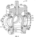
- FIGS. 3A-3E show multiple views of a valve assembly in accordance with embodiments disclosed herein.
- Figure 4 shows a cross-sectional view of a valve assembly in accordance with embodiments disclosed herein.
- Figure 5 shows a perspective view of a valve assembly in accordance with embodiments disclosed herein.
- valve assembly and particularly a ball valve assembly, that is used to start and stop fluid flow therethrough.
- the valve assembly may include a housing having a passage formed therethrough, in which the passage may be formed about a first axis.
- the valve assembly may further include a valve ball having a through hole formed therethrough, in which the through hole may be formed about a second axis.
- the valve ball is disposed within the housing such that the valve ball is rotatable between an open position and a closed position within the housing.
- the through hole of the valve ball may align with the passage of the housing, such as by having the second axis of the through hole substantially align with the first axis of the passage, thereby generally enabling fluid flow therethrough.
- the through hole of the valve ball may substantially misalign with the passage of the housing, such as by having the second axis of the through hole substantially misalign with the first axis of the passage, thereby generally prohibiting fluid flow therethrough.
- the valve assembly includes a first seat having a first sealing surface, in which the first seat is disposed within the housing, and includes a second seat having a second sealing surface, in which the second seat is also disposed in the housing.
- the first seat and the second seat are disposed within the housing such that the first sealing surface of the first seat is disposed adjacent to the second sealing surface of the second seat.
- at least one of the first sealing surface of the first seat and the second sealing surface of the second seat is and/or includes an arcuate surface.
- the first seat and/or the second seat may include an arcuate surface as a sealing surface.
- the other of the first sealing surface and the second sealing surface may be and/or include a tapered surface, such as by having an arcuate surface on the first seat and a tapered surface on the second seat.
- first seat is disposed adjacent to the valve ball, and the first seat and/or the second seat may be biased towards the valve ball.
- the first seat and/or the second seat may be biased towards the valve ball, such as by using a biasing mechanism.
- the biasing mechanism may be disposed, at least partially, between the second seat and the housing.
- the valve assembly may further include a stem, in which the stem extends through an opening formed within the housing.
- the stem may then be coupled to the valve ball such that the stem may be configured to rotate the valve ball between the open position and the closed position within the housing.
- the valve assembly may also include one or more additional seats, such as by having a third seat (and/or a fourth seat) disposed on another side of the valve ball with respect to the first seat.
- the valve ball may be configured to form a metal-to-metal seal with the first seat, and during the other direction of fluid flow against the valve ball, the valve ball may be configured to form a metal-to-metal seal with the third seat.
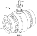
- Figure 3A shows a perspective view of the valve assembly 301
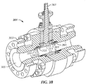
- Figure 3B shows perspective sectioned view of the valve assembly 301
- Figure 3C shows a cross-sectional view of the valve assembly 301
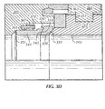
- Figure 3D shows a detailed cross-sectional view of a portion of the valve assembly 301
- Figure 3E shows a detailed cross-sectional schematic view of a portion of the valve assembly 301.
- the valve assembly 301 includes a housing 303, in which the housing 303 has a passage 305 formed therethrough.
- the passage 305 of the housing 303 may be formed about an axis 307 that extends through the housing 303.
- the passage 305 of the housing 303 may increase and/or decrease in diameter with respect to the axis 307 as the passage 305 extends through the housing 303 along the axis 307.
- the housing of the valve assembly may be formed as one monolithic structure, or, as shown in Figures 3A-3D , the housing 303 may be formed from portions attached to each other.
- the housing 303 may include a first portion 303a, a second portion 303b, and/or a third portion 303c.
- the housing of the valve assembly of the present disclosure may include more or less portions, as desired, and may be attached to each other, either permanently or temporarily, as desired.
- the valve assembly 301 includes a valve ball 311, in which the valve ball 311 has a through hole 313 formed therethrough. Particularly, as shown in Figures 3B and 3C , the through hole 313 of the valve ball 311 may be formed about an axis 315 that extends through the valve ball 311.
- the valve ball 311 is disposed within the housing 303 of the valve assembly 301 such that the valve ball 311 is rotatable with respect to the housing 303.
- the valve ball 311 is disposed within the housing 303 such that the valve ball 311 may be rotatable between an open position and a closed position with respect to the housing 303.
- the through hole 313 of the valve ball 311 may substantially align with the passage 305 of the housing 303, such as by having the axis 315 of the through hole 313 substantially align with the axis 307 of the passage 305.
- the valve assembly 301 will generally allow and enable fluid flow therethrough.
- the through hole 313 of the valve ball 311 may substantially misalign with the passage 305 of the housing 303, such as by having the axis 315 of the through hole 313 substantially misalign with the axis 307 of the passage 305.
- the valve assembly 301 will generally prohibit fluid flow therethrough.
- the valve assembly 301 includes a first seat 331 and a second seat 341.
- the first seat 331 and the second seat 341 are disposed within the housing 303 of the valve assembly 301, in which the first seat 331 may be disposed adjacent to the valve ball 311 and the second seat 341 may be disposed adjacent to the first seat 331.
- the first seat 331 may be disposed within the valve assembly 301 between the valve ball 311 and the second seat 341
- the second seat 341 may be disposed within the valve assembly 301 between the first seat 331 and the housing 303.
- first seat 331 and the second seat 341 may each include one or more sealing surfaces, in which the sealing surfaces may include an arcuate surface.
- the first seat 331 may include an arcuate surface 333
- the second seat 341 may include an arcuate surface 343.
- an "arcuate" surface may refer to a surface that has an arc or a curve formed thereon.
- the first seat may include an arcuate surface
- the second seat may include a corresponding sealing surface, such as a tapered and/or an angled surface, as compared to an arcuate surface.
- a corresponding sealing surface such as a tapered and/or an angled surface
- the arcuate surface 333 of the first seat 331 and/or the arcuate surface 343 of the second seat 341 may each be arched or curved with respect to the axis 307 extending through the housing 303.
- the arcuate surface 333 of the first seat 331 and the arcuate surface 343 of the second seat 341 may each have substantially the same arc or curve formed therein with respect to the axis 307 of the housing 303.
- the arcuate surface 333 of the first seat 331 and the arcuate surface 343 of the second seat 341 may each have substantially the same radius with respect to the axis 307 of the housing 303, such as within a tolerance of about 10 percent, at least.
- the arcuate surface 333 of the first seat 331 and the arcuate surface 343 of the second seat 341 may be spherical surfaces, thereby having a similar arc, radius, and/or curve to a sphere.
- having substantially the same radius may enable the arcuate surface 333 of the first seat 331 and the arcuate surface 343 of the second seat 341 to contact each other, and particularly have sealing contact therebetween.
- the arcuate surfaces 333 and 343 may develop sealing contact therebetween.
- first seat 331 may be formed such that the first seat 331 may have sealing contact with the valve ball 311.
- first seat 331 may have another sealing surface 335 formed thereon, in which the sealing surface 335 may be used to develop sealing engagement with the surface of the valve ball 311.
- the sealing surface 335 of the first seat 331 may be an arcuate surface, as shown, in which the surface of the valve ball 311 may correspond with the sealing surface 335 of the first seat 331.
- sealing surface of the first seat and the sealing surface of the valve ball in addition to any other sealing surfaces within the valve assembly, may have different shapes, sizes, and configurations, without departing from the scope of the present disclosure, such as by having, in one embodiment, an angled and/or tapered surface for the sealing surface of the first seat and/or the sealing surface of the valve ball. Accordingly, the present disclosure contemplates other arrangements, structures, and configurations for a valve assembly, as compared to those only shown in Figures 3A-3E .
- the second seat 341 may be formed such that the second seat 341 has sealing contact with the housing 303.
- the second seat 341 may form a seal between one of the sides of the second seat 341 and the housing 303.
- a groove 345 as shown in Figure 3B particularly, may also be formed with the second seat 341, in which a sealing member 347, such as a Grafoil® seal or other sealing member known in the art, may be disposed within the groove 345 of the second seat 341.
- the sealing member 347 may be disposed in the groove 345 on the arcuate surface 343 of the second seat 341 to provide an additional, or alternative, seal between the first seat 331 and the second seat 341.
- the valve assembly 301 may further include a biasing mechanism 351, in which the biasing mechanism 351 may be used to bias the first seat 331 and/or the second seat 341 towards the valve ball 311.
- the biasing mechanism 351 may be disposed within the housing 303 of the valve assembly 301, and, in one embodiment, may specifically be disposed between the second seat 341 and the housing 303 of the valve assembly 301. This arrangement may enable the biasing mechanism 351 to be positioned between the housing 303 of the valve assembly 301 and the second seat 341, thereby enabling the biasing mechanism 351 to push against the housing 303 and bias the first seat 331 and the second seat 341 towards the valve ball 311.
- the biasing mechanism 351 may be, for example, a Bellville washer, as shown.
- any other biasing mechanism may be used within the valve assembly, such a spring and/or an elastomeric member, without departing from the scope of the present disclosure.
- the biasing mechanism is shown as disposed between one of the seats and the housing in Figures 3B-3E .
- other arrangements may be used to bias one or more of the seats towards the valve ball in accordance with embodiments disclosed herein without departing from the scope of the present disclosure.
- the valve assembly 301 may include a stem 361.
- the stem 361 may extend through an opening 363 formed within the housing 303 of the valve assembly 301.
- the stem 361 may extend through the opening 363 to couple to the valve ball 311 of the valve assembly 301, in which the stem 361 may be used to rotate the valve ball 311, such as rotate the valve ball 311 between the open position and the closed position with respect to the housing 303.
- the valve ball 311 may have a recess 317 formed therein, in which the stem 361 may extend into and engage the recess 317 of the valve ball 311 to rotate the valve ball 311 between the open position and the closed position.
- the stem 361 may be used to engage and rotate the valve ball 311 from the exterior of the housing 303 as the valve ball 311 is disposed within the housing 303.
- the valve assembly 301 may also include one or more sealing members 365 disposed therein, such as to improve sealing capability of the valve assembly 301.
- a sealing member 365 may be disposed adjacent to the second seat 341 and between the housing 303 and the second seat 341. As such, the sealing member 365 may be used to seal, at least partially, about the second seat 341.
- a plate 367 such as a sealing gland, may be disposed adjacent to the one or more sealing members 365, in which one or more attachment members 371 may be used to attach the plate 367 to the housing 303.
- the attachment members 371 which may be bolts, as shown, or any other attachment member known in the art, may be used to attach the plate 367 to the housing 303, and further may be used to apply pressure to the sealing members 365 through the plate 367.
- the attachment members 371 may be selectively tightened, as desired, to apply pressure to the sealing members 365 using the plate 367, thereby adjusting the sealing properties of the sealing members 365, as desired.
- a sealing member in accordance with one or more embodiments disclosed herein, may be formed of and/or include any sealing material known in the art.
- a sealing member may be die formed, such as a die formed ring, and may be formed from or include Grafoil®, or any other sealing material known in the art.
- Grafoil® Grafoil®
- other sealing members may be included with and/or disposed within the valve assembly without departing from the scope of the present disclosure.
- one or more washers may be included within the valve assembly to improve the sealing capability of the valve assembly.
- one or more washers may be disposed adjacent to the sealing member 365, such as zero clearance washers, and one or more washers may be disposed adjacent to the attachment members 371, such as loaded washers.
- the first seat 331 includes the arcuate surface 333
- the second seat 341 includes the arcuate surface 343.
- the first seat 331 and the second seat 341 may be able to move with respect to each other within the housing 303.
- the second seat 341 may be able to move along the axis 307 extending through the housing 303, such as being able to move only along the axis 307 extending through the housing 303, and the first seat 331 may be able to precess with respect to the axis 307 extending through the housing 303.
- the movement of the first seat 331 may be decoupled from the movement of the second seat 341, in which the first seat 331 may be able to precess with respect to the second seat 341 and the housing 303 such that the first seat 331 may be able to change the orientation of an axis of the first seat 331.
- a valve ball within a valve assembly may shift such as to lose or compromise the sealing engagement between a seat within the valve assembly and the valve ball. This is shown particularly in Figure 2B .
- the first seat within the valve assembly of the present disclosure may be able to precess with respect to second seat and valve ball of the valve assembly, the first seat may be able to maintain sealing engagement with the valve ball, despite the valve ball moving and shifting within the valve assembly.
- the valve assembly 401 includes the first seat 431 disposed adjacent to the valve ball 411, in which the housing of the valve assembly 401 has the axis 407 extending therethrough and the first seat 431 has an axis 437 extending therethrough.
- the first seat may precess to maintain sealing engagement with the valve ball.
- the first seat 431 may precess with respect to the axis 407 of the housing such that the first seat 431 may maintain sealing engagement with the valve ball 411.
- the first seat 431 is shown as precessing by ⁇ degrees between the axis 407 of the housing and the axis 437 extending through the first seat 431. Accordingly, in one embodiment, the first seat may be able to precess up to about 5 degrees with respect to the axis extending through the housing. Further, in another embodiment, the first seat may be able to precess up to about 1 degree with respect to the axis extending through the housing.
- the present disclosure is not limited to the values and ranges discussed above. Further, though the movement between the valve ball 411 and the first seat 431 may be exaggerated and not drawn to scale in Figure 4 , this type of movement and shifting may demonstrate interaction and engagement between the valve ball 411 and the first seat 431.
- the first seat and the second seat may be able to work with each other and/or have coordinated movements together such that, as the valve ball moves within the valve assembly, the first seat and the second seat may be able to move in conjunction with each other such as to be able to properly sealingly engage with the valve ball of the valve assembly.
- the first seat and the second seat may need to move, such as by having the first seat precess and the second seat move axially with respect to an axis extending through the housing of the valve assembly.
- only the first seat or the second seat may need to move. Accordingly, the movement of the first seat and the second seat may correspond to the movement of the valve ball such that the valve assembly desirably forms sealing engagement therein.
- a stop shoulder may be included within the housing to limit the precess of the first seat with respect to other components within the valve assembly.
- a stop shoulder 339 may be included within the valve assembly 301, and particularly disposed upon and/or attached to the first seat 331 in this embodiment, such that the stop shoulder 339 is configured to limit the precession of the first seat 331 with respect to the second seat 341 and/or other components within the valve assembly 301.
- the stop shoulder 339 may be used to engage the second seat 341 to limit the precession of the first seat 331 with respect to the second seat 341. Further, the stop shoulder 339 may be used to keep the first seat 331 in a desired position relative to the valve ball 311. For example, the first seat 331 may move with the valve ball 311 with respect to the second seat 341. As such, the stop shoulder 339 may be used to prevent the first seat 331 from un-desired movement, such as by having the first seat 331 from over rotating with respect to the second seat 341 as the valve ball 311 rotates. Additionally, those having ordinary skill in the art will appreciate that other structures and arrangements may be used to limit the precession movement of the first seat without departing from the scope of the present disclosure.
- one or more components of the valve assembly may be mate lapped, such as by hand and/or by a machine process, to enhance the sealing contact between the components.
- the first seat 331 and the second seat 341 may be mate lapped together, and/or the first seat 331 and the valve ball 311 may be mate lapped together.
- the components of the valve assembly 301 that are mate lapped may develop a metal-to-metal seal for the sealing contact therebetween.
- mate lapping sealing surfaces of the valve assembly may enhance the metal-to-metal seals formed within the valve assembly.
- one or more components within the valve assembly may be coated, such as having a hard coating formed thereon or applied thereto.
- a hard coating formed thereon or applied thereto.
- at least a portion of the valve ball, housing, first seat, and/or second seat may have a hard coating disposed thereon. This hard coating may be used to increase strength, durability, and/or wear resistance of the components the hard coating is applied upon.
- one or more components of the valve assembly such as within one or more of the metal-to-metal seals, may have a hard coating applied thereto.
- a metal-to-metal seal may include a coating, such as a hard coating, carbide coating, or any other coating known in the art, and/or may include alternative materials disposed thereon and/or disposed therebetween one or more components of the present disclosure.
- a coating such as a hard coating, carbide coating, or any other coating known in the art, and/or may include alternative materials disposed thereon and/or disposed therebetween one or more components of the present disclosure.
- the present disclosure contemplates the use of multiple coatings and/or materials therein in accordance with one or more embodiments disclosed herein.
- the valve assembly 301 includes the first seat 331 and the second seat 341 disposed on one side of the valve ball 311 within the housing 303.
- one or more seats may also be disposed on another side of the valve ball 311 with respect to the first seat 331.
- a third seat 381 and/or a fourth seat 391 similar in structure and arrangement to the first seat 331 and the second seat 341, respectively, may be disposed on an opposite of the valve ball 311 with respect to the first seat 331.
- the valve ball 311 may be configured to form a metal-to-metal seal with the first seat 331, and during the other direction of fluid flow within the valve assembly 301, the valve ball 311 may be configured to form a metal-to-metal seal with the third seat 391.
- the valve ball 311 may be configured to form a metal-to-metal seal with the third seat 391.
- the biasing mechanism may be disposed within the housing in a partially compressed state.
- the biasing mechanism 351 may be partially compressed such that the biasing mechanism 351 may apply a biasing force against the first seat 331 and/or the second seat 341. As such, this may enable the first seat 331 to translate and apply the biasing force against the valve ball 311.
- valve assembly 501 is similar to the valve assembly 301 in Figures 3A-3E , however the valve assembly 501 in Figure 5 includes multiple ports and outlets, such as a 3-way valve assembly 501 as shown, as compared to the bi-directional valve assembly 301 shown in Figures 3A-3E .
- the valve assembly 501 may include a valve ball 511 and one or more passages 505 to have fluid received therein and/or directed out therethrough. Further, multiple seats may be disposed adjacent to the valve ball 511 on different sides of the valve ball 511 to provide sealing engagement therewith.
- valve assembly 501 one or more different sides of the valve ball 511, a first seat 531 and a second seat 541 with a biasing mechanism 551 may be included with the valve assembly 501, similar in structure and arrangement to the valve assembly 301.
- the present disclosure contemplates a valve assembly having one or more pairs of seats therein, in which one or more arcuate surfaces may be included within one or more of the pairs of seats within the valve assembly. Accordingly, those having ordinary skill in the art will appreciate that the present disclosure contemplates multiple arrangements, configurations, and embodiments for a valve assembly having at least a first seat and a second seat, in which at least one of the sealing surfaces of the first seat and the second seat includes an arcuate surface.
- Embodiments of the present disclosure may have one or more of the following advantages.
- First, embodiments disclosed herein may provide for a valve assembly that may be used to inhibit fluid flow in one or more directions, such as in the downstream direction and/or the upstream direction. This sealing capability of the valve assembly may increase the functionality and reliability of the assembly to seal in the upstream direction.
- embodiments disclosed herein may provide for a valve assembly that may be able to adjust and provide sealing capability despite shifting and/or movement of a valve ball within the valve assembly. As such, one or more of the seats within the valve assembly may be able to precess within the valve assembly to adjust and compensate for movement of the valve ball.
- embodiments in accordance with the present disclosure may be designed such as to replace one or more components of existing valve assemblies.
- an existing valve assembly having a valve body, a first seat, a valve ball, a second seat, and a biasing mechanism may have one or more components replaced.
- the seat and the biasing mechanism in such an embodiment may be replaced with a spring, a seat, and a second seat in accordance with embodiments of the present disclosure.
- this may enable existing valve assemblies to be modified such that the valve assembly may have bi-directional sealing capability and inhibit fluid flow in both the downstream and upstream directions.
Landscapes
- Engineering & Computer Science (AREA)
- General Engineering & Computer Science (AREA)
- Mechanical Engineering (AREA)
- Taps Or Cocks (AREA)
Abstract
Description
- Embodiments disclosed herein generally relate to methods and assemblies that include a valve ball used to start and stop fluid flow. More specifically, embodiments disclosed herein relate to a valve assembly having a valve ball with multiple moveable seats to seal against fluid flow from the upstream and/or the downstream direction.
- The use of ball valves to start and stop the flow of fluids is well known in the art. Ball valves typically include a valve ball that is located between two seats in the middle of a passage. The valve ball has a through hole, and can be rotated between two positions.
U.S. Patent No. 5,246,203, issued to McKnight et al . ("McKnight") discloses an oilfield valve that incorporates a ball valve mechanism. The mechanics of a typical ball valve mechanism are demonstrated in the McKnight patent. - In a first position, as demonstrated in
Figure 1A , the through hole of the valve ball will align with the passage of the pipe or drill string. This position will generally allow complete and undisrupted fluid flow through the passage. The valve ball may then be rotated from this position into a second position, as demonstrated inFigure 1B , to be misaligned with the passage of the pipe, thereby disrupting fluid flow. Each of the seats surrounding the valve ball, one upper seat and one lower seat, seal against the valve ball, not allowing flow between the valve ball and the seat. Thus, the valve ball, coupled with the two seats sealing against the valve ball, may stop fluid flow through the pipe passage when the valve ball is positioned in the closed position to misalign with the through hole passage by having the seats seal up against the valve ball. InFigure 1B , a seal is made between the seats, 101 and 102, and thevalve ball 105 to completely prohibit flow through the passage. The valve ball has the ability to seal against the seats to be effective against even the highest of pressures, allowing the arrangement to be used as a ball valve. - One issue with this type of ball valve arrangement is that when the
valve ball 105 is in the second position, blocking flow through the passage, as seen inFigure 1B , thevalve ball 105 may not be able to effectively seal against the fluid flow, such as both in the upstream and downstream direction. For example, debris comes between thevalve ball 105 and theseat 102, only sealing on thedownstream seat 101 may be achieved. In such an example, if a fluid force is applied from the downstream direction, the debris may cause the valve to be unable to effectively seal between thevalve ball 105 and theseat 102, thereby resulting in a leakage through the ball valve arrangement. - Further, because the
valve ball 105 is usually fixed in all directions, except for rotating between an open and closed position, theseats valve ball 105 to ensure proper sealing engagement between theseats valve ball 105. If thevalve ball 105 shifts in any direction, such as towards either side with respect to theseats seats valve ball 105. - For example,
Figures 2A and 2B show a valve assembly having aseat 201 and avalve ball 205 disposed adjacent to each other with respect to anaxis 200 of the valve assembly. InFigure 2A , theseat 201 and thevalve ball 205 are aligned with each other to ensure proper sealing engagement therebetween. However, inFigure 2B , thevalve ball 205 has shifted with respect to theseat 201 and theaxis 200 such that theseat 201 and thevalve ball 205 have lost proper sealing engagement therebetween. For example, as theseat 201 may only move along theaxis 200 with respect to thevalve ball 205, theseat 201 may not be able to move side-to-side and/or rotate with respect to thevalve ball 205, such as having theseat 201 move radially with respect to theaxis 200. As such, theseat 201 and thevalve ball 205 may lose proper sealing engagement therebetween. Though the movement between thevalve ball 205 and theseat 201 may be exaggerated and not drawn to scale inFigure 2B , this type of movement and shifting between thevalve ball 205 and theseat 201 may demonstrate how even minor movements may lead to a loss of proper sealing within a valve assembly, particularly within a valve assembly having metal-to-metal seals. - Accordingly, there exists a need to provide a ball valve assembly that may be able to identify and adjust for movements between one or more components within the valve assembly, particularly movement between one or more seats and the valve ball within the valve assembly, without compromising sealing integrity of the valve assembly.
- In one aspect, embodiments disclosed herein relate to a valve assembly. The valve assembly includes a housing having a passage formed therethrough, and a valve ball having a through hole and disposed in the housing, in which the valve ball is rotatable between an open position that has the through hole substantially aligned with the passage and a closed position that has the through hole substantially misaligned with the passage. The valve assembly further includes a first seat having a first sealing surface and disposed in the housing adjacent to the valve ball, and a second seat having a second sealing surface and disposed in the housing adjacent to the first seat such that the first sealing surface of the first seat is disposed adjacent to the second sealing surface of the second seat, in which at least one of the first sealing surface of the first seat and the second sealing surface of the second seat includes an arcuate surface.
- In one embodiment, the first seat is configured to precess with respect to an axis extending through the housing, and the second seat is configured to move along the axis extending through the housing.
- In one embodiment, the first seat is configured to precess up to about 5 degrees with respect to the axis extending through the housing.
- In one embodiment, the first seat is configured to precess up to about 1 degree with respect to the axis extending through the housing.
- In one embodiment, the valve assembly further comprises a stop shoulder disposed within the housing such that the stop shoulder is configured to limit the precess of the first seat with respect to the axis extending through the housing.
- In one embodiment, the stop shoulder is attached to the first seat.
- In one embodiment, the valve assembly further comprises a sealing element disposed between the first sealing surface of the first seat and the second sealing surface of the second seat.
- In one embodiment, the valve assembly further comprises a sealing element disposed between the second seat and the housing.
- In one embodiment, the valve ball and the first seat are mate-lapped together and are configured to form a seal therebetween, and wherein the first seat and the second seat are mate-lapped together and are configured to form another seal therebetween
- In another aspect, embodiments disclosed herein relate to another valve assembly. The valve assembly includes a housing having a passage formed therethrough about a first axis, and a valve ball having a through hole formed therethrough about a second axis, in which the valve ball is configured to rotate between an open position such that the first axis of the housing is substantially aligned with the second axis of the valve ball and a closed position such that the first axis of the housing is substantially misaligned with the second axis of the valve ball. The valve assembly further includes a stem extending through an opening formed in the housing and coupled to the valve ball such that the stem is configured to rotate the valve ball between the open position and the closed position, a first seat having a first sealing surface and disposed in the housing adjacent to the valve ball on one side of the valve ball, and a second seat having a second sealing surface and disposed in the housing adjacent to the first seat such that the first sealing surface of the first seat is disposed adjacent to the second sealing surface of the second seat, in which at least one of the first sealing surface of the first seat and the second sealing surface of the second seat includes an arcuate surface.
- In one embodiment, the first sealing surface of the first seat comprises a first arcuate surface, and wherein the second sealing surface of the second seat comprises a second arcuate surface.
- In one embodiment, the at least one of the first sealing surface of the first seat and the second sealing surface of the second seat comprise a spherical surface.
- In one embodiment, another of the first sealing surface of the first seat and the second sealing surface of the second seat comprises a tapered surface.
- In one embodiment, the valve assembly further comprises a biasing mechanism disposed, at least partially, between the housing and the second seat, wherein the biasing mechanism biases at least one of the first seat and the second seat towards the valve ball.
- In one embodiment, the valve assembly further comprises a third seat, wherein the third seat is disposed on another side of the valve ball with respect to the first seat, and wherein, during one direction of fluid flow, the valve ball is configured to form a metal-to-metal seal with the first seat, and during another direction of fluid flow, the valve ball is configured to form a metal-to-metal seal with the third seat.
- In one embodiment, the first seat is configured to precess with respect to the first axis extending through the housing, and wherein the second seat is configured to move along the first axis extending through the housing.
- In yet another aspect, embodiments disclosed herein relate to a method to manufacture a valve assembly. The method includes disposing a first seat having a first sealing surface in a housing, the housing having a passage formed therethrough, and disposing a second seat having a second sealing surface in the housing adjacent to the first seat such that the first sealing surface of the first seat is adjacent to the second sealing surface of the second seat, in which at least one of the first sealing surface of the first seat and the second sealing surface of the second seat includes an arcuate surface. The method further includes disposing a valve ball having a through hole formed therein in the housing adjacent to the first seat such that the valve ball is rotatable within the housing between an open position that has the through hole substantially aligned with the passage and a closed position that has the through hole substantially misaligned with the passage.
- In one embodiment, the at least one of the first sealing surface of the first seat and the second sealing surface of the second seat comprise a spherical surface.
- In one embodiment, another of the first sealing surface of the first seat and the second sealing surface of the second seat comprises a tapered surface.
- Other aspects and advantages of the invention will be apparent from the following description and the appended claims.
-
Figures 1A and 1B show cross-sectional views of a ball valve assembly according to the prior art. -
Figures 2A and 2B show cross-sectional views of a ball valve assembly according to the prior art. -
Figures 3A-3E show multiple views of a valve assembly in accordance with embodiments disclosed herein. -
Figure 4 shows a cross-sectional view of a valve assembly in accordance with embodiments disclosed herein. -
Figure 5 shows a perspective view of a valve assembly in accordance with embodiments disclosed herein. - Embodiments of the present disclosure will now be described in detail with reference to the accompanying Figures. Like elements in the various figures may be denoted by like reference numerals for consistency. Further, in the following detailed description of embodiments of the present disclosure, numerous specific details are set forth in order to provide a more thorough understanding of the claimed subject matter. However, it will be apparent to one of ordinary skill in the art that the embodiments disclosed herein may be practiced without these specific details. In other instances, well-known features have not been described in detail to avoid unnecessarily complicating the description.
- In accordance with various aspects disclosed herein, embodiments disclosed herein generally relate to a valve assembly, and particularly a ball valve assembly, that is used to start and stop fluid flow therethrough. The valve assembly may include a housing having a passage formed therethrough, in which the passage may be formed about a first axis. The valve assembly may further include a valve ball having a through hole formed therethrough, in which the through hole may be formed about a second axis. The valve ball is disposed within the housing such that the valve ball is rotatable between an open position and a closed position within the housing. In the open position, the through hole of the valve ball may align with the passage of the housing, such as by having the second axis of the through hole substantially align with the first axis of the passage, thereby generally enabling fluid flow therethrough. In the closed position, the through hole of the valve ball may substantially misalign with the passage of the housing, such as by having the second axis of the through hole substantially misalign with the first axis of the passage, thereby generally prohibiting fluid flow therethrough.
- Further, the valve assembly includes a first seat having a first sealing surface, in which the first seat is disposed within the housing, and includes a second seat having a second sealing surface, in which the second seat is also disposed in the housing. The first seat and the second seat are disposed within the housing such that the first sealing surface of the first seat is disposed adjacent to the second sealing surface of the second seat. As such, at least one of the first sealing surface of the first seat and the second sealing surface of the second seat is and/or includes an arcuate surface. For example, the first seat and/or the second seat may include an arcuate surface as a sealing surface. In an embodiment in which one of the sealing surfaces of the first seat and the second seat comprises an arcuate surface, the other of the first sealing surface and the second sealing surface may be and/or include a tapered surface, such as by having an arcuate surface on the first seat and a tapered surface on the second seat.
- Furthermore, the first seat is disposed adjacent to the valve ball, and the first seat and/or the second seat may be biased towards the valve ball. As such, the first seat and/or the second seat may be biased towards the valve ball, such as by using a biasing mechanism. In one embodiment, the biasing mechanism may be disposed, at least partially, between the second seat and the housing.
- The valve assembly may further include a stem, in which the stem extends through an opening formed within the housing. The stem may then be coupled to the valve ball such that the stem may be configured to rotate the valve ball between the open position and the closed position within the housing. The valve assembly may also include one or more additional seats, such as by having a third seat (and/or a fourth seat) disposed on another side of the valve ball with respect to the first seat. As such, in one embodiment, during one direction of fluid flow against the valve ball, the valve ball may be configured to form a metal-to-metal seal with the first seat, and during the other direction of fluid flow against the valve ball, the valve ball may be configured to form a metal-to-metal seal with the third seat.
- Referring now to
Figures 3A-3E , multiple views of avalve assembly 301 in accordance with embodiments disclosed herein are shown. Specifically,Figure 3A shows a perspective view of thevalve assembly 301,Figure 3B shows perspective sectioned view of thevalve assembly 301,Figure 3C shows a cross-sectional view of thevalve assembly 301,Figure 3D shows a detailed cross-sectional view of a portion of thevalve assembly 301, andFigure 3E shows a detailed cross-sectional schematic view of a portion of thevalve assembly 301. - As shown, the
valve assembly 301 includes ahousing 303, in which thehousing 303 has apassage 305 formed therethrough. Particularly, as shown inFigure 3C , thepassage 305 of thehousing 303 may be formed about anaxis 307 that extends through thehousing 303. As such, and as shown in this embodiment, thepassage 305 of thehousing 303 may increase and/or decrease in diameter with respect to theaxis 307 as thepassage 305 extends through thehousing 303 along theaxis 307. - One having ordinary skill in the art will appreciate that, in accordance with one or more embodiments disclosed herein, the housing of the valve assembly may be formed as one monolithic structure, or, as shown in
Figures 3A-3D , thehousing 303 may be formed from portions attached to each other. For example, as shown particularly inFigure 3C , thehousing 303 may include afirst portion 303a, asecond portion 303b, and/or athird portion 303c. Those having ordinary skill in the art will appreciate that the housing of the valve assembly of the present disclosure may include more or less portions, as desired, and may be attached to each other, either permanently or temporarily, as desired. - Further, the
valve assembly 301 includes avalve ball 311, in which thevalve ball 311 has a throughhole 313 formed therethrough. Particularly, as shown inFigures 3B and3C , the throughhole 313 of thevalve ball 311 may be formed about anaxis 315 that extends through thevalve ball 311. As such, thevalve ball 311 is disposed within thehousing 303 of thevalve assembly 301 such that thevalve ball 311 is rotatable with respect to thehousing 303. Specifically, thevalve ball 311 is disposed within thehousing 303 such that thevalve ball 311 may be rotatable between an open position and a closed position with respect to thehousing 303. - In the open position, as shown in
Figures 3B-3E , the throughhole 313 of thevalve ball 311 may substantially align with thepassage 305 of thehousing 303, such as by having theaxis 315 of the throughhole 313 substantially align with theaxis 307 of thepassage 305. As such, when thevalve ball 311 is in the open position, thevalve assembly 301 will generally allow and enable fluid flow therethrough. In the closed position, the throughhole 313 of thevalve ball 311 may substantially misalign with thepassage 305 of thehousing 303, such as by having theaxis 315 of the throughhole 313 substantially misalign with theaxis 307 of thepassage 305. As such, when thevalve ball 311 is in the closed position, thevalve assembly 301 will generally prohibit fluid flow therethrough. - Referring still to
Figures 3A-3E , thevalve assembly 301 includes afirst seat 331 and asecond seat 341. As shown, thefirst seat 331 and thesecond seat 341 are disposed within thehousing 303 of thevalve assembly 301, in which thefirst seat 331 may be disposed adjacent to thevalve ball 311 and thesecond seat 341 may be disposed adjacent to thefirst seat 331. Particularly, thefirst seat 331 may be disposed within thevalve assembly 301 between thevalve ball 311 and thesecond seat 341, and thesecond seat 341 may be disposed within thevalve assembly 301 between thefirst seat 331 and thehousing 303. - As shown, the
first seat 331 and thesecond seat 341 may each include one or more sealing surfaces, in which the sealing surfaces may include an arcuate surface. For example, thefirst seat 331 may include anarcuate surface 333, and thesecond seat 341 may include anarcuate surface 343. As used herein, an "arcuate" surface may refer to a surface that has an arc or a curve formed thereon. One having ordinary skill in the art will appreciate that, thoughFigures 3A-3E show thefirst seat 331 and thesecond seat 341 each includingarcuate surfaces - Referring still to
Figures 3A-3E , thearcuate surface 333 of thefirst seat 331 and/or thearcuate surface 343 of thesecond seat 341 may each be arched or curved with respect to theaxis 307 extending through thehousing 303. Thearcuate surface 333 of thefirst seat 331 and thearcuate surface 343 of thesecond seat 341 may each have substantially the same arc or curve formed therein with respect to theaxis 307 of thehousing 303. For example, thearcuate surface 333 of thefirst seat 331 and thearcuate surface 343 of thesecond seat 341 may each have substantially the same radius with respect to theaxis 307 of thehousing 303, such as within a tolerance of about 10 percent, at least. Particularly, in one embodiment, thearcuate surface 333 of thefirst seat 331 and thearcuate surface 343 of thesecond seat 341 may be spherical surfaces, thereby having a similar arc, radius, and/or curve to a sphere. As such, having substantially the same radius may enable thearcuate surface 333 of thefirst seat 331 and thearcuate surface 343 of thesecond seat 341 to contact each other, and particularly have sealing contact therebetween. For example, as thearcuate surface 333 of thefirst seat 331 and thearcuate surface 343 of thesecond seat 341 come into contact and may have substantially the same radius with respect to theaxis 307 of thehousing 303, thearcuate surfaces - Further, the
first seat 331 may be formed such that thefirst seat 331 may have sealing contact with thevalve ball 311. For example, thefirst seat 331 may have another sealingsurface 335 formed thereon, in which thesealing surface 335 may be used to develop sealing engagement with the surface of thevalve ball 311. In one embodiment, the sealingsurface 335 of thefirst seat 331 may be an arcuate surface, as shown, in which the surface of thevalve ball 311 may correspond with the sealingsurface 335 of thefirst seat 331. Those having ordinary skill in the art, however, will appreciate that the sealing surface of the first seat and the sealing surface of the valve ball, in addition to any other sealing surfaces within the valve assembly, may have different shapes, sizes, and configurations, without departing from the scope of the present disclosure, such as by having, in one embodiment, an angled and/or tapered surface for the sealing surface of the first seat and/or the sealing surface of the valve ball. Accordingly, the present disclosure contemplates other arrangements, structures, and configurations for a valve assembly, as compared to those only shown inFigures 3A-3E . - Furthermore, the
second seat 341 may be formed such that thesecond seat 341 has sealing contact with thehousing 303. For example, thesecond seat 341 may form a seal between one of the sides of thesecond seat 341 and thehousing 303. Agroove 345, as shown inFigure 3B particularly, may also be formed with thesecond seat 341, in which a sealingmember 347, such as a Grafoil® seal or other sealing member known in the art, may be disposed within thegroove 345 of thesecond seat 341. As such, in the embodiment shown inFigure 3E , the sealingmember 347 may be disposed in thegroove 345 on thearcuate surface 343 of thesecond seat 341 to provide an additional, or alternative, seal between thefirst seat 331 and thesecond seat 341. - The
valve assembly 301 may further include abiasing mechanism 351, in which thebiasing mechanism 351 may be used to bias thefirst seat 331 and/or thesecond seat 341 towards thevalve ball 311. Thebiasing mechanism 351 may be disposed within thehousing 303 of thevalve assembly 301, and, in one embodiment, may specifically be disposed between thesecond seat 341 and thehousing 303 of thevalve assembly 301. This arrangement may enable thebiasing mechanism 351 to be positioned between thehousing 303 of thevalve assembly 301 and thesecond seat 341, thereby enabling thebiasing mechanism 351 to push against thehousing 303 and bias thefirst seat 331 and thesecond seat 341 towards thevalve ball 311. Thebiasing mechanism 351 may be, for example, a Bellville washer, as shown. However, those having ordinary skill in the art will appreciate that any other biasing mechanism may be used within the valve assembly, such a spring and/or an elastomeric member, without departing from the scope of the present disclosure. Further, the biasing mechanism is shown as disposed between one of the seats and the housing inFigures 3B-3E . However, those having ordinary skill in the art will appreciate that other arrangements may be used to bias one or more of the seats towards the valve ball in accordance with embodiments disclosed herein without departing from the scope of the present disclosure. - Referring still to
Figures 3A-3E , thevalve assembly 301 may include astem 361. As shown, thestem 361 may extend through anopening 363 formed within thehousing 303 of thevalve assembly 301. Particularly, thestem 361 may extend through theopening 363 to couple to thevalve ball 311 of thevalve assembly 301, in which thestem 361 may be used to rotate thevalve ball 311, such as rotate thevalve ball 311 between the open position and the closed position with respect to thehousing 303. For example, as shown, thevalve ball 311 may have arecess 317 formed therein, in which thestem 361 may extend into and engage therecess 317 of thevalve ball 311 to rotate thevalve ball 311 between the open position and the closed position. As such, thestem 361 may be used to engage and rotate thevalve ball 311 from the exterior of thehousing 303 as thevalve ball 311 is disposed within thehousing 303. - The
valve assembly 301 may also include one ormore sealing members 365 disposed therein, such as to improve sealing capability of thevalve assembly 301. For example, as shown inFigures 3A-3E , a sealingmember 365 may be disposed adjacent to thesecond seat 341 and between thehousing 303 and thesecond seat 341. As such, the sealingmember 365 may be used to seal, at least partially, about thesecond seat 341. - A
plate 367, such as a sealing gland, may be disposed adjacent to the one ormore sealing members 365, in which one ormore attachment members 371 may be used to attach theplate 367 to thehousing 303. For example, as shown inFigures 3D and3E , theattachment members 371, which may be bolts, as shown, or any other attachment member known in the art, may be used to attach theplate 367 to thehousing 303, and further may be used to apply pressure to the sealingmembers 365 through theplate 367. Particularly, as shown, theattachment members 371 may be selectively tightened, as desired, to apply pressure to the sealingmembers 365 using theplate 367, thereby adjusting the sealing properties of the sealingmembers 365, as desired. - One having ordinary skill in the art will appreciate that a sealing member, in accordance with one or more embodiments disclosed herein, may be formed of and/or include any sealing material known in the art. For example, in one embodiment, a sealing member may be die formed, such as a die formed ring, and may be formed from or include Grafoil®, or any other sealing material known in the art. Further, those having ordinary skill in the art will appreciate that in addition, or in alternative, to the sealing
member 365 and the sealingmember 345, other sealing members may be included with and/or disposed within the valve assembly without departing from the scope of the present disclosure. Furthermore, to improve the sealing of one or more of the sealing members within the valve assembly, one or more washers, or similar mechanisms in placement and/or function, may be included within the valve assembly to improve the sealing capability of the valve assembly. For example, inFigure 3E , one or more washers may be disposed adjacent to the sealingmember 365, such as zero clearance washers, and one or more washers may be disposed adjacent to theattachment members 371, such as loaded washers. - As discussed above, the
first seat 331 includes thearcuate surface 333, and thesecond seat 341 includes thearcuate surface 343. As such, because of the shape and positioning of thearcuate surfaces first seat 331 and thesecond seat 341 may be able to move with respect to each other within thehousing 303. For example, with the arrangement of theseats second seat 341 may be able to move along theaxis 307 extending through thehousing 303, such as being able to move only along theaxis 307 extending through thehousing 303, and thefirst seat 331 may be able to precess with respect to theaxis 307 extending through thehousing 303. Particularly, the movement of thefirst seat 331 may be decoupled from the movement of thesecond seat 341, in which thefirst seat 331 may be able to precess with respect to thesecond seat 341 and thehousing 303 such that thefirst seat 331 may be able to change the orientation of an axis of thefirst seat 331. - As previously discussed, particularly with respect to
Figures 2A and 2B , a valve ball within a valve assembly may shift such as to lose or compromise the sealing engagement between a seat within the valve assembly and the valve ball. This is shown particularly inFigure 2B . However, in accordance with one or more embodiments disclosed herein, because the first seat within the valve assembly of the present disclosure may be able to precess with respect to second seat and valve ball of the valve assembly, the first seat may be able to maintain sealing engagement with the valve ball, despite the valve ball moving and shifting within the valve assembly. - Referring now to
Figure 4 , a cross-sectional view of avalve assembly 401 in accordance with embodiments disclosed herein is shown. Thevalve assembly 401 includes thefirst seat 431 disposed adjacent to thevalve ball 411, in which the housing of thevalve assembly 401 has theaxis 407 extending therethrough and thefirst seat 431 has anaxis 437 extending therethrough. As mentioned above, in accordance with embodiments disclosed herein, when the valve ball shifts within the valve assembly, the first seat may precess to maintain sealing engagement with the valve ball. As such, and as shown inFigure 4 , thefirst seat 431 may precess with respect to theaxis 407 of the housing such that thefirst seat 431 may maintain sealing engagement with thevalve ball 411. - In
Figure 4 , thefirst seat 431 is shown as precessing by α degrees between theaxis 407 of the housing and theaxis 437 extending through thefirst seat 431. Accordingly, in one embodiment, the first seat may be able to precess up to about 5 degrees with respect to the axis extending through the housing. Further, in another embodiment, the first seat may be able to precess up to about 1 degree with respect to the axis extending through the housing. However, those having ordinary skill in the art will appreciate that the present disclosure is not limited to the values and ranges discussed above. Further, though the movement between thevalve ball 411 and thefirst seat 431 may be exaggerated and not drawn to scale inFigure 4 , this type of movement and shifting may demonstrate interaction and engagement between thevalve ball 411 and thefirst seat 431. - As such, in accordance with one or more embodiments disclosed herein, the first seat and the second seat may be able to work with each other and/or have coordinated movements together such that, as the valve ball moves within the valve assembly, the first seat and the second seat may be able to move in conjunction with each other such as to be able to properly sealingly engage with the valve ball of the valve assembly. In one embodiment, the first seat and the second seat may need to move, such as by having the first seat precess and the second seat move axially with respect to an axis extending through the housing of the valve assembly. In another embodiment, only the first seat or the second seat may need to move. Accordingly, the movement of the first seat and the second seat may correspond to the movement of the valve ball such that the valve assembly desirably forms sealing engagement therein.
- Further, in accordance with one or more embodiments disclosed herein, because the first seat may be able to precess with respect to the housing and the second seat of the valve assembly, a stop shoulder may be included within the housing to limit the precess of the first seat with respect to other components within the valve assembly. For example, as shown in
Figures 3D and3E , astop shoulder 339 may be included within thevalve assembly 301, and particularly disposed upon and/or attached to thefirst seat 331 in this embodiment, such that thestop shoulder 339 is configured to limit the precession of thefirst seat 331 with respect to thesecond seat 341 and/or other components within thevalve assembly 301. In this embodiment, thestop shoulder 339 may be used to engage thesecond seat 341 to limit the precession of thefirst seat 331 with respect to thesecond seat 341. Further, thestop shoulder 339 may be used to keep thefirst seat 331 in a desired position relative to thevalve ball 311. For example, thefirst seat 331 may move with thevalve ball 311 with respect to thesecond seat 341. As such, thestop shoulder 339 may be used to prevent thefirst seat 331 from un-desired movement, such as by having thefirst seat 331 from over rotating with respect to thesecond seat 341 as thevalve ball 311 rotates. Additionally, those having ordinary skill in the art will appreciate that other structures and arrangements may be used to limit the precession movement of the first seat without departing from the scope of the present disclosure. - To further develop and improve the sealing contact and capabilities of a valve assembly in accordance with one or more embodiments disclosed herein, one or more components of the valve assembly may be mate lapped, such as by hand and/or by a machine process, to enhance the sealing contact between the components. For example, The
first seat 331 and thesecond seat 341 may be mate lapped together, and/or thefirst seat 331 and thevalve ball 311 may be mate lapped together. The components of thevalve assembly 301 that are mate lapped may develop a metal-to-metal seal for the sealing contact therebetween. As such, if desired, mate lapping sealing surfaces of the valve assembly may enhance the metal-to-metal seals formed within the valve assembly. - Further, one or more components within the valve assembly may be coated, such as having a hard coating formed thereon or applied thereto. For example, at least a portion of the valve ball, housing, first seat, and/or second seat may have a hard coating disposed thereon. This hard coating may be used to increase strength, durability, and/or wear resistance of the components the hard coating is applied upon. As such, one or more components of the valve assembly, such as within one or more of the metal-to-metal seals, may have a hard coating applied thereto.
- Further, in accordance with one or more embodiments of the present disclosure, a metal-to-metal seal may include a coating, such as a hard coating, carbide coating, or any other coating known in the art, and/or may include alternative materials disposed thereon and/or disposed therebetween one or more components of the present disclosure. As such, the present disclosure contemplates the use of multiple coatings and/or materials therein in accordance with one or more embodiments disclosed herein.
- Referring still to
Figures 3A-3E , thevalve assembly 301 includes thefirst seat 331 and thesecond seat 341 disposed on one side of thevalve ball 311 within thehousing 303. As such, to improve the sealing capability and utility of thevalve assembly 301, one or more seats may also be disposed on another side of thevalve ball 311 with respect to thefirst seat 331. For example, as shown inFigures 3B and3C , particularly, athird seat 381 and/or afourth seat 391, similar in structure and arrangement to thefirst seat 331 and thesecond seat 341, respectively, may be disposed on an opposite of thevalve ball 311 with respect to thefirst seat 331. As such, in one embodiment, during one direction of fluid flow within thevalve assembly 301, thevalve ball 311 may be configured to form a metal-to-metal seal with thefirst seat 331, and during the other direction of fluid flow within thevalve assembly 301, thevalve ball 311 may be configured to form a metal-to-metal seal with thethird seat 391. Those having ordinary skill in the art, however, will appreciate that other arrangements and/or designs for the seats may be used within the valve assembly without departing from the scope of the present disclosure. - In embodiments in which the valve assembly includes a biasing mechanism, such as a Bellville washer, the biasing mechanism may be disposed within the housing in a partially compressed state. For example, with reference to
Figures 3B-3E , thebiasing mechanism 351 may be partially compressed such that thebiasing mechanism 351 may apply a biasing force against thefirst seat 331 and/or thesecond seat 341. As such, this may enable thefirst seat 331 to translate and apply the biasing force against thevalve ball 311. - Referring now to
Figure 5 , a perspective view of avalve assembly 501 in accordance with one or more embodiments disclosed herein is shown. Thevalve assembly 501 is similar to thevalve assembly 301 inFigures 3A-3E , however thevalve assembly 501 inFigure 5 includes multiple ports and outlets, such as a 3-way valve assembly 501 as shown, as compared to thebi-directional valve assembly 301 shown inFigures 3A-3E . InFigure 5 , thevalve assembly 501 may include avalve ball 511 and one ormore passages 505 to have fluid received therein and/or directed out therethrough. Further, multiple seats may be disposed adjacent to thevalve ball 511 on different sides of thevalve ball 511 to provide sealing engagement therewith. In this embodiment, one or more different sides of thevalve ball 511, afirst seat 531 and asecond seat 541 with abiasing mechanism 551 may be included with thevalve assembly 501, similar in structure and arrangement to thevalve assembly 301. As such, the present disclosure contemplates a valve assembly having one or more pairs of seats therein, in which one or more arcuate surfaces may be included within one or more of the pairs of seats within the valve assembly. Accordingly, those having ordinary skill in the art will appreciate that the present disclosure contemplates multiple arrangements, configurations, and embodiments for a valve assembly having at least a first seat and a second seat, in which at least one of the sealing surfaces of the first seat and the second seat includes an arcuate surface. - Embodiments of the present disclosure may have one or more of the following advantages. First, embodiments disclosed herein may provide for a valve assembly that may be used to inhibit fluid flow in one or more directions, such as in the downstream direction and/or the upstream direction. This sealing capability of the valve assembly may increase the functionality and reliability of the assembly to seal in the upstream direction. Next, embodiments disclosed herein may provide for a valve assembly that may be able to adjust and provide sealing capability despite shifting and/or movement of a valve ball within the valve assembly. As such, one or more of the seats within the valve assembly may be able to precess within the valve assembly to adjust and compensate for movement of the valve ball.
- Further, embodiments in accordance with the present disclosure may be designed such as to replace one or more components of existing valve assemblies. For example, an existing valve assembly having a valve body, a first seat, a valve ball, a second seat, and a biasing mechanism may have one or more components replaced. Particularly, the seat and the biasing mechanism in such an embodiment may be replaced with a spring, a seat, and a second seat in accordance with embodiments of the present disclosure. As such, this may enable existing valve assemblies to be modified such that the valve assembly may have bi-directional sealing capability and inhibit fluid flow in both the downstream and upstream directions.
- While the present disclosure has been described with respect to a limited number of embodiments, those skilled in the art, having benefit of this disclosure, will appreciate that other embodiments may be devised.
Claims (15)
- A valve assembly (301, 401, 501) comprising:a housing (303) having a passage (305, 505) formed therethrough;a valve ball (311, 411, 511) having a through hole (313) and disposed in the housing (303), wherein the valve ball (311, 411, 511) is rotatable between an open position that has the through hole (313) substantially aligned with the passage (305, 505) and a closed position that has the through hole (313) substantially misaligned with the passage (305, 505);a first seat (331, 431, 531) having a first sealing surface and disposed in the housing (303) adjacent to the valve ball (311, 411, 511); anda second seat (341, 541) having a second sealing surface and disposed in the housing (303) adjacent to the first seat (331, 431, 531) such that the first sealing surface of the first seat (331, 431, 531) is disposed adjacent to the second sealing surface of the second seat (341, 541);wherein at least one of the first sealing surface of the first seat (331, 431, 531) and the second sealing surface of the second seat (341, 541) comprises an arcuate surface (333,343).
- The valve assembly (301, 401, 501) of claim 1, wherein the first sealing surface of the first seat (331, 431, 531) comprises a first arcuate surface (333), and wherein the second sealing surface of the second seat (341, 541) comprises a second arcuate surface (343).
- The valve assembly (301, 401, 501) of claim 1, wherein the at least one of the first sealing surface of the first seat (331, 431, 531) and the second sealing surface of the second seat (341, 541) comprise a spherical surface.
- The valve assembly (301, 401, 501) of claim 1, wherein another of the first sealing surface of the first seat (331, 431, 531) and the second sealing surface of the second seat (341, 541) comprises a tapered surface.
- The valve assembly (301, 401, 501) of any of the preceding claims, wherein at least one of the first seat (331, 431, 531) and the second seat (341, 541) is biased towards the valve ball (311, 411, 511).
- The valve assembly (301, 401, 501) of claim 5, further comprising a biasing mechanism (351, 551) disposed, at least partially, between the housing (303) and the second seat (341, 541), wherein the biasing mechanism (351, 551) biases the at least one of the first seat (331, 431, 531) and the second seat (341, 541) towards the valve ball (311, 411, 511).
- The valve assembly (301, 401, 501) of claim 6, wherein the biasing mechanism (351, 551) comprises a Bellville washer.
- The valve assembly (301, 401, 501) of any of the preceding claims, wherein the first seat (331, 431, 531) is configured to precess with respect to an axis (307, 407) extending through the housing (303), and wherein the second seat (341, 541) is configured to move along the axis (307, 407) extending through the housing (303).
- The valve assembly (301, 401, 501) of claim 8, further comprising a stop shoulder (339) disposed within the housing (303) such that the stop shoulder (339) is configured to limit the precess of the first seat (331, 431, 531) with respect to the axis (307, 407) extending through the housing.
- The valve assembly (301, 401, 501) of any of the preceding claims, further comprising:a third seat (381), wherein the third seat (381) is disposed on another side of the valve ball (311, 411, 511) with respect to the first seat (331, 431, 531),wherein, during one direction of fluid flow, the valve ball (311, 411, 511) is configured to form a metal-to-metal seal with the first seat (331, 431, 531), and during another direction of fluid flow, the valve ball (311, 411, 511) is configured to form a metal-to-metal seal with the third seat (381).
- A method to manufacture a valve assembly (301, 401, 501), the method comprising:disposing a first seat (331, 431, 531) having a first sealing surface in a housing (303), the housing (303) having a passage (305, 505) formed therethrough;disposing a second seat (341, 541) having a second sealing surface in the housing (303) adjacent to the first seat (331, 431, 531) such that the first sealing surface of the first seat (331, 431, 531) is adjacent to the second sealing surface of the second seat (341, 541), wherein at least one of the first sealing surface of the first seat (331, 431, 531) and the second sealing surface of the second seat (341, 541) comprises an arcuate surface (333, 343); anddisposing a valve ball (311, 411, 511) having a through hole (313) formed therein in the housing (303) adjacent to the first seat (331, 431, 531) such that the valve ball (311, 411, 511) is rotatable within the housing (303) between an open position that has the through hole (313) substantially aligned with the passage (305, 505) and a closed position that has the through hole (313) substantially misaligned with the passage (305,505).
- The method of claim 11, further comprising:disposing a biasing mechanism (351, 551), at least partially, between the housing (303) and the second seat (341, 541) such that the biasing mechanism (351, 551) is configured to bias at least one of the first seat (331, 431, 531) and the second seat (341, 541) towards the valve ball (311, 411, 511);disposing a stem (361) through an opening (363) formed in the housing (303) and coupling the stem (361) to the valve ball (311, 411, 511) such that the stem (361) is configured to rotate the valve ball (311, 411, 511) between the open position and the closed position; anddisposing a third seat (361) on another side of the valve ball (311, 411, 511) with respect to the first seat (331, 431, 531).
- The method of claim 12, wherein, during one direction of fluid flow, the valve ball (311, 411, 511) is configured to form a metal-to-metal seal with the first seat (331, 431, 531), and during another direction of fluid flow, the valve ball (311, 411, 511) is configured to form a metal-to-metal seal with the third seat (381).
- The method of any of claims 11 to 13, wherein the first seat (331, 431, 531) is configured to precess with respect to the first axis (307, 407) extending through the housing, and wherein the second seat (341, 541) is configured to move along the first axis (307, 407) extending through the housing.
- The method of any of claims 11 to 14, wherein the first sealing surface of the first seat (331, 431, 531) comprises a first arcuate surface (333), and wherein the second sealing surface of the second seat (341, 541) comprises a second arcuate surface (343).
Applications Claiming Priority (1)
| Application Number | Priority Date | Filing Date | Title |
|---|---|---|---|
| US13/034,325 US8646752B2 (en) | 2011-02-24 | 2011-02-24 | Ball valve having multiple moveable seats |
Publications (2)
| Publication Number | Publication Date |
|---|---|
| EP2492552A1 true EP2492552A1 (en) | 2012-08-29 |
| EP2492552B1 EP2492552B1 (en) | 2016-01-20 |
Family
ID=45571447
Family Applications (1)
| Application Number | Title | Priority Date | Filing Date |
|---|---|---|---|
| EP12154842.4A Active EP2492552B1 (en) | 2011-02-24 | 2012-02-10 | Ball valve having multiple moveable seats |
Country Status (2)
| Country | Link |
|---|---|
| US (2) | US8646752B2 (en) |
| EP (1) | EP2492552B1 (en) |
Cited By (2)
| Publication number | Priority date | Publication date | Assignee | Title |
|---|---|---|---|---|
| CN105805343A (en) * | 2016-06-01 | 2016-07-27 | 中玉阀门配件苏州有限公司 | Ball valve seat |
| EP4286494A3 (en) * | 2018-05-18 | 2024-02-21 | Mogas Industries, Inc. | Multiport valve |
Families Citing this family (9)
| Publication number | Priority date | Publication date | Assignee | Title |
|---|---|---|---|---|
| JP5821886B2 (en) * | 2013-03-29 | 2015-11-24 | 株式会社デンソー | Valve device |
| DE112014002468T5 (en) * | 2013-05-17 | 2016-02-25 | Magna Powertrain Inc. | Smooth sealing method for a temperature control valve |
| US10197168B1 (en) * | 2013-05-31 | 2019-02-05 | Technetics Group Llc | Energized spring seal for a floating valve seat |
| US9644752B2 (en) | 2015-03-10 | 2017-05-09 | Flowserve Management Company | Adjustable trunnion valve and related methods |
| EP3279532B1 (en) * | 2015-03-30 | 2019-04-17 | Aisin Seiki Kabushiki Kaisha | Coolant control valve device |
| US10030784B2 (en) * | 2015-06-16 | 2018-07-24 | Worldwide Oilfield Machine, Inc. | Ball valve tertiary seal assembly and method |
| CN108278378B (en) * | 2018-02-01 | 2019-03-05 | 淄博沃泰斯石化设备有限公司 | A kind of valve seat driving forced seal ball valve |
| US10648574B2 (en) * | 2017-06-03 | 2020-05-12 | Shuguang Chen | Top entry ball valve |
| US20190346048A1 (en) * | 2018-05-11 | 2019-11-14 | Quarter Turn Pressure Control, LLC | Replaceable body saver |
Citations (5)
| Publication number | Priority date | Publication date | Assignee | Title |
|---|---|---|---|---|
| US3266769A (en) * | 1961-12-14 | 1966-08-16 | Saunders Valve Co Ltd | Fluid controlling valves with rockable sealing means |
| US3414233A (en) * | 1966-10-20 | 1968-12-03 | Hills Mccanna Co | Ball valve |
| AU439927B2 (en) * | 1970-03-26 | 1973-08-30 | B.C. Richards & Co. Pty Ltd | Seat assembly for ball valves |
| US5246203A (en) | 1992-06-29 | 1993-09-21 | M&M Supply Co. | Oilfield valve |
| WO2001038761A1 (en) * | 1999-11-23 | 2001-05-31 | Swagelok Company | Ball valve seat seal |
Family Cites Families (34)
| Publication number | Priority date | Publication date | Assignee | Title |
|---|---|---|---|---|
| US2930575A (en) | 1957-08-26 | 1960-03-29 | Hydromatics Inc | Rotary valve and seat construction |
| US3083945A (en) * | 1960-04-27 | 1963-04-02 | Shafer Valve Co | Removable sealing construction for valves |
| US3067977A (en) * | 1960-07-25 | 1962-12-11 | Acf Ind Inc | Ball valve |
| US3228652A (en) | 1962-02-09 | 1966-01-11 | Hoke Inc | Valve having downstream fluid pressure seal |
| US3380706A (en) * | 1965-06-21 | 1968-04-30 | Balon Corp | Ball valve with reinforced seals |
| US3455534A (en) * | 1968-05-06 | 1969-07-15 | Balon Corp | Valve and two-piece seat assembly |
| US3592440A (en) * | 1969-10-16 | 1971-07-13 | Hills Mccanna Co | Ball valve |
| US3604682A (en) * | 1970-05-13 | 1971-09-14 | Richards & Co B C | Seat assembly for rotary ball valves |
| US3667727A (en) * | 1971-05-10 | 1972-06-06 | Billy W Bowden | Seat for ball or gate valves |
| JPS5825177Y2 (en) * | 1977-05-30 | 1983-05-30 | 株式会社日本製鋼所 | Seat ring device for ball valves, etc. |
| US4386756A (en) | 1980-03-27 | 1983-06-07 | Valve Concepts International | Self centering floating metal seal for a ball valve |
| US4327895A (en) * | 1980-08-08 | 1982-05-04 | R & G Sloane Manufacturing Co. | Ball valve |
| US4385747A (en) * | 1982-01-07 | 1983-05-31 | Worcester Controls Corporation | Self-relieving seat and ball valve incorporating the same |
| US4602762A (en) * | 1982-02-16 | 1986-07-29 | Whitey Co. | Ball valve and seat assembly |
| US4477055A (en) * | 1983-06-30 | 1984-10-16 | Acf Industries, Incorporated | Valve seat for ball valves |
| JPS6088279A (en) * | 1983-10-20 | 1985-05-18 | Sekisui Chem Co Ltd | Ball valve |
| US5338003A (en) * | 1983-11-14 | 1994-08-16 | John Beson | Dual seal ball valve |
| US4579316A (en) * | 1984-11-26 | 1986-04-01 | Velan Inc. | Metal seated ball valves |
| US4601308A (en) * | 1985-12-30 | 1986-07-22 | Joy Manufacturing Company | Ball valve with seat loading mechanism |
| US4637421A (en) * | 1986-05-15 | 1987-01-20 | Stunkard Gerald A | In-line repairable top entry ball valve |
| US5419532A (en) * | 1993-07-19 | 1995-05-30 | Pbv-Usa, Inc. | Valve seal |
| IT1277580B1 (en) * | 1995-09-14 | 1997-11-11 | Nuovo Pignone Spa | PERFECTED DEVICE FOR HANDLING THE SEATS OF A BALL VALVE |
| US6240946B1 (en) * | 1998-09-17 | 2001-06-05 | Tyco Flow Control, Inc. | Switch valve |
| US6345805B1 (en) | 2000-01-04 | 2002-02-12 | Vijay R. Chatufale | Rotary valve with seat assembly |
| US6488261B1 (en) | 2001-02-21 | 2002-12-03 | Jen-Chieh Lee | Ball valve |
| US6966537B2 (en) | 2003-03-11 | 2005-11-22 | Worldwide Oilfield Machine, Inc. | Valve with seat assembly |
| US7032880B2 (en) * | 2004-03-22 | 2006-04-25 | Valve Innnovations, L.L.C. | Valve with pressure adaptable seat |
| CN101040138A (en) * | 2004-07-15 | 2007-09-19 | 斯瓦戈洛克公司 | Ball valve seat arrangement |
| GB0427400D0 (en) | 2004-12-15 | 2005-01-19 | Enovate Systems Ltd | Axially energisable ball valve |
| GB2438419B (en) | 2006-05-22 | 2010-12-29 | Halliburton Energy Serv Inc | Ball valve |
| ITMI20070093U1 (en) * | 2007-03-20 | 2008-09-21 | Bonetti Cesare Spa | BALL VALVE WITH DETACHABLE REMOVAL MEANS OF AXIAL SEAL GASKET |
| US7690626B2 (en) | 2007-10-15 | 2010-04-06 | Stunkard Gerald A | Ball valve having self-centering seats |
| US8002237B2 (en) | 2008-11-12 | 2011-08-23 | Velan Inc. | Seat arrangement with cavity pressure relief for a ball valve |
| US20110260088A1 (en) * | 2010-04-21 | 2011-10-27 | Cunningham James A | Ball valve having complex valve seat |
-
2011
- 2011-02-24 US US13/034,325 patent/US8646752B2/en active Active
-
2012
- 2012-02-10 EP EP12154842.4A patent/EP2492552B1/en active Active
- 2012-09-19 US US13/622,589 patent/US8720855B2/en active Active
Patent Citations (5)
| Publication number | Priority date | Publication date | Assignee | Title |
|---|---|---|---|---|
| US3266769A (en) * | 1961-12-14 | 1966-08-16 | Saunders Valve Co Ltd | Fluid controlling valves with rockable sealing means |
| US3414233A (en) * | 1966-10-20 | 1968-12-03 | Hills Mccanna Co | Ball valve |
| AU439927B2 (en) * | 1970-03-26 | 1973-08-30 | B.C. Richards & Co. Pty Ltd | Seat assembly for ball valves |
| US5246203A (en) | 1992-06-29 | 1993-09-21 | M&M Supply Co. | Oilfield valve |
| WO2001038761A1 (en) * | 1999-11-23 | 2001-05-31 | Swagelok Company | Ball valve seat seal |
Cited By (2)
| Publication number | Priority date | Publication date | Assignee | Title |
|---|---|---|---|---|
| CN105805343A (en) * | 2016-06-01 | 2016-07-27 | 中玉阀门配件苏州有限公司 | Ball valve seat |
| EP4286494A3 (en) * | 2018-05-18 | 2024-02-21 | Mogas Industries, Inc. | Multiport valve |
Also Published As
| Publication number | Publication date |
|---|---|
| US8646752B2 (en) | 2014-02-11 |
| US20120217425A1 (en) | 2012-08-30 |
| US20130015384A1 (en) | 2013-01-17 |
| US8720855B2 (en) | 2014-05-13 |
| EP2492552B1 (en) | 2016-01-20 |
Similar Documents
| Publication | Publication Date | Title |
|---|---|---|
| US8720855B2 (en) | Ball valve having multiple moveable seats | |
| US8662473B2 (en) | Replaceable floating gate valve seat seal | |
| CA2612397C (en) | Plug valve having a seal boss | |
| EP3040588B1 (en) | Double piston effect lip seal seating assemblies | |
| US8201574B2 (en) | Bi-directional sealing ball valve | |
| US20210396325A1 (en) | Valve assemblies, valve seats including flexible arms, and related methods | |
| US8950430B2 (en) | Internal blow out preventer | |
| US8403296B2 (en) | Metal seat seal with flexible sealing edge | |
| JP5208764B2 (en) | Seal cartridge control valve | |
| US8403063B2 (en) | Downhole ball mechanism with enhanced drift clearance | |
| CA2926688C (en) | Floating ball valve seal | |
| NO20120678A1 (en) | Lock valve seat and seat ring | |
| GB2421067A (en) | Ball valve assembly | |
| KR20120104323A (en) | Improved high vaccum ball valve | |
| ZA200002706B (en) | Valve with ball of controlled deformation. | |
| KR100367532B1 (en) | Metal seat type butterfly valve having a triple offset structure | |
| RU2423635C2 (en) | Accessories for shutting-off and control of medium | |
| CA3139188C (en) | Ball valve | |
| US20190107211A1 (en) | Ball valve seat with triple seal | |
| GB2472200A (en) | Ball valve | |
| CN114729700B (en) | Double-motion shut-off valve | |
| US20130299730A1 (en) | Valve seat for a ball valve | |
| NO344443B1 (en) | A metal-to-metal stem seal system | |
| GB2526765A (en) | Sealing Seat Arrangement |
Legal Events
| Date | Code | Title | Description |
|---|---|---|---|
| PUAI | Public reference made under article 153(3) epc to a published international application that has entered the european phase |
Free format text: ORIGINAL CODE: 0009012 |
|
| AK | Designated contracting states |
Kind code of ref document: A1 Designated state(s): AL AT BE BG CH CY CZ DE DK EE ES FI FR GB GR HR HU IE IS IT LI LT LU LV MC MK MT NL NO PL PT RO RS SE SI SK SM TR |
|
| AX | Request for extension of the european patent |
Extension state: BA ME |
|
| 17P | Request for examination filed |
Effective date: 20130228 |
|
| RIC1 | Information provided on ipc code assigned before grant |
Ipc: F16K 5/06 20060101AFI20150529BHEP |
|
| GRAP | Despatch of communication of intention to grant a patent |
Free format text: ORIGINAL CODE: EPIDOSNIGR1 |
|
| INTG | Intention to grant announced |
Effective date: 20150713 |
|
| GRAS | Grant fee paid |
Free format text: ORIGINAL CODE: EPIDOSNIGR3 |
|
| GRAA | (expected) grant |
Free format text: ORIGINAL CODE: 0009210 |
|
| AK | Designated contracting states |
Kind code of ref document: B1 Designated state(s): AL AT BE BG CH CY CZ DE DK EE ES FI FR GB GR HR HU IE IS IT LI LT LU LV MC MK MT NL NO PL PT RO RS SE SI SK SM TR |
|
| REG | Reference to a national code |
Ref country code: GB Ref legal event code: FG4D |
|
| REG | Reference to a national code |
Ref country code: CH Ref legal event code: EP |
|
| REG | Reference to a national code |
Ref country code: IE Ref legal event code: FG4D |
|
| REG | Reference to a national code |
Ref country code: AT Ref legal event code: REF Ref document number: 771890 Country of ref document: AT Kind code of ref document: T Effective date: 20160215 |
|
| REG | Reference to a national code |
Ref country code: FR Ref legal event code: PLFP Year of fee payment: 5 |
|
| REG | Reference to a national code |
Ref country code: DE Ref legal event code: R096 Ref document number: 602012014032 Country of ref document: DE |
|
| REG | Reference to a national code |
Ref country code: LT Ref legal event code: MG4D Ref country code: NL Ref legal event code: MP Effective date: 20160120 |
|
| PG25 | Lapsed in a contracting state [announced via postgrant information from national office to epo] |
Ref country code: BE Free format text: LAPSE BECAUSE OF NON-PAYMENT OF DUE FEES Effective date: 20160229 |
|
| REG | Reference to a national code |
Ref country code: AT Ref legal event code: MK05 Ref document number: 771890 Country of ref document: AT Kind code of ref document: T Effective date: 20160120 |
|
| PG25 | Lapsed in a contracting state [announced via postgrant information from national office to epo] |
Ref country code: NL Free format text: LAPSE BECAUSE OF FAILURE TO SUBMIT A TRANSLATION OF THE DESCRIPTION OR TO PAY THE FEE WITHIN THE PRESCRIBED TIME-LIMIT Effective date: 20160120 |
|
| PG25 | Lapsed in a contracting state [announced via postgrant information from national office to epo] |
Ref country code: FI Free format text: LAPSE BECAUSE OF FAILURE TO SUBMIT A TRANSLATION OF THE DESCRIPTION OR TO PAY THE FEE WITHIN THE PRESCRIBED TIME-LIMIT Effective date: 20160120 Ref country code: NO Free format text: LAPSE BECAUSE OF FAILURE TO SUBMIT A TRANSLATION OF THE DESCRIPTION OR TO PAY THE FEE WITHIN THE PRESCRIBED TIME-LIMIT Effective date: 20160420 Ref country code: GR Free format text: LAPSE BECAUSE OF FAILURE TO SUBMIT A TRANSLATION OF THE DESCRIPTION OR TO PAY THE FEE WITHIN THE PRESCRIBED TIME-LIMIT Effective date: 20160421 Ref country code: IT Free format text: LAPSE BECAUSE OF FAILURE TO SUBMIT A TRANSLATION OF THE DESCRIPTION OR TO PAY THE FEE WITHIN THE PRESCRIBED TIME-LIMIT Effective date: 20160120 Ref country code: ES Free format text: LAPSE BECAUSE OF FAILURE TO SUBMIT A TRANSLATION OF THE DESCRIPTION OR TO PAY THE FEE WITHIN THE PRESCRIBED TIME-LIMIT Effective date: 20160120 Ref country code: HR Free format text: LAPSE BECAUSE OF FAILURE TO SUBMIT A TRANSLATION OF THE DESCRIPTION OR TO PAY THE FEE WITHIN THE PRESCRIBED TIME-LIMIT Effective date: 20160120 |
|
| PG25 | Lapsed in a contracting state [announced via postgrant information from national office to epo] |
Ref country code: PT Free format text: LAPSE BECAUSE OF FAILURE TO SUBMIT A TRANSLATION OF THE DESCRIPTION OR TO PAY THE FEE WITHIN THE PRESCRIBED TIME-LIMIT Effective date: 20160520 Ref country code: LV Free format text: LAPSE BECAUSE OF FAILURE TO SUBMIT A TRANSLATION OF THE DESCRIPTION OR TO PAY THE FEE WITHIN THE PRESCRIBED TIME-LIMIT Effective date: 20160120 Ref country code: RS Free format text: LAPSE BECAUSE OF FAILURE TO SUBMIT A TRANSLATION OF THE DESCRIPTION OR TO PAY THE FEE WITHIN THE PRESCRIBED TIME-LIMIT Effective date: 20160120 Ref country code: PL Free format text: LAPSE BECAUSE OF FAILURE TO SUBMIT A TRANSLATION OF THE DESCRIPTION OR TO PAY THE FEE WITHIN THE PRESCRIBED TIME-LIMIT Effective date: 20160120 Ref country code: SE Free format text: LAPSE BECAUSE OF FAILURE TO SUBMIT A TRANSLATION OF THE DESCRIPTION OR TO PAY THE FEE WITHIN THE PRESCRIBED TIME-LIMIT Effective date: 20160120 Ref country code: LT Free format text: LAPSE BECAUSE OF FAILURE TO SUBMIT A TRANSLATION OF THE DESCRIPTION OR TO PAY THE FEE WITHIN THE PRESCRIBED TIME-LIMIT Effective date: 20160120 Ref country code: AT Free format text: LAPSE BECAUSE OF FAILURE TO SUBMIT A TRANSLATION OF THE DESCRIPTION OR TO PAY THE FEE WITHIN THE PRESCRIBED TIME-LIMIT Effective date: 20160120 Ref country code: IS Free format text: LAPSE BECAUSE OF FAILURE TO SUBMIT A TRANSLATION OF THE DESCRIPTION OR TO PAY THE FEE WITHIN THE PRESCRIBED TIME-LIMIT Effective date: 20160520 |
|
| REG | Reference to a national code |
Ref country code: CH Ref legal event code: PL |
|
| REG | Reference to a national code |
Ref country code: DE Ref legal event code: R097 Ref document number: 602012014032 Country of ref document: DE |
|
| PG25 | Lapsed in a contracting state [announced via postgrant information from national office to epo] |
Ref country code: MC Free format text: LAPSE BECAUSE OF FAILURE TO SUBMIT A TRANSLATION OF THE DESCRIPTION OR TO PAY THE FEE WITHIN THE PRESCRIBED TIME-LIMIT Effective date: 20160120 Ref country code: DK Free format text: LAPSE BECAUSE OF FAILURE TO SUBMIT A TRANSLATION OF THE DESCRIPTION OR TO PAY THE FEE WITHIN THE PRESCRIBED TIME-LIMIT Effective date: 20160120 Ref country code: CH Free format text: LAPSE BECAUSE OF NON-PAYMENT OF DUE FEES Effective date: 20160229 Ref country code: EE Free format text: LAPSE BECAUSE OF FAILURE TO SUBMIT A TRANSLATION OF THE DESCRIPTION OR TO PAY THE FEE WITHIN THE PRESCRIBED TIME-LIMIT Effective date: 20160120 Ref country code: LI Free format text: LAPSE BECAUSE OF NON-PAYMENT OF DUE FEES Effective date: 20160229 |
|
| PLBE | No opposition filed within time limit |
Free format text: ORIGINAL CODE: 0009261 |
|
| STAA | Information on the status of an ep patent application or granted ep patent |
Free format text: STATUS: NO OPPOSITION FILED WITHIN TIME LIMIT |
|
| PG25 | Lapsed in a contracting state [announced via postgrant information from national office to epo] |
Ref country code: CZ Free format text: LAPSE BECAUSE OF FAILURE TO SUBMIT A TRANSLATION OF THE DESCRIPTION OR TO PAY THE FEE WITHIN THE PRESCRIBED TIME-LIMIT Effective date: 20160120 Ref country code: RO Free format text: LAPSE BECAUSE OF FAILURE TO SUBMIT A TRANSLATION OF THE DESCRIPTION OR TO PAY THE FEE WITHIN THE PRESCRIBED TIME-LIMIT Effective date: 20160120 Ref country code: SK Free format text: LAPSE BECAUSE OF FAILURE TO SUBMIT A TRANSLATION OF THE DESCRIPTION OR TO PAY THE FEE WITHIN THE PRESCRIBED TIME-LIMIT Effective date: 20160120 Ref country code: SM Free format text: LAPSE BECAUSE OF FAILURE TO SUBMIT A TRANSLATION OF THE DESCRIPTION OR TO PAY THE FEE WITHIN THE PRESCRIBED TIME-LIMIT Effective date: 20160120 |
|
| REG | Reference to a national code |
Ref country code: IE Ref legal event code: MM4A |
|
| 26N | No opposition filed |
Effective date: 20161021 |
|
| PG25 | Lapsed in a contracting state [announced via postgrant information from national office to epo] |
Ref country code: BE Free format text: LAPSE BECAUSE OF FAILURE TO SUBMIT A TRANSLATION OF THE DESCRIPTION OR TO PAY THE FEE WITHIN THE PRESCRIBED TIME-LIMIT Effective date: 20160120 |
|
| PG25 | Lapsed in a contracting state [announced via postgrant information from national office to epo] |
Ref country code: IE Free format text: LAPSE BECAUSE OF NON-PAYMENT OF DUE FEES Effective date: 20160210 |
|
| REG | Reference to a national code |
Ref country code: FR Ref legal event code: PLFP Year of fee payment: 6 |
|
| PG25 | Lapsed in a contracting state [announced via postgrant information from national office to epo] |
Ref country code: BG Free format text: LAPSE BECAUSE OF FAILURE TO SUBMIT A TRANSLATION OF THE DESCRIPTION OR TO PAY THE FEE WITHIN THE PRESCRIBED TIME-LIMIT Effective date: 20160420 Ref country code: SI Free format text: LAPSE BECAUSE OF FAILURE TO SUBMIT A TRANSLATION OF THE DESCRIPTION OR TO PAY THE FEE WITHIN THE PRESCRIBED TIME-LIMIT Effective date: 20160120 |
|
| PG25 | Lapsed in a contracting state [announced via postgrant information from national office to epo] |
Ref country code: MT Free format text: LAPSE BECAUSE OF FAILURE TO SUBMIT A TRANSLATION OF THE DESCRIPTION OR TO PAY THE FEE WITHIN THE PRESCRIBED TIME-LIMIT Effective date: 20160120 |
|
| REG | Reference to a national code |
Ref country code: FR Ref legal event code: PLFP Year of fee payment: 7 |
|
| PG25 | Lapsed in a contracting state [announced via postgrant information from national office to epo] |
Ref country code: CY Free format text: LAPSE BECAUSE OF FAILURE TO SUBMIT A TRANSLATION OF THE DESCRIPTION OR TO PAY THE FEE WITHIN THE PRESCRIBED TIME-LIMIT Effective date: 20160120 Ref country code: HU Free format text: LAPSE BECAUSE OF FAILURE TO SUBMIT A TRANSLATION OF THE DESCRIPTION OR TO PAY THE FEE WITHIN THE PRESCRIBED TIME-LIMIT; INVALID AB INITIO Effective date: 20120210 |
|
| PG25 | Lapsed in a contracting state [announced via postgrant information from national office to epo] |
Ref country code: LU Free format text: LAPSE BECAUSE OF NON-PAYMENT OF DUE FEES Effective date: 20160210 Ref country code: MT Free format text: LAPSE BECAUSE OF FAILURE TO SUBMIT A TRANSLATION OF THE DESCRIPTION OR TO PAY THE FEE WITHIN THE PRESCRIBED TIME-LIMIT Effective date: 20160229 Ref country code: TR Free format text: LAPSE BECAUSE OF FAILURE TO SUBMIT A TRANSLATION OF THE DESCRIPTION OR TO PAY THE FEE WITHIN THE PRESCRIBED TIME-LIMIT Effective date: 20160120 Ref country code: MK Free format text: LAPSE BECAUSE OF FAILURE TO SUBMIT A TRANSLATION OF THE DESCRIPTION OR TO PAY THE FEE WITHIN THE PRESCRIBED TIME-LIMIT Effective date: 20160120 |
|
| PG25 | Lapsed in a contracting state [announced via postgrant information from national office to epo] |
Ref country code: AL Free format text: LAPSE BECAUSE OF FAILURE TO SUBMIT A TRANSLATION OF THE DESCRIPTION OR TO PAY THE FEE WITHIN THE PRESCRIBED TIME-LIMIT Effective date: 20160120 |
|
| PGFP | Annual fee paid to national office [announced via postgrant information from national office to epo] |
Ref country code: FR Payment date: 20230119 Year of fee payment: 12 |
|
| P01 | Opt-out of the competence of the unified patent court (upc) registered |
Effective date: 20230515 |
|
| PGFP | Annual fee paid to national office [announced via postgrant information from national office to epo] |
Ref country code: DE Payment date: 20240123 Year of fee payment: 13 Ref country code: GB Payment date: 20240123 Year of fee payment: 13 |