EP2492490A1 - Pumping assembly - Google Patents
Pumping assembly Download PDFInfo
- Publication number
- EP2492490A1 EP2492490A1 EP11156272A EP11156272A EP2492490A1 EP 2492490 A1 EP2492490 A1 EP 2492490A1 EP 11156272 A EP11156272 A EP 11156272A EP 11156272 A EP11156272 A EP 11156272A EP 2492490 A1 EP2492490 A1 EP 2492490A1
- Authority
- EP
- European Patent Office
- Prior art keywords
- cam follower
- rider
- pumping
- cam
- axis
- Prior art date
- Legal status (The legal status is an assumption and is not a legal conclusion. Google has not performed a legal analysis and makes no representation as to the accuracy of the status listed.)
- Withdrawn
Links
- 238000005086 pumping Methods 0.000 title claims abstract description 200
- 239000000446 fuel Substances 0.000 claims abstract description 53
- 238000002347 injection Methods 0.000 claims abstract description 16
- 239000007924 injection Substances 0.000 claims abstract description 16
- 239000012530 fluid Substances 0.000 claims description 24
- 238000006073 displacement reaction Methods 0.000 description 8
- 238000002485 combustion reaction Methods 0.000 description 4
- 238000005553 drilling Methods 0.000 description 4
- 230000007423 decrease Effects 0.000 description 3
- 230000001050 lubricating effect Effects 0.000 description 3
- 230000000712 assembly Effects 0.000 description 2
- 238000000429 assembly Methods 0.000 description 2
- 238000010586 diagram Methods 0.000 description 2
- 206010016256 fatigue Diseases 0.000 description 2
- 238000011068 loading method Methods 0.000 description 2
- 238000012986 modification Methods 0.000 description 2
- 230000004048 modification Effects 0.000 description 2
- 230000001788 irregular Effects 0.000 description 1
- 238000002955 isolation Methods 0.000 description 1
- 239000000314 lubricant Substances 0.000 description 1
- 238000004519 manufacturing process Methods 0.000 description 1
- 230000001105 regulatory effect Effects 0.000 description 1
- 239000000243 solution Substances 0.000 description 1
- 239000007921 spray Substances 0.000 description 1
Images


Classifications
-
- F—MECHANICAL ENGINEERING; LIGHTING; HEATING; WEAPONS; BLASTING
- F02—COMBUSTION ENGINES; HOT-GAS OR COMBUSTION-PRODUCT ENGINE PLANTS
- F02M—SUPPLYING COMBUSTION ENGINES IN GENERAL WITH COMBUSTIBLE MIXTURES OR CONSTITUENTS THEREOF
- F02M59/00—Pumps specially adapted for fuel-injection and not provided for in groups F02M39/00 -F02M57/00, e.g. rotary cylinder-block type of pumps
- F02M59/02—Pumps specially adapted for fuel-injection and not provided for in groups F02M39/00 -F02M57/00, e.g. rotary cylinder-block type of pumps of reciprocating-piston or reciprocating-cylinder type
- F02M59/10—Pumps specially adapted for fuel-injection and not provided for in groups F02M39/00 -F02M57/00, e.g. rotary cylinder-block type of pumps of reciprocating-piston or reciprocating-cylinder type characterised by the piston-drive
- F02M59/102—Mechanical drive, e.g. tappets or cams
-
- F—MECHANICAL ENGINEERING; LIGHTING; HEATING; WEAPONS; BLASTING
- F04—POSITIVE - DISPLACEMENT MACHINES FOR LIQUIDS; PUMPS FOR LIQUIDS OR ELASTIC FLUIDS
- F04B—POSITIVE-DISPLACEMENT MACHINES FOR LIQUIDS; PUMPS
- F04B1/00—Multi-cylinder machines or pumps characterised by number or arrangement of cylinders
- F04B1/04—Multi-cylinder machines or pumps characterised by number or arrangement of cylinders having cylinders in star- or fan-arrangement
- F04B1/0404—Details or component parts
- F04B1/0413—Cams
-
- F—MECHANICAL ENGINEERING; LIGHTING; HEATING; WEAPONS; BLASTING
- F04—POSITIVE - DISPLACEMENT MACHINES FOR LIQUIDS; PUMPS FOR LIQUIDS OR ELASTIC FLUIDS
- F04B—POSITIVE-DISPLACEMENT MACHINES FOR LIQUIDS; PUMPS
- F04B9/00—Piston machines or pumps characterised by the driving or driven means to or from their working members
- F04B9/02—Piston machines or pumps characterised by the driving or driven means to or from their working members the means being mechanical
- F04B9/04—Piston machines or pumps characterised by the driving or driven means to or from their working members the means being mechanical the means being cams, eccentrics or pin-and-slot mechanisms
- F04B9/042—Piston machines or pumps characterised by the driving or driven means to or from their working members the means being mechanical the means being cams, eccentrics or pin-and-slot mechanisms the means being cams
Definitions
- This invention relates to a pumping assembly for pumping a fluid.
- the invention relates to a pumping assembly suitable for use in a high-pressure fuel pump of a fuel injection system for an internal combustion engine.
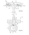
- FIG. 1 of the accompanying drawings is a schematic diagram of a conventional fuel injection system 10 for an internal combustion engine.
- the fuel injection system 10 comprises a plurality of fuel injectors 12. Each injector 12 is arranged to deliver an atomised spray of high-pressure fuel to a respective combustion chamber (not shown) of the engine.
- the injectors 12 receive fuel at high pressure from an accumulator volume or rail 14, by way of high-pressure supply lines 16.
- the rail 14 comprises a reservoir for high-pressure fuel.
- Delivery of fuel from the injectors 12 is controlled by an electronic control unit 18.
- the electronic control unit 18 sends an actuation signal to the injector 12, which causes actuation of a delivery valve (not shown) of the injector 12.
- Fuel is pumped to the rail 14 from a storage tank 20 by a fuel pump assembly 22.
- the fuel pump assembly 22 includes a low-pressure transfer pump 24, which serves to convey fuel from the tank 20 to the pump assembly 22, and a high-pressure pump 26 which elevates the pressure of the fuel to the injection pressure, typically of the order of 2000 bar.
- Fuel is conveyed from the tank 20 to the pump assembly 22 by way of a low-pressure fuel line 28, and from the pump assembly 22 to the rail by way of a high-pressure fuel line 30.
- An inlet metering valve 32 under the control of the engine control unit 18, is provided between the transfer pump 24 and the high-pressure pump 26 of the pump assembly 22.
- the inlet metering valve 32 determines how much fuel reaches the high-pressure pump 26, for subsequent pressurisation and delivery to the rail 14.
- the fuel pressure in the rail 14 is regulated to a target value by the electronic control unit 18.
- a pressure-limiting valve 36 and return line 38 prevent the rail pressure exceeding a pre-determined acceptable level.
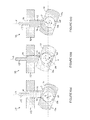
- the high-pressure pump 26 comprises a pumping head 50, shown schematically in Figure 2 , which is arranged to receive a reciprocable pumping plunger or pumping element 52.
- the pump 26 further comprises a drive assembly 54, shown schematically in Figure 3 , for driving reciprocal movement of the pumping element 52. It should be noted that the cross-sectional views of the pumping head 50 and the drive assembly 54 in Figures 2 and 3 respectively are not to scale.
- the pumping head 50 comprises a housing 56 that includes a blind bore 58.
- the pumping element 52 is slidably received within the bore 58.
- a pumping chamber 60 at the blind end of the bore 58 is defined in part by the pumping member 52 and in part by the bore 58.
- the pumping head 50 further comprises a spring-biased inlet valve 62 and a spring-biased outlet valve 64.
- a spring-biased inlet valve 62 When the pumping element 52 moves downwards (referred to as a filling stroke or return stroke of the pumping element 52), the volume of the pumping chamber 60 increases, the outlet valve 64 closes, and the inlet valve 62 opens when the pressure differential across it reaches a first predetermined level. Fuel is then admitted to the pumping chamber 60 from a fuel supply passage 63, through the inlet valve 62. The fuel supply passage 63 is fed with fuel from the inlet metering valve (32 in Figure 1 ).
- the pumping element 52 moves upwards (referred to as a pumping stroke or forward stroke of the pumping element 52), the volume of the pumping chamber 60 decreases.
- the inlet valve closes 62, and the pressure of fuel in the pumping chamber 60 increases.
- the outlet valve 64 is arranged to open when the pressure differential across it reaches a second pre-determined level. Fuel is then delivered through the outlet valve 64 from the pumping chamber 60, for delivery to the fuel rail 14 through an outlet passage 65.
- the second pre-determined differential pressure level at a high level, for example 2000 bar or more, the fuel rail 14 can be pressurised to a suitably high pressure for injection.
- the drive assembly 54 comprises a housing 70, also known as a cam box, which houses a cylindrical cam 72.
- the housing 70 is only partially shown in Figure 3 .
- the cam 72 is driven in eccentric rotational movement by a drive shaft (not shown in Figure 3 ) that extends through the housing 70, so that the cylinder axis C of the cam describes a circular path around the axis A of the drive shaft (which extends normal to the drawing plane in Figure 3 ) as the drive shaft rotates.
- the path described by the edge of the cam 72 as it rotates is indicated by the dashed line P in Figure 3 .
- the drive shaft has a smaller diameter than the cam 72.
- the cam 72 carries a cam ring or rider 74, which includes a central cylindrical aperture 76 for receiving the cam 72.
- the rider 74 includes a flattened surface region or flat 78, which is arranged to cooperate with a cam follower or tappet 80 that acts as a drive member for the pumping element 52.
- the cam 72 is free to rotate in the aperture 76, so that the orientation of the flat 78 of the rider 74 remains horizontal in use.
- the tappet 80 is guided for reciprocal movement through an opening 82 in the housing 70, and is coupled to the pumping element 52 so that movement of the tappet 80 causes movement of the pumping element 52.
- the tappet 80 includes a flat base surface 84 that is held in sliding contact with the flat 78 of the cam rider 74 by a biasing spring 86.
- the housing 70 contains a lubricant (conveniently fuel) that lubricates the sliding interfaces between the tappet 80 and the rider 74 and between the tappet and the wall of the opening 82.
- the flat 78 of the rider 74 slides laterally across the bottom surface 84 of the tappet 80 along a sliding axis (arrow S in Figure 3 ).
- the rider 74 moves from left to right in Figure 3 when the cam 72 moves from 90° before TDC to 90° after TDC, for example as shown in Figures 4(a) and 4(b) , and from right to left when the cam 72 moves from 90° after TDC to 90° before TDC, for example as shown in Figure 4(c) .
- the bottom surface 84 of the tappet 80 keeps the flat 78 of the rider 74 oriented in a plane normal to the pumping axis Q. Further guide means for the rider and/or the tappet 80 may be provided.
- a second pumping head may be mounted diametrically opposite the pumping head 50 shown in Figure 3 .
- a pumping element (not shown) associated with the second pumping head is driven by a tappet (not shown) that cooperates with a second flat 78a provided on the rider 74.
- the second pumping head provides the high-pressure pump 26 with extra pumping capacity, and also helps to balance the moving components of the pump 26.
- the maximum delivery pressure achievable by the high-pressure pump 26 depends, in part, on the stroke length of the pumping element 52.
- the stroke length is the distance travelled by the pumping element 52 between the start and the end of the forward stroke. With a longer stroke length, the volume change of the pumping chamber 60 is greater, and so the fuel in the pumping chamber 60 is elevated to a higher pressure.
- the stroke length is twice the distance between the drive shaft axis A and the cam axis C.
- the stroke length of the pumping element 52 can therefore be increased by increasing the offset distance between the drive shaft axis A and the cam axis C, and therefore the eccentricity of the cam 72 with respect to the drive shaft.
- the maximum offset distance between the drive shaft axis A and the cam axis C is, in practice, equal to the difference between the radius of the cam 72 and the radius of the drive shaft, since otherwise the cam rider 74 would not be able to pass over the drive shaft during manufacture to reach the cam 72. Accordingly, to increase the maximum offset distance between the drive shaft axis A and the cam axis C, a larger-diameter cam 72 must be used.
- the high-pressure pump 26 must be able to deliver a sufficient quantity of fuel to the rail 14 to meet the demand from the fuel injectors 12. At particularly high engine loads, the fuel demand can be considerable.
- One solution to maintaining sufficient fuel output from the high-pressure pump 26 is to increase the drive speed of the drive shaft, to increase the rate of pumping.
- the pumping rate can, however, be limited by the ability of the biasing spring 86 to keep the tappet 80 in contact with the rider 74 on the return stroke of the pumping element 52. Also, as the pumping rate increases, the risk of fatigue damage to the spring 86 increases.
- the present invention resides in a pumping assembly comprising a cam arranged for eccentric rotation about a drive shaft axis, a cam rider mounted on the cam, a cam follower arranged for reciprocal movement in a direction parallel to a cam follower axis, the cam follower being cooperable with the rider by way of a sliding interface to define a sliding axis, and a pumping element associated with the cam follower and arranged to reduce the volume of a pumping chamber during a forward stroke and to increase the volume of the pumping chamber during a reverse stroke.
- the rider is driveable by the cam in a direction having a first component parallel to the cam follower axis and a second component in a direction perpendicular to the cam follower axis.
- the sliding axis is inclined at a non-perpendicular angle to the cam follower axis, such that both the first component and the second component of movement of the rider give rise to movement of the cam follower in the direction parallel to the cam follower axis.
- the stroke length of the pumping element in a pumping assembly according to the first aspect of the invention is greater than the stroke length in a conventional arrangement having a cam with the same diameter and position with respect to the drive shaft axis, in which the sliding axis is perpendicular to the cam follower axis such that only the first component of movement of the rider is converted into reciprocal linear motion of the cam follower.
- the present invention provides a pumping assembly capable of higher pressure and higher volume output than previously-known pumping assemblies in which the sliding axis is perpendicular to the cam follower axis.
- the cam follower axis is perpendicular to the drive shaft axis.
- the second component of movement of the rider may be perpendicular to the drive shaft axis.
- the cam follower may be cooperable with the rider by way of first and second sliding interfaces that are parallel to the sliding axis.
- the cam follower may comprise first and second surfaces that cooperate with the rider at the first and second sliding interfaces, respectively.
- the forward stroke of the pumping element may be driven when the rider thrusts against the first surface during movement of the rider and the return stroke of the pumping element is driven when the rider thrusts against the second surface during movement of the rider. In this way, both the forward stroke and the return stroke of the pumping element are driven by the cam, by way of the rider and the cam follower.
- the present invention also resides, in a second aspect, to a pumping assembly that comprises a cam arranged for eccentric rotation about a drive shaft axis, a cam rider that cooperates with the cam, a cam follower arranged for reciprocal movement in a direction parallel to a cam follower axis that is perpendicular to the drive shaft axis, and a pumping element associated with the cam follower and arranged to reduce the volume of a pumping chamber during a forward stroke and to increase the volume of the pumping chamber during a reverse stroke.
- the cam follower comprises first and second surfaces that cooperate with the rider at first and second sliding interfaces, respectively.
- the forward stroke of the pumping element is driven when the rider thrusts against the first surface during movement of the rider and the return stroke of the pumping element is driven when the rider thrusts against the second surface during movement of the rider.
- the cam rider is mounted on the cam.
- both the forward stroke and the return stroke of the pumping element are driven by the cam, by way of the rider and the cam follower. Accordingly, it is not necessary to provide a biasing spring to keep the cam follower in contact with the rider. Therefore, since the maximum rate of pumping is not limited by the capabilities of a biasing spring, the pumping assembly of the second aspect of the invention can operate at an increased pumping rate. Furthermore, because a force is applied to the cam follower by the cam throughout the whole pumping cycle, smooth and stable reciprocal movement of the cam follower and the pumping element can be achieved.
- the cam follower when the cam follower comprises first and second surfaces that cooperate with the rider at first and second sliding interfaces, respectively, the cam follower may include a first cross member comprising the first surface and a second cross member comprising the second surface.
- the first and second cross members may be disposed on opposite sides of the rider.
- the cam follower may include at least one connecting member that connects the first cross member to the second cross member.
- the cam follower may define, at least in part, a volume for receiving the rider and the cam.
- the volume may receive a lubricating fluid, such a fuel, in use of the pumping assembly.
- the cam follower comprises first and second connecting members that connect respective ends of the first cross member to corresponding ends of the second cross member, such that the first and second cross members and the first and second connecting members define, at least in part, the volume for receiving the rider and the cam.
- the sliding interface may comprise at least one flattened region of the rider for cooperation with a surface of the cam follower.
- the pumping assembly may further comprise a housing that receives the cam, the rider and the cam follower.
- the housing guides the cam follower for reciprocal movement in a direction parallel to the cam follower axis.
- the cam follower may include guide members arranged in sliding contact with a wall of the housing for guiding the reciprocal movement of the cam follower.
- the guide members may comprise the connecting members that connect the respective ends of the first cross member to corresponding ends of the second cross member, when present.
- the cam follower may comprise a first drive member for driving the pumping element, wherein the drive member extends out of the housing.
- the cam follower may further comprise a second drive member for driving a further pumping element, in which case the second drive member may extend out of the housing in an opposite direction to the first drive member.
- the or each drive member may be integral with or connected to the cam follower, and/or integral with or connected to the pumping element.
- the pumping assembly may include fluid flow means for permitting fluid flow through or past the rider and/or the cam follower during movement of the rider and/or the cam follower.
- the fluid flow means may comprise at least one fluid flow passage in the cam follower.
- the invention resides in a high-pressure fuel pump for a fuel injection system, comprising a pumping assembly according to the first or second aspects of the invention, and a pump head that includes the pumping chamber.
- Figure 5 shows a drive assembly 100 for a pumping arrangement, for use as a high-pressure fuel pump in a fuel injection system.
- the drive assembly 100 includes a housing 102, only part of which is shown in Figure 5 , which houses a cylindrical cam 104.
- the cam 104 is mounted eccentrically on a drive shaft (not shown in Figure 5 ), so that the cylinder axis C of the cam 104 is parallel to, but offset from, the axis A of the drive shaft.
- the cam 104 rotates eccentrically so that the outermost edge of the cam 104 describes a path shown by the dashed line P in Figure 5 .
- the cam 104 carries a cam ring or rider 106.
- the cam 104 is received in a cylindrical aperture 108 in the rider 106.
- the rider 106 includes first and second flattened regions or flats 110, 110a, disposed either side of the aperture 108.
- the flats 110, 110a are parallel to one another, and are inclined at an angle with respect to the horizontal in the orientation shown in Figure 5 .
- a tappet or cam follower 112 is slidably received in an aperture 114 in the housing 102.
- the cam follower 112 is guided for linear reciprocal movement by the aperture 114 along a pumping axis Q.
- the cam follower 112 includes a drive member 158 that is coupled to a pumping element (not shown), such as a pumping plunger, that cooperates with a suitable pumping head mounted outside the housing 102.
- a pumping head such as that shown in Figure 2 may be provided.
- the pumping element is driven in reciprocal motion by the cam follower 112 so as to pump fluid to an outlet of the pumping head at high pressure during a forward or pumping stroke, and to draw fluid into the pumping head from an inlet during a return or filling stroke.
- the operation of the pumping head is as described above with reference to Figure 2 .
- the cam follower 112 includes an end surface 116 that is inclined to the horizontal in the orientation shown in Figure 5 .
- the angle of inclination of the flats 110, 110a of the rider 106 matches the angle of inclination of the end surface 116 of the cam follower 112, so the end surface 116 of the cam follower 112 is in sliding contact with the uppermost flat 110 of the rider 106, to define a sliding interface between the rider 106 and the cam follower 112.
- a biasing spring (not shown).
- the sliding interface between the rider 106 and the cam follower 112 lies in a plane having a normal direction that is inclined at an angle to the pumping axis Q. Said another way, the rider 106 and the cam follower 112 slide with respect to one another along a sliding axis (indicated by arrow S) that is inclined at a non-perpendicular angle to the pumping axis.
- the cam 104 is rotatable relative to the rider 106 so that the orientation of the rider 106 remains constant in use.
- Figure 6(a) shows the mechanism when the cam 104 is approximately mid-way between bottom dead centre (BDC) and top dead centre (TDC).
- BDC bottom dead centre
- TDC top dead centre
- the flat 110 of the rider 106 slides along the end surface 116 of the cam follower 112, so that the rider 106 moves to the right in the drawings relative to the cam follower 112.
- both the upward and the horizontal components of movement of the rider 106 result in upward movement of the cam follower 112, and drive the forward stroke of the pumping element.
- Figure 6(b) shows the drive assembly when the cam 104 has reached a position just after TDC.
- the rider 106 is now moving in a direction having a downward component of movement and a horizontal component of movement (to the right in Figure 6(b) ).
- the cam follower 112 would be at a lower position than when the cam 104 is at TDC.
- the cam follower 112 has moved further upwards, because the rider 106 has moved further to the right with respect to the cam follower 112. Therefore the inclination of the flat 110 increases the upward displacement of the cam follower 112, and hence increases the length of the pumping stroke of the pumping element.
- Figure 6(c) shows the drive assembly when the cam 104 has reached a position approximately 45° before BDC.
- the rider 106 is now moving in a direction having a downward component of movement and a horizontal component of movement (towards the left in Figure 6(c) ).
- the rider 106 moves to the left with respect to the cam follower 112, so that both the downward and horizontal components of movement of the rider 106 give rise to downward movement of the cam follower 112, thereby driving the return stroke of the pumping element under the influence of the biasing spring.
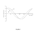
- Figure 7 is a graph showing the relative displacement of the cam follower 112 with respect to cam angle, where a cam angle of 0° or 360° represents TDC and a cam angle of 180° represents BDC.
- the solid line marked "I" in Figure 7 corresponds to a drive mechanism as shown in Figures 5 to 6(c) , in which the sliding axis S is inclined at an angle of 25° to the horizontal (equivalent to an angle of 65° to the pumping axis Q).
- the dashed line marked "H" in Figure 7 corresponds to a drive mechanism such as that shown in Figure 3 , in which the sliding axis is at an angle of 90° to the pumping axis Q (i.e., in Figure 3 , the sliding axis S between the tappet 80 and the rider 74 is perpendicular to the pumping axis Q).
- cam follower 112 Although only one cam follower 112 is shown in Figures 5 to 6(c) , it will be appreciated that a second cam follower with an associated pumping element and pumping head could be provided, to cooperate with the lowermost flat 110a of the rider 106.
- suitable guide means may be provided to guide linear movement of the cam follower 112.
- a linear bearing sleeve can be used to guide movement of the follower 112 in the housing aperture 114.
- the cam follower 112 comprises guide means in the form of guiding members that extend laterally in opposite directions from the follower 112 to engage slidingly with internal walls of the housing 102.
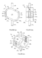
- FIG. 8 Another example of suitable guide means is embodied in a drive assembly 200 according to a second embodiment of the invention, which is shown in cross-section in Figure 8 .
- the drive assembly 200 of Figure 8 includes a housing 202, which houses a cylindrical cam 204.
- the cam 204 is mounted eccentrically on a drive shaft, the position of which is indicated by the dashed line 205 in Figure 8 .
- the cylinder axis C of the cam 204 is parallel to, but offset from, the axis A of the drive shaft.
- the cam 204 rotates eccentrically so that the outermost edge of the cam 204 describes a path shown by the dashed line P in Figure 8 .
- the cam 204 carries a cam ring or rider 206.
- the cam 204 is received in a cylindrical aperture 208 in the rider 206.
- the rider 206 includes parallel first and second flattened regions or flats 210, 21 0a, disposed either side of the aperture 208.
- a cam follower 212 cooperates with the rider 206, and is guided for linear reciprocal movement along a pumping axis Q, as will be described in more detail below.
- the cam follower 212 defines an internal volume 250, in which the rider 206 is slidably received.
- the cam follower 212 includes a first or upper inclined member 252 and a parallel second or lower inclined member 252a, each of which extends at a non-perpendicular angle to the pumping axis Q.
- the cam follower further includes a first vertical member 254 that extends downwardly from the right-hand end of the first inclined member 252, and a second vertical member 254a that extends upwardly from the left-hand end of the second inclined member 252a.
- a first curved link member 256 joins the left-hand end of the first inclined member 252 to the top end of the second vertical member 254a, and a second curved link member 256a joins the right-hand end of the second inclined member 252a to the bottom end of the first vertical member 254.
- the inclined members 252, 252a, the vertical members 254, 254a and the link members 256, 256a define a cage-like structure that encloses the volume 250, and the rider 206, therewithin.
- the volume 250 is open to the front and rear faces of the cam follower 212.
- the angle of inclination of the flats 210, 210a of the rider 206 matches the angle of inclination of the inclined members 252, 252a of the cam follower 212, so a lower surface 216 of the first inclined member 252 of the cam follower 212 is in sliding contact with the uppermost flat 210 of the rider 206, and so an upper surface 216a of the second inclined member 252a is in sliding contact with the lowermost flat 210a. Therefore two sliding interfaces are defined between the rider 206 and the cam follower 212, each lying in a plane having a normal direction that is inclined at an angle to the pumping axis Q.
- the rider 206 and the cam follower 212 slide with respect to one another along a sliding axis S that is inclined at a non-perpendicular angle to the pumping axis Q.
- the cam 204 is rotatable relative to the rider 206.
- First and second drive members 258, 258a project upwardly and downwardly from the first and second inclined members 252, 252a, respectively. Each drive member 258, 258a cooperates with an associated pumping element (not shown).
- the drive assembly 200 is provided with an upper and a lower pumping head, disposed opposite one another across the drive shaft axis A, and each pumping head receives a respective upper and lower one of the pumping elements.
- the pumping heads may be of a known type, such as that described above with reference to Figure 2 .
- the housing 202 comprises a wall part 260, which is visible in cross-section in Figure 8 , and front and rear face plates (not shown) that are attachable to the front and rear sides of the wall part 260.
- the face plates include apertures that allow the drive shaft to pass through the housing 202.
- the wall part 260 of the housing 202 has an irregular generally hexagonal cross-section, and an inner wall 262 of the wall part 260 defines a housing volume 263 in which the cage-like structure of the cam follower 212 is received.
- the inner wall 262 includes first and second vertical guide surfaces 264, 264a, and the first and second vertical members 254, 254a respectively of the cam follower 212 are in sliding contact with the vertical guide surfaces 264, 264a.
- the inclined members 252, 252a and the link members 256, 256a of the cam follower 212 are spaced from the inner wall 262 of the housing wall part 260, so that the cam follower 212 can move up and down within the housing volume 263.
- the housing wall part 260 includes first and second apertures 266, 266a, through which the drive members 258, 258a extend.
- the drive members 258, 258a are a clearance fit in the apertures 266, 266a, and so in this embodiment the cam follower 212 is not guided by cooperation with the housing 202 at the apertures 266, 266a, but instead by cooperation between the vertical members 254, 254a of the cam follower 212 and the internal vertical guide surfaces 262, 262a of the housing 202.
- the front face 269 of the cam follower 212 and the rear face 269a of the cam follower 212 are in sliding engagement with the internal surfaces of the front and rear face plates (not shown) of the housing 202 in use. Accordingly, cooperation between the front and rear faces 269, 269a of the cam follower 212 and the face plates of the housing 202 also acts to guide the movement of the cam follower 212.
- the housing volume 263 and the volume 250 defined by the cam follower 212 contain lubricating fluid, such as fuel, which lubricates the sliding interfaces between the vertical members 254, 254a of the cam follower 212 and the guide walls 262, 262a of the housing 202, the sliding interfaces between the inclined members 252, 252a of the housing cam follower 212 and the flats 210, 210a of the rider 206, and also the sliding interfaces between the front and rear faces 269, 269a of the cam follower 212 and the front and rear face plates of the housing 202.
- the sizes of the housing volume 263 and the cam follower volume 250 change cyclically as the cam follower 212 moves with respect to the housing 202, and as the rider 206 moves with respect to the cam follower 212.
- the cam follower 212 is provided with fluid flow means.
- the fluid flow means include vertically-extending recesses or channels 268, 268a in the outer surfaces of the first and second vertical members 254, 254a of the cam follower 212.
- One channel 268 extends from the first inclined member 252 to the second link member 256a, and the other channel 268a extends from the second inclined member 252a to the first link member 256.
- the channels 268, 268a allow fluid to flow past the cam follower 212 as it moves up and down within the housing volume 263.
- the fluid flow means further includes first and second slots 270, 270a that extend through the first and second vertical members 254, 254a, respectively, of the cam follower 212, to communicate with the respective channel 268, 268a.
- the fluid flow means includes first and second drillings 272, 272a, that extend through the first and second link members 256, 256a of the cam follower 212, respectively.
- the slots 270, 270a and drillings 272, 272a allow fluid transfer between the volume 250 defined by the cam follower 212 and the housing volume 263.
- this second embodiment has the advantage that the displacement of the cam follower 212, and hence the length of the pumping stroke, is larger than would be achieved using a conventional rider with a horizontal sliding interface between the rider and the cam follower.
- a further advantage of the second embodiment of the invention arises because the rider 206 is embraced between the inner faces of the first and second inclined members 252, 252a of the cam follower 212.
- the first drive member 258 moves upwards, driving the forward stroke of the upper pumping element.
- the second drive member 258a also moves upwards, driving the return stroke of the lower pumping element.
- the first and second drive members 258, 258a both move downwards, driving the return stroke of the upper pumping element and the pumping stroke of the lower pumping element, respectively.
- both the forward and return strokes of both pumping elements are driven by the cooperative movement of the rider 206 against the cam follower 212.
- the drive assembly 200 of the second embodiment of the invention does not therefore require biasing springs or other biasing means for driving the return strokes of the pumping elements.
- the cam follower 212 remains engaged with the rider 206 by virtue of the cage-like arrangement of the cam follower 212, and equal force is applied to the drive members 258, 258a in both the forward and return strokes.
- the drive assembly 200 of the second embodiment of the invention can be operated at higher speeds and has a higher resistance to fatigue damage than conventional drive assemblies.
- FIG. 10 is a schematic cross-sectional view of a drive assembly 300 according to a third embodiment of the present invention.
- the drive assembly 300 of Figure 10 includes a housing 302, which houses a cylindrical cam 304.
- the cam 304 is mounted eccentrically on a drive shaft, the position of which is indicated by the dashed line 305 in Figure 10 .
- the cylinder axis C of the cam 304 is parallel to, but offset from, the axis A of the drive shaft.
- the cam 304 carries a cam ring or rider 306 that includes parallel first and second flattened regions or flats 310, 310a, disposed either side of a cam-receiving aperture 308.
- the cam 304 is rotatable relative to the rider 306.
- a cam follower 312 cooperates with the rider 306, and is guided for linear reciprocal movement along a pumping axis Q.
- the cam follower 312 defines an internal volume 350, in which the rider 306 is slidably received.
- the cam follower 312 includes a first or upper horizontal member 352 and a parallel second or lower horizontal member 352a, each of which extend in a plane that lies normal to the pumping axis Q.
- the cam follower further includes a first vertical member 354 that connects the right-hand ends of the horizontal members 352, 352a, and a second vertical member 354a that connects the left-hand ends of the horizontal members 352, 352a.
- the vertical and horizontal members 352, 352a; 354, 354a define a cage-like structure that encloses the volume 350, and the rider 306, therewithin.
- the volume 350 is open to the front and rear faces of the cam follower 312, but is closed by front and rear face plates (not shown) of the housing 302.
- a lower surface 316 of the first horizontal member 352 of the cam follower 312 is in sliding contact with the uppermost flat 310 of the rider 306, and an upper surface 316a of the second horizontal member 352a is in sliding contact with the lowermost flat 310a. Therefore two sliding interfaces are defined between the rider 306 and the cam follower 312, each lying in a plane having a normal direction that is parallel to the pumping axis Q.
- First and second drive members 358, 358a project upwardly and downwardly from the first and second horizontal members 352, 352a, respectively, through apertures 366, 366a in the housing 302. As in the second embodiment of the invention, in this third embodiment each drive member 358, 358a cooperates with an associated pumping element (not shown).
- the drive assembly 300 is provided with an upper and a lower pumping head, disposed opposite one another across the drive shaft axis A, and each pumping head receives a respective upper and lower one of the pumping elements.
- the pumping heads may be of a known type, such as that described above with reference to Figure 2 .
- the housing 302 comprises a wall part 360, which is visible in cross-section in Figure 10 , and front and rear face plates (not shown) that are attachable to the front and rear sides of the wall part 360.
- the face plates include apertures that allow the drive shaft to pass through the housing 302.
- the wall part 360 of the housing 302 has a generally square cross-section, and an inner wall 362 of the wall part 360 defines a generally cuboidal housing volume 363 in which the cage-like structure of the rider 312 is received.
- the inner wall 362 includes first and second vertical guide surfaces 364, 364a, and the first and second vertical members 354, 354a respectively of the cam follower 312 are in sliding contact with the vertical guide surfaces 364, 364a.
- the cam follower 312 can therefore move up and down in guided movement within the housing volume 363.
- the front and rear faces (not shown) of the cam follower 312 are in sliding contact with the internal surfaces of the front and rear face plates (not shown) of the housing 302 in use. Accordingly, cooperation between the front and rear faces of the cam follower 312 and the face plates of the housing 302 also acts to guide the movement of the cam follower 312.
- the cam follower 312 is provided with fluid flow means in the form of vertically-extending channels 368, 368a in the outer surfaces of the first and second vertical members 354, 354a of the cam follower 312, first and second slots 370, 370a that extend through the first and second vertical members 354, 354a, respectively, and first and second drillings 372, 372a, that extend through the first and second horizontal members 354, 354a of the cam follower 312, respectively.
- Operation of the drive assembly 300 of the third embodiment of the invention is similar to the operation of the drive assembly 200 of the second embodiment of the invention, as described above.
- this third embodiment because the flats 310, 310a of the rider 306 and the horizontal members 352, 352a of the cam follower 312 slide along sliding axes (S) that are perpendicular to the pumping direction Q, only the vertical component of movement of the rider 306 is converted to movement of the cam follower 312 in a direction parallel to the pumping axis Q.
- the length of the pumping stroke is therefore equal to twice the offset between the drive shaft axis A and the cam axis C.
- both the forward and return strokes of both pumping elements are driven by the cooperative movement of the rider 306 against the cam follower 312.
- the drive assembly 300 of the third embodiment of the invention advantageously does not therefore require biasing springs or other biasing means for driving the return strokes of the pumping elements.
- a drive member of the cam follower cooperates with a pumping element.
- the drive member and pumping element may be integrally formed, for example so that a distal end of the drive member forms the pumping element.
- the pumping element may instead be a separate component that is attached to or otherwise connected to the drive member.
- the drive member may be a separate component that is attached to the cam follower.
- the pumping element, the drive member and the cam follower may be integrally formed as one component.
- the members that make up the cage-like cam follower in the second and third embodiments of the invention may be parts of a single, integrally formed component, or may be separate or combined components that are assembled to form the cam follower.
- the fluid flow means that allow fluid flow past the cam follower as it reciprocates within the housing volume may be embodied in a different form to the channels described above.
- channels or flow passages could be provided in the housing wall, in addition to or instead of the channels in the cam follower faces.
- Further channels, drillings and other flow passages could be provided in the cam follower, and flow means could also be provided in the rider or in the faces of the cam follower that cooperate with the rider to allow flow past the rider as it reciprocates.
- the cam follower may take any suitable form.
- the cam follower may be of any suitable design that provides two parallel faces for sliding engagement with the flats of the rider, and means for guiding the cam follower in linear reciprocal movement.
- the pumping assembly of the present invention is particularly suitable for use as a high-pressure fuel pump of a fuel injection system, it will be appreciated that the pumping assembly could also be used for any other pumping application with similar requirements.
Landscapes
- Engineering & Computer Science (AREA)
- Mechanical Engineering (AREA)
- General Engineering & Computer Science (AREA)
- Chemical & Material Sciences (AREA)
- Combustion & Propulsion (AREA)
- Reciprocating Pumps (AREA)
Abstract
A pumping assembly (100; 200) suitable for use as a high-pressure fuel pump of a fuel injection system is disclosed. The pumping assembly comprises a cam (104; 204) arranged for eccentric rotation about a drive shaft axis (A), a cam rider (106; 206) mounted on the cam (104; 204), a cam follower (112; 212) arranged for reciprocal movement in a direction parallel to a cam follower axis (Q), the cam follower (112; 212) being cooperable with the rider (106; 206) by way of a sliding interface (110, 116; 210, 216) to define a sliding axis (S), and a pumping element associated with the cam follower (112; 212) and arranged to reduce the volume of a pumping chamber during a forward stroke and to increase the volume of the pumping chamber during a reverse stroke. The rider (106; 206) is driveable by the cam (104; 204) in a direction having a first component parallel to the cam follower axis (Q) and a second component in a direction perpendicular to the cam follower axis (Q). In one embodiment, the sliding axis (S) is inclined at a non-perpendicular angle to the cam follower axis (Q), such that both the first component and the second component of movement of the rider (106; 206) give rise to movement of the cam follower (112; 212) in the direction parallel to the cam follower axis (Q). In another embodiment, the cam follower (212) comprises first and second surfaces (216, 216a) that cooperate with the rider (206) at the first and second sliding interfaces (210, 216; 210a, 216a), respectively, and the forward stroke of the pumping element is driven when the rider (206) thrusts against the first surface (216) during movement of the rider (206) and the return stroke of the pumping element is driven when the rider (206) thrusts against the second surface (216a) during movement of the rider (206).
Description
- This invention relates to a pumping assembly for pumping a fluid. In particular, but not exclusively, the invention relates to a pumping assembly suitable for use in a high-pressure fuel pump of a fuel injection system for an internal combustion engine.
-
Figure 1 of the accompanying drawings is a schematic diagram of a conventional fuel injection system 10 for an internal combustion engine. - The fuel injection system 10 comprises a plurality of
fuel injectors 12. Eachinjector 12 is arranged to deliver an atomised spray of high-pressure fuel to a respective combustion chamber (not shown) of the engine. Theinjectors 12 receive fuel at high pressure from an accumulator volume or rail 14, by way of high-pressure supply lines 16. The rail 14 comprises a reservoir for high-pressure fuel. - Delivery of fuel from the
injectors 12 is controlled by anelectronic control unit 18. When a fuel injection from one of theinjectors 12 is required, theelectronic control unit 18 sends an actuation signal to theinjector 12, which causes actuation of a delivery valve (not shown) of theinjector 12. - Fuel is pumped to the rail 14 from a storage tank 20 by a
fuel pump assembly 22. Thefuel pump assembly 22 includes a low-pressure transfer pump 24, which serves to convey fuel from the tank 20 to thepump assembly 22, and a high-pressure pump 26 which elevates the pressure of the fuel to the injection pressure, typically of the order of 2000 bar. Fuel is conveyed from the tank 20 to thepump assembly 22 by way of a low-pressure fuel line 28, and from thepump assembly 22 to the rail by way of a high-pressure fuel line 30. - An
inlet metering valve 32, under the control of theengine control unit 18, is provided between thetransfer pump 24 and the high-pressure pump 26 of thepump assembly 22. Theinlet metering valve 32 determines how much fuel reaches the high-pressure pump 26, for subsequent pressurisation and delivery to the rail 14. The fuel pressure in the rail 14 is regulated to a target value by theelectronic control unit 18. A pressure-limitingvalve 36 and return line 38 prevent the rail pressure exceeding a pre-determined acceptable level. - The high-
pressure pump 26 comprises apumping head 50, shown schematically inFigure 2 , which is arranged to receive a reciprocable pumping plunger or pumping element 52. Thepump 26 further comprises adrive assembly 54, shown schematically inFigure 3 , for driving reciprocal movement of the pumping element 52. It should be noted that the cross-sectional views of thepumping head 50 and thedrive assembly 54 inFigures 2 and 3 respectively are not to scale. - The pumping
head 50 comprises ahousing 56 that includes ablind bore 58. The pumping element 52 is slidably received within thebore 58. Apumping chamber 60 at the blind end of thebore 58 is defined in part by the pumping member 52 and in part by thebore 58. As the pumping element 52 is driven in reciprocal motion along a pumping axis Q by thedrive assembly 54, the volume of thepumping chamber 60, and hence the pressure in thepumping chamber 60, increases and decreases accordingly. - The pumping
head 50 further comprises a spring-biased inlet valve 62 and a spring-biased outlet valve 64. When the pumping element 52 moves downwards (referred to as a filling stroke or return stroke of the pumping element 52), the volume of thepumping chamber 60 increases, theoutlet valve 64 closes, and theinlet valve 62 opens when the pressure differential across it reaches a first predetermined level. Fuel is then admitted to thepumping chamber 60 from afuel supply passage 63, through theinlet valve 62. Thefuel supply passage 63 is fed with fuel from the inlet metering valve (32 inFigure 1 ). - When the pumping element 52 moves upwards (referred to as a pumping stroke or forward stroke of the pumping element 52), the volume of the
pumping chamber 60 decreases. The inlet valve closes 62, and the pressure of fuel in thepumping chamber 60 increases. Theoutlet valve 64 is arranged to open when the pressure differential across it reaches a second pre-determined level. Fuel is then delivered through theoutlet valve 64 from thepumping chamber 60, for delivery to the fuel rail 14 through anoutlet passage 65. By setting the second pre-determined differential pressure level at a high level, for example 2000 bar or more, the fuel rail 14 can be pressurised to a suitably high pressure for injection. - Referring to
Figure 3 , thedrive assembly 54 comprises ahousing 70, also known as a cam box, which houses acylindrical cam 72. Thehousing 70 is only partially shown inFigure 3 . Thecam 72 is driven in eccentric rotational movement by a drive shaft (not shown inFigure 3 ) that extends through thehousing 70, so that the cylinder axis C of the cam describes a circular path around the axis A of the drive shaft (which extends normal to the drawing plane inFigure 3 ) as the drive shaft rotates. The path described by the edge of thecam 72 as it rotates is indicated by the dashed line P inFigure 3 . The drive shaft has a smaller diameter than thecam 72. - The
cam 72 carries a cam ring orrider 74, which includes a centralcylindrical aperture 76 for receiving thecam 72. Therider 74 includes a flattened surface region or flat 78, which is arranged to cooperate with a cam follower or tappet 80 that acts as a drive member for the pumping element 52. Thecam 72 is free to rotate in theaperture 76, so that the orientation of theflat 78 of therider 74 remains horizontal in use. - The
tappet 80 is guided for reciprocal movement through anopening 82 in thehousing 70, and is coupled to the pumping element 52 so that movement of thetappet 80 causes movement of the pumping element 52. - The
tappet 80 includes aflat base surface 84 that is held in sliding contact with the flat 78 of thecam rider 74 by a biasingspring 86. Thehousing 70 contains a lubricant (conveniently fuel) that lubricates the sliding interfaces between thetappet 80 and therider 74 and between the tappet and the wall of theopening 82. - Operation of the
drive assembly 54 will now be described with reference toFigures 4(a) to 4(c) . In use, the drive shaft rotates about its axis A, in a clockwise direction in the figures, causing eccentric clockwise movement of thecam 72. - Two stages in the movement of the
cam 72 from its lowermost position (bottom dead centre or BDC) to its uppermost position (top dead centre or TDC) are shown inFigures 4(a) and 4(b) . As the drive shaft rotates, thecam 72 carries therider 74 in a path having an upward component, towards the opening 82 in thehousing 70. By virtue of the upward component of movement of therider 74, thetappet 80, is driven upwards by therider 74, so as to drive the forward stroke of the pumping element (52 inFigure 2 ). - Once the
cam 72 reaches TDC, continued rotation of the drive shaft results in thecam 72 carrying therider 74 in a path having a downward component, away from the opening 82 in thehousing 70. The biasingspring 86 keeps thetappet 80 in engagement with the flat 78 of therider 74, so that thetappet 80 moves downwards and the pumping element (52 inFigure 2 ) is therefore driven by thebiasing spring 86 in its return stroke. - When the
cam 72 reaches BDC, as shown inFigure 4(c) , the pumping cycle repeats as the drive shaft continues to rotate. - During the pumping cycle, the flat 78 of the
rider 74 slides laterally across thebottom surface 84 of thetappet 80 along a sliding axis (arrow S inFigure 3 ). Therider 74 moves from left to right inFigure 3 when thecam 72 moves from 90° before TDC to 90° after TDC, for example as shown inFigures 4(a) and 4(b) , and from right to left when thecam 72 moves from 90° after TDC to 90° before TDC, for example as shown inFigure 4(c) . Since lateral movement of thetappet 80 is constrained, thebottom surface 84 of thetappet 80 keeps the flat 78 of therider 74 oriented in a plane normal to the pumping axis Q. Further guide means for the rider and/or thetappet 80 may be provided. - A second pumping head (not shown) may be mounted diametrically opposite the
pumping head 50 shown inFigure 3 . In this case, a pumping element (not shown) associated with the second pumping head is driven by a tappet (not shown) that cooperates with a second flat 78a provided on therider 74. The second pumping head provides the high-pressure pump 26 with extra pumping capacity, and also helps to balance the moving components of thepump 26. - The maximum delivery pressure achievable by the high-
pressure pump 26 depends, in part, on the stroke length of the pumping element 52. The stroke length is the distance travelled by the pumping element 52 between the start and the end of the forward stroke. With a longer stroke length, the volume change of thepumping chamber 60 is greater, and so the fuel in thepumping chamber 60 is elevated to a higher pressure. - In general terms, there is a desire to be able to provide fuel to the injectors at increasing pressures, since increased injection pressure can help to improve injection control, emissions and fuel efficiency. Accordingly, it is desirable to maximise the stroke length of the pumping element 52 of a high-
pressure pump 26. - In the configuration shown in
Figure 3 , in which the pumping axis Q intersects the drive shaft axis A, the stroke length is twice the distance between the drive shaft axis A and the cam axis C. The stroke length of the pumping element 52 can therefore be increased by increasing the offset distance between the drive shaft axis A and the cam axis C, and therefore the eccentricity of thecam 72 with respect to the drive shaft. - The maximum offset distance between the drive shaft axis A and the cam axis C is, in practice, equal to the difference between the radius of the
cam 72 and the radius of the drive shaft, since otherwise thecam rider 74 would not be able to pass over the drive shaft during manufacture to reach thecam 72. Accordingly, to increase the maximum offset distance between the drive shaft axis A and the cam axis C, a larger-diameter cam 72 must be used. - This approach has disadvantages. Increasing the diameter of the
cam 72 increases the inertia of the rotating components, and therefore decreases the efficiency of thepump 26 and potentially increases wear rates on the drive shaft bearings. Also, during assembly, the drive shaft andcam 72 must pass through an aperture in at least one wall of thehousing 70. The drive shaft is held in a bearing in the aperture. The larger thecam 72, the larger the diameter of the bearing required, which increases the cost and complexity of thepump 26. - Another consideration in high-pressure fuel injection is that the high-
pressure pump 26 must be able to deliver a sufficient quantity of fuel to the rail 14 to meet the demand from thefuel injectors 12. At particularly high engine loads, the fuel demand can be considerable. One solution to maintaining sufficient fuel output from the high-pressure pump 26 is to increase the drive speed of the drive shaft, to increase the rate of pumping. - The pumping rate can, however, be limited by the ability of the biasing
spring 86 to keep thetappet 80 in contact with therider 74 on the return stroke of the pumping element 52. Also, as the pumping rate increases, the risk of fatigue damage to thespring 86 increases. - Against this background, it would be desirable to provide pumping arrangements that offer an increase in output pressure and volume that overcome or reduce the problems described above.
- From a first aspect, the present invention resides in a pumping assembly comprising a cam arranged for eccentric rotation about a drive shaft axis, a cam rider mounted on the cam, a cam follower arranged for reciprocal movement in a direction parallel to a cam follower axis, the cam follower being cooperable with the rider by way of a sliding interface to define a sliding axis, and a pumping element associated with the cam follower and arranged to reduce the volume of a pumping chamber during a forward stroke and to increase the volume of the pumping chamber during a reverse stroke.
- The rider is driveable by the cam in a direction having a first component parallel to the cam follower axis and a second component in a direction perpendicular to the cam follower axis. The sliding axis is inclined at a non-perpendicular angle to the cam follower axis, such that both the first component and the second component of movement of the rider give rise to movement of the cam follower in the direction parallel to the cam follower axis.
- Because both the first and second components of movement of the rider are converted into reciprocal linear motion of the cam follower, the distance moved by the cam follower in the direction parallel to the cam follower axis, and hence the stroke length of the pumping element during its forward and return strokes, is increased. In particular, the stroke length of the pumping element in a pumping assembly according to the first aspect of the invention is greater than the stroke length in a conventional arrangement having a cam with the same diameter and position with respect to the drive shaft axis, in which the sliding axis is perpendicular to the cam follower axis such that only the first component of movement of the rider is converted into reciprocal linear motion of the cam follower.
- Accordingly, the present invention provides a pumping assembly capable of higher pressure and higher volume output than previously-known pumping assemblies in which the sliding axis is perpendicular to the cam follower axis.
- In one embodiment, the cam follower axis is perpendicular to the drive shaft axis. The second component of movement of the rider may be perpendicular to the drive shaft axis.
- The cam follower may be cooperable with the rider by way of first and second sliding interfaces that are parallel to the sliding axis. For example, the cam follower may comprise first and second surfaces that cooperate with the rider at the first and second sliding interfaces, respectively. Advantageously, the forward stroke of the pumping element may be driven when the rider thrusts against the first surface during movement of the rider and the return stroke of the pumping element is driven when the rider thrusts against the second surface during movement of the rider. In this way, both the forward stroke and the return stroke of the pumping element are driven by the cam, by way of the rider and the cam follower. Advantageously, therefore, it is not necessary to provide a biasing spring to keep the cam follower in contact with the rider.
- The present invention also resides, in a second aspect, to a pumping assembly that comprises a cam arranged for eccentric rotation about a drive shaft axis, a cam rider that cooperates with the cam, a cam follower arranged for reciprocal movement in a direction parallel to a cam follower axis that is perpendicular to the drive shaft axis, and a pumping element associated with the cam follower and arranged to reduce the volume of a pumping chamber during a forward stroke and to increase the volume of the pumping chamber during a reverse stroke.
- The cam follower comprises first and second surfaces that cooperate with the rider at first and second sliding interfaces, respectively. The forward stroke of the pumping element is driven when the rider thrusts against the first surface during movement of the rider and the return stroke of the pumping element is driven when the rider thrusts against the second surface during movement of the rider. Preferably, the cam rider is mounted on the cam.
- In this second aspect of the invention, both the forward stroke and the return stroke of the pumping element are driven by the cam, by way of the rider and the cam follower. Accordingly, it is not necessary to provide a biasing spring to keep the cam follower in contact with the rider. Therefore, since the maximum rate of pumping is not limited by the capabilities of a biasing spring, the pumping assembly of the second aspect of the invention can operate at an increased pumping rate. Furthermore, because a force is applied to the cam follower by the cam throughout the whole pumping cycle, smooth and stable reciprocal movement of the cam follower and the pumping element can be achieved.
- In either aspect of the invention, when the cam follower comprises first and second surfaces that cooperate with the rider at first and second sliding interfaces, respectively, the cam follower may include a first cross member comprising the first surface and a second cross member comprising the second surface. The first and second cross members may be disposed on opposite sides of the rider.
- The cam follower may include at least one connecting member that connects the first cross member to the second cross member. The cam follower may define, at least in part, a volume for receiving the rider and the cam. The volume may receive a lubricating fluid, such a fuel, in use of the pumping assembly.
- In one embodiment, the cam follower comprises first and second connecting members that connect respective ends of the first cross member to corresponding ends of the second cross member, such that the first and second cross members and the first and second connecting members define, at least in part, the volume for receiving the rider and the cam.
- The sliding interface may comprise at least one flattened region of the rider for cooperation with a surface of the cam follower.
- The pumping assembly may further comprise a housing that receives the cam, the rider and the cam follower. Conveniently, the housing guides the cam follower for reciprocal movement in a direction parallel to the cam follower axis. For example, the cam follower may include guide members arranged in sliding contact with a wall of the housing for guiding the reciprocal movement of the cam follower. The guide members may comprise the connecting members that connect the respective ends of the first cross member to corresponding ends of the second cross member, when present.
- The cam follower may comprise a first drive member for driving the pumping element, wherein the drive member extends out of the housing. The cam follower may further comprise a second drive member for driving a further pumping element, in which case the second drive member may extend out of the housing in an opposite direction to the first drive member. The or each drive member may be integral with or connected to the cam follower, and/or integral with or connected to the pumping element.
- The pumping assembly may include fluid flow means for permitting fluid flow through or past the rider and/or the cam follower during movement of the rider and/or the cam follower. For example, the fluid flow means may comprise at least one fluid flow passage in the cam follower.
- In another aspect, the invention resides in a high-pressure fuel pump for a fuel injection system, comprising a pumping assembly according to the first or second aspects of the invention, and a pump head that includes the pumping chamber.
- Preferred and/or optional features of each aspect of the invention may be used alone or in appropriate combination in the other aspects of the invention also.
-
-
Figure 1 of the accompanying drawings, which has been referred to above, is a schematic diagram of a conventional fuel injection system of an internal combustion engine having a conventional high-pressure fuel pump. -
Figures 2 and 3 , which have also been referred to above, are schematic cross-sectional views of a pumping head and a drive assembly, respectively, of a conventional high-pressure fuel pump for use in the fuel injection system ofFigure 1 . -
Figures 4(a) to 4(c) are schematic cross-sectional views that illustrate the operation of the conventional drive assembly ofFigure 3 . - Embodiments of the present invention will now be described, by way of example only, with reference to the remaining accompanying drawings, in which like reference numerals are used for like features, and in which:
-
Figure 5 is a schematic cross-sectional view of a pumping arrangement according to a first embodiment of the present invention; -
Figures 6(a) to 6(c) are schematic cross-sectional views illustrating the operation of the pumping arrangement ofFigure 5 ; -
Figure 7 is a schematic graph illustrating the relationship between displacement and cam rotation angle for a pumping arrangement such as that shown inFigure 5 , compared to a conventional pumping arrangement; -
Figure 8 is a schematic cross-sectional view of a pumping arrangement according to a second embodiment of the present invention; -
Figures 9(a), 9(b) and 9(c) are front, side and perspective views of a cam follower of the pumping arrangement ofFigure 8 ; and -
Figure 10 is a schematic cross-sectional view of a pumping arrangement according to a third embodiment of the present invention. - Throughout this description, terms such as 'upper', 'lower', 'left', 'right', 'horizontal', 'vertical' and so on relate to the orientation of the components as shown in the accompanying drawings and are used for ease or reference only. It should be understood that the invention could be used in any suitable orientation.
-
Figure 5 shows adrive assembly 100 for a pumping arrangement, for use as a high-pressure fuel pump in a fuel injection system. - The
drive assembly 100 includes ahousing 102, only part of which is shown inFigure 5 , which houses acylindrical cam 104. Thecam 104 is mounted eccentrically on a drive shaft (not shown inFigure 5 ), so that the cylinder axis C of thecam 104 is parallel to, but offset from, the axis A of the drive shaft. In use, when the drive shaft rotates, thecam 104 rotates eccentrically so that the outermost edge of thecam 104 describes a path shown by the dashed line P inFigure 5 . - The
cam 104 carries a cam ring orrider 106. Thecam 104 is received in acylindrical aperture 108 in therider 106. Therider 106 includes first and second flattened regions orflats aperture 108. Theflats Figure 5 . - A tappet or
cam follower 112 is slidably received in anaperture 114 in thehousing 102. Thecam follower 112 is guided for linear reciprocal movement by theaperture 114 along a pumping axis Q. Thecam follower 112 includes adrive member 158 that is coupled to a pumping element (not shown), such as a pumping plunger, that cooperates with a suitable pumping head mounted outside thehousing 102. For example, a known pumping head such as that shown inFigure 2 may be provided. - The pumping element is driven in reciprocal motion by the
cam follower 112 so as to pump fluid to an outlet of the pumping head at high pressure during a forward or pumping stroke, and to draw fluid into the pumping head from an inlet during a return or filling stroke. The operation of the pumping head is as described above with reference toFigure 2 . - Returning to
Figure 5 , thecam follower 112 includes anend surface 116 that is inclined to the horizontal in the orientation shown inFigure 5 . The angle of inclination of theflats rider 106 matches the angle of inclination of theend surface 116 of thecam follower 112, so theend surface 116 of thecam follower 112 is in sliding contact with the uppermost flat 110 of therider 106, to define a sliding interface between therider 106 and thecam follower 112. Contact between theend surface 116 of thecam follower 112 and the flat 110 is maintained by a biasing spring (not shown). - By virtue of the inclination of the cam
follower end surface 116 and the flat 110, the sliding interface between therider 106 and thecam follower 112 lies in a plane having a normal direction that is inclined at an angle to the pumping axis Q. Said another way, therider 106 and thecam follower 112 slide with respect to one another along a sliding axis (indicated by arrow S) that is inclined at a non-perpendicular angle to the pumping axis. Thecam 104 is rotatable relative to therider 106 so that the orientation of therider 106 remains constant in use. - Operation of the pumping mechanism of
Figure 5 will now be described with reference toFigures 6(a) to 6(c) , which show successive stages in operation as the drive shaft rotates in a clockwise direction. -
Figure 6(a) shows the mechanism when thecam 104 is approximately mid-way between bottom dead centre (BDC) and top dead centre (TDC). As thecam 104 rotates in a clockwise direction, towards TDC, the rider moves in a direction having an upward component of movement and a horizontal component of movement (to the right inFigure 6(a) ). The flat 110 of therider 106 slides along theend surface 116 of thecam follower 112, so that therider 106 moves to the right in the drawings relative to thecam follower 112. - By virtue of the angled orientation of the flat 110, both the upward and the horizontal components of movement of the
rider 106 result in upward movement of thecam follower 112, and drive the forward stroke of the pumping element. -
Figure 6(b) shows the drive assembly when thecam 104 has reached a position just after TDC. Therider 106 is now moving in a direction having a downward component of movement and a horizontal component of movement (to the right inFigure 6(b) ). If the flat 110 were horizontal, in this position thecam follower 112 would be at a lower position than when thecam 104 is at TDC. However, because of the angled orientation of the flat 110, in the position shown inFigure 6(b) thecam follower 112 has moved further upwards, because therider 106 has moved further to the right with respect to thecam follower 112. Therefore the inclination of the flat 110 increases the upward displacement of thecam follower 112, and hence increases the length of the pumping stroke of the pumping element. -
Figure 6(c) shows the drive assembly when thecam 104 has reached a position approximately 45° before BDC. Therider 106 is now moving in a direction having a downward component of movement and a horizontal component of movement (towards the left inFigure 6(c) ). Therider 106 moves to the left with respect to thecam follower 112, so that both the downward and horizontal components of movement of therider 106 give rise to downward movement of thecam follower 112, thereby driving the return stroke of the pumping element under the influence of the biasing spring. - As the
cam 104 passes BDC, thecam rider 106 is still moving towards the left, so that thecam follower 112 continues to move downwards. Thus the inclination of the flat 110 also increases the downward displacement of thecam follower 112, and hence increases the length of the return stroke of the pumping element. -
Figure 7 is a graph showing the relative displacement of thecam follower 112 with respect to cam angle, where a cam angle of 0° or 360° represents TDC and a cam angle of 180° represents BDC. The solid line marked "I" inFigure 7 corresponds to a drive mechanism as shown inFigures 5 to 6(c) , in which the sliding axis S is inclined at an angle of 25° to the horizontal (equivalent to an angle of 65° to the pumping axis Q). For comparison, the dashed line marked "H" inFigure 7 corresponds to a drive mechanism such as that shown inFigure 3 , in which the sliding axis is at an angle of 90° to the pumping axis Q (i.e., inFigure 3 , the sliding axis S between thetappet 80 and therider 74 is perpendicular to the pumping axis Q). - From a comparison of lines "I" and "H" in
Figure 7 , it can be seen that in an arrangement having a sliding axis S that is inclined at a non-perpendicular angle to the pumping axis Q, the cam follower undergoes an increased displacement, and hence the pumping stroke is longer, compared to a conventional arrangement with a sliding axis S that is perpendicular to the pumping axis Q. The maximum positive and negative displacements of the cam follower occur after TDC and after BDC, respectively, and are shifted by an angle equal to the inclination of the normal of the sliding interface plane to the pumping axis Q. In this example, therefore, the maximum positive and negative displacements occur 25° after TDC and BDC, respectively. - Although only one
cam follower 112 is shown inFigures 5 to 6(c) , it will be appreciated that a second cam follower with an associated pumping element and pumping head could be provided, to cooperate with the lowermost flat 110a of therider 106. - It will be appreciated that an arrangement such as that shown in
Figures 5 to 6(c) , in which theflats rider 106 are inclined or slanted, will give rise to an increased side-loading on thecam follower 112 during operation, compared to a conventional arrangement in which the flats lie in a plane that is normal to the pumping direction. Furthermore, therider 106 is free to rotate on thecam 104, and so thecam follower 112 acts to keep therider 106 in the correct orientation in use. - Accordingly, care must be taken to guide the
cam follower 112 in linear movement, and to avoid excessive wear of thecam follower 112, particularly where thecam follower surface 116 meets the flat 110. - As will be understood by a person skilled in the art, suitable guide means may be provided to guide linear movement of the
cam follower 112. In one example, a linear bearing sleeve can be used to guide movement of thefollower 112 in thehousing aperture 114. In another example, thecam follower 112 comprises guide means in the form of guiding members that extend laterally in opposite directions from thefollower 112 to engage slidingly with internal walls of thehousing 102. - Another example of suitable guide means is embodied in a
drive assembly 200 according to a second embodiment of the invention, which is shown in cross-section inFigure 8 . - The
drive assembly 200 ofFigure 8 includes ahousing 202, which houses a cylindrical cam 204. The cam 204 is mounted eccentrically on a drive shaft, the position of which is indicated by the dashed line 205 inFigure 8 . As in the first embodiment of the invention, the cylinder axis C of the cam 204 is parallel to, but offset from, the axis A of the drive shaft. In use, when the drive shaft rotates, the cam 204 rotates eccentrically so that the outermost edge of the cam 204 describes a path shown by the dashed line P inFigure 8 . - The cam 204 carries a cam ring or
rider 206. The cam 204 is received in acylindrical aperture 208 in therider 206. Therider 206 includes parallel first and second flattened regions orflats 210, 21 0a, disposed either side of theaperture 208. - A
cam follower 212 cooperates with therider 206, and is guided for linear reciprocal movement along a pumping axis Q, as will be described in more detail below. In this second embodiment of the invention, thecam follower 212 defines aninternal volume 250, in which therider 206 is slidably received. - Referring additionally to
Figures 9(a), 9(b) and 9(c) , which show thecam follower 212 of thedrive assembly 200 ofFigure 8 in isolation, thecam follower 212 includes a first or upperinclined member 252 and a parallel second or lowerinclined member 252a, each of which extends at a non-perpendicular angle to the pumping axis Q. The cam follower further includes a firstvertical member 254 that extends downwardly from the right-hand end of the firstinclined member 252, and a secondvertical member 254a that extends upwardly from the left-hand end of the secondinclined member 252a. A firstcurved link member 256 joins the left-hand end of the firstinclined member 252 to the top end of the secondvertical member 254a, and a secondcurved link member 256a joins the right-hand end of the secondinclined member 252a to the bottom end of the firstvertical member 254. - In this way, the
inclined members vertical members link members volume 250, and therider 206, therewithin. Thevolume 250 is open to the front and rear faces of thecam follower 212. - As illustrated in
Figure 8 , the angle of inclination of theflats 210, 210a of therider 206 matches the angle of inclination of theinclined members cam follower 212, so alower surface 216 of the firstinclined member 252 of thecam follower 212 is in sliding contact with the uppermost flat 210 of therider 206, and so an upper surface 216a of the secondinclined member 252a is in sliding contact with the lowermost flat 210a. Therefore two sliding interfaces are defined between therider 206 and thecam follower 212, each lying in a plane having a normal direction that is inclined at an angle to the pumping axis Q. As in the first embodiment of the invention, in this second embodiment, therider 206 and thecam follower 212 slide with respect to one another along a sliding axis S that is inclined at a non-perpendicular angle to the pumping axis Q. The cam 204 is rotatable relative to therider 206. - First and
second drive members inclined members drive member drive assembly 200 is provided with an upper and a lower pumping head, disposed opposite one another across the drive shaft axis A, and each pumping head receives a respective upper and lower one of the pumping elements. The pumping heads may be of a known type, such as that described above with reference toFigure 2 . - Referring again to
Figure 8 , thehousing 202 comprises a wall part 260, which is visible in cross-section inFigure 8 , and front and rear face plates (not shown) that are attachable to the front and rear sides of the wall part 260. The face plates include apertures that allow the drive shaft to pass through thehousing 202. - The wall part 260 of the
housing 202 has an irregular generally hexagonal cross-section, and an inner wall 262 of the wall part 260 defines ahousing volume 263 in which the cage-like structure of thecam follower 212 is received. The inner wall 262 includes first and second vertical guide surfaces 264, 264a, and the first and secondvertical members cam follower 212 are in sliding contact with the vertical guide surfaces 264, 264a. Theinclined members link members cam follower 212 are spaced from the inner wall 262 of the housing wall part 260, so that thecam follower 212 can move up and down within thehousing volume 263. - The housing wall part 260 includes first and
second apertures drive members drive members apertures cam follower 212 is not guided by cooperation with thehousing 202 at theapertures vertical members cam follower 212 and the internal vertical guide surfaces 262, 262a of thehousing 202. - Referring back to
Figures 9(a) to (c) , thefront face 269 of thecam follower 212 and therear face 269a of thecam follower 212 are in sliding engagement with the internal surfaces of the front and rear face plates (not shown) of thehousing 202 in use. Accordingly, cooperation between the front and rear faces 269, 269a of thecam follower 212 and the face plates of thehousing 202 also acts to guide the movement of thecam follower 212. - In use, the
housing volume 263 and thevolume 250 defined by thecam follower 212 contain lubricating fluid, such as fuel, which lubricates the sliding interfaces between thevertical members cam follower 212 and the guide walls 262, 262a of thehousing 202, the sliding interfaces between theinclined members housing cam follower 212 and theflats 210, 210a of therider 206, and also the sliding interfaces between the front and rear faces 269, 269a of thecam follower 212 and the front and rear face plates of thehousing 202. It will be appreciated that, in use, the sizes of thehousing volume 263 and thecam follower volume 250 change cyclically as thecam follower 212 moves with respect to thehousing 202, and as therider 206 moves with respect to thecam follower 212. - To allow the fluid to flow freely within and between the
volumes cam follower 212 is provided with fluid flow means. The fluid flow means include vertically-extending recesses orchannels 268, 268a in the outer surfaces of the first and secondvertical members cam follower 212. One channel 268 extends from the firstinclined member 252 to thesecond link member 256a, and theother channel 268a extends from the secondinclined member 252a to thefirst link member 256. Thechannels 268, 268a allow fluid to flow past thecam follower 212 as it moves up and down within thehousing volume 263. - The fluid flow means further includes first and
second slots vertical members cam follower 212, to communicate with therespective channel 268, 268a. In addition, the fluid flow means includes first andsecond drillings second link members cam follower 212, respectively. Theslots drillings volume 250 defined by thecam follower 212 and thehousing volume 263. - Operation of the
drive assembly 200 of the second embodiment of the invention is conceptually similar to the operation of thedrive assembly 100 of the first embodiment of the invention, as described with reference toFigures 4(a) to 4(c) . In particular, by virtue of the inclination of theflats 210, 210a of therider 206 and of theinclined members cam follower 212, both the vertical and horizontal components of movement of therider 206 are converted to movement of thecam follower 212 in a direction parallel to the pumping axis Q. Accordingly, as in the first embodiment of the invention, this second embodiment has the advantage that the displacement of thecam follower 212, and hence the length of the pumping stroke, is larger than would be achieved using a conventional rider with a horizontal sliding interface between the rider and the cam follower. - Additionally, because movement of the
cam follower 212 is guided by sliding interfaces between the front and rear faces 269, 269a of thecam follower 212 and the front and rear face plates of thehousing 202, and particularly between thevertical members cam follower 212 and the guide walls 262, 262a of thehousing 202, lateral loadings that arise from the inclination of the sliding axis S are borne by thehousing 202 without affecting thecam follower 212. - A further advantage of the second embodiment of the invention arises because the
rider 206 is embraced between the inner faces of the first and secondinclined members cam follower 212. When therider 206 moves against the firstinclined member 252, thefirst drive member 258 moves upwards, driving the forward stroke of the upper pumping element. Thesecond drive member 258a also moves upwards, driving the return stroke of the lower pumping element. When therider 206 moves against the secondinclined member 252a, the first andsecond drive members - Accordingly, both the forward and return strokes of both pumping elements are driven by the cooperative movement of the
rider 206 against thecam follower 212. Thedrive assembly 200 of the second embodiment of the invention does not therefore require biasing springs or other biasing means for driving the return strokes of the pumping elements. Instead, thecam follower 212 remains engaged with therider 206 by virtue of the cage-like arrangement of thecam follower 212, and equal force is applied to thedrive members drive assembly 200 of the second embodiment of the invention can be operated at higher speeds and has a higher resistance to fatigue damage than conventional drive assemblies. - It will be appreciated that the
drive assembly 200 ofFigure 8 would still offer the advantages of a biasing spring-free pumping arrangement even if the flats of the rider were horizontally oriented for cooperation with horizontal members of a cage-like cam follower. Such an arrangement is illustrated inFigure 10 , which is a schematic cross-sectional view of adrive assembly 300 according to a third embodiment of the present invention. - The
drive assembly 300 ofFigure 10 includes ahousing 302, which houses acylindrical cam 304. Thecam 304 is mounted eccentrically on a drive shaft, the position of which is indicated by the dashedline 305 inFigure 10 . As in the first and second embodiments of the invention, the cylinder axis C of thecam 304 is parallel to, but offset from, the axis A of the drive shaft. - As in previous embodiments of the invention, the
cam 304 carries a cam ring orrider 306 that includes parallel first and second flattened regions orflats 310, 310a, disposed either side of a cam-receivingaperture 308. Thecam 304 is rotatable relative to therider 306. - A
cam follower 312 cooperates with therider 306, and is guided for linear reciprocal movement along a pumping axis Q. Thecam follower 312 defines aninternal volume 350, in which therider 306 is slidably received. - The
cam follower 312 includes a first or upperhorizontal member 352 and a parallel second or lowerhorizontal member 352a, each of which extend in a plane that lies normal to the pumping axis Q. The cam follower further includes a firstvertical member 354 that connects the right-hand ends of thehorizontal members vertical member 354a that connects the left-hand ends of thehorizontal members horizontal members volume 350, and therider 306, therewithin. Thevolume 350 is open to the front and rear faces of thecam follower 312, but is closed by front and rear face plates (not shown) of thehousing 302. - A
lower surface 316 of the firsthorizontal member 352 of thecam follower 312 is in sliding contact with the uppermost flat 310 of therider 306, and an upper surface 316a of the secondhorizontal member 352a is in sliding contact with the lowermost flat 310a. Therefore two sliding interfaces are defined between therider 306 and thecam follower 312, each lying in a plane having a normal direction that is parallel to the pumping axis Q. - First and
second drive members horizontal members apertures 366, 366a in thehousing 302. As in the second embodiment of the invention, in this third embodiment eachdrive member drive assembly 300 is provided with an upper and a lower pumping head, disposed opposite one another across the drive shaft axis A, and each pumping head receives a respective upper and lower one of the pumping elements. The pumping heads may be of a known type, such as that described above with reference toFigure 2 . - The
housing 302 comprises awall part 360, which is visible in cross-section inFigure 10 , and front and rear face plates (not shown) that are attachable to the front and rear sides of thewall part 360. The face plates include apertures that allow the drive shaft to pass through thehousing 302. - In this embodiment, the
wall part 360 of thehousing 302 has a generally square cross-section, and aninner wall 362 of thewall part 360 defines a generallycuboidal housing volume 363 in which the cage-like structure of therider 312 is received. Theinner wall 362 includes first and second vertical guide surfaces 364, 364a, and the first and secondvertical members cam follower 312 are in sliding contact with the vertical guide surfaces 364, 364a. Thecam follower 312 can therefore move up and down in guided movement within thehousing volume 363. - As in the second embodiment of the invention, the front and rear faces (not shown) of the
cam follower 312 are in sliding contact with the internal surfaces of the front and rear face plates (not shown) of thehousing 302 in use. Accordingly, cooperation between the front and rear faces of thecam follower 312 and the face plates of thehousing 302 also acts to guide the movement of thecam follower 312. - To allow lubricating fluid within the
housing 302 to flow freely within and between thevolumes cam follower 312 is provided with fluid flow means in the form of vertically-extendingchannels 368, 368a in the outer surfaces of the first and secondvertical members cam follower 312, first andsecond slots 370, 370a that extend through the first and secondvertical members second drillings horizontal members cam follower 312, respectively. - Operation of the
drive assembly 300 of the third embodiment of the invention is similar to the operation of thedrive assembly 200 of the second embodiment of the invention, as described above. However, in this third embodiment, because theflats 310, 310a of therider 306 and thehorizontal members cam follower 312 slide along sliding axes (S) that are perpendicular to the pumping direction Q, only the vertical component of movement of therider 306 is converted to movement of thecam follower 312 in a direction parallel to the pumping axis Q. The length of the pumping stroke is therefore equal to twice the offset between the drive shaft axis A and the cam axis C. - Like in the second embodiment, in this third embodiment of the invention, both the forward and return strokes of both pumping elements are driven by the cooperative movement of the
rider 306 against thecam follower 312. Thedrive assembly 300 of the third embodiment of the invention advantageously does not therefore require biasing springs or other biasing means for driving the return strokes of the pumping elements. - It will be appreciated that the embodiments described above are examples only of the present invention, and that many variations and modifications are possible.
- For example, in the embodiments described above, a drive member of the cam follower cooperates with a pumping element. The drive member and pumping element may be integrally formed, for example so that a distal end of the drive member forms the pumping element. The pumping element may instead be a separate component that is attached to or otherwise connected to the drive member. Similarly, the drive member may be a separate component that is attached to the cam follower. The pumping element, the drive member and the cam follower may be integrally formed as one component.
- Similarly, the members that make up the cage-like cam follower in the second and third embodiments of the invention may be parts of a single, integrally formed component, or may be separate or combined components that are assembled to form the cam follower.
- In the second and third embodiments of the invention, the fluid flow means that allow fluid flow past the cam follower as it reciprocates within the housing volume may be embodied in a different form to the channels described above. For example, channels or flow passages could be provided in the housing wall, in addition to or instead of the channels in the cam follower faces. Further channels, drillings and other flow passages could be provided in the cam follower, and flow means could also be provided in the rider or in the faces of the cam follower that cooperate with the rider to allow flow past the rider as it reciprocates.
- The cam follower may take any suitable form. For example, in the second and third embodiments of the invention, the cam follower may be of any suitable design that provides two parallel faces for sliding engagement with the flats of the rider, and means for guiding the cam follower in linear reciprocal movement.
- Although the pumping assembly of the present invention is particularly suitable for use as a high-pressure fuel pump of a fuel injection system, it will be appreciated that the pumping assembly could also be used for any other pumping application with similar requirements.
- Many other modifications and variations of the invention not explicitly disclosed above could also be contemplated by a person skilled in the art without departing from the scope of the invention as defined in the appended claims.
Claims (17)
- A pumping assembly (100; 200), comprising:a cam (104; 204) arranged for eccentric rotation about a drive shaft axis (A);a cam rider (106; 206) mounted on the cam (104; 204);a cam follower (112; 212) arranged for reciprocal movement in a direction parallel to a cam follower axis (Q), the cam follower (112; 212) being cooperable with the rider (106; 206) by way of a sliding interface (110, 116; 210, 216) to define a sliding axis (S); anda pumping element associated with the cam follower (112; 212) and arranged to reduce the volume of a pumping chamber during a forward stroke and to increase the volume of the pumping chamber during a reverse stroke;wherein the rider (106; 206) is driveable by the cam (104; 204) in a direction having a first component parallel to the cam follower axis (Q) and a second component in a direction perpendicular to the cam follower axis (Q);and wherein the sliding axis (S) is inclined at a non-perpendicular angle to the cam follower axis (Q), such that both the first component and the second component of movement of the rider (106; 206) give rise to movement of the cam follower (112; 212) in the direction parallel to the cam follower axis (Q).
- A pumping assembly according to Claim 1, wherein the cam follower (212) is cooperable with the rider (206) by way of first and second sliding interfaces (210, 216; 210a, 216a) that are parallel to the sliding axis (S).
- A pumping assembly according to Claim 2, wherein the cam follower (212) comprises first and second surfaces (216, 216a) that cooperate with the rider (206) at the first and second sliding interfaces (210, 216; 210a, 216a), respectively, and wherein the forward stroke of the pumping element is driven when the rider (206) thrusts against the first surface (216) during movement of the rider (206) and the return stroke of the pumping element is driven when the rider (206) thrusts against the second surface (216a) during movement of the rider (206).
- A pumping assembly (200; 300), comprising:a cam (204; 304) arranged for eccentric rotation about a drive shaft axis (A);a cam rider (206; 306) that cooperates with the cam (204; 304);a cam follower (212; 312) arranged for reciprocal movement in a direction parallel to a cam follower axis (Q) that is perpendicular to the drive shaft axis; anda pumping element associated with the cam follower (212; 312) and arranged to reduce the volume of a pumping chamber during a forward stroke and to increase the volume of the pumping chamber during a reverse stroke;wherein the cam follower (212; 312) comprises first and second surfaces (216, 216a; 316, 316a) that cooperate with the rider (206; 306) at first and second sliding interfaces, respectively;and wherein the forward stroke of the pumping element is driven when the rider (206; 306) thrusts against the first surface (216; 316) during movement of the rider (206; 306) and the return stroke of the pumping element is driven when the rider (206; 306) thrusts against the second surface (216a; 316a) during movement of the rider (206; 306).
- A pumping assembly according to Claim 3 or Claim 4, wherein the cam follower (212; 312) includes a first cross member (252; 352) comprising the first surface (216; 316) and a second cross member (252a; 352a) comprising the second surface (216a; 316a); and wherein the first and second cross members (252, 252a; 352, 352a) are disposed on opposite sides of the rider (206; 306).
- A pumping assembly according to Claim 5, wherein the cam follower (212; 312) includes at least one connecting member (254, 254a, 256, 256a; 354, 354a) that connects the first cross member (252; 352) to the second cross member (252a; 352a).
- A pumping assembly according to Claim 6, wherein the cam follower (212; 312) defines, at least in part, a volume (250; 350) for receiving the rider (206; 306) and the cam (204; 304).
- A pumping assembly according to Claim 7, wherein the cam follower (212; 312) comprises first and second connecting members (254, 254a, 256, 256a; 354, 354a) that connect respective ends of the first cross member (252; 352) to corresponding ends of the second cross member (252a; 352a), such that the first and second cross members (252, 252a; 352, 352a) and the first and second connecting members (254, 254a, 256, 256a; 354, 354a) define, at least in part, the volume (250; 350) for receiving the rider (206; 306) and the cam (204; 304).
- A pumping assembly according to any preceding Claim, wherein the sliding interface comprises at least one flattened region (110; 210; 310) of the rider (106; 206; 306) for cooperation with a surface (116; 216; 316) of the cam follower (112; 212; 312).
- A pumping assembly according to any preceding Claim, further comprising a housing (102; 202; 302) that receives the cam (104; 204; 304), the rider (106; 206; 306) and the cam follower (112; 212; 312).
- A pumping assembly according to Claim 10, wherein the housing (102; 202; 302) guides the cam follower (112; 212; 312) for reciprocal movement in a direction parallel to the cam follower axis (Q).
- A pumping assembly according to Claim 11, wherein the cam follower (212; 312) includes guide members (254, 254a; 354, 354a) arranged in sliding contact with a wall (262; 362) of the housing for guiding the reciprocal movement of the cam follower (212; 312).
- A pumping assembly according to any of Claims 10 to 12, wherein the cam follower (112; 212; 312) comprises a first drive member (158; 258; 358) for driving the pumping element, wherein the drive member (158; 258; 358) extends out of the housing (102; 202; 302).
- A pumping assembly according to Claim 13, wherein the cam follower (212; 312) further comprises a second drive member (258a; 358a) for driving a further pumping element, wherein the second drive member (258a; 358a) extends out of the housing (202; 302) in an opposite direction to the first drive member (258; 358).
- A pumping assembly according to any preceding Claim, comprising fluid flow means (268, 268a, 270, 270a, 272, 272a; 368, 368a, 370, 370a, 372, 372a) for permitting fluid flow through or past the rider (206; 306) and/or the cam follower (212; 312) during movement of the rider (206; 306) and/or the cam follower (212; 312).
- A pumping assembly according to Claim 15, wherein the fluid flow means comprises at least one fluid flow passage in the cam follower (212; 312).
- A high-pressure fuel pump for a fuel injection system, comprising:a pumping assembly (100; 200; 300) according to any preceding Claim; anda pump head including the pumping chamber.
Priority Applications (1)
| Application Number | Priority Date | Filing Date | Title |
|---|---|---|---|
| EP11156272A EP2492490A1 (en) | 2011-02-28 | 2011-02-28 | Pumping assembly |
Applications Claiming Priority (1)
| Application Number | Priority Date | Filing Date | Title |
|---|---|---|---|
| EP11156272A EP2492490A1 (en) | 2011-02-28 | 2011-02-28 | Pumping assembly |
Publications (1)
| Publication Number | Publication Date |
|---|---|
| EP2492490A1 true EP2492490A1 (en) | 2012-08-29 |
Family
ID=44312312
Family Applications (1)
| Application Number | Title | Priority Date | Filing Date |
|---|---|---|---|
| EP11156272A Withdrawn EP2492490A1 (en) | 2011-02-28 | 2011-02-28 | Pumping assembly |
Country Status (1)
| Country | Link |
|---|---|
| EP (1) | EP2492490A1 (en) |
Cited By (1)
| Publication number | Priority date | Publication date | Assignee | Title |
|---|---|---|---|---|
| GB2630618A (en) * | 2023-05-31 | 2024-12-04 | Phinia Delphi Luxembourg Sarl | Fuel pump drive arrangement |
Citations (4)
| Publication number | Priority date | Publication date | Assignee | Title |
|---|---|---|---|---|
| DE102008001718A1 (en) * | 2008-05-13 | 2009-11-19 | Robert Bosch Gmbh | High pressure fuel pump |
| DE102008002142A1 (en) * | 2008-06-02 | 2009-12-03 | Robert Bosch Gmbh | Diesel fuel injection pump for use in internal combustion engine of motor vehicle, has cylindrical bore radially supported by rollers for transversal displacement to edge, where rollers are rotated parallel to axis |
| DE102008002101A1 (en) * | 2008-05-30 | 2009-12-03 | Robert Bosch Gmbh | Radial piston pump for feeding fuel into combustion chamber of internal combustion engine, has through-hole for displacing and play-freely contacting driver in direction, where hole is radially outwardly displaced in another direction |
| DE102009014833A1 (en) * | 2009-03-25 | 2010-09-30 | Daimler Ag | Driving device for motor vehicle, has tappet with roll cooperating with cam, and another tappet with roll cooperating with contour, where stroke direction of latter tappet is inclined to stroke direction of former tappet |
-
2011
- 2011-02-28 EP EP11156272A patent/EP2492490A1/en not_active Withdrawn
Patent Citations (4)
| Publication number | Priority date | Publication date | Assignee | Title |
|---|---|---|---|---|
| DE102008001718A1 (en) * | 2008-05-13 | 2009-11-19 | Robert Bosch Gmbh | High pressure fuel pump |
| DE102008002101A1 (en) * | 2008-05-30 | 2009-12-03 | Robert Bosch Gmbh | Radial piston pump for feeding fuel into combustion chamber of internal combustion engine, has through-hole for displacing and play-freely contacting driver in direction, where hole is radially outwardly displaced in another direction |
| DE102008002142A1 (en) * | 2008-06-02 | 2009-12-03 | Robert Bosch Gmbh | Diesel fuel injection pump for use in internal combustion engine of motor vehicle, has cylindrical bore radially supported by rollers for transversal displacement to edge, where rollers are rotated parallel to axis |
| DE102009014833A1 (en) * | 2009-03-25 | 2010-09-30 | Daimler Ag | Driving device for motor vehicle, has tappet with roll cooperating with cam, and another tappet with roll cooperating with contour, where stroke direction of latter tappet is inclined to stroke direction of former tappet |
Cited By (1)
| Publication number | Priority date | Publication date | Assignee | Title |
|---|---|---|---|---|
| GB2630618A (en) * | 2023-05-31 | 2024-12-04 | Phinia Delphi Luxembourg Sarl | Fuel pump drive arrangement |
Similar Documents
| Publication | Publication Date | Title |
|---|---|---|
| KR100689344B1 (en) | Fuel pump and fuel supply using the same | |
| EP2476895A2 (en) | High pressure fuel supply pump | |
| EP1184568A2 (en) | Fuel pump | |
| CN104011368B (en) | pumps for fuel injection | |
| EP2050952A1 (en) | Fuel pump | |
| EP2492506B1 (en) | Pumping head | |
| EP2492490A1 (en) | Pumping assembly | |
| CN103470416A (en) | Radial plunger piston oil supplying pump applied to high-pressure common-rail fuel oil injection system | |
| US10975816B2 (en) | Roller drive mechanism for GDI pump | |
| JP3978662B2 (en) | Fuel injection pump | |
| CN102606360B (en) | Fuel pump | |
| US8960159B2 (en) | Drain for fuel pump | |
| EP2492492A1 (en) | Pumping head | |
| EP2492491A1 (en) | Pumping assembly | |
| EP2492507A1 (en) | Pumping assembly | |
| JP6570309B2 (en) | Fuel supply pump | |
| EP1489301B1 (en) | Drive arrangement for a pump | |
| EP2535584A1 (en) | Pump assembly | |
| JP2010007564A (en) | Fuel supply device | |
| JP4941262B2 (en) | pump | |
| EP3191704A1 (en) | Fuel pump | |
| EP2711547B1 (en) | Plunger arrangement for a high-pressure pump | |
| JP5462680B2 (en) | Single cylinder diesel engine | |
| JPH02188665A (en) | Fuel injection pump for internal combustion engine | |
| JP4840376B2 (en) | Fuel supply device |
Legal Events
| Date | Code | Title | Description |
|---|---|---|---|
| PUAI | Public reference made under article 153(3) epc to a published international application that has entered the european phase |
Free format text: ORIGINAL CODE: 0009012 |
|
| AK | Designated contracting states |
Kind code of ref document: A1 Designated state(s): AL AT BE BG CH CY CZ DE DK EE ES FI FR GB GR HR HU IE IS IT LI LT LU LV MC MK MT NL NO PL PT RO RS SE SI SK SM TR |
|
| AX | Request for extension of the european patent |
Extension state: BA ME |
|
| STAA | Information on the status of an ep patent application or granted ep patent |
Free format text: STATUS: THE APPLICATION IS DEEMED TO BE WITHDRAWN |
|
| 18D | Application deemed to be withdrawn |
Effective date: 20130301 |