EP2492475A1 - Method for automatic detection of a rotary encoder error of a combustion engine - Google Patents
Method for automatic detection of a rotary encoder error of a combustion engine Download PDFInfo
- Publication number
- EP2492475A1 EP2492475A1 EP11009289A EP11009289A EP2492475A1 EP 2492475 A1 EP2492475 A1 EP 2492475A1 EP 11009289 A EP11009289 A EP 11009289A EP 11009289 A EP11009289 A EP 11009289A EP 2492475 A1 EP2492475 A1 EP 2492475A1
- Authority
- EP
- European Patent Office
- Prior art keywords
- combustion engine
- internal combustion
- speed
- wheel
- coefficients
- Prior art date
- Legal status (The legal status is an assumption and is not a legal conclusion. Google has not performed a legal analysis and makes no representation as to the accuracy of the status listed.)
- Granted
Links
Images


Classifications
-
- F—MECHANICAL ENGINEERING; LIGHTING; HEATING; WEAPONS; BLASTING
- F02—COMBUSTION ENGINES; HOT-GAS OR COMBUSTION-PRODUCT ENGINE PLANTS
- F02D—CONTROLLING COMBUSTION ENGINES
- F02D41/00—Electrical control of supply of combustible mixture or its constituents
- F02D41/0097—Electrical control of supply of combustible mixture or its constituents using means for generating speed signals
-
- F—MECHANICAL ENGINEERING; LIGHTING; HEATING; WEAPONS; BLASTING
- F02—COMBUSTION ENGINES; HOT-GAS OR COMBUSTION-PRODUCT ENGINE PLANTS
- F02D—CONTROLLING COMBUSTION ENGINES
- F02D41/00—Electrical control of supply of combustible mixture or its constituents
- F02D41/009—Electrical control of supply of combustible mixture or its constituents using means for generating position or synchronisation signals
-
- G—PHYSICS
- G01—MEASURING; TESTING
- G01P—MEASURING LINEAR OR ANGULAR SPEED, ACCELERATION, DECELERATION, OR SHOCK; INDICATING PRESENCE, ABSENCE, OR DIRECTION, OF MOVEMENT
- G01P3/00—Measuring linear or angular speed; Measuring differences of linear or angular speeds
- G01P3/42—Devices characterised by the use of electric or magnetic means
- G01P3/44—Devices characterised by the use of electric or magnetic means for measuring angular speed
- G01P3/48—Devices characterised by the use of electric or magnetic means for measuring angular speed by measuring frequency of generated current or voltage
- G01P3/481—Devices characterised by the use of electric or magnetic means for measuring angular speed by measuring frequency of generated current or voltage of pulse signals
- G01P3/489—Digital circuits therefor
-
- F—MECHANICAL ENGINEERING; LIGHTING; HEATING; WEAPONS; BLASTING
- F02—COMBUSTION ENGINES; HOT-GAS OR COMBUSTION-PRODUCT ENGINE PLANTS
- F02D—CONTROLLING COMBUSTION ENGINES
- F02D41/00—Electrical control of supply of combustible mixture or its constituents
- F02D41/02—Circuit arrangements for generating control signals
- F02D41/14—Introducing closed-loop corrections
- F02D41/1401—Introducing closed-loop corrections characterised by the control or regulation method
- F02D2041/1433—Introducing closed-loop corrections characterised by the control or regulation method using a model or simulation of the system
- F02D2041/1434—Inverse model
Definitions
- the present invention relates to a method for the automatic determination of a Geberrad réelles an internal combustion engine and a corresponding device for determining the Geberrad réelles the internal combustion engine.
- the encoder wheels can be mounted, for example, on a crankshaft or a camshaft of the internal combustion engine.
- the encoder wheels may be provided with markings such as e.g. Teeth be provided, which are scanned by means of a fixed sensor or sensor.
- the sender wheel has a predetermined number of teeth evenly distributed on its circumference. To determine the absolute position of the encoder wheel one or more teeth may be omitted at a predetermined location of the encoder wheel.
- voltage pulses are induced in the sensor, for example an inductive sensor, by the passing markers, and in a subsequent evaluation circuit, the rotational speed or the angular velocity of the shaft is determined from the time intervals of these voltage pulses.
- the sensor for example an inductive sensor
- the rotational speed or the angular velocity of the shaft is determined from the time intervals of these voltage pulses.
- the speed and angle values can be falsified by tolerance influences.
- tolerance influences include, for example, pitch errors on the encoder wheel, a mounting error of the sensor or the sensor wheel on the front side of the crankshaft, and tolerances of the sensor.
- individual angles between two teeth can deviate significantly from the ideal value.
- various approaches are known to determine the encoder wheel error or compensate for effects of the Geberradhous.
- the DE 10 2005 047 577 A1 relates to a method for determining a rotational speed of a crankshaft of an internal combustion engine with a donor disk, which is connected to a crankshaft of the internal combustion engine.
- the encoder disc has a mark alternating arrangement of teeth and tooth spaces.
- the rotational speed of the crankshaft is determined from a quotient of an angle swept between two teeth and a weighted average tooth time.
- the weighted average tooth time is determined from the current tooth time taking into account previous tooth times.
- the previous teeth times are determined in the form of a tooth over a plurality of teeth, ie over a crankshaft angle range greater than a tooth spacing.
- the EP 1 272 858 B1 relates to a method for compensation of Drehunförmmaschine in the speed detection.
- segment times measured for accurate detection of angle and rotational speed are corrected by learned encoder wheel errors so that the overlapping influences of encoder wheel errors and rotational irregularity of the internal combustion engine can be separated from one another.
- the Drehunförmmaschine the internal combustion engine is from the operating point of the engine, which is defined by the speed, the boost pressure and the injection quantity, reconstructed.
- the torque can be described by its DC component and harmonics of the first main order of the internal combustion engine.
- the Drehunförmmaschine the internal combustion engine can be determined based on the frequency components of the main orders of the engine. For these frequency components, the magnitude and the phase of the associated segment time fluctuation can be determined via a discrete Fourier transformation over in each case one crankshaft revolution.
- the DE 195 40 674 C2 relates to an adaptation method for correcting tolerances of a sensor wheel.
- a mean tooth time is calculated from currently measured tooth time values and the current tooth time values normalized to the mean tooth time.
- an adaptation factor is set for each tooth.
- the normalized tooth times are used to correct an associated adaptation factor in the corresponding speed range, and from the corrected adaptation factors a speed-independent correction factor is calculated for each tooth, which is used to correct the respective tooth time value.
- the DE 102 46 806 A1 relates to a donor wheel with a variable width of successive teeth. This makes it possible to determine the angular position of the crankshaft solely by the tooth width, if corresponding successive combinations of tooth widths distributed over the circumference of the encoder wheel appear only once and are assigned to a specific angular position.
- the DE 102 56 527 A1 relates to a method for adapting angular errors of a phase signal of a phase sensor to the camshaft of an internal combustion engine during start-up operation.
- a start-up deviation of the phase signal for Crankshaft signal determined during startup and compared the start-up deviation with a normal position of the phase signal to the crankshaft signal. From the comparison, a difference deviation is determined and stored in a non-volatile memory.
- the start-up deviation of the phase signal is adapted by correcting for the difference deviation stored in the memory.
- the DE 101 23 022 B4 relates to a speed detection method in which the instantaneous speed of the internal combustion engine can be accurately determined without delay.
- operating parameter-dependent correction factors are taken from a map, which are development coefficients of a series development of a vibration function for modeling during operation of the internal combustion engine occurring periodic speed oscillations, and the time taken by the passage of a sector of a certain size of connected to the crankshaft sector wheel, corrected using these correction factors in order to achieve an adjustment with regard to the speed oscillations.
- the EP 0 929 794 B1 relates to a method for correcting tolerances of a sensor wheel with a number of marks, the distances of which are approximately equal and are scanned by a pickup, which provides a pulse train for measured values. Based on a comparison of the individual measured values with a reference value, correction values are determined. At least one first and one second frequency-selective filtering of the measured values takes place. The first filtering selects frequency components based on tolerances that do not depend on the operating condition, and the second filter selects frequency components based on tolerances that depend on the operating condition.
- the DE 60 2004 009 400 T2 relates to a method for determining an engine speed fluctuation from sampled measurement data, in particular crank angle positions, which are predetermined by a crank angle sensor.
- a trigonometric polynomial representing the engine speed is assigned.
- the trigonometric polynomial comprises a set of model coefficients of multiplied trigonometric functions.
- measurement data is retrieved.
- w defines the number of measurement data contained in the window.
- the trigonometric polynomial is interpolated by determining the model coefficients to a moving window of size w. By entering new measurement data and discarding the first measurement data in the window and repeating the aforementioned steps, the window is moved.
- the model coefficients are determined by moving the window recursively using the model coefficients.
- the DE 10 2008 010 102 A1 concerns a method for the adaptation of mechanical tolerances of a sensor wheel of a sensor device of an internal combustion engine of a hybrid drive of a vehicle.
- the internal combustion engine is operated in an operating mode in which the internal combustion engine is driven by means of an electric motor and in the process no fuel is supplied to the internal combustion engine.
- the internal combustion engine is operated constantly, so that the transmitter wheel has a constant speed. If time deviations of the period sequences of the sender wheel are detected, it can be concluded in this operating mode that these tolerances originate from the sender wheel.
- the EP 0 696 355 B1 discloses an adapter device for a sender wheel on an internal combustion engine.
- the device comprises a transducer, which is aligned with respect to the sender wheel so that it outputs a measurement signal at each segment boundary of the sender wheel.
- a respective segment length calculation unit determines from two consecutive measurement signals the segment length of the associated segment and outputs a corresponding segment length value.
- a respective averaging means averages the segment length values for the assigned segment to an adaptation value for each segment.
- the DE 101 07 892 B4 relates to a method for identifying the Geberradhous while driving.
- an angular velocity is determined with the aid of the encoder wheel and a sensor for each Geberradsegment.
- the fault identification takes place in coasting mode of the engine.
- an error value from a process equation is determined for each segment of the sensor wheel.
- the measured erroneous angular velocity and the error value as a differential angle error, the mass moment of inertia of the crankshaft, and the kinetic energy in a speed-dependent component that is constant over the crank angle and a gas-torque-dependent component are included in the process equation.
- the DE 102 17 560 A1 relates to a method for determining geometrical errors of a sensor wheel with a plurality of sensorially detectable increments for an internal combustion engine.
- the encoder wheel is mounted on a shaft of the internal combustion engine.
- a measurement of the angular velocity profile of the shaft and an averaging over the working cycle-synchronized shaft speed signals obtained during the measurement are carried out.
- the averaging is carried out within a shaft speed range in which the gas and mass torques acting on the shaft in the internal combustion engine cancel each other out at least largely statistically.
- the DE 103 18 839 B3 relates to a method for determining a correction value for a measured segment time.
- An individual cylinder correction value is measured based on the number of cylinders of the engine, a measured segment time of the cylinder, a measured segment time of a reference segment of a reference cylinder, and another measured segment time of the reference segment of the reference cylinder measured after two crankshaft revolutions after the segment time of the reference segment of the reference cylinder was decided.
- the cylinder-specific correction value makes it possible to determine whether any speed gradients are present.
- Object of the present invention is therefore to enable the most accurate determination of a Geberrad Togethers an internal combustion engine, which is simple and thus quickly and inexpensively feasible during operation of the internal combustion engine.
- this object is achieved by a method for automatically determining a Geberradminuss an internal combustion engine according to claim 1, a device for determining a Geberradhous an internal combustion engine according to claim 10 and claim 12 and a vehicle according to claim 14.
- the dependent claims define preferred and advantageous embodiments of the invention.
- a method of automatically determining a sensor wheel error of an internal combustion engine has a transmitter wheel and a transmitter wheel sensor.
- the sender wheel is attached to a shaft of the internal combustion engine.
- the sensor wheel sensor is able to detect a plurality of predetermined rotational angles of the shaft with the aid of the encoder wheel.
- a speed model of the internal combustion engine is provided, which in each case provides a model speed for a plurality of predetermined rotational angles of a working cycle of the internal combustion engine.
- a respective speed is determined for several of the predetermined rotation angle of the working cycle by means of the encoder wheel and the encoder wheel. From the speed model, the detected speeds for the plurality of predetermined operating cycle angles, and the condition that the sum over all particular encoder wheel errors of one revolution be zero, the encoder wheel error is determined for at least one of the predetermined operating cycle rotational angles.
- the sender wheel may for example be attached to a crankshaft of the internal combustion engine and be provided with teeth along its circumference.
- the sensor wheel sensor can be designed, for example, such that it provides electrical signals inductively, optically or using the Hall effect, which signals correspond to teeth of the sensor wheel passing by the sensor wheel sensor.
- each provides a corresponding model speed can be determined by relating the model speeds and the determined using the encoder wheel and the encoder wheel actual speeds a Geberradhou.
- a plurality of coefficients are determined such that the transmitter wheel error is determined for a predetermined rotation angle by determining a sum of the detected speeds weighted by the coefficients.
- the plurality of coefficients may be determined, for example, during engine development or manufacture, and the sum weighted with the coefficients may be determined during operation of the internal combustion engine.
- the plurality of coefficients are determined for a plurality of encoder wheel errors for a plurality of the predetermined rotational angles of the working cycle and a symmetry property of the coefficients is utilized in such a way that only non-redundant coefficients for use during operation of the internal combustion engine are stored in the arithmetic unit.
- the coefficients for the different encoder wheel errors for the different rotational angles of the working cycle may have certain symmetry properties. Since the coefficients can already be determined during the development or production of the internal combustion engine, these symmetry properties can be used for space-saving storage of the coefficients. This space in the arithmetic unit of an engine electronics, which the Transmitter wheel error determined at runtime of the internal combustion engine using the coefficients can be saved.
- the respective model rotational speeds for a respective predetermined rotational angle of the working cycle are each modeled as a partial sum of a Fourier series.
- the fundamental frequency of the Fourier series corresponds to the frequency of the working cycle of the internal combustion engine.
- the subtotal of the Fourier series may comprise, for example, polynomials of the fundamental frequency, the double fundamental frequency, the triple fundamental frequency, the quadruple fundamental frequency and / or the eightfold fundamental frequency.
- the working cycle has a crankshaft angle of 720 degrees and corresponds to the fundamental frequency of the Fourier series.
- the double fundamental frequency thus corresponds to a crankshaft angle of 360 degrees, four times the fundamental frequency of a crankshaft angle of 180 degrees and eight times the fundamental frequency of a crankshaft angle of 90 degrees.
- the Fourier series in a four-cylinder engine frequency components up to twice the ignition frequency. All frequencies beyond are considered as components which are not caused by the rotation of the internal combustion engine but are caused by the encoder wheel errors.
- the respective model speed for a respective predetermined rotational angle of the working cycle is determined by means of a physical model on the basis of a pressure curve in a cylinder of the internal combustion engine.
- a physical model can, for example, determine the rotational speed directly from the combustion pressure by determining a force on the pistons of the internal combustion engine from the combustion pressure and, using crank kinematics, a torque on the crankshaft. From the moment the angular acceleration of the crankshaft and therefrom a speed of the crankshaft can be determined.
- a corresponding physical speed model can also be determined on the basis of the gas exchange torque, from which coefficients, as described above, can be determined during operation of the internal combustion engine to determine the encoder wheel error over a sum of the detected speeds weighted by the coefficients.
- a working cycle of the internal combustion engine may include 720 degrees of crankshaft revolution in a four-stroke internal combustion engine.
- the sender wheel may for example be designed such that predetermined rotational angle of the crankshaft can be detected in a 6 degree grid.
- 120 coefficients may be determined, which are used to weight 120 sensed speed values, which are in 6 degree increments during a working cycle of 720 degrees are detected. Due to the symmetry property of the coefficients, the number of 120 coefficients, for example using the Fourier series speed model described above, can be reduced to 31 coefficients, which can be suitably used to weight the 120 detected speeds to determine the encoder wheel errors.
- an apparatus for determining an encoder wheel error of an internal combustion engine On a shaft, such as a crankshaft, the internal combustion engine, a sensor wheel is mounted and the internal combustion engine has a Geberradsensor, which is by means of the encoder wheel in a position to detect a plurality of predetermined rotational angles of the shaft.
- the apparatus includes a processing unit coupled to the encoder wheel sensor and configured to provide a speed model that provides a model speed for a plurality of predetermined rotational angles of a working cycle of the internal combustion engine.
- the processing unit is further configured to determine a respective speed for a plurality of the predetermined rotational angles of the working cycle by means of the encoder wheel and the sensor wheel sensor and the Geberrad penetrate for at least one of the predetermined rotation angle of the working cycle from the speed model, the detected speeds for the plurality of predetermined angles of the working cycle and determining the condition that the sum over all particular encoder wheel errors is zero.
- the device may further be configured to carry out the method described above or one of its embodiments, and therefore also includes the advantages described above.
- a device for determining a sensor wheel error of an internal combustion engine which comprises a processing unit and a coefficient memory.
- the internal combustion engine has a transmitter wheel attached to a shaft of the internal combustion engine and a transmitter wheel sensor, and the transmitter wheel sensor is able to detect a plurality of predetermined rotational angles of the shaft with the aid of the transmitter wheel.
- the coefficient memory a plurality of coefficients are stored, which were determined by means of a speed model of the internal combustion engine and the condition that the sum over all encoder wheel errors of one revolution of the internal combustion engine is zero.
- the speed model provides a model speed for a plurality of predetermined rotational angles of the working cycle.
- the processing unit is coupled to the Geberradsensor and the coefficient memory and configured to determine a number of rotational speeds for each of the predetermined rotational angle of the working cycle with the aid of the encoder wheel and the Geberradsensors. Furthermore, the processing unit is configured to determine the encoder wheel error for at least one of the predetermined rotational angle of the working cycle by means of a weighted sum of the detected rotational speeds with the coefficients. Furthermore, the device may be designed to carry out the method described above or one of its embodiments, and therefore comprises the advantages described above.
- a system comprising the apparatus and a development system described above.
- the development system is configured to determine the coefficients for the coefficient memory by means of a speed model which provides a model speed for a plurality of predetermined rotational angles of a working cycle of the internal combustion engine and the condition that the sum over all transmitter wheel errors is zero. Via a corresponding interface, the coefficients thus determined can be transferred to the device described above in order to be used there during the operation of the internal combustion engine for determining the encoder wheel errors.
- the determination of the coefficients by means of the developing device is preferably carried out during development or manufacture of the internal combustion engine.
- Fig. 1 shows an internal combustion engine 1, to which on a shaft 2, a donor gear 3 is mounted, which rotates during operation of the internal combustion engine 1 together with the shaft 2 driven by the internal combustion engine 1.
- the internal combustion engine 1 is, for example, a four-cylinder engine, but the device according to the invention described below and the method according to the invention described below can be used in the same way for any other internal combustion engine with a different number of cylinders.
- the sender wheel 3 may be, for example, a so-called 60-2 sender wheel, on whose circumference 58 teeth are provided at a distance of 6 degrees. At one point along the circumference thus results in a larger gap in which two teeth "missing". This larger gap is used to determine an absolute position of the encoder wheel 3.
- the encoder wheel 3 may for example be attached to a crankshaft 2 of the internal combustion engine 1. Alternatively, the encoder wheel 3 may also be attached, for example, to a camshaft of the internal combustion engine 1.
- a Geberradsensor 4 is fixedly mounted on the internal combustion engine 1 so that it detects a rotation of the encoder wheel 3 during operation of the internal combustion engine 1 by the Geberradsensor 4 detects physical variables that change due to the passing on the Geberradsensor 4 teeth and tooth gaps of the encoder wheel 3 , These physical quantities may include, for example, an inductance, a capacitance or a magnetic flux.
- the sensor wheel sensor 4 is coupled to a device 5 for determining a sensor wheel error.
- the device 5 may be part of an engine electronics or a control device of the internal combustion engine 1, for example.
- the device 5 comprises a processing unit 6, for example a microprocessor control, and a main memory 7, which is coupled to the processing unit 6.
- the working memory 7 may comprise a read-only memory in which predetermined parameters, in particular coefficients described below, can be stored permanently, ie persistently.
- a Fourier series is used for the model speed. Assuming an internal combustion engine which operates on the four-stroke principle, results for the Fourier series a fundamental frequency of 1/720 degrees crankshaft angle, that is, that a cycle of the internal combustion engine 1 is repeated after two revolutions of the crankshaft.
- ⁇ measured is a vector of the measured rotational speeds ⁇ measured for each tooth of the encoder wheel 3
- A is the middle matrix of equation (4)
- G is a diagonal matrix with the term - ⁇ ⁇ ⁇ / 6 from the equation (2)
- x is the right vector of equation (4)
- ⁇ is a vector of the encoder wheel error ⁇ for each tooth of the encoder wheel 3.
- the diagonal matrix G is included twice since a whole cycle, ie two crankshaft revolutions, are considered.
- the constraint states that all errors should be 0.
- the constraint is needed to get the full matrix rank.
- the constraint is weighted by the scalar factor w 1 , which allows a measure of the trustworthiness of the speed model to be set.
- Equation (7) shows the structure of the matrix R inv :
- R inv R x R ⁇
- the first rows R x of the matrix R inv belong to the calculation of the Fourier coefficients A k , B k (scaled with ⁇ ⁇ ⁇ ) and the last 60 lines (R ⁇ ) and first 120 columns belong to the calculation of the angular error ⁇ .
- a tooth of the encoder wheel 3 is always one line of the matrix R ⁇ .
- the coefficients for all dental errors are the same, but each shifted by one point compared to the previous tooth. Therefore, it is sufficient to store 120 different coefficients for all dental errors, which are then used in a suitable manner to determine the respective dental errors.
- the coefficients are largely symmetrical, so that, upon closer inspection, even only 31 different coefficients are needed in the coefficient memory 7 of the device 5.
- Fig. 2 shows exemplary 120 coefficients for a tooth defect of the encoder wheel 3. Off Fig. 2 Also, the symmetry property of the coefficients can be seen, whereby the number of coefficients can be reduced to nearly a quarter.
- Each tooth fault for a tooth of the encoder wheel 3 determined in the manner described above is determined over several operating cycles of the internal combustion engine 1 and further improved, for example, by means of a so-called PT1 filter with a learning factor w according to the following equations (9) and (10) where k counts the work cycles used for the iteration.
- the tooth filters ⁇ k determined in this way can then be used according to equation (11) in order to determine the actual rotational speed ⁇ k of the tooth k measured from the measured rotational speed ⁇ .
- ⁇ ⁇ k ⁇ ⁇ measured ⁇ 1 + ⁇ k 6
- the division by 6 is preferably already made in the filter coefficients.
- the speed corrected in the previous step is used in each case, whereby the filtered error ⁇ k ⁇ ⁇ gets smaller and smaller.
- the speed model of the internal combustion engine 1 may alternatively be based on a physical approach instead of the previously described Fourier series.
- the basis for this is a calculation of the rotational speed directly from the combustion pressure, by determining a force on the pistons from the pressure, and from this together with the kinematics of the crankshaft, a moment on the shaft 2 is determined. Due to the torque, the angular acceleration of the shaft 2 and from this the rotational speed is determined.
- the following simplifications are performed in order to reduce the speed model substantially to linear combinations of functions.
- the moment of inertia ⁇ is composed of a DC and an AC component and thus changes in the course of a crankshaft revolution.
- the term 1 2 ⁇ ⁇ ' ⁇ ⁇ 2 describes the proportion of moments caused by the oscillating masses. This increases quadratically with the speed ⁇ .
- a first speed model function is determined for a very early center of gravity and a second speed model function is determined for a very late center of gravity.
- an increase function M can also be included in order to assess a linear increase or a linear decrease in the speed curve within a working cycle. This results in a speed model function according to equation (14):
- ⁇ ⁇ model K 1 Fri. ⁇ u ⁇ ⁇ H ⁇ ⁇ M ⁇ gas Fri.
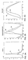
- FIG. 3A shows a typical pressure curve for an early combustion center position by reference numeral 31 and a pressure curve of a late combustion center of gravity position by reference numeral 32.
- Such pressure profiles can be determined, for example, from design data of the internal combustion engine 1.
- Fig. 3B shows the corresponding gas exchange moments M ⁇ gas early with reference numerals 33 and M ⁇ gas Late with reference numeral 34.
- Fig. 3C are shown from the combustion resulting on one normalized portions of the speed curves for the early combustion center position (reference numeral 35) and for the late combustion centroid position (reference numeral 36).
- Fig. 4 shows the normalized from the oscillating masses for a whole working cycle speed component, which results from the integral on the derivative of the moment of inertia ⁇ '.
- equation (14) can now be used instead of the Fourier series as matrix A in the further calculations according to equations (5) - (11).
- the speed model according to equation (14) can additionally be combined with a Fourier series according to equation (3) for the fundamental frequency and first and second order frequencies in order to assess nonuniformities of the individual cylinder segments in a working cycle.
- the previously described methods for determining and correcting the sensor wheel error can be further improved by determining the tooth errors not on the basis of the measured rotational speed, the so-called raw rotational speed, but on the basis of a mass-force-corrected rotational speed.
- the mass force correction is determined on the basis of the gas exchange torque as described above in connection with equation (12).
- the second term 1 2 ⁇ ⁇ ' ⁇ ⁇ 2 describes the proportion of moments, which is caused by the oscillating inertial forces, such as pistons and connecting rods. To this proportion, the raw speed is now corrected, so that in the resulting mass-force-corrected speed only from the Combustion-based forces and accelerations are included. For the sake of simplicity, it is assumed that a medium rotational speed ⁇ via a working cycle, so that in the following integration, the rotational speed can be regarded as constant.
- the equation (12) of the gas exchange torque is then converted into a speed equation by dividing by the moment of inertia ⁇ and then integrating both sides of the equation.
- the left side of the equation thus describes the proportion of the speed curve caused by the combustion.
- the correction term for correcting the measured raw rotational speed is thus determined from the second term of the right-hand side.
- n gas n ⁇ 1 + 1 2 ⁇ ln ⁇ - ln ⁇ ⁇
- the correction term can be determined in advance for a working cycle from design data of the internal combustion engine 1 and stored in the device 5.
- Fig. 5 shows by way of example the course of the correction term of the equation (20) for a working cycle of a four-cylinder engine. Since the curves over the cylinder segments are periodic and the curve is symmetrical in a cylinder segment, the number of coefficients to be stored of the correction term can be reduced and the calculation during operation of the internal combustion engine can be reduced to a few multiplications and additions.
- the moment of inertia can be determined from constructional data of the respective internal combustion engine. This calculation includes all rotating moments of inertia and all oscillating masses. Components, such as the connecting rods, are divided into a rotating and an oscillating component, wherein the rotating component with the approximation ⁇ ⁇ m ⁇ r 2 is determined with the crank radius r.
Landscapes
- Engineering & Computer Science (AREA)
- Chemical & Material Sciences (AREA)
- Combustion & Propulsion (AREA)
- Mechanical Engineering (AREA)
- General Engineering & Computer Science (AREA)
- Physics & Mathematics (AREA)
- General Physics & Mathematics (AREA)
- Combined Controls Of Internal Combustion Engines (AREA)
Abstract
Die vorliegende Erfindung betrifft ein Verfahren zur automatischen Bestimmung eines Geberradfehlers (Δϕ) einer Brennkraftmaschine (1). Die Brennkraftmaschine (1) umfasst ein an einer Welle (2) angebrachtes Geberrad (3) und einen Geberradsensor (4). Der Geberradsensor ist in der Lage, mehrere vorbestimmte Drehwinkel der Welle (2) zu erfassen. Bei dem Verfahren wird ein Drehzahlmodell bereitgestellt, welches für mehrere vorbestimmte Drehwinkel eines Arbeitsspiels der Brennkraftmaschine (1) jeweils eine Modelldrehzahl (ϕ̇Modell) bereitstellt. Für mehrere der vorbestimmten Drehwinkel des Arbeitsspiels wird mit Hilfe des Geberrades (3) und des Geberradsensors (4) eine jeweilige Drehzahl (ϕ̇gemessen) bestimmt. Aus dem Drehzahlmodell, den erfassten Drehzahlen (ϕ̇gemessen) und der Bedingung, dass die Summe über alle bestimmten Geberradfehler (Δϕ) näherungsweise null ist, wird der Geberradfehler (Δϕ) für mindestens einen der vorbestimmten Drehwinkel des Arbeitsspiels bestimmt.

Description
Die vorliegende Erfindung betrifft ein Verfahren zur automatischen Bestimmung eines Geberradfehlers einer Brennkraftmaschine und eine entsprechende Vorrichtung zur Bestimmung des Geberradfehlers der Brennkraftmaschine.The present invention relates to a method for the automatic determination of a Geberradfehlers an internal combustion engine and a corresponding device for determining the Geberradfehlers the internal combustion engine.
Bei der Drehzahlerfassung und Drehwinkelerfassung an Brennkraftmaschinen, insbesondere an Brennkraftmaschinen von Fahrzeugen, wie z.B. Personenkraftwagen oder Lastkraftwagen, werden sogenannte Geberräder verwendet. Die Geberräder können beispielsweise an einer Kurbelwelle oder einer Nockenwelle der Brennkraftmaschine angebracht sein. Die Geberräder können mit Markierungen, wie z.B. Zähnen, versehen sein, welche mittels eines feststehenden Messaufnehmers oder Sensors abgetastet werden. Vorzugsweise weist das Geberrad an seinem Umfang gleichmäßig verteilt eine vorbestimmte Anzahl von Zähnen auf. Zur Bestimmung der absoluten Position des Geberrades können an einer vorbestimmten Stelle des Geberrades ein oder mehrere Zähne weggelassen werden. Dabei werden in dem Messaufnehmer, beispielsweise einem induktiven Sensor, von den vorbeilaufenden Markierungen Spannungsimpulse induziert und in einer nachfolgenden Auswerteschaltung wird aus den zeitlichen Abständen dieser Spannungsimpulse die Drehzahl oder die Winkelgeschwindigkeit der Welle ermittelt. Je genauer die Erfassung des Drehwinkels von beispielsweise der Kurbelwelle der Brennkraftmaschine sowie der Drehzahl derselben am Geberrad erfasst werden kann, desto genauer kann ein Regelverfahren eines Regelkreises zur Steuerung der Brennkraftmaschine arbeiten.In the speed detection and angle detection on internal combustion engines, in particular on internal combustion engines of vehicles, such. Passenger cars or trucks, so-called donor wheels are used. The encoder wheels can be mounted, for example, on a crankshaft or a camshaft of the internal combustion engine. The encoder wheels may be provided with markings such as e.g. Teeth be provided, which are scanned by means of a fixed sensor or sensor. Preferably, the sender wheel has a predetermined number of teeth evenly distributed on its circumference. To determine the absolute position of the encoder wheel one or more teeth may be omitted at a predetermined location of the encoder wheel. In this case, voltage pulses are induced in the sensor, for example an inductive sensor, by the passing markers, and in a subsequent evaluation circuit, the rotational speed or the angular velocity of the shaft is determined from the time intervals of these voltage pulses. The more accurate the detection of the angle of rotation of, for example, the crankshaft of the internal combustion engine and the rotational speed of the same can be detected at the encoder wheel, the more accurate a control method of a control loop for controlling the internal combustion engine can work.
Die Drehzahl- und Winkelwerte können jedoch durch Toleranzeinflüsse verfälscht werden. Zu solchen Toleranzeinflüssen zählen beispielsweise Teilungsfehler am Geberrad, ein Anbaufehler des Messaufnehmers oder des Geberrades an der Stirnseite der Kurbelwelle, sowie Toleranzen des Messaufnehmers. Dadurch können einzelne Winkel zwischen zwei Zähnen vom Idealwert erheblich abweichen. In dem Stand der Technik sind daher verschiedene Ansätze bekannt, um den Geberradfehler zu bestimmen oder Auswirkungen des Geberradfehlers zu kompensieren.However, the speed and angle values can be falsified by tolerance influences. Such tolerance influences include, for example, pitch errors on the encoder wheel, a mounting error of the sensor or the sensor wheel on the front side of the crankshaft, and tolerances of the sensor. As a result, individual angles between two teeth can deviate significantly from the ideal value. In the prior art, therefore, various approaches are known to determine the encoder wheel error or compensate for effects of the Geberradfehlers.
Die
Die
Die
Die
Die
Die
Die
Die
Die
Die
Die
Die
Die
Die in dem Stand der Technik bekannten Verfahren weisen eine begrenzte Genauigkeit auf und erfordern zum Teil einen erheblichen Rechenaufwand, welcher im laufenden Betrieb der Brennkraftmaschine aufzuwenden ist.The methods known in the prior art have a limited accuracy and sometimes require a considerable amount of computation, which is spent during operation of the internal combustion engine.
Aufgabe der vorliegenden Erfindung ist es daher, eine möglichst genaue Bestimmung eines Geberradfehlers einer Brennkraftmaschine zu ermöglichen, welche im Betrieb der Brennkraftmaschine einfach und somit schnell und kostengünstig durchführbar ist.Object of the present invention is therefore to enable the most accurate determination of a Geberradfehlers an internal combustion engine, which is simple and thus quickly and inexpensively feasible during operation of the internal combustion engine.
Gemäß der vorliegenden Erfindung wird diese Aufgabe durch ein Verfahren zur automatischen Bestimmung eines Geberradfehlers einer Brennkraftmaschine nach Anspruch 1, eine Vorrichtung zur Bestimmung eines Geberradfehlers einer Brennkraftmaschine nach Anspruch 10 und nach Anspruch 12 und ein Fahrzeug nach Anspruch 14 gelöst. Die abhängigen Ansprüche definieren bevorzugte und vorteilhafte Ausführungsformen der Erfindung.According to the present invention, this object is achieved by a method for automatically determining a Geberradfehlers an internal combustion engine according to
Gemäß der vorliegenden Erfindung wird ein Verfahren zu automatischen Bestimmung eines Geberradfehlers einer Brennkraftmaschine bereitgestellt. Die Brennkraftmaschine weist ein Geberrad und einen Geberradsensor auf. Das Geberrad ist an einer Welle der Brennkraftmaschine angebracht. Der Geberradsensor ist mit Hilfe des Geberrades in der Lage, mehrere vorbestimmte Drehwinkel der Welle zu erfassen. Bei dem Verfahren wird ein Drehzahlmodell der Brennkraftmaschine bereitgestellt, welches für mehrere vorbestimmte Drehwinkel eines Arbeitsspiels der Brennkraftmaschine jeweils eine Modelldrehzahl bereitstellt. Weiterhin wird für mehrere der vorbestimmten Drehwinkel des Arbeitsspiels mittels des Geberrads und des Geberradsensors eine jeweilige Drehzahl bestimmt. Aus dem Drehzahlmodell, den erfassten Drehzahlen für die mehreren vorbestimmten Winkel des Arbeitsspiels und der Bedingung, dass die Summe über alle bestimmten Geberradfehler einer Umdrehung null ist, wird der Geberradfehler für mindestens einen der vorbestimmten Drehwinkel des Arbeitsspiels bestimmt.According to the present invention, a method of automatically determining a sensor wheel error of an internal combustion engine is provided. The internal combustion engine has a transmitter wheel and a transmitter wheel sensor. The sender wheel is attached to a shaft of the internal combustion engine. The sensor wheel sensor is able to detect a plurality of predetermined rotational angles of the shaft with the aid of the encoder wheel. In the method, a speed model of the internal combustion engine is provided, which in each case provides a model speed for a plurality of predetermined rotational angles of a working cycle of the internal combustion engine. Furthermore, a respective speed is determined for several of the predetermined rotation angle of the working cycle by means of the encoder wheel and the encoder wheel. From the speed model, the detected speeds for the plurality of predetermined operating cycle angles, and the condition that the sum over all particular encoder wheel errors of one revolution be zero, the encoder wheel error is determined for at least one of the predetermined operating cycle rotational angles.
Das Geberrad kann beispielsweise an einer Kurbelwelle der Brennkraftmaschine angebracht sein und entlang seines Umfangs mit Zähnen versehen sein. Der Geberradsensor kann beispielweise derart ausgestaltet sein, dass er induktiv, optisch oder unter Verwendung des Hall-Effekts elektrische Signale bereitstellt, welche mit an dem Geberradsensor vorbeilaufenden Zähnen des Geberrades korrespondieren.The sender wheel may for example be attached to a crankshaft of the internal combustion engine and be provided with teeth along its circumference. The sensor wheel sensor can be designed, for example, such that it provides electrical signals inductively, optically or using the Hall effect, which signals correspond to teeth of the sensor wheel passing by the sensor wheel sensor.
Indem das Drehzahlmodell für die mehreren vorbestimmten Drehwinkel eines Arbeitsspiels der Brennkraftmaschine jeweils eine entsprechende Modelldrehzahl bereitstellt, kann durch in Bezug setzen der Modelldrehzahlen und der mit Hilfe des Geberrads und des Geberradsensors bestimmten tatsächlichen Drehzahlen ein Geberradfehler bestimmt werden. Mit der zusätzlichen Bedingung, dass die Summe über alle Geberradfehler null ist, d.h., dass die Summe aller Geberradfehler für alle vorbestimmten Drehwinkel null ist, können Ungenauigkeiten des Drehzahlmodells ausgeglichen werden und die Genauigkeit des bestimmten Geberradfehlers erhöht werden.By the speed model for the several predetermined rotation angle of a working cycle of the internal combustion engine each provides a corresponding model speed can be determined by relating the model speeds and the determined using the encoder wheel and the encoder wheel actual speeds a Geberradfehler. With the additional condition that the sum over all encoder wheel errors is zero, i.e., that the sum of all encoder wheel errors is zero for all predetermined rotation angles, inaccuracies of the speed model can be compensated and the accuracy of the particular sensor wheel error increased.
Gemäß einer Ausführungsform werden mit Hilfe des Drehzahlmodells mehrere Koeffizienten, sogenannte Filterkoeffizienten, derart bestimmt, dass der Geberradfehler für einen vorbestimmten Drehwinkel bestimmt wird, indem eine mit den Koeffizienten gewichtete Summe der erfassten Drehzahlen bestimmt wird. Die mehreren Koeffizienten können beispielsweise während einer Entwicklung oder Fertigung der Brennkraftmaschine bestimmt werden und die mit den Koeffizienten gewichtete Summe kann während eines Betriebs der Brennkraftmaschine bestimmt werden. Dadurch sind während des Betriebs der Brennkraftmaschine nur einfache arithmetische Operationen zur Bestimmung des Geberradfehlers notwendig, so dass der Geberradfehler im Betrieb der Brennkraftmaschine mit einer kostengünstigen Recheneinheit einfach und genau bestimmt werden kann.According to one embodiment, with the aid of the speed model, a plurality of coefficients, so-called filter coefficients, are determined such that the transmitter wheel error is determined for a predetermined rotation angle by determining a sum of the detected speeds weighted by the coefficients. The plurality of coefficients may be determined, for example, during engine development or manufacture, and the sum weighted with the coefficients may be determined during operation of the internal combustion engine. As a result, during operation of the internal combustion engine only simple arithmetic operations for determining the Geberradfehlers necessary so that the Geberradfehler can be easily and accurately determined during operation of the internal combustion engine with a cost-effective computing unit.
Gemäß einer weiteren Ausführungsform werden für mehrere Geberradfehler für mehrere der vorbestimmten Drehwinkel des Arbeitsspiels jeweils die mehreren Koeffizienten bestimmt und eine Symmetrieeigenschaft der Koeffizienten untereinander derart ausgenutzt, dass nur nicht redundante Koeffizienten zur Verwendung während des Betriebs der Brennkraftmaschine in der Recheneinheit gespeichert werden. In Abhängigkeit von dem verwendeten Drehzahlmodell, wovon nachfolgend einige Ausführungsformen beschrieben werden, können die Koeffizienten für die unterschiedlichen Geberradfehler für die unterschiedlichen Drehwinkel des Arbeitsspiels gewisse Symmetrieeigenschaften aufweisen. Da die Koeffizienten bereits bei der Entwicklung oder Fertigung der Brennkraftmaschine bestimmt werden können, können diese Symmetrieeigenschaften zur platzsparenden Speicherung der Koeffizienten verwendet werden. Dadurch kann Speicherplatz in der Recheneinheit von einer Motorelektronik, welche die Geberradfehler zur Laufzeit der Brennkraftmaschine mit Hilfe der Koeffizienten bestimmt, eingespart werden.According to a further embodiment, the plurality of coefficients are determined for a plurality of encoder wheel errors for a plurality of the predetermined rotational angles of the working cycle and a symmetry property of the coefficients is utilized in such a way that only non-redundant coefficients for use during operation of the internal combustion engine are stored in the arithmetic unit. Depending on the speed model used, some of which are described below, the coefficients for the different encoder wheel errors for the different rotational angles of the working cycle may have certain symmetry properties. Since the coefficients can already be determined during the development or production of the internal combustion engine, these symmetry properties can be used for space-saving storage of the coefficients. This space in the arithmetic unit of an engine electronics, which the Transmitter wheel error determined at runtime of the internal combustion engine using the coefficients can be saved.
Gemäß einer weiteren Ausführungsform werden die jeweiligen Modelldrehzahlen für einen jeweiligen vorbestimmten Drehwinkel des Arbeitsspiels jeweils als eine Teilsumme einer Fourier-Reihe modelliert. Die Grundfrequenz der Fourier-Reihe entspricht dabei der Frequenz des Arbeitsspiels der Brennkraftmaschine. Die Teilsumme der Fourier-Reihe kann beispielsweise Polynome der Grundfrequenz, der doppelten Grundfrequenz, der dreifachen Grundfrequenz, der vierfachen Grundfrequenz und/oder der achtfachen Grundfrequenz umfassen. Bei einer Viertaktbrennkraftmaschine hat das Arbeitsspiel einen Kurbelwellenwinkel von 720 Grad und entspricht der Grundfrequenz der Fourier-Reihe. Die doppelte Grundfrequenz entspricht somit einem Kurbelwellenwinkel von 360 Grad, die vierfache Grundfrequenz einem Kurbelwellenwinkel von 180 Grad und die achtfache Grundfrequenz einem Kurbelwellenwinkel von 90 Grad. Somit umfasst die Fourier-Reihe bei einem Vierzylindermotor Frequenzkomponenten bis zur doppelten Zündfrequenz. Alle darüber hinausgehenden Frequenzen werden als Komponenten angesehen, welche nicht durch die Drehung der Brennkraftmaschine verursacht werden, sondern durch die Geberradfehler bedingt sind.According to another embodiment, the respective model rotational speeds for a respective predetermined rotational angle of the working cycle are each modeled as a partial sum of a Fourier series. The fundamental frequency of the Fourier series corresponds to the frequency of the working cycle of the internal combustion engine. The subtotal of the Fourier series may comprise, for example, polynomials of the fundamental frequency, the double fundamental frequency, the triple fundamental frequency, the quadruple fundamental frequency and / or the eightfold fundamental frequency. In a four-stroke internal combustion engine, the working cycle has a crankshaft angle of 720 degrees and corresponds to the fundamental frequency of the Fourier series. The double fundamental frequency thus corresponds to a crankshaft angle of 360 degrees, four times the fundamental frequency of a crankshaft angle of 180 degrees and eight times the fundamental frequency of a crankshaft angle of 90 degrees. Thus, the Fourier series in a four-cylinder engine frequency components up to twice the ignition frequency. All frequencies beyond are considered as components which are not caused by the rotation of the internal combustion engine but are caused by the encoder wheel errors.
Gemäß einer weiteren Ausführungsform wird die jeweilige Modelldrehzahl für einen jeweiligen vorbestimmten Drehwinkel des Arbeitsspiels mit Hilfe eines physikalischen Modells auf der Grundlage eines Druckverlaufs in einem Zylinder der Brennkraftmaschine bestimmt. Ein derartiges physikalisches Modell kann beispielsweise die Drehzahl direkt aus dem Verbrennungsdruck bestimmen, indem aus dem Verbrennungsdruck eine Kraft auf die Kolben der Brennkraftmaschine und daraus mit Hilfe der Kurbelkinematik ein Moment an der Kurbelwelle bestimmt wird. Aus dem Moment kann die Winkelbeschleunigung der Kurbelwelle und daraus eine Drehzahl der Kurbelwelle bestimmt werden. Zur Vereinfachung kann auch auf der Grundlage des Gaswechselmoments ein entsprechendes physikalisches Drehzahlmodell bestimmt werden, aus welchem wie zuvor beschrieben Koeffizienten bestimmt werden können, die während des Betriebs der Brennkraftmaschine eine Bestimmung des Geberradfehlers über eine mit den Koeffizienten gewichtete Summe der erfassten Drehzahlen ermöglicht.According to another embodiment, the respective model speed for a respective predetermined rotational angle of the working cycle is determined by means of a physical model on the basis of a pressure curve in a cylinder of the internal combustion engine. Such a physical model can, for example, determine the rotational speed directly from the combustion pressure by determining a force on the pistons of the internal combustion engine from the combustion pressure and, using crank kinematics, a torque on the crankshaft. From the moment the angular acceleration of the crankshaft and therefrom a speed of the crankshaft can be determined. For the sake of simplicity, a corresponding physical speed model can also be determined on the basis of the gas exchange torque, from which coefficients, as described above, can be determined during operation of the internal combustion engine to determine the encoder wheel error over a sum of the detected speeds weighted by the coefficients.
Ein Arbeitsspiel der Brennkraftmaschine kann beispielsweise bei einer Viertaktbrennkraftmaschine 720 Grad Kurbelwellenumdrehung umfassen. Das Geberrad kann beispielsweise derart ausgestaltet sein, dass vorbestimmte Drehwinkel der Kurbelwelle in einem 6 Grad-Raster erfasst werden können. Auf der Grundlage des Drehzahlmodells können beispielsweise 120 Koeffizienten bestimmt werden, welche zum Gewichten von 120 erfassten Drehzahlwerten verwendet werden, welche im 6 Grad-Raster während eines Arbeitsspiels von 720 Grad erfasst werden. Aufgrund der Symmetrieeigenschaft der Koeffizienten kann die Anzahl von 120 Koeffizienten beispielsweise bei Verwendung des zuvor beschriebenen Fourier-Reihen-Drehzahlmodells auf 31 Koeffizienten verringert werden, welche in geeigneter Art und Weise zum Gewichten der 120 erfassten Drehzahlen zum Bestimmen der Geberradfehler verwendet werden können.For example, a working cycle of the internal combustion engine may include 720 degrees of crankshaft revolution in a four-stroke internal combustion engine. The sender wheel may for example be designed such that predetermined rotational angle of the crankshaft can be detected in a 6 degree grid. For example, based on the speed model, 120 coefficients may be determined, which are used to weight 120 sensed speed values, which are in 6 degree increments during a working cycle of 720 degrees are detected. Due to the symmetry property of the coefficients, the number of 120 coefficients, for example using the Fourier series speed model described above, can be reduced to 31 coefficients, which can be suitably used to weight the 120 detected speeds to determine the encoder wheel errors.
Gemäß der vorliegenden Erfindung wird weiterhin eine Vorrichtung zur Bestimmung eines Geberradfehlers einer Brennkraftmaschine bereitgestellt. An einer Welle, beispielsweise einer Kurbelwelle, der Brennkraftmaschine ist ein Geberrad angebracht und die Brennkraftmaschine weist einen Geberradsensor auf, welcher mit Hilfe des Geberrades in der Lage ist, mehrere vorbestimmte Drehwinkel der Welle zu erfassen. Die Vorrichtung umfasst eine Verarbeitungseinheit, welche mit dem Geberradsensor gekoppelt ist und ausgestaltet ist, ein Drehzahlmodell bereitzustellen, welches für mehrere vorbestimmte Drehwinkel eines Arbeitsspiels der Brennkraftmaschine jeweils eine Modelldrehzahl bereitstellt. Die Verarbeitungseinheit ist weiterhin ausgestaltet, eine jeweilige Drehzahl für mehrere der vorbestimmten Drehwinkel des Arbeitsspiels mit Hilfe des Geberrads und des Geberradsensors zu bestimmen und den Geberradfehler für mindestens einen der vorbestimmten Drehwinkel des Arbeitsspiels aus dem Drehzahlmodell, den erfassten Drehzahlen für die mehreren vorbestimmten Winkel des Arbeitsspiels und der Bedingung, dass die Summe über alle bestimmten Geberradfehler null ist, zu bestimmen. Die Vorrichtung kann weiterhin derart ausgestaltet sein, dass sie das zuvor beschriebene Verfahren oder eine seiner Ausführungsformen ausführt und umfasst daher auch die zuvor beschriebenen Vorteile.According to the present invention, there is further provided an apparatus for determining an encoder wheel error of an internal combustion engine. On a shaft, such as a crankshaft, the internal combustion engine, a sensor wheel is mounted and the internal combustion engine has a Geberradsensor, which is by means of the encoder wheel in a position to detect a plurality of predetermined rotational angles of the shaft. The apparatus includes a processing unit coupled to the encoder wheel sensor and configured to provide a speed model that provides a model speed for a plurality of predetermined rotational angles of a working cycle of the internal combustion engine. The processing unit is further configured to determine a respective speed for a plurality of the predetermined rotational angles of the working cycle by means of the encoder wheel and the sensor wheel sensor and the Geberradfehler for at least one of the predetermined rotation angle of the working cycle from the speed model, the detected speeds for the plurality of predetermined angles of the working cycle and determining the condition that the sum over all particular encoder wheel errors is zero. The device may further be configured to carry out the method described above or one of its embodiments, and therefore also includes the advantages described above.
Erfindungsgemäß wird weiterhin eine Vorrichtung zur Bestimmung eines Geberradfehlers einer Brennkraftmaschine bereitgestellt, die eine Verarbeitungseinheit und einen Koeffizientenspeicher umfasst. Die Brennkraftmaschine weist ein an einer Welle der Brennkraftmaschine angebrachtes Geberrad und einen Geberradsensor auf und der Geberradsensor ist mit Hilfe des Geberrades in der Lage, mehrere vorbestimmte Drehwinkel der Welle zu erfassen. In dem Koeffizientenspeicher sind mehrere Koeffizienten gespeichert, welche mit Hilfe eines Drehzahlmodells der Brennkraftmaschine und der Bedingung, dass die Summe über alle Geberradfehler einer Umdrehung der Brennkraftmaschine null ist, bestimmt wurden. Das Drehzahlmodell stellt für mehrere vorbestimmte Drehwinkel des Arbeitsspiels jeweils eine Modelldrehzahl bereit. Die Verarbeitungseinheit ist mit dem Geberradsensor und dem Koeffizientenspeicher gekoppelt und ausgestaltet, für mehrere der vorbestimmten Drehwinkel des Arbeitsspiels jeweils eine Drehzahl mit Hilfe des Geberrads und des Geberradsensors zu bestimmen. Weiterhin ist die Verarbeitungseinheit ausgestaltet, den Geberradfehler für mindestens einen der vorbestimmten Drehwinkel des Arbeitsspiels mit Hilfe einer mit den Koeffizienten gewichteten Summe der erfassten Drehzahlen zu bestimmen. Weiterhin kann die Vorrichtung zur Durchführung des zuvor beschriebenen Verfahrens oder einer seiner Ausführungsformen ausgestaltet sein und umfasst daher die zuvor beschriebenen Vorteile.According to the invention, a device for determining a sensor wheel error of an internal combustion engine is further provided, which comprises a processing unit and a coefficient memory. The internal combustion engine has a transmitter wheel attached to a shaft of the internal combustion engine and a transmitter wheel sensor, and the transmitter wheel sensor is able to detect a plurality of predetermined rotational angles of the shaft with the aid of the transmitter wheel. In the coefficient memory, a plurality of coefficients are stored, which were determined by means of a speed model of the internal combustion engine and the condition that the sum over all encoder wheel errors of one revolution of the internal combustion engine is zero. The speed model provides a model speed for a plurality of predetermined rotational angles of the working cycle. The processing unit is coupled to the Geberradsensor and the coefficient memory and configured to determine a number of rotational speeds for each of the predetermined rotational angle of the working cycle with the aid of the encoder wheel and the Geberradsensors. Furthermore, the processing unit is configured to determine the encoder wheel error for at least one of the predetermined rotational angle of the working cycle by means of a weighted sum of the detected rotational speeds with the coefficients. Furthermore, the device may be designed to carry out the method described above or one of its embodiments, and therefore comprises the advantages described above.
Gemäß der vorliegenden Erfindung wird weiterhin ein System bereitgestellt, welches die zuvor beschriebene Vorrichtung und ein Entwicklungssystem umfasst. Das Entwicklungssystem ist ausgestaltet, mit Hilfe eines Drehzahlmodells, welches für mehrere vorbestimmte Drehwinkel eines Arbeitsspiels der Brennkraftmaschine jeweils eine Modelldrehzahl bereitstellt, und der Bedingung, dass die Summe über alle Geberradfehler null ist, die Koeffizienten für den Koeffizientenspeicher zu bestimmen. Über eine entsprechende Schnittstelle können die so bestimmen Koeffizienten in die zuvor beschriebene Vorrichtung übertragen werden, um dort im Betrieb der Brennkraftmaschine zur Bestimmung der Geberradfehler verwendet zu werden. Die Bestimmung der Koeffizienten mit Hilfe der Entwicklungsvorrichtung wird vorzugsweise während einer Entwicklung oder Fertigung der Brennkraftmaschine durchgeführt.According to the present invention, there is further provided a system comprising the apparatus and a development system described above. The development system is configured to determine the coefficients for the coefficient memory by means of a speed model which provides a model speed for a plurality of predetermined rotational angles of a working cycle of the internal combustion engine and the condition that the sum over all transmitter wheel errors is zero. Via a corresponding interface, the coefficients thus determined can be transferred to the device described above in order to be used there during the operation of the internal combustion engine for determining the encoder wheel errors. The determination of the coefficients by means of the developing device is preferably carried out during development or manufacture of the internal combustion engine.
Schließlich wird gemäß der vorliegenden Erfindung ein Fahrzeug mit einer der zuvor beschriebenen Vorrichtungen zur Bestimmung des Geberradfehlers der Brennkraftmaschine des Fahrzeugs bereitgestellt.Finally, according to the present invention, a vehicle is provided with one of the above-described devices for determining the Geberradfehlers the internal combustion engine of the vehicle.
Die vorliegende Erfindung wird nachfolgend unter Bezugnahme auf die beigefügten Zeichnungen anhand bevorzugter Ausführungsformen erläutert werden.
-
Fig. 1 zeigt schematisch eine Vorrichtung zur Bestimmung eines Geberradfehlers einer Brennkraftmaschine gemäß einer Ausführungsform der vorliegenden Erfindung. -
Fig. 2 zeigt Koeffizientenwerte zum Bestimmen eines Geberradfehlers, welche gemäß einer Ausführungsform des Verfahrens der vorliegenden Erfindung bestimmt wurden. -
Fig. 3 zeigt schematisch einen Druckverlauf in einem Zylinder der Brennkraftmaschine, ein sich daraus ergebendes Gaswechselmoment und eine sich daraus ergebende normierte Drehzahl, welche für ein physikalisches Modell verwendet werden, um einen Geberradfehler gemäß der vorliegenden Erfindung zu bestimmen. -
Fig. 4 zeigt ein normiertes Trägheitsmoment abgeleitet nach dem Kurbelwellenwinkel aus oszillierenden Massen für ein ganzes Arbeitsspiel einer Brennkraftmaschine, welches in einem physikalischen Modell zur Bestimmung eines Geberradfehlers gemäß einem Verfahren der vorliegenden Erfindung verwendet wird. -
Fig. 5 zeigt Werte zur Korrektur von Rohdrehzahlwerten auf der Grundlage einer Massen-Kraftkorrektur, wobei die Massen-Kraft-korrigierte Drehzahl bei einem Verfahren zur Bestimmung eines Geberradfehlers gemäß einer Ausführungsform der vorliegenden Erfindung verwendet werden kann.
-
Fig. 1 schematically shows an apparatus for determining a Geberradfehlers an internal combustion engine according to an embodiment of the present invention. -
Fig. 2 shows coefficient values for determining a sensor wheel error determined according to an embodiment of the method of the present invention. -
Fig. 3 12 schematically shows a pressure curve in a cylinder of the internal combustion engine, a resulting gas exchange torque and a resulting normalized speed, which are used for a physical model to determine a sensor wheel error according to the present invention. -
Fig. 4 FIG. 12 shows a normalized moment of inertia derived from the crankshaft angle of oscillating masses for a whole cycle of an internal combustion engine used in a physical model for determining a sensor wheel error according to a method of the present invention. -
Fig. 5 shows values for correcting raw speed values based on a mass force correction, wherein the mass force corrected speed may be used in a method for determining a sensor wheel error according to an embodiment of the present invention.
Aufgrund von mechanischen Toleranzen des Geberrades 3, beispielsweise Teilungsfehlern der Zähne des Geberrads 3 oder Anbaufehler des Geberrads 3 an der Welle 2, können Winkelpositionen, Winkelgeschwindigkeiten und Drehzahlen der Welle 2, welche mit Hilfe des Geberradsensors 4 erfasst und der Vorrichtung 5 bestimmt werden, Toleranzen oder Verfälschungen aufweisen. Zum Korrigieren der über einen Zahn des Geberrades 3 bestimmten Drehzahl bzw. Winkelgeschwindigkeit ist die gemessene Winkelgeschwindigkeit ϕ̇gemessen gemäß der nachfolgenden Gleichung (1) mit dem Geberradfehler Δϕ des entsprechenden Geberads 3 zu korrigieren, woraus sich die korrigierte Winkelgeschwindigkeit ϕ̇ korrigiert ergibt: 
Um den Fehler Δϕ eines Zahns des Geberrads 3 zu bestimmen, wird die korrigierte Drehzahl ϕ̇korrigiert durch eine Modelldrehzahl ϕ̇Modell ersetzt, welche aus einem Drehzahlmodell für die Brennkraftmaschine 1 für den vorbestimmten Drehwinkel, an dem sich der entsprechende Zahn befindet, eine entsprechende Modelldrehzahl bereitstellt. Aus Vereinfachungsgründen wird weiterhin für den Korrekturterm Aϕ/6 eine mittlere Drehzahl ![]()

![]()
Gemäß einer ersten Ausführungsform wird für die Modelldrehzahl eine Fourier-Reihe angesetzt. Unter der Annahme einer Brennkraftmaschine, welche nach dem Viertaktprinzip arbeitet, ergibt sich für die Fourier-Reihe eine Grundfrequenz von 1/720 Grad Kurbelwellenwinkel, d.h., dass sich ein Arbeitsspiel der Brennkraftmaschine 1 nach zwei Umdrehungen der Kurbelwelle wiederholt. Die allgemeine Darstellung der Fourier-Reihe für die Modelldrehzahl ϕ̇Modell zeigt die nachfolgende Gleichung (3): 
Die Koeffizienten A0, Ak und Bk sind jedoch im Allgemeinen nicht bekannt. Aufgrund der Arbeitsweise der Brennkraftmaschine 1 (Viertaktprinzip) und der bekannten Anzahl der Zylinder der Brennkraftmaschine 1, beispielsweise vier Zylinder, können jedoch Annahmen über relevante Oberwellenanteile der Modelldrehzahl ϕ̇Modell getroffen werden. Bei einem Vierzylindermotor sind beispielsweise Oberwellen bis zur doppelten Zündfrequenz signifikant, d.h., die Terme der Gleichung (3) für k=1, 2, 3, 4 und 8 sind von besonderer Relevanz. Dadurch kann die Reihenentwicklung der Gleichung (3) entsprechend vereinfacht werden.However, the coefficients A 0 , A k and B k are generally unknown. Due to the operation of the internal combustion engine 1 (four-stroke principle) and the known number of cylinders of the
Bei dem oben angenommenen Geberrad mit 6 Grad-Teilung ergibt sich für das oben genannte 720 Grad-Arbeitsspiel für die Modelldrehzahl ϕ̇ für jeden Zahn folgende Gleichung (4): 
welches mit den entsprechenden Vektoren b und x und der Matrix A der Gleichung (4a) entspricht: 
which corresponds to the corresponding vectors b and x and the matrix A of the equation (4a):
Durch Einsetzen der Gleichungen (4) in die Gleichung (2) und zusätzlicher Einbeziehung einer Nebenbedingung ergibt sich die nachfolgende Gleichung (5): 
Dabei ist Φ̇gemessen ein Vektor der gemessenen Drehzahlen ϕ̇gemessen für jeden Zahn des Geberrads 3, A die mittlere Matrix der Gleichung (4), G eine Diagonalmatrix mit dem Term ― ![]()
![]()
Um das Gleichungssystem der Gleichung (5) in der Vorrichtung 5, beispielsweise einem Steuergerät der Brennkraftmaschine 1, zu berechnen, sind ein erheblicher Speicherplatz und eine erhebliche Rechenleistung erforderlich, welche in üblichen Steuergeräten nicht verfügbar sind. Indem das Gleichungssystem (5) durch ![]()
![]()

![]()
![]()
Gleichung (7) zeigt den Aufbau der Matrix Rinv: 
Die ersten Zeilen Rx der Matrix Rinv gehören zur Berechnung der Fourier-Koeffizienten Ak, Bk (skaliert mit ![]()
![]()
Somit wird der Geberradfehler ΔΦ über ein Skalarprodukt mit 120 Koeffizienten (RΔΦ) der gemessenen Drehzahlen (Φ̇gemessen) berechnet, wie in Gleichung (8) dargestellt: 
Zu einem Zahn des Geberrads 3 gehört dabei immer eine Zeile der Matrix RΔϕ. Dabei sind die Koeffizienten für alle Zahnfehler gleich, allerdings jeweils um eine Stelle gegenüber dem vorhergehenden Zahn verschoben. Daher ist es ausreichend, 120 verschiedene Koeffizienten für alle Zahnfehler zu speichern, welche dann in geeigneter Art und Weise zur Bestimmung der jeweiligen Zahnfehler verwendet werden. Darüber hinaus sind die Koeffizienten in großen Teilen symmetrisch, so dass man bei genauerer Betrachtung sogar nur 31 unterschiedliche Koeffizienten in dem Koeffizientenspeicher 7 der Vorrichtung 5 benötigt.
Jeder auf die zuvor beschriebene Art und Weise bestimmte Zahnfehler für einen Zahn des Geberrads 3 wird über mehrere Arbeitsspiele der Brennkraftmaschine 1 bestimmt und beispielsweise mit Hilfe eines sogenannten PT1-Filters mit einem Lernfaktor w gemäß der nachfolgenden Gleichungen (9) und (10) weiter verbessert, wobei k die zur Iteration verwendeten Arbeitsspiele zählt. 
![]()
![]()
Die so bestimmten Zahnfilter Δϕk können dann gemäß Gleichung (11) verwendet werden, um aus der gemessenen Drehzahl ϕ̇gemessen die eigentliche Drehzahl ϕ̇k des Zahns k zu bestimmen. 
Für eine effiziente Berechnung in der Vorrichtung 5 wird die Division durch 6 vorzugsweise schon in den Filterkoeffizienten vorgenommen. Somit sind in der Vorrichtung 5 neben der Division durch die mittlere Drehzahl ![]()
![]()
![]()
![]()
Gemäß einer weiteren Ausführungsform kann das Drehzahlmodell der Brennkraftmaschine 1 statt auf der zuvor beschriebenen Fourier-Reihe alternativ auf einem physikalischen Ansatz beruhen. Grundlage dafür ist eine Berechnung der Drehzahl direkt aus dem Verbrennungsdruck, indem aus dem Druck eine Kraft auf die Kolben bestimmt wird und daraus zusammen mit der Kurbelkinematik ein Moment auf die Welle 2 bestimmt wird. Aufgrund des Moments wird die Winkelbeschleunigung der Welle 2 und daraus die Drehzahl ermittelt. Da eine Berechnung der Drehzahl aus dem Verbrennungsdruck jedoch verhältnismäßig aufwändig ist und daher in üblichen Steuergeräten nicht in Echtzeit durchführbar ist, werden folgende Vereinfachungen durchgeführt, um das Drehzahlmodell im Wesentlichen auf Linearkombinationen von Funktionen zu reduzieren.According to a further embodiment, the speed model of the
Die Drehzahl setzt sich prinzipiell aus drei Anteilen zusammen, die aus der Verbrennungskraft und aus dem Trägheitsmoment der oszillierenden Massen, wie z.B. der Kolben und Pleuel, stammen. Gleichung (12) beschreibt das sogenannte Gaswechselmoment und verdeutlicht diesen Zusammenhang: 
![]()

wobei K1 und K2 über die gemessene Drehzahl zu schätzende Faktoren sind, in denen unter anderem das Reziproke des Trägheitsmoments (in K1 und K2) und das Quadrat der mittleren Drehzahl (in K2) eingehen. Mit K3 wird ein Offset geschätzt. Mit der Modellfunktion nach Gleichung (13) kann eine theoretische stationäre Drehzahl sehr gut angenähert werden. Reale gemessene Drehzahlen sind jedoch nicht immer stationär und ändern ihre Phasenlage bedingt durch unterschiedliche Phasenlagen der Verbrennung, insbesondere bedingt durch die Verbrennungsschwerpunktlage α50. Um diese unterschiedlichen Phasenlagen zu berücksichtigen, wird der erste Term der Gleichung (13), der das Gaswechselmoment M̃Gas beinhaltet und maßgeblich durch die Verbrennung beeinflusst wird, in zwei Drehzahlmodellfunktionen aufgeteilt. Eine erste Drehzahlmodellfunktion wird für eine sehr frühe Verbrennungsschwerpunktlage bestimmt und eine zweite Drehzahlmodellfunktion wird für eine sehr späte Verbrennungsschwerpunktlage bestimmt. Darüber hinaus kann noch eine Anstiegsfunktion M mit aufgenommen werden, um einen linearen Anstieg oder einen linearen Abfall im Drehzahlverlauf innerhalb eines Arbeitsspiels mitzuschätzen. Daraus ergibt sich eine Drehzahlmodellfunktion gemäß Gleichung (14): 
![]()
where K 1 and K 2 are factors to be estimated over the measured speed, among other things, the reciprocal of the moment of inertia (in K 1 and K 2 ) and the square of the average speed (in K 2 ). With K 3 , an offset is estimated. With the model function according to equation (13), a theoretical stationary speed can be approximated very well. However, real measured speeds are not always stationary and change their phase position due to different phase angles of the combustion, in particular due to the combustion center of gravity α 50 . To account for these different phase angles, the first term of equation (13), which includes the gas exchange moment M gas and is significantly affected by the combustion, is split into two speed model functions. A first speed model function is determined for a very early center of gravity and a second speed model function is determined for a very late center of gravity. In addition, an increase function M can also be included in order to assess a linear increase or a linear decrease in the speed curve within a working cycle. This results in a speed model function according to equation (14):
Die Drehzahlmodellfunktion gemäß Gleichung (14) wird ähnlich wie bei dem zuvor beschriebenen Fourier-Reihenverfahren in eine entsprechende Matrixdarstellung für ein Arbeitsspiel der Brennkraftmaschine 1 vergleichbar zu Gleichung (4) überführt. Wie zuvor im Zusammenhang mit Gleichungen (5)-(8) beschrieben, können dann daraus für jeden Zahnfehler 120 Koeffizienten bestimmt werden, welche gemäß Gleichung (8) zur Bestimmung einzelner Zahnfehler oder aller Zahnfehler des Geberrads 3 verwendet werden können. Üblicherweise unterscheiden sich nun jedoch die Koeffizienten zwischen den einzelnen Zähnen, so dass für jeden Zahn 120 eigene Koeffizienten in dem Koeffizientenspeicher 7 abzulegen sind.The speed model function according to equation (14), similar to the previously described Fourier series method, is converted into a corresponding matrix representation for a working cycle of the
![]()
![]()
![]()
![]()
Wie zuvor beschrieben, kann die Modellfunktion nach Gleichung (14) nun anstelle der Fourier-Reihe als Matrix A in den weiteren Berechnungen gemäß der Gleichungen (5)-(11) verwendet werden. Darüber hinaus kann das Drehzahlmodell gemäß Gleichung (14) zusätzlich mit einer Fourier-Reihe gemäß Gleichung (3) für die Grundfrequenz und Frequenzen erster und zweiter Ordnung kombiniert werden, um Ungleichförmigkeiten der einzelnen Zylindersegmente in einem Arbeitsspiel mitzuschätzen.As described above, the model function of equation (14) can now be used instead of the Fourier series as matrix A in the further calculations according to equations (5) - (11). In addition, the speed model according to equation (14) can additionally be combined with a Fourier series according to equation (3) for the fundamental frequency and first and second order frequencies in order to assess nonuniformities of the individual cylinder segments in a working cycle.
Die zuvor beschriebenen Verfahren zur Bestimmung und Korrektur des Geberradfehlers können weiter verbessert werden, indem die Zahnfehler nicht auf der Grundlage der gemessenen Drehzahl, der sogenannten Rohdrehzahl, sondern auf der Grundlage einer Massen-Kraft-korrigierten Drehzahl bestimmt werden. Dadurch kann bei dem zuvor beschriebenen Fourier-Reiheverfahren auf Frequenzkomponenten über der Zündfrequenz hinaus verzichtet werden. Dies bedeutet für einen Vierzylindermotor beispielsweise, dass in der Fourier-Reihe nach Gleichung (3) nur noch Frequenzkomponenten für k=1...4 erforderlich sind, da die Massenkräfte keine drehzahlabhängigen Auswirkungen mehr zeigen.The previously described methods for determining and correcting the sensor wheel error can be further improved by determining the tooth errors not on the basis of the measured rotational speed, the so-called raw rotational speed, but on the basis of a mass-force-corrected rotational speed. As a result, in the previously described Fourier series method, frequency components above the ignition frequency can be dispensed with. This means for a four-cylinder engine, for example, that in the Fourier series according to equation (3) only frequency components for k = 1 ... 4 are required because the mass forces no longer show any speed-dependent effects.
Die Massen-Kraft-Korrektur wird auf der Grundlage des Gaswechselmoments, wie es im Zusammenhang mit Gleichung (12) zuvor beschrieben wurde, bestimmt. Der zweite Term ![]()

![]()
Die linke Seite der Gleichung beschreibt somit den Anteil am Drehzahlverlauf, der durch die Verbrennung hervorgerufen wird. Der Korrekturterm zur Korrektur der gemessenen Rohdrehzahl wird somit aus dem zweiten Term der rechten Seite bestimmt. Für das Integral des Korrekturterms ergibt sich nachfolgende Gleichung (16): 
Unter der Annahme einer konstanten Drehzahl kann dϕ/dt aus dem Integral herausgezogen werden und die rechte Seite der Gleichung (16) vereinfacht sich zu folgendem Term: 
Der folgende Term (18) stellte eine Lösung des unbestimmten Integrals des Terms (17) dar: 
Die Integrationskonstante C wird derart gewählt, dass der Term (18) mittelwertfrei bleibt, d.h.: 
Bei einem Vierzylindermotor ist der Korrekturterm periodisch in den Zylindersegmenten. Somit ergibt sich für die Massen-Kraft-Korrektur der Rohdrehzahl n folgende Gleichung (20): 
Der Korrekturterm kann für ein Arbeitsspiel vorab aus Konstruktionsdaten der Brennkraftmaschine 1 bestimmt werden und in der Vorrichtung 5 gespeichert werden.
Wie zuvor erwähnt, kann das Trägheitsmoment aus konstruktiven Daten der jeweiligen Brennkraftmaschine bestimmt werden. In diese Berechnung gehen alle rotierenden Trägheitsmomente und alle oszillierenden Massen ein. Komponenten, wie z.B. die Pleuel, werden in einen rotierenden und einen oszillierenden Anteil aufgeteilt, wobei der rotierende Anteil mit der Näherung Θ ≈m·r2 mit dem Kurbelradius r bestimmt wird. Das Trägheitsmoment der oszillierenden Massen ist dabei vom Kurbelwellenwinkel abhängig und berechnet sich nach Gleichung (21): ![]()
wobei x' ein Kolbengeschwindigkeitskennwert ist. Der Kolbengeschwindigkeitskennwert bildet die Winkelbeziehungen am Kurbeltrieb ab und ist ein Maß für die relative Kolbengeschwindigkeit: 

wobei ṡ die Kolbengeschwindigkeit, λ =r/l das Pleuelschlangenverhältnis und µ=d/l das Desachsierungsverhältnis ist.As mentioned above, the moment of inertia can be determined from constructional data of the respective internal combustion engine. This calculation includes all rotating moments of inertia and all oscillating masses. Components, such as the connecting rods, are divided into a rotating and an oscillating component, wherein the rotating component with the approximation Θ ≈m · r 2 is determined with the crank radius r. The moment of inertia of the oscillating masses is dependent on the crankshaft angle and is calculated according to equation (21): ![]()
where x 'is a piston speed characteristic. The piston speed characteristic depicts the angular relationships on the crank mechanism and is a measure of the relative piston speed:
where ṡ the piston speed, λ = r / l is the Pleuelschlangenverhältnis and μ = d / l is the Ausachsierungsverhältnis.
Obwohl die zuvor beschriebenen Ausführungsformen zur Bestimmung des Geberradfehlers 3 vollständig in der Verarbeitungseinheit 6 durchgeführt werden können, können ein Rechenleistungsbedarf und ein Speicherbedarf in der Vorrichtung 5 erheblich verringert werden, wenn lediglich die Koeffizienten der Matrix RΔΦ in dem Koeffizientenspeicher 7 abgelegt werden und nur die Berechnungen nach Gleichungen (8)-(11) in Echtzeit beim Betrieb der Brennkraftmaschine 1 mit der Verarbeitungseinheit 6 durchgeführt werden. Die zugrundeliegenden Berechnungen, beispielsweise nach Gleichungen (1)-(7) können vorzugsweise hingegen offline, d.h. beispielsweise während einer Entwicklung der Brennkraftmaschine 1 oder einer Erstinbetriebnahme der Brennkraftmaschine 1, durchgeführt werden und die sich daraus ergebenden Koeffizienten in den Koeffizientenspeicher 7 einmalig abgelegt werden. Dadurch können erhebliche Kosten für eine rechenstarke Verarbeitungseinheit 6 und einen großen Koeffizientenspeicher 7 eingespart werden.Although the above-described embodiments for determining the
Claims (14)
wobei die Verarbeitungseinheit (6) mit dem Geberradsensor (4) und dem Koeffizientenspeicher (7) gekoppelt ist und ausgestaltet ist,
wherein the processing unit (6) is coupled to the encoder wheel sensor (4) and the coefficient memory (7) and configured,
Applications Claiming Priority (1)
| Application Number | Priority Date | Filing Date | Title |
|---|---|---|---|
| DE201010054532 DE102010054532A1 (en) | 2010-12-15 | 2010-12-15 | Method for automatically determining a sensor wheel error of an internal combustion engine |
Publications (2)
| Publication Number | Publication Date |
|---|---|
| EP2492475A1 true EP2492475A1 (en) | 2012-08-29 |
| EP2492475B1 EP2492475B1 (en) | 2014-05-21 |
Family
ID=45062818
Family Applications (1)
| Application Number | Title | Priority Date | Filing Date |
|---|---|---|---|
| EP20110009289 Active EP2492475B1 (en) | 2010-12-15 | 2011-11-23 | Method for automatic detection of a rotary encoder error of a combustion engine |
Country Status (2)
| Country | Link |
|---|---|
| EP (1) | EP2492475B1 (en) |
| DE (1) | DE102010054532A1 (en) |
Families Citing this family (3)
| Publication number | Priority date | Publication date | Assignee | Title |
|---|---|---|---|---|
| DE202015003271U1 (en) * | 2015-05-04 | 2016-08-05 | GM Global Technology Operations LLC (n. d. Ges. d. Staates Delaware) | Computer program and computer program product Control of an internal combustion engine and internal combustion engine |
| DE102017209586A1 (en) * | 2017-06-07 | 2018-12-13 | Volkswagen Aktiengesellschaft | Apparatus and method for communicating a change in position of a signal transmitter wheel |
| DE102019212275A1 (en) | 2019-08-15 | 2021-02-18 | Volkswagen Aktiengesellschaft | Method for adapting a detected camshaft position, control unit for carrying out the method, internal combustion engine and vehicle |
Citations (17)
| Publication number | Priority date | Publication date | Assignee | Title |
|---|---|---|---|---|
| DE4216058A1 (en) * | 1992-05-15 | 1993-11-18 | Bosch Gmbh Robert | Correcting position of top dead centre reference marker in IC engine - using pressure variation measurement relating to crankshaft angle without combustion operation at different positions of marker and calculating pressure differences. |
| EP0696355B1 (en) | 1994-03-01 | 1998-08-19 | Robert Bosch Gmbh | Adaptation device for a sensor wheel on an internal combustion engine |
| DE19540674C2 (en) | 1995-10-31 | 1999-01-28 | Siemens Ag | Adaptation procedure for correcting tolerances of an encoder wheel |
| EP0929794B1 (en) | 1997-08-06 | 2002-11-27 | Robert Bosch Gmbh | Method and device for correcting margins of error of an indicating wheel |
| DE10217560A1 (en) | 2002-01-24 | 2004-04-22 | Fraunhofer-Gesellschaft zur Förderung der angewandten Forschung e.V. | Method for determining and compensating geometry errors of an encoder wheel |
| DE10246806A1 (en) | 2002-10-08 | 2004-04-22 | Daimlerchrysler Ag | Sender wheel for measuring crankshaft revolution rate, angle has variable widths of individual teeth for defined number of successive teeth, limited number of different widths over whole circumference |
| DE10318839B3 (en) | 2003-04-25 | 2004-06-03 | Siemens Ag | Correction value determination method for correction of measured segment time required for rotation of IC engine crankshaft through given angle |
| DE10256527A1 (en) | 2002-12-04 | 2004-06-24 | Robert Bosch Gmbh | Method for adapting angle errors of a phase signal of a phase sensor and system therefor |
| DE10123022B4 (en) | 2001-05-11 | 2005-06-23 | Siemens Ag | Speed detection method |
| DE10107892B4 (en) | 2001-02-16 | 2005-07-07 | Iav Gmbh Ingenieurgesellschaft Auto Und Verkehr | Method for identifying the encoder wheel error while driving |
| WO2005083252A1 (en) * | 2004-03-01 | 2005-09-09 | Robert Bosch Gmbh | Method and device for detecting the angular position signal in an internal combustion engine |
| US7194899B1 (en) * | 2006-05-29 | 2007-03-27 | Bo-Chiuan Chen | Method of estimating crack angles and rotation speeds of engine |
| DE102005047577A1 (en) | 2005-10-05 | 2007-04-12 | Robert Bosch Gmbh | Measuring crankshaft revolution rate involves controller determining crankshaft revolution rate from quotient of angle covered between two teeth on crankshaft and weighted mean tooth period |
| EP1272858B1 (en) | 2000-04-06 | 2007-10-10 | Robert Bosch Gmbh | Method for compensating the rotational shapelessness during detection of the revolutions per minute |
| FR2903448A1 (en) * | 2006-07-06 | 2008-01-11 | Renault Sas | METHOD FOR CONTROLLING A VEHICLE ENGINE BASED ON A MEASUREMENT OF AN ANGULAR POSITION OF A CRANKSHAFT |
| DE602004009400T2 (en) | 2004-01-31 | 2008-07-10 | Ford Global Technologies, LLC, Dearborn | Method for determining speed fluctuations of a motor |
| DE102008010102A1 (en) | 2008-02-20 | 2009-08-27 | Robert Bosch Gmbh | Method for adapting mechanical tolerances of a sensor wheel |
-
2010
- 2010-12-15 DE DE201010054532 patent/DE102010054532A1/en not_active Withdrawn
-
2011
- 2011-11-23 EP EP20110009289 patent/EP2492475B1/en active Active
Patent Citations (17)
| Publication number | Priority date | Publication date | Assignee | Title |
|---|---|---|---|---|
| DE4216058A1 (en) * | 1992-05-15 | 1993-11-18 | Bosch Gmbh Robert | Correcting position of top dead centre reference marker in IC engine - using pressure variation measurement relating to crankshaft angle without combustion operation at different positions of marker and calculating pressure differences. |
| EP0696355B1 (en) | 1994-03-01 | 1998-08-19 | Robert Bosch Gmbh | Adaptation device for a sensor wheel on an internal combustion engine |
| DE19540674C2 (en) | 1995-10-31 | 1999-01-28 | Siemens Ag | Adaptation procedure for correcting tolerances of an encoder wheel |
| EP0929794B1 (en) | 1997-08-06 | 2002-11-27 | Robert Bosch Gmbh | Method and device for correcting margins of error of an indicating wheel |
| EP1272858B1 (en) | 2000-04-06 | 2007-10-10 | Robert Bosch Gmbh | Method for compensating the rotational shapelessness during detection of the revolutions per minute |
| DE10107892B4 (en) | 2001-02-16 | 2005-07-07 | Iav Gmbh Ingenieurgesellschaft Auto Und Verkehr | Method for identifying the encoder wheel error while driving |
| DE10123022B4 (en) | 2001-05-11 | 2005-06-23 | Siemens Ag | Speed detection method |
| DE10217560A1 (en) | 2002-01-24 | 2004-04-22 | Fraunhofer-Gesellschaft zur Förderung der angewandten Forschung e.V. | Method for determining and compensating geometry errors of an encoder wheel |
| DE10246806A1 (en) | 2002-10-08 | 2004-04-22 | Daimlerchrysler Ag | Sender wheel for measuring crankshaft revolution rate, angle has variable widths of individual teeth for defined number of successive teeth, limited number of different widths over whole circumference |
| DE10256527A1 (en) | 2002-12-04 | 2004-06-24 | Robert Bosch Gmbh | Method for adapting angle errors of a phase signal of a phase sensor and system therefor |
| DE10318839B3 (en) | 2003-04-25 | 2004-06-03 | Siemens Ag | Correction value determination method for correction of measured segment time required for rotation of IC engine crankshaft through given angle |
| DE602004009400T2 (en) | 2004-01-31 | 2008-07-10 | Ford Global Technologies, LLC, Dearborn | Method for determining speed fluctuations of a motor |
| WO2005083252A1 (en) * | 2004-03-01 | 2005-09-09 | Robert Bosch Gmbh | Method and device for detecting the angular position signal in an internal combustion engine |
| DE102005047577A1 (en) | 2005-10-05 | 2007-04-12 | Robert Bosch Gmbh | Measuring crankshaft revolution rate involves controller determining crankshaft revolution rate from quotient of angle covered between two teeth on crankshaft and weighted mean tooth period |
| US7194899B1 (en) * | 2006-05-29 | 2007-03-27 | Bo-Chiuan Chen | Method of estimating crack angles and rotation speeds of engine |
| FR2903448A1 (en) * | 2006-07-06 | 2008-01-11 | Renault Sas | METHOD FOR CONTROLLING A VEHICLE ENGINE BASED ON A MEASUREMENT OF AN ANGULAR POSITION OF A CRANKSHAFT |
| DE102008010102A1 (en) | 2008-02-20 | 2009-08-27 | Robert Bosch Gmbh | Method for adapting mechanical tolerances of a sensor wheel |
Also Published As
| Publication number | Publication date |
|---|---|
| DE102010054532A1 (en) | 2012-06-21 |
| EP2492475B1 (en) | 2014-05-21 |
Similar Documents
| Publication | Publication Date | Title |
|---|---|---|
| EP0563347B1 (en) | Process for adapting mechanical tolerances of a pick-up wheel | |
| DE69617513T2 (en) | Nonlinear dynamic transformation to correct a crankshaft acceleration subject to torsional vibrations | |
| DE19540674C2 (en) | Adaptation procedure for correcting tolerances of an encoder wheel | |
| EP3080555B1 (en) | Device for and method of measuring a rotor parameter | |
| DE69410911T2 (en) | Device and method for compensating torsional disturbances in crankshafts | |
| EP0583495B1 (en) | Method for the detection and correction of errors in time measurements of rotating shafts | |
| DE69400200T2 (en) | Method and device for estimating a disturbance acting on a frosted vehicle wheel on the basis of the angular speed of the wheel | |
| EP1630363A1 (en) | Method to determine the phase of a camshaft in an internal combustion engine | |
| DE19514093A1 (en) | Torsional moment measuring device, slip detection device, road friction coefficient measuring device and torsional moment measuring method | |
| WO2013092398A2 (en) | Method and device for correcting a measured value of an angle of rotation of a rotor of an electric machine | |
| DE19622042C2 (en) | Method for recognizing and correcting errors in the time measurement on rotating shafts | |
| DE102019125755A1 (en) | Method for identifying interference components and device for identifying interference components | |
| EP2492475B1 (en) | Method for automatic detection of a rotary encoder error of a combustion engine | |
| WO1994010577A1 (en) | Device for determining engine speed gradient | |
| EP1723331B1 (en) | Method and device for detecting the angular position signal in an internal combustion engine | |
| DE3421640C2 (en) | ||
| EP1792057B1 (en) | Method for positional determination for an ec motor | |
| DE102005035881A1 (en) | Method for determining rotational angular position of camshaft of piston engine in relation to crankshaft entails extrapolating assessed value for rotational angle from adjusting shaft rotational angle measurements | |
| EP3464862A1 (en) | Method and apparatus for calibrating an actuator system | |
| EP2512859B1 (en) | Method for controlling an electric vehicle | |
| DE102019125730A1 (en) | Control device for a gear processing machine | |
| DE10217560B4 (en) | Method for determining and compensating geometrical errors of a rotary encoder wheel | |
| DE102013021218A1 (en) | Method for correcting faults caused by production-related mechanical tolerances of twelve-pole transmitter wheel arranged on shaft of e.g. bus, involves correcting time measurement values of markings by associated correction values | |
| DE4319787C2 (en) | Misfire detection device for an internal combustion engine | |
| DE102008008384B4 (en) | Method for identifying cylinders of an internal combustion engine when cylinder-specific events occur |
Legal Events
| Date | Code | Title | Description |
|---|---|---|---|
| PUAI | Public reference made under article 153(3) epc to a published international application that has entered the european phase |
Free format text: ORIGINAL CODE: 0009012 |
|
| AK | Designated contracting states |
Kind code of ref document: A1 Designated state(s): AL AT BE BG CH CY CZ DE DK EE ES FI FR GB GR HR HU IE IS IT LI LT LU LV MC MK MT NL NO PL PT RO RS SE SI SK SM TR |
|
| AX | Request for extension of the european patent |
Extension state: BA ME |
|
| 17P | Request for examination filed |
Effective date: 20130228 |
|
| GRAP | Despatch of communication of intention to grant a patent |
Free format text: ORIGINAL CODE: EPIDOSNIGR1 |
|
| INTG | Intention to grant announced |
Effective date: 20140123 |
|
| GRAS | Grant fee paid |
Free format text: ORIGINAL CODE: EPIDOSNIGR3 |
|
| GRAA | (expected) grant |
Free format text: ORIGINAL CODE: 0009210 |
|
| AK | Designated contracting states |
Kind code of ref document: B1 Designated state(s): AL AT BE BG CH CY CZ DE DK EE ES FI FR GB GR HR HU IE IS IT LI LT LU LV MC MK MT NL NO PL PT RO RS SE SI SK SM TR |
|
| REG | Reference to a national code |
Ref country code: GB Ref legal event code: FG4D Free format text: NOT ENGLISH |
|
| REG | Reference to a national code |
Ref country code: CH Ref legal event code: EP |
|
| REG | Reference to a national code |
Ref country code: AT Ref legal event code: REF Ref document number: 669730 Country of ref document: AT Kind code of ref document: T Effective date: 20140615 |
|
| REG | Reference to a national code |
Ref country code: IE Ref legal event code: FG4D Free format text: LANGUAGE OF EP DOCUMENT: GERMAN |
|
| REG | Reference to a national code |
Ref country code: DE Ref legal event code: R096 Ref document number: 502011003171 Country of ref document: DE Effective date: 20140703 |
|
| REG | Reference to a national code |
Ref country code: NL Ref legal event code: VDEP Effective date: 20140521 |
|
| REG | Reference to a national code |
Ref country code: LT Ref legal event code: MG4D |
|
| PG25 | Lapsed in a contracting state [announced via postgrant information from national office to epo] |
Ref country code: NO Free format text: LAPSE BECAUSE OF FAILURE TO SUBMIT A TRANSLATION OF THE DESCRIPTION OR TO PAY THE FEE WITHIN THE PRESCRIBED TIME-LIMIT Effective date: 20140821 Ref country code: LT Free format text: LAPSE BECAUSE OF FAILURE TO SUBMIT A TRANSLATION OF THE DESCRIPTION OR TO PAY THE FEE WITHIN THE PRESCRIBED TIME-LIMIT Effective date: 20140521 Ref country code: IS Free format text: LAPSE BECAUSE OF FAILURE TO SUBMIT A TRANSLATION OF THE DESCRIPTION OR TO PAY THE FEE WITHIN THE PRESCRIBED TIME-LIMIT Effective date: 20140921 Ref country code: FI Free format text: LAPSE BECAUSE OF FAILURE TO SUBMIT A TRANSLATION OF THE DESCRIPTION OR TO PAY THE FEE WITHIN THE PRESCRIBED TIME-LIMIT Effective date: 20140521 Ref country code: GR Free format text: LAPSE BECAUSE OF FAILURE TO SUBMIT A TRANSLATION OF THE DESCRIPTION OR TO PAY THE FEE WITHIN THE PRESCRIBED TIME-LIMIT Effective date: 20140822 |
|
| PG25 | Lapsed in a contracting state [announced via postgrant information from national office to epo] |
Ref country code: RS Free format text: LAPSE BECAUSE OF FAILURE TO SUBMIT A TRANSLATION OF THE DESCRIPTION OR TO PAY THE FEE WITHIN THE PRESCRIBED TIME-LIMIT Effective date: 20140521 Ref country code: ES Free format text: LAPSE BECAUSE OF FAILURE TO SUBMIT A TRANSLATION OF THE DESCRIPTION OR TO PAY THE FEE WITHIN THE PRESCRIBED TIME-LIMIT Effective date: 20140521 Ref country code: HR Free format text: LAPSE BECAUSE OF FAILURE TO SUBMIT A TRANSLATION OF THE DESCRIPTION OR TO PAY THE FEE WITHIN THE PRESCRIBED TIME-LIMIT Effective date: 20140521 Ref country code: SE Free format text: LAPSE BECAUSE OF FAILURE TO SUBMIT A TRANSLATION OF THE DESCRIPTION OR TO PAY THE FEE WITHIN THE PRESCRIBED TIME-LIMIT Effective date: 20140521 Ref country code: PL Free format text: LAPSE BECAUSE OF FAILURE TO SUBMIT A TRANSLATION OF THE DESCRIPTION OR TO PAY THE FEE WITHIN THE PRESCRIBED TIME-LIMIT Effective date: 20140521 Ref country code: LV Free format text: LAPSE BECAUSE OF FAILURE TO SUBMIT A TRANSLATION OF THE DESCRIPTION OR TO PAY THE FEE WITHIN THE PRESCRIBED TIME-LIMIT Effective date: 20140521 |
|
| PG25 | Lapsed in a contracting state [announced via postgrant information from national office to epo] |
Ref country code: PT Free format text: LAPSE BECAUSE OF FAILURE TO SUBMIT A TRANSLATION OF THE DESCRIPTION OR TO PAY THE FEE WITHIN THE PRESCRIBED TIME-LIMIT Effective date: 20140922 |
|
| PG25 | Lapsed in a contracting state [announced via postgrant information from national office to epo] |
Ref country code: EE Free format text: LAPSE BECAUSE OF FAILURE TO SUBMIT A TRANSLATION OF THE DESCRIPTION OR TO PAY THE FEE WITHIN THE PRESCRIBED TIME-LIMIT Effective date: 20140521 Ref country code: RO Free format text: LAPSE BECAUSE OF FAILURE TO SUBMIT A TRANSLATION OF THE DESCRIPTION OR TO PAY THE FEE WITHIN THE PRESCRIBED TIME-LIMIT Effective date: 20140521 Ref country code: SK Free format text: LAPSE BECAUSE OF FAILURE TO SUBMIT A TRANSLATION OF THE DESCRIPTION OR TO PAY THE FEE WITHIN THE PRESCRIBED TIME-LIMIT Effective date: 20140521 Ref country code: DK Free format text: LAPSE BECAUSE OF FAILURE TO SUBMIT A TRANSLATION OF THE DESCRIPTION OR TO PAY THE FEE WITHIN THE PRESCRIBED TIME-LIMIT Effective date: 20140521 Ref country code: CZ Free format text: LAPSE BECAUSE OF FAILURE TO SUBMIT A TRANSLATION OF THE DESCRIPTION OR TO PAY THE FEE WITHIN THE PRESCRIBED TIME-LIMIT Effective date: 20140521 |
|
| REG | Reference to a national code |
Ref country code: DE Ref legal event code: R097 Ref document number: 502011003171 Country of ref document: DE |
|
| PG25 | Lapsed in a contracting state [announced via postgrant information from national office to epo] |
Ref country code: NL Free format text: LAPSE BECAUSE OF FAILURE TO SUBMIT A TRANSLATION OF THE DESCRIPTION OR TO PAY THE FEE WITHIN THE PRESCRIBED TIME-LIMIT Effective date: 20140521 |
|
| PLBE | No opposition filed within time limit |
Free format text: ORIGINAL CODE: 0009261 |
|
| STAA | Information on the status of an ep patent application or granted ep patent |
Free format text: STATUS: NO OPPOSITION FILED WITHIN TIME LIMIT |
|
| 26N | No opposition filed |
Effective date: 20150224 |
|
| PG25 | Lapsed in a contracting state [announced via postgrant information from national office to epo] |
Ref country code: IT Free format text: LAPSE BECAUSE OF FAILURE TO SUBMIT A TRANSLATION OF THE DESCRIPTION OR TO PAY THE FEE WITHIN THE PRESCRIBED TIME-LIMIT Effective date: 20140521 |
|
| REG | Reference to a national code |
Ref country code: DE Ref legal event code: R097 Ref document number: 502011003171 Country of ref document: DE Effective date: 20150224 |
|
| PG25 | Lapsed in a contracting state [announced via postgrant information from national office to epo] |
Ref country code: MC Free format text: LAPSE BECAUSE OF FAILURE TO SUBMIT A TRANSLATION OF THE DESCRIPTION OR TO PAY THE FEE WITHIN THE PRESCRIBED TIME-LIMIT Effective date: 20140521 Ref country code: LU Free format text: LAPSE BECAUSE OF FAILURE TO SUBMIT A TRANSLATION OF THE DESCRIPTION OR TO PAY THE FEE WITHIN THE PRESCRIBED TIME-LIMIT Effective date: 20141123 Ref country code: BE Free format text: LAPSE BECAUSE OF NON-PAYMENT OF DUE FEES Effective date: 20141130 |
|
| REG | Reference to a national code |
Ref country code: CH Ref legal event code: PL |
|
| PG25 | Lapsed in a contracting state [announced via postgrant information from national office to epo] |
Ref country code: SI Free format text: LAPSE BECAUSE OF FAILURE TO SUBMIT A TRANSLATION OF THE DESCRIPTION OR TO PAY THE FEE WITHIN THE PRESCRIBED TIME-LIMIT Effective date: 20140521 Ref country code: LI Free format text: LAPSE BECAUSE OF NON-PAYMENT OF DUE FEES Effective date: 20141130 Ref country code: CH Free format text: LAPSE BECAUSE OF NON-PAYMENT OF DUE FEES Effective date: 20141130 |
|
| REG | Reference to a national code |
Ref country code: IE Ref legal event code: MM4A |
|
| PG25 | Lapsed in a contracting state [announced via postgrant information from national office to epo] |
Ref country code: IE Free format text: LAPSE BECAUSE OF NON-PAYMENT OF DUE FEES Effective date: 20141123 |
|
| REG | Reference to a national code |
Ref country code: FR Ref legal event code: PLFP Year of fee payment: 5 |
|
| PG25 | Lapsed in a contracting state [announced via postgrant information from national office to epo] |
Ref country code: SM Free format text: LAPSE BECAUSE OF FAILURE TO SUBMIT A TRANSLATION OF THE DESCRIPTION OR TO PAY THE FEE WITHIN THE PRESCRIBED TIME-LIMIT Effective date: 20140521 |
|
| PG25 | Lapsed in a contracting state [announced via postgrant information from national office to epo] |
Ref country code: CY Free format text: LAPSE BECAUSE OF FAILURE TO SUBMIT A TRANSLATION OF THE DESCRIPTION OR TO PAY THE FEE WITHIN THE PRESCRIBED TIME-LIMIT Effective date: 20140521 Ref country code: BG Free format text: LAPSE BECAUSE OF FAILURE TO SUBMIT A TRANSLATION OF THE DESCRIPTION OR TO PAY THE FEE WITHIN THE PRESCRIBED TIME-LIMIT Effective date: 20140521 |
|
| PG25 | Lapsed in a contracting state [announced via postgrant information from national office to epo] |
Ref country code: TR Free format text: LAPSE BECAUSE OF FAILURE TO SUBMIT A TRANSLATION OF THE DESCRIPTION OR TO PAY THE FEE WITHIN THE PRESCRIBED TIME-LIMIT Effective date: 20140521 Ref country code: MT Free format text: LAPSE BECAUSE OF FAILURE TO SUBMIT A TRANSLATION OF THE DESCRIPTION OR TO PAY THE FEE WITHIN THE PRESCRIBED TIME-LIMIT Effective date: 20140521 Ref country code: HU Free format text: LAPSE BECAUSE OF FAILURE TO SUBMIT A TRANSLATION OF THE DESCRIPTION OR TO PAY THE FEE WITHIN THE PRESCRIBED TIME-LIMIT; INVALID AB INITIO Effective date: 20111123 |
|
| REG | Reference to a national code |
Ref country code: FR Ref legal event code: PLFP Year of fee payment: 6 |
|
| REG | Reference to a national code |
Ref country code: FR Ref legal event code: PLFP Year of fee payment: 7 |
|
| REG | Reference to a national code |
Ref country code: AT Ref legal event code: MM01 Ref document number: 669730 Country of ref document: AT Kind code of ref document: T Effective date: 20161123 |
|
| PG25 | Lapsed in a contracting state [announced via postgrant information from national office to epo] |
Ref country code: AT Free format text: LAPSE BECAUSE OF NON-PAYMENT OF DUE FEES Effective date: 20161123 |
|
| PG25 | Lapsed in a contracting state [announced via postgrant information from national office to epo] |
Ref country code: MK Free format text: LAPSE BECAUSE OF FAILURE TO SUBMIT A TRANSLATION OF THE DESCRIPTION OR TO PAY THE FEE WITHIN THE PRESCRIBED TIME-LIMIT Effective date: 20140521 |
|
| PG25 | Lapsed in a contracting state [announced via postgrant information from national office to epo] |
Ref country code: AL Free format text: LAPSE BECAUSE OF FAILURE TO SUBMIT A TRANSLATION OF THE DESCRIPTION OR TO PAY THE FEE WITHIN THE PRESCRIBED TIME-LIMIT Effective date: 20140521 |
|
| P01 | Opt-out of the competence of the unified patent court (upc) registered |
Effective date: 20230523 |
|
| PGFP | Annual fee paid to national office [announced via postgrant information from national office to epo] |
Ref country code: DE Payment date: 20251130 Year of fee payment: 15 |
|
| PGFP | Annual fee paid to national office [announced via postgrant information from national office to epo] |
Ref country code: GB Payment date: 20251125 Year of fee payment: 15 |
|
| PGFP | Annual fee paid to national office [announced via postgrant information from national office to epo] |
Ref country code: FR Payment date: 20251124 Year of fee payment: 15 |