EP2492454B1 - Endwandkomponente für eine Turbinenstufe eines Triebwerks - Google Patents
Endwandkomponente für eine Turbinenstufe eines Triebwerks Download PDFInfo
- Publication number
- EP2492454B1 EP2492454B1 EP12154473.8A EP12154473A EP2492454B1 EP 2492454 B1 EP2492454 B1 EP 2492454B1 EP 12154473 A EP12154473 A EP 12154473A EP 2492454 B1 EP2492454 B1 EP 2492454B1
- Authority
- EP
- European Patent Office
- Prior art keywords
- endwall
- gas
- turbine
- pressure
- component
- Prior art date
- Legal status (The legal status is an assumption and is not a legal conclusion. Google has not performed a legal analysis and makes no representation as to the accuracy of the status listed.)
- Not-in-force
Links
Images

Classifications
-
- F—MECHANICAL ENGINEERING; LIGHTING; HEATING; WEAPONS; BLASTING
- F01—MACHINES OR ENGINES IN GENERAL; ENGINE PLANTS IN GENERAL; STEAM ENGINES
- F01D—NON-POSITIVE DISPLACEMENT MACHINES OR ENGINES, e.g. STEAM TURBINES
- F01D25/00—Component parts, details, or accessories, not provided for in, or of interest apart from, other groups
- F01D25/08—Cooling; Heating; Heat-insulation
- F01D25/12—Cooling
-
- F—MECHANICAL ENGINEERING; LIGHTING; HEATING; WEAPONS; BLASTING
- F01—MACHINES OR ENGINES IN GENERAL; ENGINE PLANTS IN GENERAL; STEAM ENGINES
- F01D—NON-POSITIVE DISPLACEMENT MACHINES OR ENGINES, e.g. STEAM TURBINES
- F01D11/00—Preventing or minimising internal leakage of working-fluid, e.g. between stages
- F01D11/08—Preventing or minimising internal leakage of working-fluid, e.g. between stages for sealing space between rotor blade tips and stator
- F01D11/12—Preventing or minimising internal leakage of working-fluid, e.g. between stages for sealing space between rotor blade tips and stator using a rubstrip, e.g. erodible. deformable or resiliently-biased part
- F01D11/122—Preventing or minimising internal leakage of working-fluid, e.g. between stages for sealing space between rotor blade tips and stator using a rubstrip, e.g. erodible. deformable or resiliently-biased part with erodable or abradable material
-
- F—MECHANICAL ENGINEERING; LIGHTING; HEATING; WEAPONS; BLASTING
- F01—MACHINES OR ENGINES IN GENERAL; ENGINE PLANTS IN GENERAL; STEAM ENGINES
- F01D—NON-POSITIVE DISPLACEMENT MACHINES OR ENGINES, e.g. STEAM TURBINES
- F01D5/00—Blades; Blade-carrying members; Heating, heat-insulating, cooling or antivibration means on the blades or the members
- F01D5/12—Blades
- F01D5/14—Form or construction
- F01D5/18—Hollow blades, i.e. blades with cooling or heating channels or cavities; Heating, heat-insulating or cooling means on blades
- F01D5/186—Film cooling
-
- F—MECHANICAL ENGINEERING; LIGHTING; HEATING; WEAPONS; BLASTING
- F01—MACHINES OR ENGINES IN GENERAL; ENGINE PLANTS IN GENERAL; STEAM ENGINES
- F01D—NON-POSITIVE DISPLACEMENT MACHINES OR ENGINES, e.g. STEAM TURBINES
- F01D5/00—Blades; Blade-carrying members; Heating, heat-insulating, cooling or antivibration means on the blades or the members
- F01D5/12—Blades
- F01D5/14—Form or construction
- F01D5/18—Hollow blades, i.e. blades with cooling or heating channels or cavities; Heating, heat-insulating or cooling means on blades
- F01D5/187—Convection cooling
-
- F—MECHANICAL ENGINEERING; LIGHTING; HEATING; WEAPONS; BLASTING
- F01—MACHINES OR ENGINES IN GENERAL; ENGINE PLANTS IN GENERAL; STEAM ENGINES
- F01D—NON-POSITIVE DISPLACEMENT MACHINES OR ENGINES, e.g. STEAM TURBINES
- F01D9/00—Stators
- F01D9/06—Fluid supply conduits to nozzles or the like
-
- F—MECHANICAL ENGINEERING; LIGHTING; HEATING; WEAPONS; BLASTING
- F05—INDEXING SCHEMES RELATING TO ENGINES OR PUMPS IN VARIOUS SUBCLASSES OF CLASSES F01-F04
- F05D—INDEXING SCHEME FOR ASPECTS RELATING TO NON-POSITIVE-DISPLACEMENT MACHINES OR ENGINES, GAS-TURBINES OR JET-PROPULSION PLANTS
- F05D2240/00—Components
- F05D2240/10—Stators
- F05D2240/11—Shroud seal segments
-
- F—MECHANICAL ENGINEERING; LIGHTING; HEATING; WEAPONS; BLASTING
- F05—INDEXING SCHEMES RELATING TO ENGINES OR PUMPS IN VARIOUS SUBCLASSES OF CLASSES F01-F04
- F05D—INDEXING SCHEME FOR ASPECTS RELATING TO NON-POSITIVE-DISPLACEMENT MACHINES OR ENGINES, GAS-TURBINES OR JET-PROPULSION PLANTS
- F05D2240/00—Components
- F05D2240/80—Platforms for stationary or moving blades
- F05D2240/81—Cooled platforms
-
- F—MECHANICAL ENGINEERING; LIGHTING; HEATING; WEAPONS; BLASTING
- F05—INDEXING SCHEMES RELATING TO ENGINES OR PUMPS IN VARIOUS SUBCLASSES OF CLASSES F01-F04
- F05D—INDEXING SCHEME FOR ASPECTS RELATING TO NON-POSITIVE-DISPLACEMENT MACHINES OR ENGINES, GAS-TURBINES OR JET-PROPULSION PLANTS
- F05D2260/00—Function
- F05D2260/20—Heat transfer, e.g. cooling
- F05D2260/202—Heat transfer, e.g. cooling by film cooling
Definitions
- the present invention relates to a component of a turbine stage of a gas turbine engine, the component forming an endwall for the working gas annulus of the stage.
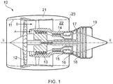
- a ducted fan gas turbine engine generally indicated at 10 has a principal and rotational axis X-X.
- the engine comprises, in axial flow series, an air intake 11, a propulsive fan 12, an intermediate pressure compressor 13, a high-pressure compressor 14, combustion equipment 15, a high-pressure turbine 16, and intermediate-pressure turbine 17, a low-pressure turbine 18 and a core engine exhaust nozzle 19.
- a nacelle 21 generally surrounds the engine 10 and defines the intake 11, a bypass duct 22 and a bypass exhaust nozzle 23.
- the gas turbine engine 10 works in a conventional manner so that air entering the intake 11 is accelerated by the fan 12 to produce two air flows: a first air flow A into the intermediate pressure compressor 14 and a second air flow B which passes through the bypass duct 22 to provide propulsive thrust.
- the intermediate pressure compressor 13 compresses the air flow A directed into it before delivering that air to the high pressure compressor 14 where further compression takes place.
- the compressed air exhausted from the high-pressure compressor 14 is directed into the combustion equipment 15 where it is mixed with fuel and the mixture combusted.
- the resultant hot combustion products then expand through, and thereby drive the high, intermediate and low-pressure turbines 16, 17, 18 before being exhausted through the nozzle 19 to provide additional propulsive thrust.
- the high, intermediate and low-pressure turbines respectively drive the high and intermediate pressure compressors 14, 13 and the fan 12 by suitable interconnecting shafts.
- the high-pressure turbine gas temperatures are hotter than the melting point of the material of the blades and vanes, necessitating internal air cooling of these airfoil components.
- the mean temperature of the gas stream decreases as power is extracted. Therefore, the need to cool the static and rotary parts of the engine structure decreases as the gas moves from the high-pressure stage(s), through the intermediate-pressure and low-pressure stages, and towards the exit nozzle.
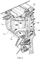
- Figure 2 shows an isometric view of a typical single stage cooled turbine. Cooling air flows are indicated by arrows.
- High-pressure turbine nozzle guide vanes 31 consume the greatest amount of cooling air on high temperature engines.
- High-pressure blades 32 typically use about half of the NGV flow.
- the intermediate-pressure and low-pressure stages downstream of the HP turbine use progressively less cooling air.
- the high-pressure turbine airfoils are cooled by using high pressure air from the compressor that has by-passed the combustor and is therefore relatively cool compared to the gas temperature.
- Typical cooling air temperatures are between 800 and 1000 Kelvin (K), while gas temperatures can be in excess of 2100 K.
- the cooling air from the compressor that is used to cool the hot turbine components is not used fully to extract work from the turbine. Therefore, as extracting coolant flow has an adverse effect on the engine operating efficiency, it is important to use the cooling air effectively.
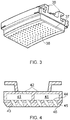
- Figure 3 shows an isometric view of a typical high-pressure turbine shroud segment.
- the segment which is mounted to an external casing by legs 36, provides an endwall 37 for the working gas annulus, an abradable coating being formed on the gas-washed surface of the endwall.
- a plurality of effusion exhaust holes 38 are formed in the endwall, cooling air passing from an internal plenum or plena through the holes to form a cooling film on the gas-washed surface.
- a turbine shroud includes a panel having a forward hook and an aft hook spaced therefrom.
- a primary cooling circuit extends through the panel adjacent the forward hook, and has a primary inlet for receiving primary air at a first pressure, and a primary outlet for discharging the primary air.
- a secondary cooling circuit extends through the panel adjacent the aft hook independently of the primary circuit. The secondary circuit includes a secondary inlet for receiving secondary air at a second pressure different than the first pressure, and a secondary outlet for discharging the secondary air.
- WO 94/17285 discloses a turbine vane for a gas turbine engine core adaptable to be operated in a variety of thrust regimes. Various construction details are developed which provide means to provide cooling of an inner platform of the turbine vane.
- US 2010/129196 discloses a gas turbine vane.
- a cooling circuit to the trailing edge of a vane airfoil is fed from the outer diameter platform, which prevents failure due to an oxidized and eroded airfoil trailing edge.
- the pressure of the cooling air in the plenum or plena must be kept above the hot gas annulus pressure to prevent ingestion.
- the plenum pressure must be kept above the peak of the pulse if ingestion of hot gas is to be avoided. However, between peaks, the excess plenum pressure can lead to excessive cooling air flow and hence can reduce engine operating efficiency.
- An aim of the present invention is to provide a turbine stage endwall component which can operate at lower plenum pressures while avoiding the detrimental effects of hot gas ingestion.
- the present invention provides a component of a turbine stage of a gas turbine engine, the component forming an endwall for the working gas annulus of the stage, and the component having:
- exhaust holes are formed as straight cylinders having a constant flow cross-sectional area from entrance to exit.
- the exhaust holes can have an increased fill volume, leading to expansion and pressure loss of any ingested hot gas.
- the time taken for the hot gas to penetrate the endwall after a pressure pulse can be increased, which in turn allows the pressure of cooling air in the plenum or plena to be reduced so that component can be operated at a lower average cooing air feed to exhaust pressure ratio.
- the component may have any one or, to the extent that they are compatible, any combination of the following optional features.
- the flow cross-sectional area may be greater at the intermediate position than it is at the exit by a factor of at least 1.5, and preferably by a factor of at least 2 or 4.
- the flow cross-sectional area is also greater at the intermediate position than it is at the entrance. In this way, any ingested hot gas can be better contained in the holes.
- the flow cross-sectional area may be greater at the intermediate position than it is at the entrance by a factor of at least 1.5, and preferably by a factor of at least 2 or 4.
- the component may be a shroud segment providing a close clearance to the tips of a row of turbine blades which sweep across the segment.
- Such segments experience pressure pulses as they are swept over by the blades, and thus can benefit from such exhaust holes.
- the component may be a turbine blade, an inner platform of the blade forming the endwall.
- the component may be a static guide vane, an inner and/or an outer platform of the vane forming the endwall.
- Each exhaust hole 43 expands in flow cross-sectional area from its entrance 44 to a maximum area at an intermediate position 46, and then contracts in flow cross-sectional area to its exit 45.
- the flow cross-sectional area at the intermediate position can be greater than the flow cross-sectional area at the entrance and/or the exit by a factor of at least 1.5, and preferably by a factor of at least 2 or 4.
- the cooling air in the plena is maintained at a pressure which prevents hot gas ingestion into the plena at the peak of each pressure pulse, but by adopting exhaust holes of the type shown in Figure 4 that pressure can be reduced, leading to consequent improvements in engine efficiency.
- Some hot gas ingestion into the exhaust holes occurs, but as long as the hot gas is prevented from mixing with the cooling gas in the plena, that hot gas is simply ejected from the holes after the peak of the pressure pulse is passed.
- FIG. 5 shows a schematic cross-sectional view through a high-pressure turbine shroud segment according to a second embodiment.
- each exhaust hole 43 expands in flow cross-sectional area from its entrance 44 to a maximum area at an intermediate position 46, and then contracting in flow cross-sectional area to its exit 45.
- the expansion and contraction is caused by the cavity of each exhaust hole being formed as a pair of base-to-base frustocones.
- the expansion and contraction is caused by the cavity being formed by two short cylindrical sections joined together by a large diameter sphere.
- Other shapes for the cavity can also be adopted, e.g. depending on manufacturing convenience.
- Figure 6 shows a schematic cross-sectional view through a high-pressure turbine shroud segment according to a third embodiment.
- the cavity of each exhaust hole 43 is formed by two end-to end cylinders, the interior cylinder having a greater diameter than the exterior cylinder. In this way, the hole contracts in flow cross-sectional area from its intermediate position 46 to its exit 45, but has a constant flow cross-sectional area from its entrance 44 to its intermediate position. Ingested hot gas experiences an expansion and pressure loss, and can thus still be detained in the holes.
Landscapes
- Engineering & Computer Science (AREA)
- Mechanical Engineering (AREA)
- General Engineering & Computer Science (AREA)
- Turbine Rotor Nozzle Sealing (AREA)
Claims (7)
- Komponente einer Turbinenstufe eines Gasturbinentriebwerks, wobei die Komponente eine Endwand für den Arbeitsgasring der Stufe bildet und die Komponente Folgendes aufweist:eine oder mehrere innere Luftkammern (41) hinter der Endwand (40), die bei Gebrauch einen Kühlluftstrom enthalten, undeine Vielzahl von Auslasslöchern (43) in der Endwand, wobei sich jedes Auslassloch so zwischen den Luftkammern und einer gasgewaschenen Fläche der Endwand erstreckt, dass die Kühlluft durch die Löcher ausströmt, um einen Kühlfilm über der gasgewaschenen Fläche zu bilden;wobei jedes Auslassloch eine Strömungsquerschnittsfläche aufweist, die an einer Zwischenstelle (46) zwischen dem Eingang (44) des Lochs von der jeweiligen Luftkammer und dem Ausgang (45) des Lochs zur gasgewaschenen Fläche größer ist als am Ausgang.
- Komponente nach Anspruch 1, wobei die Strömungsquerschnittsfläche an der Zwischenstelle um einen Faktor von mindestens 1,5 größer ist als am Ausgang.
- Komponente nach Anspruch 1 oder 2, wobei die Strömungsquerschnittsfläche an der Zwischenstelle größer ist als am Eingang.
- Komponente nach Anspruch 3, wobei die Strömungsquerschnittsfläche an der Zwischenstelle um einen Faktor von mindestens 1,5 größer ist als am Eingang.
- Komponente nach einem der vorhergehenden Ansprüche, bei der es sich um ein Mantelsegment handelt, das einen engen Abstand zu den Spitzen einer Reihe von Turbinenschaufeln bereitstellt, die über das Segment streifen.
- Komponente nach einem der Ansprüche 1 bis 4, bei der es sich um eine Turbinenschaufel handelt, wobei eine innere Plattform der Schaufel die Endwand bildet.
- Komponente nach einem der Ansprüche 1 bis 4, bei der es sich um eine statische Leitschaufel handelt, wobei eine innere und/oder eine äußere Plattform der Schaufel die Endwand bildet.
Applications Claiming Priority (1)
| Application Number | Priority Date | Filing Date | Title |
|---|---|---|---|
| GB201103176A GB201103176D0 (en) | 2011-02-24 | 2011-02-24 | Endwall component for a turbine stage of a gas turbine engine |
Publications (3)
| Publication Number | Publication Date |
|---|---|
| EP2492454A2 EP2492454A2 (de) | 2012-08-29 |
| EP2492454A3 EP2492454A3 (de) | 2017-11-01 |
| EP2492454B1 true EP2492454B1 (de) | 2018-09-12 |
Family
ID=43881596
Family Applications (1)
| Application Number | Title | Priority Date | Filing Date |
|---|---|---|---|
| EP12154473.8A Not-in-force EP2492454B1 (de) | 2011-02-24 | 2012-02-08 | Endwandkomponente für eine Turbinenstufe eines Triebwerks |
Country Status (3)
| Country | Link |
|---|---|
| US (1) | US9068472B2 (de) |
| EP (1) | EP2492454B1 (de) |
| GB (1) | GB201103176D0 (de) |
Families Citing this family (15)
| Publication number | Priority date | Publication date | Assignee | Title |
|---|---|---|---|---|
| EP3071796B1 (de) | 2013-11-18 | 2021-12-01 | Raytheon Technologies Corporation | Verstellbare leitschaufel mit endwandkonturierung für einen gasturbinenmotor |
| WO2015076961A1 (en) | 2013-11-22 | 2015-05-28 | United Technologies Corporation | Endwall countouring trench |
| EP2990605A1 (de) * | 2014-08-26 | 2016-03-02 | Siemens Aktiengesellschaft | Turbinenschaufel |
| US10641120B2 (en) * | 2015-07-24 | 2020-05-05 | Rolls-Royce Corporation | Seal segment for a gas turbine engine |
| US9869202B2 (en) * | 2015-08-14 | 2018-01-16 | United Technologies Corporation | Blade outer air seal for a gas turbine engine |
| US10815827B2 (en) * | 2016-01-25 | 2020-10-27 | Raytheon Technologies Corporation | Variable thickness core for gas turbine engine component |
| US10280763B2 (en) * | 2016-06-08 | 2019-05-07 | Ansaldo Energia Switzerland AG | Airfoil cooling passageways for generating improved protective film |
| GB201700914D0 (en) * | 2017-01-19 | 2017-03-08 | Rolls Royce Plc | A sealing element and a method of maufacturing the same |
| US10677084B2 (en) | 2017-06-16 | 2020-06-09 | Honeywell International Inc. | Turbine tip shroud assembly with plural shroud segments having inter-segment seal arrangement |
| US10900378B2 (en) | 2017-06-16 | 2021-01-26 | Honeywell International Inc. | Turbine tip shroud assembly with plural shroud segments having internal cooling passages |
| EP3480431A1 (de) * | 2017-11-02 | 2019-05-08 | MTU Aero Engines GmbH | Bauteil für eine gasturbine mit einer struktur mit einem gradienten im elastizitätsmodul und additives herstellungsverfahren |
| US10502093B2 (en) * | 2017-12-13 | 2019-12-10 | Pratt & Whitney Canada Corp. | Turbine shroud cooling |
| US10989068B2 (en) | 2018-07-19 | 2021-04-27 | General Electric Company | Turbine shroud including plurality of cooling passages |
| US10837315B2 (en) * | 2018-10-25 | 2020-11-17 | General Electric Company | Turbine shroud including cooling passages in communication with collection plenums |
| US11047250B2 (en) * | 2019-04-05 | 2021-06-29 | Raytheon Technologies Corporation | CMC BOAS transverse hook arrangement |
Family Cites Families (18)
| Publication number | Priority date | Publication date | Assignee | Title |
|---|---|---|---|---|
| US3365172A (en) * | 1966-11-02 | 1968-01-23 | Gen Electric | Air cooled shroud seal |
| US3542486A (en) * | 1968-09-27 | 1970-11-24 | Gen Electric | Film cooling of structural members in gas turbine engines |
| US4526226A (en) * | 1981-08-31 | 1985-07-02 | General Electric Company | Multiple-impingement cooled structure |
| US4770608A (en) * | 1985-12-23 | 1988-09-13 | United Technologies Corporation | Film cooled vanes and turbines |
| US4669957A (en) | 1985-12-23 | 1987-06-02 | United Technologies Corporation | Film coolant passage with swirl diffuser |
| GB2202907A (en) | 1987-03-26 | 1988-10-05 | Secr Defence | Cooled aerofoil components |
| US5382135A (en) * | 1992-11-24 | 1995-01-17 | United Technologies Corporation | Rotor blade with cooled integral platform |
| US5344283A (en) * | 1993-01-21 | 1994-09-06 | United Technologies Corporation | Turbine vane having dedicated inner platform cooling |
| US5993150A (en) * | 1998-01-16 | 1999-11-30 | General Electric Company | Dual cooled shroud |
| US6155778A (en) * | 1998-12-30 | 2000-12-05 | General Electric Company | Recessed turbine shroud |
| US6254347B1 (en) * | 1999-11-03 | 2001-07-03 | General Electric Company | Striated cooling hole |
| US7097417B2 (en) * | 2004-02-09 | 2006-08-29 | Siemens Westinghouse Power Corporation | Cooling system for an airfoil vane |
| US7866948B1 (en) | 2006-08-16 | 2011-01-11 | Florida Turbine Technologies, Inc. | Turbine airfoil with near-wall impingement and vortex cooling |
| US7722327B1 (en) * | 2007-04-03 | 2010-05-25 | Florida Turbine Technologies, Inc. | Multiple vortex cooling circuit for a thin airfoil |
| US7775769B1 (en) | 2007-05-24 | 2010-08-17 | Florida Turbine Technologies, Inc. | Turbine airfoil fillet region cooling |
| GB0810986D0 (en) | 2008-06-17 | 2008-07-23 | Rolls Royce Plc | A Cooling arrangement |
| US20100008759A1 (en) | 2008-07-10 | 2010-01-14 | General Electric Company | Methods and apparatuses for providing film cooling to turbine components |
| US8142137B2 (en) * | 2008-11-26 | 2012-03-27 | Alstom Technology Ltd | Cooled gas turbine vane assembly |
-
2011
- 2011-02-24 GB GB201103176A patent/GB201103176D0/en not_active Ceased
-
2012
- 2012-02-08 EP EP12154473.8A patent/EP2492454B1/de not_active Not-in-force
- 2012-02-08 US US13/368,718 patent/US9068472B2/en active Active
Non-Patent Citations (1)
| Title |
|---|
| None * |
Also Published As
| Publication number | Publication date |
|---|---|
| US9068472B2 (en) | 2015-06-30 |
| GB201103176D0 (en) | 2011-04-06 |
| EP2492454A2 (de) | 2012-08-29 |
| US20120219401A1 (en) | 2012-08-30 |
| EP2492454A3 (de) | 2017-11-01 |
Similar Documents
| Publication | Publication Date | Title |
|---|---|---|
| EP2492454B1 (de) | Endwandkomponente für eine Turbinenstufe eines Triebwerks | |
| US9115590B2 (en) | Gas turbine engine airfoil cooling circuit | |
| US20190316475A1 (en) | Platform cooling core for a gas turbine engine rotor blade | |
| EP2746536A1 (de) | Rotorstufe einer Turbine | |
| US9382811B2 (en) | Aerofoil cooling arrangement | |
| US10215051B2 (en) | Gas turbine engine component providing prioritized cooling | |
| EP2505787A1 (de) | Bauteil eines Gasturbinenkraftwerks und zugehöriges Gasturbinenkraftwerk | |
| WO2009087346A1 (en) | Blade cooling | |
| US8297925B2 (en) | Aerofoil configuration | |
| EP3084136A2 (de) | Rotorschaufelplattformkühlkanal | |
| US10344620B2 (en) | Air cooled component for a gas turbine engine | |
| EP3090126A1 (de) | Endwandkonturgraben | |
| EP3063388A1 (de) | Sockel mit wärmetransferverstärker | |
| US20120076645A1 (en) | Endwall component for a turbine stage of a gas turbine engine | |
| EP3054093B1 (de) | Anordnung von turbulatoren | |
| EP3170976A1 (de) | Gasturbinenmotorkomponente mit einem plattformkernkühlkreis, zugehöriges kühlsystem und gasturbinenmotor | |
| US9376918B2 (en) | Aerofoil cooling arrangement | |
| CN108779679B (zh) | 被冷却的涡轮叶片 | |
| EP2604795B1 (de) | Laufschaufel oder -leitschaufel | |
| US9790801B2 (en) | Gas turbine engine component having suction side cutback opening | |
| EP3453833B1 (de) | Turbinenschaufel und zugehöriges gasturbinentriebwerk |
Legal Events
| Date | Code | Title | Description |
|---|---|---|---|
| PUAI | Public reference made under article 153(3) epc to a published international application that has entered the european phase |
Free format text: ORIGINAL CODE: 0009012 |
|
| AK | Designated contracting states |
Kind code of ref document: A2 Designated state(s): AL AT BE BG CH CY CZ DE DK EE ES FI FR GB GR HR HU IE IS IT LI LT LU LV MC MK MT NL NO PL PT RO RS SE SI SK SM TR |
|
| AX | Request for extension of the european patent |
Extension state: BA ME |
|
| RAP1 | Party data changed (applicant data changed or rights of an application transferred) |
Owner name: ROLLS-ROYCE PLC |
|
| PUAL | Search report despatched |
Free format text: ORIGINAL CODE: 0009013 |
|
| AK | Designated contracting states |
Kind code of ref document: A3 Designated state(s): AL AT BE BG CH CY CZ DE DK EE ES FI FR GB GR HR HU IE IS IT LI LT LU LV MC MK MT NL NO PL PT RO RS SE SI SK SM TR |
|
| AX | Request for extension of the european patent |
Extension state: BA ME |
|
| RIC1 | Information provided on ipc code assigned before grant |
Ipc: F01D 11/12 20060101ALI20170925BHEP Ipc: F01D 5/18 20060101ALI20170925BHEP Ipc: F01D 25/12 20060101AFI20170925BHEP |
|
| STAA | Information on the status of an ep patent application or granted ep patent |
Free format text: STATUS: REQUEST FOR EXAMINATION WAS MADE |
|
| 17P | Request for examination filed |
Effective date: 20180501 |
|
| RBV | Designated contracting states (corrected) |
Designated state(s): AL AT BE BG CH CY CZ DE DK EE ES FI FR GB GR HR HU IE IS IT LI LT LU LV MC MK MT NL NO PL PT RO RS SE SI SK SM TR |
|
| RIC1 | Information provided on ipc code assigned before grant |
Ipc: F01D 25/12 20060101AFI20180607BHEP Ipc: F01D 5/18 20060101ALI20180607BHEP Ipc: F01D 11/12 20060101ALI20180607BHEP |
|
| GRAP | Despatch of communication of intention to grant a patent |
Free format text: ORIGINAL CODE: EPIDOSNIGR1 |
|
| STAA | Information on the status of an ep patent application or granted ep patent |
Free format text: STATUS: GRANT OF PATENT IS INTENDED |
|
| GRAS | Grant fee paid |
Free format text: ORIGINAL CODE: EPIDOSNIGR3 |
|
| GRAA | (expected) grant |
Free format text: ORIGINAL CODE: 0009210 |
|
| STAA | Information on the status of an ep patent application or granted ep patent |
Free format text: STATUS: THE PATENT HAS BEEN GRANTED |
|
| INTG | Intention to grant announced |
Effective date: 20180717 |
|
| AK | Designated contracting states |
Kind code of ref document: B1 Designated state(s): AL AT BE BG CH CY CZ DE DK EE ES FI FR GB GR HR HU IE IS IT LI LT LU LV MC MK MT NL NO PL PT RO RS SE SI SK SM TR |
|
| REG | Reference to a national code |
Ref country code: GB Ref legal event code: FG4D |
|
| REG | Reference to a national code |
Ref country code: CH Ref legal event code: EP |
|
| REG | Reference to a national code |
Ref country code: IE Ref legal event code: FG4D |
|
| REG | Reference to a national code |
Ref country code: DE Ref legal event code: R096 Ref document number: 602012050881 Country of ref document: DE |
|
| REG | Reference to a national code |
Ref country code: AT Ref legal event code: REF Ref document number: 1040834 Country of ref document: AT Kind code of ref document: T Effective date: 20181015 |
|
| REG | Reference to a national code |
Ref country code: NL Ref legal event code: MP Effective date: 20180912 |
|
| REG | Reference to a national code |
Ref country code: LT Ref legal event code: MG4D |
|
| PG25 | Lapsed in a contracting state [announced via postgrant information from national office to epo] |
Ref country code: NO Free format text: LAPSE BECAUSE OF FAILURE TO SUBMIT A TRANSLATION OF THE DESCRIPTION OR TO PAY THE FEE WITHIN THE PRESCRIBED TIME-LIMIT Effective date: 20181212 Ref country code: BG Free format text: LAPSE BECAUSE OF FAILURE TO SUBMIT A TRANSLATION OF THE DESCRIPTION OR TO PAY THE FEE WITHIN THE PRESCRIBED TIME-LIMIT Effective date: 20181212 Ref country code: SE Free format text: LAPSE BECAUSE OF FAILURE TO SUBMIT A TRANSLATION OF THE DESCRIPTION OR TO PAY THE FEE WITHIN THE PRESCRIBED TIME-LIMIT Effective date: 20180912 Ref country code: LT Free format text: LAPSE BECAUSE OF FAILURE TO SUBMIT A TRANSLATION OF THE DESCRIPTION OR TO PAY THE FEE WITHIN THE PRESCRIBED TIME-LIMIT Effective date: 20180912 Ref country code: FI Free format text: LAPSE BECAUSE OF FAILURE TO SUBMIT A TRANSLATION OF THE DESCRIPTION OR TO PAY THE FEE WITHIN THE PRESCRIBED TIME-LIMIT Effective date: 20180912 Ref country code: RS Free format text: LAPSE BECAUSE OF FAILURE TO SUBMIT A TRANSLATION OF THE DESCRIPTION OR TO PAY THE FEE WITHIN THE PRESCRIBED TIME-LIMIT Effective date: 20180912 Ref country code: GR Free format text: LAPSE BECAUSE OF FAILURE TO SUBMIT A TRANSLATION OF THE DESCRIPTION OR TO PAY THE FEE WITHIN THE PRESCRIBED TIME-LIMIT Effective date: 20181213 |
|
| PG25 | Lapsed in a contracting state [announced via postgrant information from national office to epo] |
Ref country code: HR Free format text: LAPSE BECAUSE OF FAILURE TO SUBMIT A TRANSLATION OF THE DESCRIPTION OR TO PAY THE FEE WITHIN THE PRESCRIBED TIME-LIMIT Effective date: 20180912 Ref country code: AL Free format text: LAPSE BECAUSE OF FAILURE TO SUBMIT A TRANSLATION OF THE DESCRIPTION OR TO PAY THE FEE WITHIN THE PRESCRIBED TIME-LIMIT Effective date: 20180912 Ref country code: LV Free format text: LAPSE BECAUSE OF FAILURE TO SUBMIT A TRANSLATION OF THE DESCRIPTION OR TO PAY THE FEE WITHIN THE PRESCRIBED TIME-LIMIT Effective date: 20180912 |
|
| REG | Reference to a national code |
Ref country code: AT Ref legal event code: MK05 Ref document number: 1040834 Country of ref document: AT Kind code of ref document: T Effective date: 20180912 |
|
| PG25 | Lapsed in a contracting state [announced via postgrant information from national office to epo] |
Ref country code: RO Free format text: LAPSE BECAUSE OF FAILURE TO SUBMIT A TRANSLATION OF THE DESCRIPTION OR TO PAY THE FEE WITHIN THE PRESCRIBED TIME-LIMIT Effective date: 20180912 Ref country code: AT Free format text: LAPSE BECAUSE OF FAILURE TO SUBMIT A TRANSLATION OF THE DESCRIPTION OR TO PAY THE FEE WITHIN THE PRESCRIBED TIME-LIMIT Effective date: 20180912 Ref country code: EE Free format text: LAPSE BECAUSE OF FAILURE TO SUBMIT A TRANSLATION OF THE DESCRIPTION OR TO PAY THE FEE WITHIN THE PRESCRIBED TIME-LIMIT Effective date: 20180912 Ref country code: IT Free format text: LAPSE BECAUSE OF FAILURE TO SUBMIT A TRANSLATION OF THE DESCRIPTION OR TO PAY THE FEE WITHIN THE PRESCRIBED TIME-LIMIT Effective date: 20180912 Ref country code: ES Free format text: LAPSE BECAUSE OF FAILURE TO SUBMIT A TRANSLATION OF THE DESCRIPTION OR TO PAY THE FEE WITHIN THE PRESCRIBED TIME-LIMIT Effective date: 20180912 Ref country code: CZ Free format text: LAPSE BECAUSE OF FAILURE TO SUBMIT A TRANSLATION OF THE DESCRIPTION OR TO PAY THE FEE WITHIN THE PRESCRIBED TIME-LIMIT Effective date: 20180912 Ref country code: NL Free format text: LAPSE BECAUSE OF FAILURE TO SUBMIT A TRANSLATION OF THE DESCRIPTION OR TO PAY THE FEE WITHIN THE PRESCRIBED TIME-LIMIT Effective date: 20180912 Ref country code: IS Free format text: LAPSE BECAUSE OF FAILURE TO SUBMIT A TRANSLATION OF THE DESCRIPTION OR TO PAY THE FEE WITHIN THE PRESCRIBED TIME-LIMIT Effective date: 20190112 Ref country code: PL Free format text: LAPSE BECAUSE OF FAILURE TO SUBMIT A TRANSLATION OF THE DESCRIPTION OR TO PAY THE FEE WITHIN THE PRESCRIBED TIME-LIMIT Effective date: 20180912 |
|
| PG25 | Lapsed in a contracting state [announced via postgrant information from national office to epo] |
Ref country code: SK Free format text: LAPSE BECAUSE OF FAILURE TO SUBMIT A TRANSLATION OF THE DESCRIPTION OR TO PAY THE FEE WITHIN THE PRESCRIBED TIME-LIMIT Effective date: 20180912 Ref country code: PT Free format text: LAPSE BECAUSE OF FAILURE TO SUBMIT A TRANSLATION OF THE DESCRIPTION OR TO PAY THE FEE WITHIN THE PRESCRIBED TIME-LIMIT Effective date: 20190112 Ref country code: SM Free format text: LAPSE BECAUSE OF FAILURE TO SUBMIT A TRANSLATION OF THE DESCRIPTION OR TO PAY THE FEE WITHIN THE PRESCRIBED TIME-LIMIT Effective date: 20180912 |
|
| REG | Reference to a national code |
Ref country code: DE Ref legal event code: R097 Ref document number: 602012050881 Country of ref document: DE |
|
| PLBE | No opposition filed within time limit |
Free format text: ORIGINAL CODE: 0009261 |
|
| STAA | Information on the status of an ep patent application or granted ep patent |
Free format text: STATUS: NO OPPOSITION FILED WITHIN TIME LIMIT |
|
| PG25 | Lapsed in a contracting state [announced via postgrant information from national office to epo] |
Ref country code: DK Free format text: LAPSE BECAUSE OF FAILURE TO SUBMIT A TRANSLATION OF THE DESCRIPTION OR TO PAY THE FEE WITHIN THE PRESCRIBED TIME-LIMIT Effective date: 20180912 |
|
| 26N | No opposition filed |
Effective date: 20190613 |
|
| PG25 | Lapsed in a contracting state [announced via postgrant information from national office to epo] |
Ref country code: SI Free format text: LAPSE BECAUSE OF FAILURE TO SUBMIT A TRANSLATION OF THE DESCRIPTION OR TO PAY THE FEE WITHIN THE PRESCRIBED TIME-LIMIT Effective date: 20180912 |
|
| REG | Reference to a national code |
Ref country code: CH Ref legal event code: PL |
|
| PG25 | Lapsed in a contracting state [announced via postgrant information from national office to epo] |
Ref country code: MC Free format text: LAPSE BECAUSE OF FAILURE TO SUBMIT A TRANSLATION OF THE DESCRIPTION OR TO PAY THE FEE WITHIN THE PRESCRIBED TIME-LIMIT Effective date: 20180912 Ref country code: LU Free format text: LAPSE BECAUSE OF NON-PAYMENT OF DUE FEES Effective date: 20190208 |
|
| REG | Reference to a national code |
Ref country code: BE Ref legal event code: MM Effective date: 20190228 |
|
| REG | Reference to a national code |
Ref country code: IE Ref legal event code: MM4A |
|
| PG25 | Lapsed in a contracting state [announced via postgrant information from national office to epo] |
Ref country code: LI Free format text: LAPSE BECAUSE OF NON-PAYMENT OF DUE FEES Effective date: 20190228 Ref country code: CH Free format text: LAPSE BECAUSE OF NON-PAYMENT OF DUE FEES Effective date: 20190228 |
|
| PG25 | Lapsed in a contracting state [announced via postgrant information from national office to epo] |
Ref country code: IE Free format text: LAPSE BECAUSE OF NON-PAYMENT OF DUE FEES Effective date: 20190208 |
|
| PG25 | Lapsed in a contracting state [announced via postgrant information from national office to epo] |
Ref country code: BE Free format text: LAPSE BECAUSE OF NON-PAYMENT OF DUE FEES Effective date: 20190228 |
|
| PG25 | Lapsed in a contracting state [announced via postgrant information from national office to epo] |
Ref country code: TR Free format text: LAPSE BECAUSE OF FAILURE TO SUBMIT A TRANSLATION OF THE DESCRIPTION OR TO PAY THE FEE WITHIN THE PRESCRIBED TIME-LIMIT Effective date: 20180912 |
|
| PG25 | Lapsed in a contracting state [announced via postgrant information from national office to epo] |
Ref country code: MT Free format text: LAPSE BECAUSE OF NON-PAYMENT OF DUE FEES Effective date: 20190208 |
|
| PG25 | Lapsed in a contracting state [announced via postgrant information from national office to epo] |
Ref country code: CY Free format text: LAPSE BECAUSE OF FAILURE TO SUBMIT A TRANSLATION OF THE DESCRIPTION OR TO PAY THE FEE WITHIN THE PRESCRIBED TIME-LIMIT Effective date: 20180912 |
|
| PG25 | Lapsed in a contracting state [announced via postgrant information from national office to epo] |
Ref country code: HU Free format text: LAPSE BECAUSE OF FAILURE TO SUBMIT A TRANSLATION OF THE DESCRIPTION OR TO PAY THE FEE WITHIN THE PRESCRIBED TIME-LIMIT; INVALID AB INITIO Effective date: 20120208 |
|
| PGFP | Annual fee paid to national office [announced via postgrant information from national office to epo] |
Ref country code: GB Payment date: 20220222 Year of fee payment: 11 Ref country code: DE Payment date: 20220225 Year of fee payment: 11 |
|
| PGFP | Annual fee paid to national office [announced via postgrant information from national office to epo] |
Ref country code: FR Payment date: 20220224 Year of fee payment: 11 |
|
| PG25 | Lapsed in a contracting state [announced via postgrant information from national office to epo] |
Ref country code: MK Free format text: LAPSE BECAUSE OF FAILURE TO SUBMIT A TRANSLATION OF THE DESCRIPTION OR TO PAY THE FEE WITHIN THE PRESCRIBED TIME-LIMIT Effective date: 20180912 |
|
| P01 | Opt-out of the competence of the unified patent court (upc) registered |
Effective date: 20230528 |
|
| REG | Reference to a national code |
Ref country code: DE Ref legal event code: R119 Ref document number: 602012050881 Country of ref document: DE |
|
| GBPC | Gb: european patent ceased through non-payment of renewal fee |
Effective date: 20230208 |
|
| PG25 | Lapsed in a contracting state [announced via postgrant information from national office to epo] |
Ref country code: GB Free format text: LAPSE BECAUSE OF NON-PAYMENT OF DUE FEES Effective date: 20230208 |
|
| PG25 | Lapsed in a contracting state [announced via postgrant information from national office to epo] |
Ref country code: GB Free format text: LAPSE BECAUSE OF NON-PAYMENT OF DUE FEES Effective date: 20230208 Ref country code: FR Free format text: LAPSE BECAUSE OF NON-PAYMENT OF DUE FEES Effective date: 20230228 Ref country code: DE Free format text: LAPSE BECAUSE OF NON-PAYMENT OF DUE FEES Effective date: 20230901 |