EP2492441A2 - System for measuring parameters of fluid flow in turbomachinery - Google Patents
System for measuring parameters of fluid flow in turbomachinery Download PDFInfo
- Publication number
- EP2492441A2 EP2492441A2 EP12156954A EP12156954A EP2492441A2 EP 2492441 A2 EP2492441 A2 EP 2492441A2 EP 12156954 A EP12156954 A EP 12156954A EP 12156954 A EP12156954 A EP 12156954A EP 2492441 A2 EP2492441 A2 EP 2492441A2
- Authority
- EP
- European Patent Office
- Prior art keywords
- rake
- probe
- boundary layer
- flow
- coolant
- Prior art date
- Legal status (The legal status is an assumption and is not a legal conclusion. Google has not performed a legal analysis and makes no representation as to the accuracy of the status listed.)
- Withdrawn
Links
- 239000012530 fluid Substances 0.000 title description 37
- 239000002826 coolant Substances 0.000 claims abstract description 66
- 239000000523 sample Substances 0.000 claims abstract description 31
- 238000001816 cooling Methods 0.000 claims description 86
- 239000007788 liquid Substances 0.000 claims description 8
- 239000007789 gas Substances 0.000 description 33
- 238000005259 measurement Methods 0.000 description 24
- 239000000567 combustion gas Substances 0.000 description 22
- 238000013461 design Methods 0.000 description 9
- 238000004458 analytical method Methods 0.000 description 7
- 239000000463 material Substances 0.000 description 7
- 238000002485 combustion reaction Methods 0.000 description 6
- MWUXSHHQAYIFBG-UHFFFAOYSA-N nitrogen oxide Inorganic materials O=[N] MWUXSHHQAYIFBG-UHFFFAOYSA-N 0.000 description 6
- 238000002844 melting Methods 0.000 description 5
- 230000008018 melting Effects 0.000 description 5
- 239000012720 thermal barrier coating Substances 0.000 description 5
- 239000000112 cooling gas Substances 0.000 description 4
- 230000007423 decrease Effects 0.000 description 4
- 239000000203 mixture Substances 0.000 description 4
- 238000012360 testing method Methods 0.000 description 4
- 239000003344 environmental pollutant Substances 0.000 description 3
- 231100000719 pollutant Toxicity 0.000 description 3
- 239000000047 product Substances 0.000 description 3
- XLYOFNOQVPJJNP-UHFFFAOYSA-N water Substances O XLYOFNOQVPJJNP-UHFFFAOYSA-N 0.000 description 3
- UGFAIRIUMAVXCW-UHFFFAOYSA-N Carbon monoxide Chemical class [O+]#[C-] UGFAIRIUMAVXCW-UHFFFAOYSA-N 0.000 description 2
- 229910002090 carbon oxide Inorganic materials 0.000 description 2
- 238000004891 communication Methods 0.000 description 2
- 238000011161 development Methods 0.000 description 2
- 238000010586 diagram Methods 0.000 description 2
- 230000001788 irregular Effects 0.000 description 2
- 238000004519 manufacturing process Methods 0.000 description 2
- 239000013618 particulate matter Substances 0.000 description 2
- XTQHKBHJIVJGKJ-UHFFFAOYSA-N sulfur monoxide Chemical class S=O XTQHKBHJIVJGKJ-UHFFFAOYSA-N 0.000 description 2
- 229910052815 sulfur oxide Inorganic materials 0.000 description 2
- 230000003685 thermal hair damage Effects 0.000 description 2
- 238000011144 upstream manufacturing Methods 0.000 description 2
- 238000009529 body temperature measurement Methods 0.000 description 1
- 239000012809 cooling fluid Substances 0.000 description 1
- 230000006378 damage Effects 0.000 description 1
- 238000007405 data analysis Methods 0.000 description 1
- 238000013480 data collection Methods 0.000 description 1
- 230000000694 effects Effects 0.000 description 1
- 239000000446 fuel Substances 0.000 description 1
- 230000003137 locomotive effect Effects 0.000 description 1
- 238000000034 method Methods 0.000 description 1
- 230000037361 pathway Effects 0.000 description 1
- 238000010248 power generation Methods 0.000 description 1
- 239000000779 smoke Substances 0.000 description 1
- 239000013589 supplement Substances 0.000 description 1
Images
Classifications
-
- F—MECHANICAL ENGINEERING; LIGHTING; HEATING; WEAPONS; BLASTING
- F01—MACHINES OR ENGINES IN GENERAL; ENGINE PLANTS IN GENERAL; STEAM ENGINES
- F01D—NON-POSITIVE DISPLACEMENT MACHINES OR ENGINES, e.g. STEAM TURBINES
- F01D17/00—Regulating or controlling by varying flow
- F01D17/02—Arrangement of sensing elements
- F01D17/08—Arrangement of sensing elements responsive to condition of working-fluid, e.g. pressure
-
- G—PHYSICS
- G01—MEASURING; TESTING
- G01K—MEASURING TEMPERATURE; MEASURING QUANTITY OF HEAT; THERMALLY-SENSITIVE ELEMENTS NOT OTHERWISE PROVIDED FOR
- G01K13/00—Thermometers specially adapted for specific purposes
- G01K13/02—Thermometers specially adapted for specific purposes for measuring temperature of moving fluids or granular materials capable of flow
-
- G—PHYSICS
- G01—MEASURING; TESTING
- G01L—MEASURING FORCE, STRESS, TORQUE, WORK, MECHANICAL POWER, MECHANICAL EFFICIENCY, OR FLUID PRESSURE
- G01L19/00—Details of, or accessories for, apparatus for measuring steady or quasi-steady pressure of a fluent medium insofar as such details or accessories are not special to particular types of pressure gauges
- G01L19/06—Means for preventing overload or deleterious influence of the measured medium on the measuring device or vice versa
- G01L19/0681—Protection against excessive heat
-
- F—MECHANICAL ENGINEERING; LIGHTING; HEATING; WEAPONS; BLASTING
- F05—INDEXING SCHEMES RELATING TO ENGINES OR PUMPS IN VARIOUS SUBCLASSES OF CLASSES F01-F04
- F05D—INDEXING SCHEME FOR ASPECTS RELATING TO NON-POSITIVE-DISPLACEMENT MACHINES OR ENGINES, GAS-TURBINES OR JET-PROPULSION PLANTS
- F05D2260/00—Function
- F05D2260/20—Heat transfer, e.g. cooling
- F05D2260/201—Heat transfer, e.g. cooling by impingement of a fluid
-
- F—MECHANICAL ENGINEERING; LIGHTING; HEATING; WEAPONS; BLASTING
- F05—INDEXING SCHEMES RELATING TO ENGINES OR PUMPS IN VARIOUS SUBCLASSES OF CLASSES F01-F04
- F05D—INDEXING SCHEME FOR ASPECTS RELATING TO NON-POSITIVE-DISPLACEMENT MACHINES OR ENGINES, GAS-TURBINES OR JET-PROPULSION PLANTS
- F05D2260/00—Function
- F05D2260/20—Heat transfer, e.g. cooling
- F05D2260/202—Heat transfer, e.g. cooling by film cooling
-
- G—PHYSICS
- G01—MEASURING; TESTING
- G01K—MEASURING TEMPERATURE; MEASURING QUANTITY OF HEAT; THERMALLY-SENSITIVE ELEMENTS NOT OTHERWISE PROVIDED FOR
- G01K13/00—Thermometers specially adapted for specific purposes
- G01K13/02—Thermometers specially adapted for specific purposes for measuring temperature of moving fluids or granular materials capable of flow
- G01K13/024—Thermometers specially adapted for specific purposes for measuring temperature of moving fluids or granular materials capable of flow of moving gases
-
- Y—GENERAL TAGGING OF NEW TECHNOLOGICAL DEVELOPMENTS; GENERAL TAGGING OF CROSS-SECTIONAL TECHNOLOGIES SPANNING OVER SEVERAL SECTIONS OF THE IPC; TECHNICAL SUBJECTS COVERED BY FORMER USPC CROSS-REFERENCE ART COLLECTIONS [XRACs] AND DIGESTS
- Y02—TECHNOLOGIES OR APPLICATIONS FOR MITIGATION OR ADAPTATION AGAINST CLIMATE CHANGE
- Y02T—CLIMATE CHANGE MITIGATION TECHNOLOGIES RELATED TO TRANSPORTATION
- Y02T50/00—Aeronautics or air transport
- Y02T50/60—Efficient propulsion technologies, e.g. for aircraft
Definitions
- the disclosed subject matter relates to turbomachinery, such as a gas turbine engine. More particularly, the disclosed subject matter relates to systems for measuring parameters of a fluid flow in various turbomachinery.
- turbomachinery such as a gas turbine engine
- the design and operation of turbomachinery may benefit from improved measurements of various parameters of a fluid flow. These measurements may relate to the temperature, pressure, flow rate, or emissions levels in the fluid flow.
- existing systems do not provide boundary layer measurements within a boundary layer along a wall of the fluid flow. As a result, existing systems may not enable a complete or accurate analysis of the fluid flow, thereby resulting in less than optimal decisions for the design and operation of the turbomachinery.
- the invention resides in a system including a flow path rake, including a rake body, a coolant path extending through the rake body, and a first probe coupled to the rake body, wherein the first probe is configured to measure a first parameter of a flow along a flow path.
- the flow path rake may be a boundary layer rake, and wherein the first probe is configured to measure a first parameter of a first boundary layer flow along a first wall.
- the coolant path may comprise a gas coolant path comprising a plurality of film cooling outlets in the rake body.
- the disclosed embodiments enable near wall measurements within a boundary layer along a wall of a fluid flow using a boundary layer rake.
- the boundary layer measurements supplement primary measurements by a primary rake extending across the fluid flow, thereby enabling a more complete analysis and model of the fluid flow. These measurements may relate to the temperature, pressure, flow rate, pollutant emissions levels, smoke levels, flame presence, gas composition, or any other parameter of the fluid flow.
- the boundary layer rake and the primary rake may be used to acquire measurements in a combustor or a turbine of a gas turbine engine.
- the improved analysis and model of the fluid flow may enable improved decisions for the design and operation of various turbomachinery, such as the gas turbine engine.
- the disclosed embodiments of the rake may be used in various test rigs with a high temperature flow path, combustion test stands that simulate a single combustor section of a gas turbine, or any other flow path benefiting from boundary layer measurements.
- the disclosed embodiments may provide a coolant path through the boundary layer rake and the primary rake.
- the coolant path may be configured to circulate a coolant fluid (e.g., a liquid or gas coolant) through the boundary layer rake and the primary rake, thereby protecting the rake from damage due to heat in the fluid flow, e.g., hot combustion products.
- a coolant fluid e.g., a liquid or gas coolant
- the coolant path may lead to outlet ports or vents (e.g., film cooling orifices) in the boundary layer rake and the primary rake, thereby allowing at least some of the coolant to exit from the rake into the fluid flow.
- the discharged coolant may flow at partially along an external surface of the boundary layer rake and the primary rake to provide thermal shielding and cooling of the external surface (e.g., film cooling). Accordingly, the disclosed embodiments improve the acquisition of data in various fluid flows, such as flows of hot combustion products.
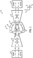
- FIG. 1 is a schematic flow diagram of an embodiment of a system 10 with a gas turbine 12 that may employ a near wall rake or boundary layer rake.
- the rear wall rake may be disposed along a wall within a boundary layer of a fluid flow to improve measurements of the fluid flow.
- the system 10 may include an aircraft, a watercraft, a locomotive, a power generation system, or combinations thereof.
- the illustrated gas turbine engine 12 includes an air intake section 16, a compressor 18, a combustor section 20, a turbine 22, and an exhaust section 24.
- the turbine 22 is coupled to the compressor 18 via a shaft 26.
- air may enter the gas turbine engine 12 through the intake section 16 and flow into the compressor 18, which compresses the air prior to entry into the combustor section 20.
- the illustrated combustor section 20 includes a combustor housing 28 disposed concentrically or annularly about the shaft 26 between the compressor 18 and the turbine 22.
- the compressed air from the compressor 18 enters combustors 30, where the compressed air may mix and combust with fuel within the combustors 30 to drive the turbine 22.
- the hot combustion gases flow through the turbine 22, driving the compressor 18 via the shaft 26.
- the combustion gases may apply motive forces to turbine rotor blades within the turbine 22 to rotate the shaft 26.
- the hot combustion gases may exit the gas turbine engine 12 through the exhaust section 24.
- FIG. 2 is a front view of an embodiment of a test assembly 40 with near wall rakes or boundary layer rakes 42, primary rakes 44, and a frame 45.
- the frame 45 defmes a first wall 46 and a second wall 47.
- the rakes 42 and 44 include apertures 48.
- the apertures 48 permit the placement of probes or sensors in the flow path 50 of a fluid flow, such as hot combustion gases in the gas turbine engine 12 of FIG. 1 .
- the sensors may include temperature sensors, pressure sensors, flow rate sensors, emissions sensors, or any combination thereof.
- each probe may include a single type of measurement sensor, or each probe may be multifunctional with multiple types of measurement sensors.
- the apertures 48 permit removal of combustion gases from the flow and into an analyzer with sensors that measure parameters of the fluid flow, such as emissions of pollutants such as carbon oxides, sulfur oxides, nitrogen oxides, or particulate matter.
- the sensors may permit more accurate modeling of the fluid flow (e.g., combustion products) enabling better and more robust hardware designs for the turbomachinery, such as gas turbine engines.
- the primary rakes 44 are positioned in the flow path 50 and run the entire distance 54 between the walls 46 and 47 of the frame 45.
- the rakes 44 are able to measure fluid flow properties away from the walls 46 and 47 outside of the boundary layer, while the boundary layer rakes 42 advantageously permit the measurement of flow properties of the boundary layers in close proximity to the walls 46 and 47.
- the apertures 48 of the boundary layer rakes 42 are positioned within the boundary layers along the walls 46 and 47.
- the boundary layer rakes 42 may extend radially 6 away from the walls 46 and 47 by a radial distance 52, which is substantially less than a total radial distance 54 between the walls 46 and 47.
- the radial distance 52 may be less than approximately 5, 10, 15, 20, 25, or 30 percent of the total distance 54 between the walls 46 and 47.
- the radial distance 52 may be less than approximately 1, 2, 3, 4, 5, 6, 7, 8, 9, or 10 percent of the total distance 54.
- the boundary layer rakes 42 may be used at any radial distance 52 between 0 and 100 percent of the total distance 54.
- each aperture 48 may be disposed at a radial distance of between approximately 1 to 15 percent of the total distance 54.
- each boundary layer rake 42 includes three apertures 48, which may be disposed at radial distances of approximately 1 to 5, 2 to 10, and 3 to 15 percent (e.g., , 8, and 12 percent) of the total distance 54, respectively.
- the apertures 48 may be disposed at any suitable radial distance within a boundary layer, such as approximately 1, 2, 3, 4, 5, 6, 7, 8, 9, 10, 11, 12, 13, 14, and/or 15 percent of the total distance 54. This positioning may advantageously permit a more accurate measurement of the flow's boundary layer.
- a better understanding of the flow's boundary layer may assist in the design of more robust hardware, because it is the boundary layer that interacts with the walls and hardware of the turbomachinery (e.g., gas turbine engine 12).
- a single boundary layer rake 42 is positioned between each pair of adjacent primary rakes 44 on the first wall 46 and each pair of adjacent primary rakes 44 on the second wall 47.
- multiple boundary layer rakes 42 may be positioned between each pair of adjacent primary rakes 44 on the first and second walls 46 and 47.
- the boundary layer rakes 42 may be positioned at a common axial position, an upstream axial 4 position, or a downstream axial 4 position relative to the rakes 44, wherein the boundary layer rakes 42 are either axially 4 in-line with or circumferentially 8 between the rakes 44.
- the rakes 42 and 44 may be mounted to the walls 46 and 47 in a variety of arrangements to obtain measurements in a grid defined by the apertures 48 across the fluid flow path 50.
- the apertures 48 may be spaced the same or different on the boundary layer rakes 42 and the primary rakes 44.
- a radial 6 spacing between apertures 48 on the boundary layer rakes 42 may be less than approximately 10, 20, 30, 40, 50, 60, 70, 80, or 90 percent of a radial 6 spacing between apertures 48 on the primary rakes 44.
- the apertures 48 on the boundary layer rakes 42 may have a radial 6 spacing of approximately 10 to 50 or 20 to 40 percent of a radial 6 spacing between apertures 48 on the primary rakes 44.
- any suitable radial 6 spacing may be used for the apertures 48 on the rakes 42 and 44.
- the boundary layer rakes 42 and the primary rakes 44 include an internal coolant passage to flow a coolant fluid (e.g., gas or liquid) through the rakes 42 and 44.
- the coolant fluid may include a coolant liquid (e.g., water), or a coolant gas (e.g., air, CO 2 , or N 2 ), or steam.
- the internal coolant passages provides a coolant loop into, and out of the rakes 42 and 44 without discharge into the monitored flow (e.g., combustion exhaust flow).
- the internal coolant passages provide a one-way flow into the rakes 42 and 44 with a discharge into the monitored flow.
- the discharge flow of the coolant fluid may pass through a plurality for cooling orifices (e.g., film cooling orifices) to cool and protect an exterior surface of the rakes 42 and 44. Therefore, the discharge flow may be a gas coolant, such as air, directed along the exterior surface.
- a gas coolant such as air
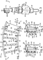
- FIG. 3 is a perspective view of an embodiment of a boundary layer rake assembly 70.
- the boundary layer rake assembly 70 includes a rake body 72, a tube 74, frame connector 76, tube adapter 78, tube adapter body 80, tube adapter 82, tube adapter 84, and tube 86.
- the rake body 72 further defines sensor apertures 88 and film cooling outlets 90.
- the apertures 88 enable sensors either within or external to the rake body 72 to collect measurements about the boundary layer, while the rake body 72 extends into the boundary layer flow (e.g., combustion gas flow).
- the cooling outlets 90 enable a shielding/cooling gas film (e.g., air cooling film) to protect the body 72.
- This cooling film may advantageously enable the rake body 72 to withstand temperatures above a melting temperature of the rake material.
- the rake body 72 may employ thermal management features such as film cooling, or impingement cooling, or a thermal barrier coating (TBC), or any combination thereof, to enable operation of the rake body 72 in a hot gas flow substantially about the melting temperature of the rake material.
- the thermal management features may protect the rake body 72 in hot gas temperatures greater than 1.1 to 10, 2 to 8, or 3 to 5 times the melting temperature of the rake material.
- the rake body 72 may be able to withstand temperatures up to, equal to, or above approximately 600, 700, 800, 900, 1000, 1100, 1200, 1300, 1400, or 1500 degrees Celsius or greater.
- these example temperatures are not intended to be limiting, as the ranges will change depending on the material composition of the rake body 72 and the thermal management features.
- a cooling airflow may pass through tube 86, tube adapter 84, body 80, adapter 78, connector 76, tube 74 and into rake body 72 where the cooling airflow cools the interior of the rake body 72 before exiting through the cooling outlets 90.
- the cooling air for the outlets 90 may flow through the tube adapter 82. Inside the rake body 72, the cooling airflow may impinge on the interior surface of the rake body 72 to provide impingement cooling.
- the frame connector 76 mounts the assembly 70 to the frame 44, the tube 74 extends through the wall 46 or 47, and the rake body 72 extends into the flow path 50.
- the rake body apertures 84 enable data collection (e.g., temperature, pressure, emissions, etc.) either with sensors in the apertures 84 or with sensors remote from the boundary layer rake assembly 70.
- the apertures 88 are positioned in close proximity to the wall 46 or 47, thereby enabling boundary layer measurements of the exhaust flow in the flow path.
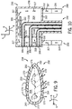
- FIG. 4 is a perspective view of an embodiment of a boundary layer rake 110.
- the rake 110 includes a body 112 and tube 114.
- the body 112 defmes a curved leading edge 116; curved trailing edge 118; side surfaces 120 and 122; a top surface 124; sensor apertures 126; and cooling outlets 128.
- the sensor apertures 126 are included on the leading edge 116.
- the sensor apertures 126 may be flush with the leading edge 116.
- the apertures 126 permit measurement of a fluid flow parameter (e.g., pressure, temperature, or emissions) with a probe or sensor in the rake body 112 or external to the rake body 112.
- the apertures 126 may enable the collection of combustion gases for analysis.
- the combustion gases may enter the rake body 112 through apertures 126 and then pass through the tube 114 to an analyzer.
- the combustion gases may be tested to determine the pressure, temperature, or emissions (e.g., pollutants such as carbon oxides, sulfur oxides, nitrogen oxides, or particulate matter) present in the flow.
- the apertures 126 may include the same or different sensors/probes.
- the sensors/probes in the apertures 126 may differ from one another (e.g., one aperture 126 may include an emissions probe, one aperture 126 may include a pressure probe, and one aperture 126 may include a temperature probe).
- the apertures 126 are separated from each other and from the walls 46, 47 (seen in FIG. 2 ) by radial distances 130, 132, and 134. As illustrated the distance 130 and 13 are between adjacent apertures 126 while the distances 134 is between the lower aperture 126 and the wall 46 or 47. In certain embodiments, the distances 130, 132, and 134 may be equal or different from one another. For example, the distances 130, 132, and 134 may progressively increase or progressively decrease radially 6 away from the wall 46 or 47. The distances 130, 132, and 134 enable measurement of pressure, temperature, or emissions at different locations in the boundary layer flow. Again, the distance 134 offsets the first probe/sensor from the walls 46, 47.
- This radial 6 distance 134 may be less than 1, 2, 3, 4, 5, 6, 7, 8, 9, or 10 percent of the total distance 54 between the walls 46 and 47. However, the radial distance 134 may be any suitable percentage of the total distance 54.
- the ability to measure the pressure, temperature, emissions, or other flow parameters in the boundary layer may advantageously assist in the design of improved hardware.
- the rake body 112 includes cooling outlets 128 along an exterior surface 129, e.g., leading edge 116, the side surfaces 120, 122, and the top surface 124 of the rake body 112.
- the outlets 128 enable cooling air to exit the rake body 112 to provide a cooling film that protects the rake body 112 from the high temperatures of the flow.
- the illustrated rake body 112 includes 30 cooling outlets 128 on each side surface 120 and 122, and 5 cooling outlets 128 on the top surface 124. In other embodiments, there may be any number of cooling outlets 128 on the leading edge 116, side surfaces 120, 122, and top surface 124.
- the rake body 112 may include 10 to 100 or 10 to 1000 cooling outlets 128 distributed over the various surfaces.
- the outlets 128 may form any number of sizes and shapes.
- the outlets 128 may be circular, oval, square, irregular, triangular, polygonal, or x-shaped.
- the outlets 128 may have a single shape, or a plurality of different shapes, distributed over the various surfaces.
- the outlets 128 may have a uniform or non-uniform spacing.
- the outlets 128 may be arranged in rows, columns, or various patterns.
- outlets 128 may have a variety of angles relative to the exterior surface 129, e.g., approximately 0 to 90, 5 to 75, 10 to 60, or 20 to 45 degrees.
- the angles may be greater or less than approximately 5, 10, 15, 20, 30, 45, or 60 degrees.
- FIG. 5 is a perspective view of an embodiment of a boundary layer rake 150.
- the rake 150 includes a body 152 and tube 154.
- the body 152 defmes a curved leading edge 156; curved trailing edge 158; side surfaces 160 and 162; a top surface 164; sensors 166; and cooling outlets 168.
- the sensors 166 protrude from the leading edge 156, such that the sensors 166 may be substantially surrounded by the fluid flow.
- the sensors 166 may include temperature sensors (e.g., thermocouples) or any other type of sensor. Thus, the sensors 166 (e.g., temperature sensors) may be used to measure the temperatures in the boundary layer of the fluid flow.
- the sensors 166 may be type B, K, or N thermocouples depending on the expected measurement temperatures. As illustrated, the sensors 166 are separated by distances 170 and 172. In the present embodiment, the distances 170 and 172 are equal in distance. In other embodiments, the distances 170 may be greater than or equal to the distance 172. The distances 170 and 172 between the sensors 166 permit temperature measurement at different locations in the flow, or more specifically the flow's boundary layer. The ability to measure the temperatures in the boundary layer may advantageously assist in the design of improved hardware.
- the cooling outlets 168 are on the leading edge 156, side surfaces 160, 162, top surface 164, and bottom surface.
- the outlets 168 advantageously permit cooling air to exit the rake body 152 to provide a cooling film that protects the rake body from the extreme temperatures of the flow.
- the outlets 168 may be circular, square, irregular, triangular, polygonal, in shape.
- the outlets 168 may have single shape or a plurality of shapes, distributed over the various surfaces.
- the outlets 168 may have uniform or non-uniform spacing.
- the outlets may be arranged in rows, columns, or various patterns.
- the outlets 168 may have a variety of angles relative to the exterior surface 129, e.g., 5 to 90 degrees.
- FIG. 6 is a cross-sectional side view of an embodiment of the boundary layer rake 110 of FIG. 4 .
- the rake 110 includes body 112 and tube 114.
- the body 112 includes the curved leading edge 116; curved trailing edge 118; side surface 122; top surface 124; sensor apertures 126; cooling outlets 128; conduits 190; thermal barrier coating (TBC) 192; and internal cooling path 194.
- the conduits 190 create a pathway between the apertures 126 and measurement equipment outside of the rake 110.
- the conduits 190 may channel a sample of the monitored fluid flow (e.g., combustion gases) to an external analyzer, which may analyze the sampled gases to determine temperature, pressure, emissions levels, or other parameters of the sampled gases.
- the conduits 190 route cables (e.g., electrical/data cables) between sensors mounted in the apertures 126 and external data analysis equipment.
- the rake 110 includes cooling outlets 128 to discharge a coolant fluid (e.g., a coolant gas) from the gas coolant path 194 to create a cooling film on the exterior surface 129 of the rake 110.
- a coolant fluid e.g., a coolant gas
- the cooling path 194 that supplies the cooling film travels through the tube 114 in the space between and around the tubes 190 until reaching the body 112, where the cooling path 194 impinges the coolant fluid against the interior surface 196 (e.g., impingement cooling) before exiting through the outlets 128.
- the coolant gas Once the coolant gas exits through the outlets 128, the coolant gas creates a cooling film along the exterior surface 129 to protect the rake 110 from high temperatures found in combustion gases.
- the cooling path 194 is configured to provide internal and external cooling of the rake 110.
- the impingement cooling of the interior surface 196 is particularly helpful in cooling the leading edge 116 of the rake 110.
- the film cooling provided by the cooling outlets 128 is particularly helpful in cooling and thermally shielding the remainder of the exterior surface 128, including side surfaces 120 and 122; top surface 124, and trailing edge 118.
- the cooling fluid may include a variety of gases, such as air, CO 2 , or N 2 .
- the cooling outlets 128 may have a variety of angles relative to the surface 129 to facilitate film cooling.
- each cooling outlet 128 may have a flow axis 197 at an angle 198 relative to the exterior surface 129, wherein the angle 198 may range between approximately 0 to 90 degrees in an upstream or downstream direction relative to the monitored flow (e.g., combustion gas flow).
- the thermal barrier coating 192 provides additional thermal protection for the rake 110.
- FIG. 7 is a partial cross-sectional side view of an embodiment of the boundary layer rake 110 along line 7-7 of FIG. 6 .
- the boundary layer rake 110 defines the top surface 124 with outlets 128.
- the outlets 128 enable a cooling gas (e.g., air) traveling through a hollow chamber 200 to create a cooling film over the top surface 124.
- the cooling film protects the boundary layer rake 110 as it collects data in the high temperature combustion gas flow.
- each outlet 128 has a flow axis 201 at an angle 202 with the exterior surface 129 and/or an axial axis 204 in the axial direction 4.
- the angle 202 of each flow axis 201 may be approximately 0 to 90, 5 to 75, 10 to 60, or 20 to 45 degrees.
- a plurality or all of the outlets 128 may have the same angle 202 relative to the exterior surface 129 or the axis 204.
- the angles 202 may differ from one outlet 128 to another.
- the angles 202 may progressively change (e.g., increase or decrease) in the axial direction 4, the radial direction 6, or the circumferential direction 8.
- the angle 202 of the outlets 128 along the top surface 124 are substantially equal, and may range between approximately 0 to 90, 5 to 75, 10 to 60 or 20 to 45 degrees.
- the angle 202 may range between approximately 30 to 60 degrees.
- the angle 202 of the outlet 128 may assist in directing the cooling film that protects the top surface 124 of the rake body 112.
- the outlets 128 on the side surfaces 120 and 122 may have equal or different angles as described above.
- FIG. 8 is a cross-sectional top view of an embodiment of the boundary layer rake 110 along line 8-8 of FIG. 6 .
- the rake 110 includes the body portion 112 that defines the leading edge/surface 116, the trailing edge/surface 118, and the side surfaces 120 and 122.
- the surfaces 116, 118, 120, and 122 enclose a cavity 230 that enables a cooling gas (e.g., air) to flow through the body 112 and exit through cooling outlets 128.
- a cooling gas e.g., air
- the cooling outlets 128 create a cooling film that protects the exterior surface 129 (including sides 120 and 122) of the body 112.
- each of the cooling outlets 128 includes an axis 232 that forms an angle 234 with respect to a longitudinal axis 236 along line 8-8 of FIG. 6 of the body 112.
- the angle 234 may be for example 0 to 90, 5 to 75, 10 to 60, or 20 to 45 degrees with respect to the centerline 236. In some embodiments, the angle 234 may vary from outlet 128 to outlet 128.
- some of the outlets 128 may define an angle 234 that increases or decreases with respect to other outlets 128, depending on the location of the outlet 128 on the surfaces 116, 118, 120, and 122.
- the angle 234 of the outlet 128 may assist in creating the cooling flow that protects the rake body 112.
- FIG. 9 is a top cross-sectional view of an embodiment of a boundary layer rake 256 along line 8-8 of FIG. 6 .
- the rake 256 includes a body portion 258 that defines an exterior surface 259, a leading edge 260, trailing edge 262, and side surfaces 264 and 266.
- the surfaces 260, 262, 264, and 266 enclose a cavity 268 that enables flow of a cooling gas (e.g., air) through the body 268 and out through cooling outlets 270.
- a cooling gas e.g., air
- the cooling outlets 270 create a cooling film that convectively cools and shields the exterior surface 259 (e.g., sides 264 and 266) of the body 258 from the high temperatures of the flow.
- each of the outlets 270 forms an angle 274 with respect to a longitudinal axis 276 of the body 258.
- the angle 274 may be for example 0 to 90, 5 to 75, 10 to 60, or 20 to 45 degrees with respect to the longitudinal axis 276.
- the angle 274 may vary from outlet 270 to outlet 270.
- some of the outlets 270 may define an angle 274 that is increases or decreases with respect to other outlets 270, depending on the location of the outlet 270 on the surfaces 260, 262, 264, and 266.
- the angle 274 of the outlet 270 may assist in creating the cooling flow that protects the rake body 258.
- the body 258 may form various shapes that may improve the aerodynamic flow of the combustion gases around the boundary layer rake 256. As illustrated, the body 258 has an airfoil shape, which may reduce resistance to the flow of combustion gases. In other embodiments, the body 258 may form other shapes including square, circular, oval, rectangular, triangular, or generally elongated.
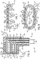
- FIG. 10 is a cross-sectional side view of an embodiment of a boundary layer rake 288, which includes a body 290, tube 292, and closed-loop cooling system 294.
- the body 290 defines a leading edge 296, trailing edge 298, a top surface 300, and bottom surface 302 that surround a hollow chamber 304.
- the leading edge 296 includes sensor apertures 306.
- the sensor apertures 306 permit communication between the combustion gas flow and measurement equipment external to the rake 288 through conduits 308.
- the conduits 308 may channel combustion gases to an external analyzer for an emissions analysis, temperature analysis, or pressure analysis.
- the conduits 308 may permit electrical communication between a thermocouple and exterior systems that track and store the measurements.
- the bottom surface 302 also defines a coolant entrance aperture 310 and a coolant exit aperture 312, which couple to the cooling system 294.
- the cooling system 294 includes a cooling supply pipe 314 and a cooling exit pipe 316.
- the coolant supply pipe 314 connects to a coolant supply (e.g., liquid or gas coolant supply) that supplies coolant for the system 294.
- the coolant supply may supply a variety of coolant fluids, such as air, CO 2 , N 2 , water, steam, other cooling liquids or gases, or any combination thereof.
- the coolant travels along a coolant path 317 from the coolant supply pipe 314, through the hollow chamber 304, and out through the coolant exit pipe 316. As the coolant travels along the coolant path 317, the coolant transfers heat away from the rake body 210 to protect the rake 288 from thermal damage.
- the coolant may enable the rake 288 to operate in hot fluid flows (e.g., combustion gases) substantially above a melting temperature of the rake material.
- the coolant flow may enable the rake 288 to operate in hot gas temperatures of greater than approximately 1.2, 2, 3, 4, 5, 6, 7, 8, 9, or 10 times the melting temperature of the rake material.
- the coolant flow is controlled with a baffle 318, which includes a first baffle portion 320 and a second baffle portion 322.
- the first baffle portion 320 directs the coolant flow along the leading edge 296.
- the second baffle portion 322 directs the coolant flow along the top surface 300 and toward the trailing edge 298.
- the coolant flow may then exit through the aperture 312 and enter pipe 316.
- the pipe 316 may then carry the heated coolant to a heat exchanger, where the coolant releases the absorbed heat before reentry into the coolant supply pipe 314.
- the cooling system 294 may be either a closed loop system or an open loop system in certain embodiments.
- the cooling system 294 may continuously receive a new supply of coolant, such as water, gas, steam, and so forth. Accordingly, the boundary layer rake 288 may be cooled with a liquid coolant to protect the rake 288 against thermal damage by the hot fluid flow.
- a boundary layer rake capable of measuring boundary layer properties, e.g., pressure, temperature, and emissions, in a high temperature combustion gas flow.
- the boundary layer rake is equipped with fluid cooling to withstand the high combustion gas temperatures.
- the fluid cooling may include gas or liquid cooling, and the fluid cooling may include impingement cooling, film cooling, and baffles to focus the cooling flow.
Landscapes
- Physics & Mathematics (AREA)
- General Physics & Mathematics (AREA)
- Engineering & Computer Science (AREA)
- Mechanical Engineering (AREA)
- General Engineering & Computer Science (AREA)
- Turbine Rotor Nozzle Sealing (AREA)
- Measuring Temperature Or Quantity Of Heat (AREA)
Abstract
A system, including, a boundary layer rake, including a rake body, a coolant path extending through the rake body, and a first probe coupled to the rake body, wherein the first probe is configured to measure a first parameter of a first boundary layer flow along a first wall.
Description
- The disclosed subject matter relates to turbomachinery, such as a gas turbine engine. More particularly, the disclosed subject matter relates to systems for measuring parameters of a fluid flow in various turbomachinery.
- The design and operation of turbomachinery, such as a gas turbine engine, may benefit from improved measurements of various parameters of a fluid flow. These measurements may relate to the temperature, pressure, flow rate, or emissions levels in the fluid flow. Unfortunately, existing systems do not provide boundary layer measurements within a boundary layer along a wall of the fluid flow. As a result, existing systems may not enable a complete or accurate analysis of the fluid flow, thereby resulting in less than optimal decisions for the design and operation of the turbomachinery.
- Certain embodiments commensurate in scope with the originally claimed invention are summarized below. These embodiments are not intended to limit the scope of the claimed invention, but rather these embodiments are intended only to provide a brief summary of possible forms of the invention. Indeed, the invention may encompass a variety of forms that may be similar to or different from the embodiments set forth below.
- In a first aspect, the invention resides in a system including a flow path rake, including a rake body, a coolant path extending through the rake body, and a first probe coupled to the rake body, wherein the first probe is configured to measure a first parameter of a flow along a flow path.
- The flow path rake may be a boundary layer rake, and wherein the first probe is configured to measure a first parameter of a first boundary layer flow along a first wall.
- The coolant path may comprise a gas coolant path comprising a plurality of film cooling outlets in the rake body.
- Embodiments of the present invention will now be described, by way of example only, with reference to the accompanying drawings in which:
-
FIG. 1 is a schematic flow diagram of an embodiment of a gas turbine engine that may employ a boundary layer rake; -
FIG. 2 is a front view of an embodiment of a test assembly with boundary layer rakes; -
FIG. 3 is a perspective view of an embodiment of a boundary layer rake assembly; -
FIG. 4 is a perspective view of an embodiment of a pressure or emissions measuring boundary layer rake; -
FIG. 5 is a perspective view of an embodiment of a temperature measuring boundary layer rake; -
FIG. 6 is a cross-sectional side view of an embodiment of the boundary layer rake inFIG. 4 ; -
FIG. 7 is a partial cross-sectional side view of an embodiment of a boundary layer rake along line 7-7 ofFIG. 6 ; -
FIG. 8 is a cross-sectional top view of an embodiment of a boundary layer rake along line 8-8 ofFIG. 6 ; -
FIG. 9 is a cross-sectional top view of an embodiment of a boundary layer rake along line 8-8 ofFIG. 6 ; and -
FIG. 10 is a cross-sectional side view of an embodiment of a boundary layer rake. - One or more specific embodiments of the present invention will be described below. In an effort to provide a concise description of these embodiments, all features of an actual implementation may not be described in the specification. It should be appreciated that in the development of any such actual implementation, as in any engineering or design project, numerous implementation-specific decisions must be made to achieve the developers' specific goals, such as compliance with system-related and business-related constraints, which may vary from one implementation to another. Moreover, it should be appreciated that such a development effort might be complex and time consuming, but would nevertheless be a routine undertaking of design, fabrication, and manufacture for those of ordinary skill having the benefit of this disclosure.
- When introducing elements of various embodiments of the present invention, the articles "a," "an," "the," and "said" are intended to mean that there are one or more of the elements. The terms "comprising," "including," and "having" are intended to be inclusive and mean that there may be additional elements other than the listed elements.
- As discussed in detail below, the disclosed embodiments enable near wall measurements within a boundary layer along a wall of a fluid flow using a boundary layer rake. The boundary layer measurements supplement primary measurements by a primary rake extending across the fluid flow, thereby enabling a more complete analysis and model of the fluid flow. These measurements may relate to the temperature, pressure, flow rate, pollutant emissions levels, smoke levels, flame presence, gas composition, or any other parameter of the fluid flow. In certain embodiments, the boundary layer rake and the primary rake may be used to acquire measurements in a combustor or a turbine of a gas turbine engine. As a result of the disclosed embodiments, the improved analysis and model of the fluid flow may enable improved decisions for the design and operation of various turbomachinery, such as the gas turbine engine. Furthermore, the disclosed embodiments of the rake may be used in various test rigs with a high temperature flow path, combustion test stands that simulate a single combustor section of a gas turbine, or any other flow path benefiting from boundary layer measurements. In addition, the disclosed embodiments may provide a coolant path through the boundary layer rake and the primary rake. For example, the coolant path may be configured to circulate a coolant fluid (e.g., a liquid or gas coolant) through the boundary layer rake and the primary rake, thereby protecting the rake from damage due to heat in the fluid flow, e.g., hot combustion products. By further example, the coolant path may lead to outlet ports or vents (e.g., film cooling orifices) in the boundary layer rake and the primary rake, thereby allowing at least some of the coolant to exit from the rake into the fluid flow. The discharged coolant may flow at partially along an external surface of the boundary layer rake and the primary rake to provide thermal shielding and cooling of the external surface (e.g., film cooling). Accordingly, the disclosed embodiments improve the acquisition of data in various fluid flows, such as flows of hot combustion products.
- Turning now to the drawings,
FIG. 1 is a schematic flow diagram of an embodiment of asystem 10 with agas turbine 12 that may employ a near wall rake or boundary layer rake. As discussed below, the rear wall rake may be disposed along a wall within a boundary layer of a fluid flow to improve measurements of the fluid flow. In the following discussion, reference may be made to an axial direction oraxis 4, a radial direction oraxis 6, and a circumferential direction oraxis 8 to define orientations of various components, such as the boundary layer rakes. In certain embodiments, thesystem 10 may include an aircraft, a watercraft, a locomotive, a power generation system, or combinations thereof. The illustratedgas turbine engine 12 includes anair intake section 16, acompressor 18, acombustor section 20, aturbine 22, and anexhaust section 24. Theturbine 22 is coupled to thecompressor 18 via ashaft 26. - As indicated by the arrows, air may enter the
gas turbine engine 12 through theintake section 16 and flow into thecompressor 18, which compresses the air prior to entry into thecombustor section 20. The illustratedcombustor section 20 includes acombustor housing 28 disposed concentrically or annularly about theshaft 26 between thecompressor 18 and theturbine 22. The compressed air from thecompressor 18 enterscombustors 30, where the compressed air may mix and combust with fuel within thecombustors 30 to drive theturbine 22. From thecombustor section 20, the hot combustion gases flow through theturbine 22, driving thecompressor 18 via theshaft 26. For example, the combustion gases may apply motive forces to turbine rotor blades within theturbine 22 to rotate theshaft 26. After flowing through theturbine 22, the hot combustion gases may exit thegas turbine engine 12 through theexhaust section 24. -
FIG. 2 is a front view of an embodiment of atest assembly 40 with near wall rakes orboundary layer rakes 42,primary rakes 44, and aframe 45. Theframe 45 defmes afirst wall 46 and asecond wall 47. Therakes apertures 48. In some embodiments, theapertures 48 permit the placement of probes or sensors in theflow path 50 of a fluid flow, such as hot combustion gases in thegas turbine engine 12 ofFIG. 1 . The sensors may include temperature sensors, pressure sensors, flow rate sensors, emissions sensors, or any combination thereof. For example, each probe may include a single type of measurement sensor, or each probe may be multifunctional with multiple types of measurement sensors. In other embodiments, theapertures 48 permit removal of combustion gases from the flow and into an analyzer with sensors that measure parameters of the fluid flow, such as emissions of pollutants such as carbon oxides, sulfur oxides, nitrogen oxides, or particulate matter. In particular, the sensors may permit more accurate modeling of the fluid flow (e.g., combustion products) enabling better and more robust hardware designs for the turbomachinery, such as gas turbine engines. - As illustrated, the
primary rakes 44 are positioned in theflow path 50 and run the entire distance 54 between thewalls frame 45. Therakes 44 are able to measure fluid flow properties away from thewalls walls apertures 48 of the boundary layer rakes 42 are positioned within the boundary layers along thewalls walls radial distance 52, which is substantially less than a total radial distance 54 between thewalls radial distance 52 may be less than approximately 5, 10, 15, 20, 25, or 30 percent of the total distance 54 between thewalls radial distance 52 may be less than approximately 1, 2, 3, 4, 5, 6, 7, 8, 9, or 10 percent of the total distance 54. However, the boundary layer rakes 42 may be used at anyradial distance 52 between 0 and 100 percent of the total distance 54. Similarly, eachaperture 48 may be disposed at a radial distance of between approximately 1 to 15 percent of the total distance 54. For example, in the illustrated embodiment, eachboundary layer rake 42 includes threeapertures 48, which may be disposed at radial distances of approximately 1 to 5, 2 to 10, and 3 to 15 percent (e.g., , 8, and 12 percent) of the total distance 54, respectively. However, theapertures 48 may be disposed at any suitable radial distance within a boundary layer, such as approximately 1, 2, 3, 4, 5, 6, 7, 8, 9, 10, 11, 12, 13, 14, and/or 15 percent of the total distance 54. This positioning may advantageously permit a more accurate measurement of the flow's boundary layer. A better understanding of the flow's boundary layer may assist in the design of more robust hardware, because it is the boundary layer that interacts with the walls and hardware of the turbomachinery (e.g., gas turbine engine 12). - In the embodiment of
FIG. 2 , a singleboundary layer rake 42 is positioned between each pair of adjacent primary rakes 44 on thefirst wall 46 and each pair of adjacent primary rakes 44 on thesecond wall 47. In other embodiments, (e.g., 2, 3, 4, 5, or more) multiple boundary layer rakes 42 may be positioned between each pair of adjacent primary rakes 44 on the first andsecond walls rakes 44, wherein the boundary layer rakes 42 are either axially 4 in-line with or circumferentially 8 between therakes 44. Thus, therakes walls apertures 48 across thefluid flow path 50. Theapertures 48 may be spaced the same or different on the boundary layer rakes 42 and the primary rakes 44. For example, aradial 6 spacing betweenapertures 48 on the boundary layer rakes 42 may be less than approximately 10, 20, 30, 40, 50, 60, 70, 80, or 90 percent of a radial 6 spacing betweenapertures 48 on the primary rakes 44. In certain embodiments, theapertures 48 on the boundary layer rakes 42 may have a radial 6 spacing of approximately 10 to 50 or 20 to 40 percent of a radial 6 spacing betweenapertures 48 on the primary rakes 44. However, anysuitable radial 6 spacing may be used for theapertures 48 on therakes - In the illustrated embodiment, the boundary layer rakes 42 and the primary rakes 44 include an internal coolant passage to flow a coolant fluid (e.g., gas or liquid) through the
rakes rakes rakes rakes -
FIG. 3 is a perspective view of an embodiment of a boundarylayer rake assembly 70. The boundarylayer rake assembly 70 includes arake body 72, atube 74,frame connector 76,tube adapter 78,tube adapter body 80,tube adapter 82, tube adapter 84, andtube 86. Therake body 72 further definessensor apertures 88 andfilm cooling outlets 90. Theapertures 88 enable sensors either within or external to therake body 72 to collect measurements about the boundary layer, while therake body 72 extends into the boundary layer flow (e.g., combustion gas flow). In order for therake body 72 to withstand the high temperatures of the combustion gases, the coolingoutlets 90 enable a shielding/cooling gas film (e.g., air cooling film) to protect thebody 72. This cooling film, along with other thermal management features, may advantageously enable therake body 72 to withstand temperatures above a melting temperature of the rake material. For example, as discussed below, therake body 72 may employ thermal management features such as film cooling, or impingement cooling, or a thermal barrier coating (TBC), or any combination thereof, to enable operation of therake body 72 in a hot gas flow substantially about the melting temperature of the rake material. In particular, the thermal management features may protect therake body 72 in hot gas temperatures greater than 1.1 to 10, 2 to 8, or 3 to 5 times the melting temperature of the rake material. Thus, depending on the material composition of therake body 72 and the thermal management features, therake body 72 may be able to withstand temperatures up to, equal to, or above approximately 600, 700, 800, 900, 1000, 1100, 1200, 1300, 1400, or 1500 degrees Celsius or greater. However, these example temperatures are not intended to be limiting, as the ranges will change depending on the material composition of therake body 72 and the thermal management features. In certain embodiments, a cooling airflow may pass throughtube 86, tube adapter 84,body 80,adapter 78,connector 76,tube 74 and intorake body 72 where the cooling airflow cools the interior of therake body 72 before exiting through the coolingoutlets 90. In some embodiments, the cooling air for theoutlets 90 may flow through thetube adapter 82. Inside therake body 72, the cooling airflow may impinge on the interior surface of therake body 72 to provide impingement cooling. - In the illustrated embodiment, the
frame connector 76 mounts theassembly 70 to theframe 44, thetube 74 extends through thewall rake body 72 extends into theflow path 50. With therake body 72 firmly anchored in theframe 44, the rake body apertures 84 enable data collection (e.g., temperature, pressure, emissions, etc.) either with sensors in the apertures 84 or with sensors remote from the boundarylayer rake assembly 70. In either case, theapertures 88 are positioned in close proximity to thewall -
FIG. 4 is a perspective view of an embodiment of aboundary layer rake 110. Therake 110 includes abody 112 andtube 114. Thebody 112 defmes a curvedleading edge 116;curved trailing edge 118; side surfaces 120 and 122; atop surface 124;sensor apertures 126; and coolingoutlets 128. As illustrated, thesensor apertures 126 are included on theleading edge 116. For example, thesensor apertures 126 may be flush with theleading edge 116. Theapertures 126 permit measurement of a fluid flow parameter (e.g., pressure, temperature, or emissions) with a probe or sensor in therake body 112 or external to therake body 112. For example, theapertures 126 may enable the collection of combustion gases for analysis. The combustion gases may enter therake body 112 throughapertures 126 and then pass through thetube 114 to an analyzer. In the analyzer, the combustion gases may be tested to determine the pressure, temperature, or emissions (e.g., pollutants such as carbon oxides, sulfur oxides, nitrogen oxides, or particulate matter) present in the flow. In some embodiments, theapertures 126 may include the same or different sensors/probes. For example, the sensors/probes in theapertures 126 may differ from one another (e.g., oneaperture 126 may include an emissions probe, oneaperture 126 may include a pressure probe, and oneaperture 126 may include a temperature probe). - Furthermore, the
apertures 126 are separated from each other and from thewalls 46, 47 (seen inFIG. 2 ) byradial distances distance 130 and 13 are betweenadjacent apertures 126 while thedistances 134 is between thelower aperture 126 and thewall distances distances wall distances distance 134 offsets the first probe/sensor from thewalls distance 134 may be less than 1, 2, 3, 4, 5, 6, 7, 8, 9, or 10 percent of the total distance 54 between thewalls radial distance 134 may be any suitable percentage of the total distance 54. The ability to measure the pressure, temperature, emissions, or other flow parameters in the boundary layer may advantageously assist in the design of improved hardware. - As illustrated, the
rake body 112 includes coolingoutlets 128 along anexterior surface 129, e.g., leadingedge 116, the side surfaces 120, 122, and thetop surface 124 of therake body 112. Theoutlets 128 enable cooling air to exit therake body 112 to provide a cooling film that protects therake body 112 from the high temperatures of the flow. The illustratedrake body 112 includes 30 coolingoutlets 128 on eachside surface cooling outlets 128 on thetop surface 124. In other embodiments, there may be any number of coolingoutlets 128 on theleading edge 116, side surfaces 120, 122, andtop surface 124. For example, therake body 112 may include 10 to 100 or 10 to 1000cooling outlets 128 distributed over the various surfaces. In addition, theoutlets 128 may form any number of sizes and shapes. For example, theoutlets 128 may be circular, oval, square, irregular, triangular, polygonal, or x-shaped. In some embodiments, theoutlets 128 may have a single shape, or a plurality of different shapes, distributed over the various surfaces. In still other embodiments, theoutlets 128 may have a uniform or non-uniform spacing. For example, theoutlets 128 may be arranged in rows, columns, or various patterns. Furthermore, theoutlets 128 may have a variety of angles relative to theexterior surface 129, e.g., approximately 0 to 90, 5 to 75, 10 to 60, or 20 to 45 degrees. For example, the angles may be greater or less than approximately 5, 10, 15, 20, 30, 45, or 60 degrees. -
FIG. 5 is a perspective view of an embodiment of aboundary layer rake 150. Therake 150 includes abody 152 andtube 154. Thebody 152 defmes a curvedleading edge 156;curved trailing edge 158; side surfaces 160 and 162; atop surface 164;sensors 166; and coolingoutlets 168. As illustrated, thesensors 166 protrude from theleading edge 156, such that thesensors 166 may be substantially surrounded by the fluid flow. Thesensors 166 may include temperature sensors (e.g., thermocouples) or any other type of sensor. Thus, the sensors 166 (e.g., temperature sensors) may be used to measure the temperatures in the boundary layer of the fluid flow. For example, thesensors 166 may be type B, K, or N thermocouples depending on the expected measurement temperatures. As illustrated, thesensors 166 are separated bydistances distances distances 170 may be greater than or equal to thedistance 172. Thedistances sensors 166 permit temperature measurement at different locations in the flow, or more specifically the flow's boundary layer. The ability to measure the temperatures in the boundary layer may advantageously assist in the design of improved hardware. - As illustrated, the cooling
outlets 168 are on theleading edge 156, side surfaces 160, 162,top surface 164, and bottom surface. Theoutlets 168 advantageously permit cooling air to exit therake body 152 to provide a cooling film that protects the rake body from the extreme temperatures of the flow. As illustrated, there are 35outlets 168 that are circular in shape and arranged into rows. Similar to the discussion above with respect toFIG. 4 , there may any number of outlets on theleading edge 156, side surfaces 160, 162, andtop surface 164. For example, there may be 10 to 100 or 10 to 1000cooling outlets 168 distributed over the various surfaces. In addition, theoutlets 168 may form any number of sizes and shapes. For example, theoutlets 168 may be circular, square, irregular, triangular, polygonal, in shape. Theoutlets 168 may have single shape or a plurality of shapes, distributed over the various surfaces. In still other embodiments, theoutlets 168 may have uniform or non-uniform spacing. For example, the outlets may be arranged in rows, columns, or various patterns. Furthermore, theoutlets 168 may have a variety of angles relative to theexterior surface 129, e.g., 5 to 90 degrees. -
FIG. 6 is a cross-sectional side view of an embodiment of theboundary layer rake 110 ofFIG. 4 . Therake 110 includesbody 112 andtube 114. Thebody 112 includes the curvedleading edge 116;curved trailing edge 118;side surface 122;top surface 124;sensor apertures 126; coolingoutlets 128;conduits 190; thermal barrier coating (TBC) 192; andinternal cooling path 194. Theconduits 190 create a pathway between theapertures 126 and measurement equipment outside of therake 110. In one embodiment, theconduits 190 may channel a sample of the monitored fluid flow (e.g., combustion gases) to an external analyzer, which may analyze the sampled gases to determine temperature, pressure, emissions levels, or other parameters of the sampled gases. In another embodiment, theconduits 190 route cables (e.g., electrical/data cables) between sensors mounted in theapertures 126 and external data analysis equipment. - As explained above, the
rake 110 includes coolingoutlets 128 to discharge a coolant fluid (e.g., a coolant gas) from thegas coolant path 194 to create a cooling film on theexterior surface 129 of therake 110. Thecooling path 194 that supplies the cooling film travels through thetube 114 in the space between and around thetubes 190 until reaching thebody 112, where thecooling path 194 impinges the coolant fluid against the interior surface 196 (e.g., impingement cooling) before exiting through theoutlets 128. Once the coolant gas exits through theoutlets 128, the coolant gas creates a cooling film along theexterior surface 129 to protect therake 110 from high temperatures found in combustion gases. Thus, thecooling path 194 is configured to provide internal and external cooling of therake 110. The impingement cooling of theinterior surface 196 is particularly helpful in cooling theleading edge 116 of therake 110. Furthermore, the film cooling provided by the coolingoutlets 128 is particularly helpful in cooling and thermally shielding the remainder of theexterior surface 128, including side surfaces 120 and 122;top surface 124, and trailingedge 118. As appreciated, the cooling fluid may include a variety of gases, such as air, CO2, or N2. Furthermore, the coolingoutlets 128 may have a variety of angles relative to thesurface 129 to facilitate film cooling. For example, each coolingoutlet 128 may have aflow axis 197 at anangle 198 relative to theexterior surface 129, wherein theangle 198 may range between approximately 0 to 90 degrees in an upstream or downstream direction relative to the monitored flow (e.g., combustion gas flow). Thethermal barrier coating 192 provides additional thermal protection for therake 110. -
FIG. 7 is a partial cross-sectional side view of an embodiment of theboundary layer rake 110 along line 7-7 ofFIG. 6 . Theboundary layer rake 110 defines thetop surface 124 withoutlets 128. Theoutlets 128 enable a cooling gas (e.g., air) traveling through ahollow chamber 200 to create a cooling film over thetop surface 124. The cooling film protects theboundary layer rake 110 as it collects data in the high temperature combustion gas flow. As illustrated, eachoutlet 128 has aflow axis 201 at anangle 202 with theexterior surface 129 and/or anaxial axis 204 in theaxial direction 4. For example, theangle 202 of eachflow axis 201 may be approximately 0 to 90, 5 to 75, 10 to 60, or 20 to 45 degrees. In some embodiments, a plurality or all of theoutlets 128 may have thesame angle 202 relative to theexterior surface 129 or theaxis 204. In other embodiments, theangles 202 may differ from oneoutlet 128 to another. For example, theangles 202 may progressively change (e.g., increase or decrease) in theaxial direction 4, theradial direction 6, or thecircumferential direction 8. In the illustrated embodiment, theangle 202 of theoutlets 128 along thetop surface 124 are substantially equal, and may range between approximately 0 to 90, 5 to 75, 10 to 60 or 20 to 45 degrees. For example, theangle 202 may range between approximately 30 to 60 degrees. Theangle 202 of theoutlet 128 may assist in directing the cooling film that protects thetop surface 124 of therake body 112. Similarly, theoutlets 128 on the side surfaces 120 and 122 may have equal or different angles as described above. -
FIG. 8 is a cross-sectional top view of an embodiment of theboundary layer rake 110 along line 8-8 ofFIG. 6 . Therake 110 includes thebody portion 112 that defines the leading edge/surface 116, the trailing edge/surface 118, and the side surfaces 120 and 122. Thesurfaces cavity 230 that enables a cooling gas (e.g., air) to flow through thebody 112 and exit through coolingoutlets 128. As explained above, the coolingoutlets 128 create a cooling film that protects the exterior surface 129 (includingsides 120 and 122) of thebody 112. The cooling film both convectively cools theexterior surface 129 and shielded theexterior surface 129 from direct contact with the monitored flow (e.g., hot combustion gas flow). Thus, the film cooling increases the use and longevity of theboundary layer rake 110 in harsh environments, such as combustion systems. As illustrated, each of the coolingoutlets 128 includes anaxis 232 that forms anangle 234 with respect to alongitudinal axis 236 along line 8-8 ofFIG. 6 of thebody 112. Theangle 234 may be for example 0 to 90, 5 to 75, 10 to 60, or 20 to 45 degrees with respect to thecenterline 236. In some embodiments, theangle 234 may vary fromoutlet 128 tooutlet 128. For example, some of theoutlets 128 may define anangle 234 that increases or decreases with respect toother outlets 128, depending on the location of theoutlet 128 on thesurfaces angle 234 of theoutlet 128 may assist in creating the cooling flow that protects therake body 112. -
FIG. 9 is a top cross-sectional view of an embodiment of aboundary layer rake 256 along line 8-8 ofFIG. 6 . Therake 256 includes abody portion 258 that defines anexterior surface 259, aleading edge 260, trailingedge 262, andside surfaces surfaces cavity 268 that enables flow of a cooling gas (e.g., air) through thebody 268 and out through coolingoutlets 270. As explained above, the coolingoutlets 270 create a cooling film that convectively cools and shields the exterior surface 259 (e.g., sides 264 and 266) of thebody 258 from the high temperatures of the flow. This ability increases the longevity of theboundary layer rake 110 while enabling measurement of pressure, emissions, and temperature with a sensor/probe that communicates with a flow throughaperture 272. As illustrated each of theoutlets 270 forms anangle 274 with respect to alongitudinal axis 276 of thebody 258. Theangle 274 may be for example 0 to 90, 5 to 75, 10 to 60, or 20 to 45 degrees with respect to thelongitudinal axis 276. In some embodiments, theangle 274 may vary fromoutlet 270 tooutlet 270. For example, some of theoutlets 270 may define anangle 274 that is increases or decreases with respect toother outlets 270, depending on the location of theoutlet 270 on thesurfaces angle 274 of theoutlet 270 may assist in creating the cooling flow that protects therake body 258. Furthermore, thebody 258 may form various shapes that may improve the aerodynamic flow of the combustion gases around theboundary layer rake 256. As illustrated, thebody 258 has an airfoil shape, which may reduce resistance to the flow of combustion gases. In other embodiments, thebody 258 may form other shapes including square, circular, oval, rectangular, triangular, or generally elongated. -
FIG. 10 is a cross-sectional side view of an embodiment of aboundary layer rake 288, which includes abody 290,tube 292, and closed-loop cooling system 294. Thebody 290 defines aleading edge 296, trailingedge 298, atop surface 300, andbottom surface 302 that surround ahollow chamber 304. As illustrated, theleading edge 296 includessensor apertures 306. Thesensor apertures 306 permit communication between the combustion gas flow and measurement equipment external to therake 288 throughconduits 308. For example, theconduits 308 may channel combustion gases to an external analyzer for an emissions analysis, temperature analysis, or pressure analysis. In other embodiments, theconduits 308 may permit electrical communication between a thermocouple and exterior systems that track and store the measurements. Thebottom surface 302 also defines acoolant entrance aperture 310 and acoolant exit aperture 312, which couple to thecooling system 294. - The
cooling system 294 includes acooling supply pipe 314 and acooling exit pipe 316. Thecoolant supply pipe 314 connects to a coolant supply (e.g., liquid or gas coolant supply) that supplies coolant for thesystem 294. The coolant supply may supply a variety of coolant fluids, such as air, CO2, N2, water, steam, other cooling liquids or gases, or any combination thereof. In operation, the coolant travels along acoolant path 317 from thecoolant supply pipe 314, through thehollow chamber 304, and out through thecoolant exit pipe 316. As the coolant travels along thecoolant path 317, the coolant transfers heat away from the rake body 210 to protect therake 288 from thermal damage. For example, the coolant may enable therake 288 to operate in hot fluid flows (e.g., combustion gases) substantially above a melting temperature of the rake material. In certain embodiments, the coolant flow may enable therake 288 to operate in hot gas temperatures of greater than approximately 1.2, 2, 3, 4, 5, 6, 7, 8, 9, or 10 times the melting temperature of the rake material. Inside thecavity 304, the coolant flow is controlled with abaffle 318, which includes afirst baffle portion 320 and asecond baffle portion 322. Thefirst baffle portion 320 directs the coolant flow along theleading edge 296. Thus, the hottest portion of therake 110 is cooled before other portions of therake body 290. After thefirst baffle portion 320 focuses the coolant flow along theleading edge 296, thesecond baffle portion 322 directs the coolant flow along thetop surface 300 and toward the trailingedge 298. After convectively cooling the trailingedge 298, the coolant flow may then exit through theaperture 312 and enterpipe 316. Thepipe 316 may then carry the heated coolant to a heat exchanger, where the coolant releases the absorbed heat before reentry into thecoolant supply pipe 314. However, thecooling system 294 may be either a closed loop system or an open loop system in certain embodiments. For example, thecooling system 294 may continuously receive a new supply of coolant, such as water, gas, steam, and so forth. Accordingly, theboundary layer rake 288 may be cooled with a liquid coolant to protect therake 288 against thermal damage by the hot fluid flow. - Technical effects of the invention include a boundary layer rake capable of measuring boundary layer properties, e.g., pressure, temperature, and emissions, in a high temperature combustion gas flow. The boundary layer rake is equipped with fluid cooling to withstand the high combustion gas temperatures. As explained above, the fluid cooling may include gas or liquid cooling, and the fluid cooling may include impingement cooling, film cooling, and baffles to focus the cooling flow.
- This written description uses examples to disclose the invention, including the best mode, and also to enable any person skilled in the art to practice the invention, including making and using any devices or systems and performing any incorporated methods. The patentable scope of the invention is defmed by the claims, and may include other examples that occur to those skilled in the art. Such other examples are intended to be within the scope of the claims if they have structural elements that do not differ from the literal language of the claims, or if they include equivalent structural elements with insubstantial differences from the literal language of the claims.
Claims (15)
- A system, comprising:a flow path rake (70,110), comprising:a rake body (72,112);a coolant path (194) extending through the rake body (72,112), and a first probe (166) coupled to the rake body (72,112), wherein the first probe is configured to measure a first parameter of a flow along a flow path.
- The system of claim 1, wherein the flow path rake is a boundary layer rake., and wherein the first probe (166) is configured to measure a first parameter of a first boundary layer flow along a first wall.
- The system of claim 2, wherein the first probe comprises a first probe location at a first offset distance (134) from the first wall (46), and the first offset distance is less than approximately 25 percent of a total distance (54) between the first wall (46) and a second wall (47) opposite from the first wall (46).
- The system of claim 2, wherein the coolant path comprises a liquid coolant path.
- The system of claim 1 or 2, wherein the coolant path comprises a gas coolant path.
- The system of claim 5, wherein the gas coolant path comprises a plurality of film cooling outlets (128) in the rake body (112).
- The system of claim 6, wherein each film cooling outlet (128) of the plurality of film cooling outlets has an axis at an angle of less than approximately 90 degrees relative to an exterior surface (129) of the rake body (112).
- The system of claim 6, wherein the rake body comprises a leading edge (116), a trailing edge (118), and a longitudinal axis extending from the leading edge (116) to the trailing edge (118), wherein a first set of the plurality of film cooling outlets comprises first axes that are angled approximately 90 degrees relative to the longitudinal axis, and a second set of the plurality of film cooling outlets comprises second axes that are angled less than approximately 90 degrees relative to the longitudinal axis in a downstream direction.
- The system of any preceding claim, wherein the rake body comprises a wall disposed about a hollow chamber, the coolant path extends through the hollow chamber, and the coolant path is configured to impinge a coolant flow against an interior surface of the wall.
- The system of claim 9, wherein the rake body comprises a leading edge and a trailing edge defined by the wall, and the coolant path is configured to impinge the coolant flow against the interior surface along the leading edge.
- The system of any preceding claim, wherein the first probe comprises an opening (126), a tube, or a sensor disposed along a leading edge (116) of the rake body (112).
- The system of any preceding claim, comprising a second probe coupled to the rake body, wherein the second probe is configured to measure a second parameter of the first boundary layer flow along the first wall (46).
- The system of claim 12, comprising a third probe coupled to the rake body, wherein the third probe is configured to measure a third parameter of the first boundary layer flow along the first wall (46).
- The system of any preceding claim, wherein the first probe comprises a temperature probe, a pressure probe, or an emissions probe, or a combination thereof.
- The system of any preceding claim, wherein the coolant path is configured to cool the flow path rake sufficiently to withstand temperatures of greater than approximately 600 degrees Celsius.
Applications Claiming Priority (1)
| Application Number | Priority Date | Filing Date | Title |
|---|---|---|---|
| US13/035,668 US20120216608A1 (en) | 2011-02-25 | 2011-02-25 | System for measuring parameters of fluid flow in turbomachinery |
Publications (1)
| Publication Number | Publication Date |
|---|---|
| EP2492441A2 true EP2492441A2 (en) | 2012-08-29 |
Family
ID=45656711
Family Applications (1)
| Application Number | Title | Priority Date | Filing Date |
|---|---|---|---|
| EP12156954A Withdrawn EP2492441A2 (en) | 2011-02-25 | 2012-02-24 | System for measuring parameters of fluid flow in turbomachinery |
Country Status (3)
| Country | Link |
|---|---|
| US (1) | US20120216608A1 (en) |
| EP (1) | EP2492441A2 (en) |
| CN (1) | CN102650571A (en) |
Cited By (6)
| Publication number | Priority date | Publication date | Assignee | Title |
|---|---|---|---|---|
| FR3025885A1 (en) * | 2014-09-15 | 2016-03-18 | Snecma | DEVICE FOR MEASURING AERODYNAMIC SIZES FOR PLACING IN A FLOWING VEHIC OF A TURBOMACHINE |
| FR3064745A1 (en) * | 2017-03-31 | 2018-10-05 | Safran Aircraft Engines | DEVICE FOR MEASURING CHARACTERISTICS OF AN AIR FLOW |
| US10871402B2 (en) | 2017-03-31 | 2020-12-22 | Safran Aircraft Engines | Device for measuring the characteristics of an air flow |
| AT525548B1 (en) * | 2021-11-22 | 2023-05-15 | Avl List Gmbh | sampling device |
| CN118111714A (en) * | 2024-03-05 | 2024-05-31 | 北京理工大学 | A high-precision measurement device and method for high-load turbine boundary layer |
| FR3149088A1 (en) * | 2023-05-25 | 2024-11-29 | Safran Aircraft Engines | Device for measuring air flow in a turbomachine vein |
Families Citing this family (14)
| Publication number | Priority date | Publication date | Assignee | Title |
|---|---|---|---|---|
| US8839662B2 (en) * | 2011-06-27 | 2014-09-23 | United Technologies Corporation | Station probe for gas turbine engines |
| US9442022B2 (en) * | 2011-12-30 | 2016-09-13 | Unison Industries, Llc | Temperature sensing device and method of assembling the same |
| EP2959137B1 (en) * | 2013-02-25 | 2017-11-29 | United Technologies Corporation | Modular instrumentation egress seal assembly for a gas turbine engine |
| US9116051B2 (en) * | 2013-03-07 | 2015-08-25 | United Technologies Corporation | Actively cooled gas turbine sensor probe housing |
| US10329921B2 (en) * | 2014-10-24 | 2019-06-25 | United Technologies Corporation | Cooling configuration for a component |
| DE102016204764B4 (en) * | 2016-03-22 | 2020-04-23 | Mtu Friedrichshafen Gmbh | Measuring device, fuel gas supply device with such a measuring device and internal combustion engine with such a fuel gas supply device |
| CN107727258B (en) * | 2017-09-15 | 2019-05-21 | 中国科学院工程热物理研究所 | A kind of probe reinforcing cooling structure |
| EP3462153B1 (en) * | 2017-09-29 | 2021-09-22 | General Electric Technology GmbH | Method for determining a local hot gas temperature in a hot gas duct, and devices for carrying out the method |
| US10598041B2 (en) | 2017-10-20 | 2020-03-24 | United Technologies Corporation | Inlet performance measurement system for gas turbine engine |
| US10684183B2 (en) * | 2018-04-24 | 2020-06-16 | The Boeing Company | Powered total pressure measurement rake with telemetry |
| JP7088751B2 (en) * | 2018-06-15 | 2022-06-21 | 矢崎総業株式会社 | Mounting structure of smoke exhaust temperature sensor |
| CN112524383B (en) * | 2020-11-17 | 2022-04-19 | 中国航发四川燃气涡轮研究院 | Axial expansion self-compensating device for aircraft engine turbine part tester |
| CN112729839B (en) * | 2020-12-15 | 2022-11-11 | 北京动力机械研究所 | Combustion measurement structure under large gas flow using condition |
| US12092025B2 (en) | 2021-12-22 | 2024-09-17 | Unison Industries, Llc | Turbine engine exhaust gas temperature sensor |
Family Cites Families (8)
| Publication number | Priority date | Publication date | Assignee | Title |
|---|---|---|---|---|
| US4747700A (en) * | 1987-06-19 | 1988-05-31 | Teledyne Industries, Inc. | Thermocouple rake |
| US5259234A (en) * | 1992-03-09 | 1993-11-09 | General Electric Company | Calibration system for air metering bellmouths |
| US6595062B1 (en) * | 2000-10-16 | 2003-07-22 | Lockheed Martin Corporation | High temperature rake for suspersonic flow |
| US20040114665A1 (en) * | 2002-12-12 | 2004-06-17 | Sun Park | Cantilevered thermocouple rake |
| WO2004090291A1 (en) * | 2003-04-07 | 2004-10-21 | Alstom Technology Ltd | Turbomachine |
| US7243042B2 (en) * | 2004-11-30 | 2007-07-10 | Siemens Power Generation, Inc. | Engine component life monitoring system and method for determining remaining useful component life |
| EP2131168A1 (en) * | 2008-06-04 | 2009-12-09 | Siemens Aktiengesellschaft | Method and device for detecting capacity changes in a fluid and turbine |
| US8408871B2 (en) * | 2008-06-13 | 2013-04-02 | General Electric Company | Method and apparatus for measuring air flow condition at a wind turbine blade |
-
2011
- 2011-02-25 US US13/035,668 patent/US20120216608A1/en not_active Abandoned
-
2012
- 2012-02-23 CN CN2012100576572A patent/CN102650571A/en active Pending
- 2012-02-24 EP EP12156954A patent/EP2492441A2/en not_active Withdrawn
Non-Patent Citations (1)
| Title |
|---|
| None |
Cited By (7)
| Publication number | Priority date | Publication date | Assignee | Title |
|---|---|---|---|---|
| FR3025885A1 (en) * | 2014-09-15 | 2016-03-18 | Snecma | DEVICE FOR MEASURING AERODYNAMIC SIZES FOR PLACING IN A FLOWING VEHIC OF A TURBOMACHINE |
| FR3064745A1 (en) * | 2017-03-31 | 2018-10-05 | Safran Aircraft Engines | DEVICE FOR MEASURING CHARACTERISTICS OF AN AIR FLOW |
| US10871402B2 (en) | 2017-03-31 | 2020-12-22 | Safran Aircraft Engines | Device for measuring the characteristics of an air flow |
| AT525548B1 (en) * | 2021-11-22 | 2023-05-15 | Avl List Gmbh | sampling device |
| AT525548A4 (en) * | 2021-11-22 | 2023-05-15 | Avl List Gmbh | sampling device |
| FR3149088A1 (en) * | 2023-05-25 | 2024-11-29 | Safran Aircraft Engines | Device for measuring air flow in a turbomachine vein |
| CN118111714A (en) * | 2024-03-05 | 2024-05-31 | 北京理工大学 | A high-precision measurement device and method for high-load turbine boundary layer |
Also Published As
| Publication number | Publication date |
|---|---|
| US20120216608A1 (en) | 2012-08-30 |
| CN102650571A (en) | 2012-08-29 |
Similar Documents
| Publication | Publication Date | Title |
|---|---|---|
| EP2492441A2 (en) | System for measuring parameters of fluid flow in turbomachinery | |
| US10683771B2 (en) | Measuring device for measuring aerodynamic flow parameters of a turbomachine vane, vane and part of turbomachine equipped with said measuring device | |
| EP3047127B1 (en) | Angled combustor liner cooling holes through transverse structure within a gas turbine engine combustor | |
| JP6431730B2 (en) | Internally cooled transition duct rear frame | |
| EP2610599B1 (en) | Temperature sensing device and method of assembling the same | |
| US8727706B2 (en) | System for providing cooling and purging air flow to a rotary machine online monitoring system | |
| EP3018416A1 (en) | Impingement film-cooled floatwall with backside feature | |
| JP7227681B2 (en) | Method for determining local hot gas temperature in hot gas duct and apparatus for implementing the method | |
| EP2679775A1 (en) | A transition duct for a gas turbine | |
| US9909436B2 (en) | Cooling structure for stationary blade | |
| Nomoto et al. | The advanced cooling technology for the 1500 C class gas turbines: steam-cooled vanes and air-cooled blades | |
| US20160123186A1 (en) | Shroud assembly for a turbine engine | |
| Krichbaum et al. | A large scale turbine test rig for the investigation of high pressure turbine aerodynamics and heat transfer with variable inflow conditions | |
| BR102016027237A2 (en) | ENGINE COMPONENT FOR GAS TURBINE ENGINE | |
| KR101146056B1 (en) | Cooled probe for sampling exhaust gas | |
| US20220074790A1 (en) | System and method for disposable imaging system | |
| US9194237B2 (en) | Serpentine cooling of nozzle endwall | |
| Taniguchi et al. | Application of an optical pyrometer to newly developed industrial gas turbine | |
| Ma et al. | Transient experimental study on cooling performance of a radial turbine with impingement cooling in rotating state | |
| Town et al. | State-of-the-art cooling technology for a turbine rotor blade | |
| EP3754260B1 (en) | Combustor comprising panels with skewed side walls | |
| Wang et al. | Siemens SGT-800 industrial gas turbine enhanced to 50 MW: Turbine design modifications, validation and operation experience | |
| US10545057B2 (en) | Air temperature sensor and method of reducing error | |
| Crocker et al. | Pattern factor reduction in a reverse flow gas turbine combustor using angled dilution jets | |
| Lehmann et al. | Aerodynamic and aerothermal investigation of the flow around an HPT rotor shroud: Heat transfer and cooling effectiveness |
Legal Events
| Date | Code | Title | Description |
|---|---|---|---|
| PUAI | Public reference made under article 153(3) epc to a published international application that has entered the european phase |
Free format text: ORIGINAL CODE: 0009012 |
|
| AK | Designated contracting states |
Kind code of ref document: A2 Designated state(s): AL AT BE BG CH CY CZ DE DK EE ES FI FR GB GR HR HU IE IS IT LI LT LU LV MC MK MT NL NO PL PT RO RS SE SI SK SM TR |
|
| AX | Request for extension of the european patent |
Extension state: BA ME |
|
| STAA | Information on the status of an ep patent application or granted ep patent |
Free format text: STATUS: THE APPLICATION IS DEEMED TO BE WITHDRAWN |
|
| 18D | Application deemed to be withdrawn |
Effective date: 20140902 |