EP2492149B1 - Roof rack with an indication device for a load carrier foot. - Google Patents
Roof rack with an indication device for a load carrier foot. Download PDFInfo
- Publication number
- EP2492149B1 EP2492149B1 EP11156025.6A EP11156025A EP2492149B1 EP 2492149 B1 EP2492149 B1 EP 2492149B1 EP 11156025 A EP11156025 A EP 11156025A EP 2492149 B1 EP2492149 B1 EP 2492149B1
- Authority
- EP
- European Patent Office
- Prior art keywords
- load carrier
- carrier bar
- roof rack
- foot
- slot
- Prior art date
- Legal status (The legal status is an assumption and is not a legal conclusion. Google has not performed a legal analysis and makes no representation as to the accuracy of the status listed.)
- Active
Links
Images




Classifications
-
- B—PERFORMING OPERATIONS; TRANSPORTING
- B60—VEHICLES IN GENERAL
- B60R—VEHICLES, VEHICLE FITTINGS, OR VEHICLE PARTS, NOT OTHERWISE PROVIDED FOR
- B60R9/00—Supplementary fittings on vehicle exterior for carrying loads, e.g. luggage, sports gear or the like
- B60R9/04—Carriers associated with vehicle roof
- B60R9/058—Carriers associated with vehicle roof characterised by releasable attaching means between carrier and roof
-
- B—PERFORMING OPERATIONS; TRANSPORTING
- B60—VEHICLES IN GENERAL
- B60R—VEHICLES, VEHICLE FITTINGS, OR VEHICLE PARTS, NOT OTHERWISE PROVIDED FOR
- B60R9/00—Supplementary fittings on vehicle exterior for carrying loads, e.g. luggage, sports gear or the like
- B60R9/04—Carriers associated with vehicle roof
- B60R9/045—Carriers being adjustable or transformable, e.g. expansible, collapsible
-
- B—PERFORMING OPERATIONS; TRANSPORTING
- B60—VEHICLES IN GENERAL
- B60R—VEHICLES, VEHICLE FITTINGS, OR VEHICLE PARTS, NOT OTHERWISE PROVIDED FOR
- B60R9/00—Supplementary fittings on vehicle exterior for carrying loads, e.g. luggage, sports gear or the like
- B60R9/04—Carriers associated with vehicle roof
- B60R9/052—Carriers comprising elongate members extending only transversely of vehicle
-
- Y—GENERAL TAGGING OF NEW TECHNOLOGICAL DEVELOPMENTS; GENERAL TAGGING OF CROSS-SECTIONAL TECHNOLOGIES SPANNING OVER SEVERAL SECTIONS OF THE IPC; TECHNICAL SUBJECTS COVERED BY FORMER USPC CROSS-REFERENCE ART COLLECTIONS [XRACs] AND DIGESTS
- Y10—TECHNICAL SUBJECTS COVERED BY FORMER USPC
- Y10T—TECHNICAL SUBJECTS COVERED BY FORMER US CLASSIFICATION
- Y10T29/00—Metal working
- Y10T29/49—Method of mechanical manufacture
- Y10T29/49826—Assembling or joining
Definitions
- the present invention relates to a roof rack for a vehicle having a load carrier bar, a first and a second load carrier foot attachable to a surface of the vehicle such as the roof or rails arranged on the roof. At least one load carrier foot is adjustable so that the distance between the first and the second load carrier foot can be adjusted enabling the roof rack to be positioned on vehicles of different sizes.
- Roof racks for vehicles are widely used for transporting goods and sports equipment such as skies, bags, suitcases, boxes, bicycles, etc.
- Roof racks generally comprise a load carrier bar extending across the roof, and a first and a second load carrier foot which is attachable to the roof.
- the market requires adjustable roof racks with moveable attachment means so as to be compatible with different sizes and different types of vehicles.
- Roof racks commonly extend across the roof of the vehicle in the transverse direction perpendicular to the vehicles longitudinal direction. As such it is important that the distance between the first and the second load carrier foot can be adjusted.
- One type of adjustable roof rack comprises a load carrier bar with a slot in which the load carrier foot can be releaseably attached.
- Document US 4 778 092 A discloses such a roof rack according to the preamble of claim 1. The distance between the first and the second load carrier foot can thus be adjusted.
- One problem with these types of roof racks is that a user who mounts the roof rack to the vehicles roof needs to determine the appropriate length between the load carrier feet and adjust them accordingly during assembly with the vehicle.
- stickers can be positioned on the load carrier bar or printed e.g. on a plastic cover encompassing the load carrier bar.
- stickers can be wrongly attached and plastic covers can shrink, e.g. due to exposure to UV rays, and as a consequence, the position indication provided by a plastic cover or a sticker can be misleading or directly wrong.
- Another solution is a plastic strip which can be cut to a predetermined length.
- the predetermined length appropriate for a specific vehicle, can be found in the paper manual for the product or on a corresponding web site on the internet.
- the plastic strip is attached in a slot of the load carrier bar and subsequently the load carrier foot can be fastened at the position, in the same slot, which is physically indicated by the length of the pre-cut plastic strip.
- This solution is not very flexible in terms of enabling repositioning of the load carrier foot. Once the plastic strip has been cut, it offers small or no possibilities to be reattached again. As it requires a tool for cutting, it is not very user friendly.
Landscapes
- Engineering & Computer Science (AREA)
- Mechanical Engineering (AREA)
- Fittings On The Vehicle Exterior For Carrying Loads, And Devices For Holding Or Mounting Articles (AREA)
Description
- The present invention relates to a roof rack for a vehicle having a load carrier bar, a first and a second load carrier foot attachable to a surface of the vehicle such as the roof or rails arranged on the roof. At least one load carrier foot is adjustable so that the distance between the first and the second load carrier foot can be adjusted enabling the roof rack to be positioned on vehicles of different sizes.
- Roof racks for vehicles are widely used for transporting goods and sports equipment such as skies, bags, suitcases, boxes, bicycles, etc. Roof racks generally comprise a load carrier bar extending across the roof, and a first and a second load carrier foot which is attachable to the roof. As there is a wide variety of vehicles on the market, the market requires adjustable roof racks with moveable attachment means so as to be compatible with different sizes and different types of vehicles. Roof racks commonly extend across the roof of the vehicle in the transverse direction perpendicular to the vehicles longitudinal direction. As such it is important that the distance between the first and the second load carrier foot can be adjusted.
- One type of adjustable roof rack comprises a load carrier bar with a slot in which the load carrier foot can be releaseably attached. Document
US 4 778 092 A discloses such a roof rack according to the preamble of claim 1. The distance between the first and the second load carrier foot can thus be adjusted. One problem with these types of roof racks is that a user who mounts the roof rack to the vehicles roof needs to determine the appropriate length between the load carrier feet and adjust them accordingly during assembly with the vehicle. To simplify this, stickers can be positioned on the load carrier bar or printed e.g. on a plastic cover encompassing the load carrier bar. However, stickers can be wrongly attached and plastic covers can shrink, e.g. due to exposure to UV rays, and as a consequence, the position indication provided by a plastic cover or a sticker can be misleading or directly wrong. - When a vehicle is moving, turbulence can be created around openings, cavities and protruding forms of the load carrier bar. Such turbulence creates noise and also increases the air resistance of the load carrier bar. The solutions mentioned above are also known to increase the air turbulence around the load carrier bar and foot as they generally tend to leave parts of the apertures in which the load carrier foot is attached exposed to the passing air. As air passes the exposed aperture, turbulence is created around the aperture which can impart high levels of noise especially at high speed.
- Another solution is a plastic strip which can be cut to a predetermined length. The predetermined length, appropriate for a specific vehicle, can be found in the paper manual for the product or on a corresponding web site on the internet. After the plastic strip has been cut, it is attached in a slot of the load carrier bar and subsequently the load carrier foot can be fastened at the position, in the same slot, which is physically indicated by the length of the pre-cut plastic strip. This solution is not very flexible in terms of enabling repositioning of the load carrier foot. Once the plastic strip has been cut, it offers small or no possibilities to be reattached again. As it requires a tool for cutting, it is not very user friendly.
- There is thus a need for an adaptable solution, less sensitive of weather conditions and assembly parameters and which further provides for a simpler handling for the user. The solution should further strive towards low air turbulence to reduce noise.
- It is an object of the present invention to solve, or at least to reduce or to provide a useful alternative to, the above mentioned drawbacks. These objectives are met by a roof rack for a vehicle as defined by claim 1.
- The present invention provides for a roof rack which is easy to assemble at the manufacturing site or as an end user, and which further is easy to position on the vehicle in an easy manner. The present invention also provides for a versatile roof rack which can be used on many vehicles of different sizes while still permitting a good fit to each vehicle.
- According to an aspect of present invention, the reference point is arranged on, or defined by, the load carrier bar. The reference point could be a part of the slot, as disclosed herein, used together with the indication device to determine an appropriate position of the load carrier foot. The reference point could alternatively be a protrusion or any other part of the load carrier bar appropriate to position the load carrier foot.
- To readily find the appropriate position of a load carrier foot with respect to the load carrier bar, the indication device is displaceable along the longitudinal direction of the load carrier bar. This enables a slim mechanism which can be fitted inside the load carrier bar and which can be displaced while still not exposing the slot or aperture to passing air, thus keeping air turbulence around the load carrier bar low. The indication device is an indication rod so that it can be used with load carrier bars having chambers for improving the rigidity of the load carrier bar.
- Hence, according to an aspect of the present invention, the indication rod can be arranged at least partly inside of the load carrier bar.
- According to an aspect of the present invention the load carrier bar comprises a slot and in the indication rod is adapted to be displaceable in, or in the proximity of, the slot so as to be displayed in the slot. This aspect utilizes the slot as a reference point and requires no or little manipulation of the load carrier bar itself except for the slot.
- According to an aspect of the invention, the slot of the load carrier bar is an open ended slot arranged at one end of the load carrier bar. This enables an easy insertion of the indication rod and the load carrier foot.
- According to an aspect of the invention, the indication rod and the load carrier foot are both displaceably arranged in the slot. This construction is simple and cost efficient to manufacture.
- The indication rod has an oblong form which can be used with load carrier bars which comprises chambers for increased rigidity. Such load carrier bars can carry more and heavier loads.
- According to an aspect of the invention, the indication rod comprises an upper section adapted to be displayed in a slot of the load carrier bar, and a support section adapted to be positioned against a support surface of the load carrier bar. The indication rod is protected inside of the load carrier bar while till sealing any opening of the slot reducing noise due to turbulent air.
- To prevent the indication rod from accidental displacement, according to an aspect of the invention, the load carrier bar comprises guiding members to retain the indication rod from displacement in the transverse direction of the load carrier bar while permitting displacement in the longitudinal direction of the load carrier bar. In embodiments where the load carrier bar comprises wall defining different chambers inside of the load carrier bars, such walls could be used as guiding members for the indication rod.
- The guiding members can according to an aspect of the invention, be formed by a first and a second flange or a plurality of protrusions extending from the interior surface of the load carrier bar. Optionally the guiding members can be formed by a recess in the wall of the load carrier bar.
- The present invention also relates to a method for assembling a roof rack as defined in claim 11.
- The method enables a roof rack having at least one adjustable load carrier foot to be assembled in a simple yet effective manner.
- The method can also comprise the step of fixing the load carrier foot at the indicated position. The terms "fixing" in this context is intended to mean that the load carrier foot is fixated to the load carrier bar enough for the roof rack to be used with a vehicle to transport an allowable amount of load attached on the load carrier bar.
- According to an aspect of the invention, the roof rack is a roof rack according to an embodiment described herein.
- It should be noted that even if aspects of the present invention is described with respect to one load carrier foot and one end of the load carrier bar, the roof rack comprises a first and a second load carrier foot and a first and a second end of the load carrier bar. Consequently, one of the load carrier foot or both of them, can be provided with the described feature/features, and consequently, one end of the load carrier bar or both ends, can be provided with the described feature/features.
- The present invention is described in greater detail with reference to the accompanying figures in which;
-
figure 1a shows parts of a roof rack with a load carrier bar and a first and a second load carrier foot attached to the rail of the roof of the vehicle, in the shown embodiment a car;figure 1b shows parts of the roof rack fromfigure 1 with a view towards the lower side, or underside, of the roof rack and the load carrier bar; -
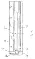
figure 2 shows a indication rod according to the present invention; -
figures 3a-3b show the indication rod shown infigure 2 in different views; -
figure 4a show parts of the load carrier bar without the indication rod and the load carrier foot fromfigures 1 a and 1 b; -
figure 4b shows parts of the load carrier bar fromfigure 1 a and 1b with the indication rod and before assembly with the load carrier foot and; -
figure 5 shows the cross section of the load carrier bar fromfigure 1 a and 1 b. -
Figures 1a-1b show parts of a roof rack 10 for a vehicle 11 with a roof 12. In this case, the vehicle is a car. The roof rack 10 comprises aload carrier bar 13 and a first load carrier foot 14 mounted in the proximity of thefirst end 15 of theload carrier bar 13 on a rail 16 of the vehicle 11. A second load carrier foot (not shown) retains theload carrier bar 13 to a second rail (not shown) at the other side of the vehicle 11. The load carrier bar can carry different types of loads such as sports equipment e.g. bicycles, kayaks, skies or the like, travel equipment such as bags, suit cases or the like, or other vehicle accessories such as roof cargo boxes, bicycle racks or the like. - For directional purposes; the
load carrier bar 13 has a longitudinal extension L and extends across the roof 12 of the vehicle 11 in the transverse direction of the vehicle 11, visualized by the Y axis infigures 1a-1b . The height of the vehicle 11, theload carrier bar 13, and the load carrier foot 14 is illustrated by the X axis, while the longitudinal direction of the vehicle 11 is illustrated by the Z axis infigures 1a-1b. Figure 1 a shows the roof rack 10 with a view towards the back side of theload carrier bar 13 whilefigure 1b shows the underside of theload carrier bar 13. The X, Y and Z axis are arranged perpendicular to each other. - The position of the first load carrier foot 14 can be adjusted, as indicated by the arrow A, in the longitudinal direction L of the
load carrier bar 13, and parallel with the Y axis infigure 1a-1b , between different positions. Dependent on the distance between the rails of the vehicle 11, or more generally between two attachment points for the first and the second load carrier foot, the position of at least the first load carrier foot 14 can be adjusted along the longitudinal extension of theload carrier bar 13 to enable the roof rack 10 to be mounted on a variety of vehicles of different sizes. The second load carrier foot can also be adjusted if necessary although for the purpose of the present invention, the position of the first and/or the second load carrier foot can be adjustable. - The roof rack 10 comprises an
indication device 30 in the form of anindication rod 31. Theindication rod 31 is displaceably arranged on the roof rack 10, and in the shown embodiment to theload carrier bar 13, enabling the determination of a wide variety of different positions of the load carrier foot 14 with respect to a reference point, as will be described in greater detail herein. -
Figure 2 shows an embodiment of anindication rod 31. Theindication rod 31 has a longitudinal extension with a T-shaped cross section, also shown infigure 3a andfigure 5 . Anupper section 32 is substantially perpendicular arranged to asupport section 33. As is noticed, theupper section 32 comprises a ruler, or at least a plurality of reference points. Infigure 2 these reference points are visualized by a metric ruler as shown in the enlarged portion offigure 2 . - As seen in
figures 2-3b , theindication rod 31 comprises a first and asecond end first end 34 of theindication rod 31 is adapted to enable theindication rod 31 to be inserted in an easy and simple manner into theload carrying bar 13. Thefirst end 34 has in the shown embodiment an angled surface to simplify insertion. At thesecond end 35 of the indication rod 31 astop surface 36 is arranged. Thestop surface 36 is in the form of a protrudingflange 37. Thestop surface 36 is adapted to cooperate with a surface of theload carrying bar 13 to prevent theindication rod 31 from entering theload carrying bar 13 too far while at the same time providing a grip surface for a user to displace theindication rod 31. -
Figure 3a shows theindication rod 31 as seen towards thefirst end 34 of theindication rod 31. Visible infigure 3a is also theupper section 32, thesupport section 33 and thestop surface 36 provided by theflange 37. As is further noticed, theupper section 32 and thesupport section 33 have substantially flat plate like forms.Figure 3b shows theindication rod 31 as seen towards one of the longitudinal sides of theindication rod 31. Visible infigure 3a is also, theupper section 32, thesupport section 33 and thestop surface 36 provided by theflange 37 extending out from the surface of theupper section 32. -
Figures 4a-4b show parts of theload carrier bar 13 and more specifically thefirst end 15 of theload carrier bar 13 with a view towards an underside 20 of theload carrier bar 13. The underside 20 is intended to face the roof 12 of the vehicle 11 after being mounted to therails 15 of the vehicle 11. - The
load carrier bar 13 is manufactured from extruded aluminum with a substantially wing like cross section, as shown infigure 5 , however it can be manufactured from other materials such as steel, cast iron, carbon reinforced fiber material, plastics or the like, and with another cross section such as an oval cross section, a rectangular cross section, or the like. As is illustrated infigure 5 , theload carrier bar 13 has an underside 20, anupper side 21, aforward side 22 and abackward side 23. Theload carrier bar 13 also has an interior 24, defined by the peripheral wall, i.e. the lower, upper, forward and backward sides 20, 21, 22, 23, of theload carrier bar 13. The interior 24 is separated intodifferent chambers 24a, 24b, 24c which imparts rigidity to theload carrier bar 13. - With reference to
figures 4a-4b , theload carrier bar 13 comprises a void for receiving an attachment member of the load carrier foot 14 to attach the load carrier foot 14 to theload carrier bar 13 and adapted to receive theindication rod 31 to enable the positioning of the load carrier foot 14 at a predetermined position. The void can be defined by parts of theload carrier bar 13 or by any other part attached thereto. The void is preferably defined by theload carrier bar 13 and more preferably by the interior 24, or parts of the interior 24a, 24b, 24c, and parts of the side walls of theload carrier bar 13. The void can be an aperture, opening or cavity adapted to receive theindication rod 31 to enable the positioning of the load carrier foot 14 at a predetermined position. - The
indication rod 31 enables a user to position the load carrier foot 14 by using theindication rod 31 as will be described in greater detail below. - In the shown embodiment, the void is a
slot 40 which extends from thefirst end 15 of theload carrier bar 13 in the longitudinal direction of theload carrier bar 13. Theslot 40 is adapted to display theindication rod 31 as is illustrated infigure 4b , after theindication rod 31 has been inserted into theload carrier bar 13 whereafter thefirst end 15 of theload carrier bar 13 is sealed by anend plug 60 attached at thefirst end 15 of theload carrier bar 13. Theslot 40 is in the shown embodiment open ended, i.e. it is not fully delimited by the wall of the lower side 20 of theload carrier bar 13, and hence theend plug 60 also seals, or in other terms delimits, theslot 40 after assembly with theload carrier bar 13. A cut out 41 in the lower side 20 at theslot 40, in the proximity of thefirst end 15 of theload carrier bar 13, provides for alock arrangement 42 together with aflange member 61 of theend plug 60. - The
slot 40 has afirst end 42. Thefirst end 42 of theslot 40 is open ended as mentioned above, but after assembly with theend plug 60 sealed and defined by theflange member 61 of theend plug 60. Asecond end 43 of theslot 40 delimits the longitudinal extension of theslot 40 in a direction towards the second end (not shown) of theload carrier bar 13. - The
slot 40 is further delimited by a first and a secondlongitudinal side edge slot 40. Instead of theslot 40 an aperture can be used. In such an embodiment, the aperture is fully delimited by the wall of the lower side 20 of theload carrier bar 13. -
Figure 4b shows theindication rod 31, after insertion into the interior 24 of theload carrier bar 13 and after theend plug 60 has been mounted to theload carrier bar 13. Theflange 37 extends into theslot 40, between the first and the second longitudinal side edges 44, 45 and also prevents theindication rod 31 from being displaced from theslot 40. After insertion, theindication rod 31 can be displaced in the longitudinal direction of theload carrier bar 13 between different positions. Each position can be preset, or pre determined by the reference points on theupper section 32 of theindication rod 31. Theindication rod 31 thus enables a user to position the load carrier foot 14 by using theindication device 30 as a position indicator directly or indirectly. It can be used directly if theindication rod 31 is used to direct indicate the desired position of the load carrier foot 14 or indirectly if it is used to position a second member which in turn is used to directly or indirectly indicate the desired position of the load carrier foot 14. After theindication rod 31, as shown infigure 4b , has been positioned, the load carrier foot 14 can be fixed to theload carrier bar 13 at the indicated position defined by theindication device 30 or theindication rod 31. - The
support section 33 of theindication rod 31 is positioned adjacent asupport surface 50 of theload carrier bar 13 as can be seen infigure 5 . Thesupport surface 50 of theload carrier bar 13 assists thesupport section 33 of theindication rod 31 to retain theupper section 32 of theindication rod 31 towards aninterior surface 20a of the lower side 20 of theload carrier bar 13 and thus be properly displayed in theslot 40. Theinterior surface 20a of the lower side 20 of theload carrier bar 13 also comprises a first and a second flange 51, 52 which extends in the longitudinal direction of theload carrier bar 13, parallel with theslot 40 of theload carrier bar 13. Theindication rod 31 is guided by the first and the second flange 51, 52 of theinterior surface 20a of the lower side 20 of theload carrier bar 13 and retained in place with respect to the transverse direction, i.e. the Z axis, as illustrated infigure 1b , while being permitted to be displaced in the longitudinal direction L of theload carrier bar 13. As an alternatively to a first and a second flange 51, 52, which extend in the longitudinal direction L of theload carrier bar 13, a plurality of separate flange members, protruding members, or a recess in the wall, can be arranged on theinterior surface 20a of the lower side 20 of theload carrier bar 13. - The
indication rod 31 can have a wide variety of forms. For example, the cross section of theindication rod 31 can be circular, square formed, triangular, or any other polygonal form, other forms are also possible. Other displaceable indication devices are also possible, it is however important that the indication device is adapted to enable repeatable readings at different positions. This enables the indication device to be operable for adapting the distance between a first and a second load carrier foot for different vehicles.
Claims (13)
- A root rack (10) for a vehicle (11), said roof rack () comprising
a load carrier bar (13) having a longitudinal direction (L),
a first and a second load carrier foot (14), wherein at least said first load carrier foot (14) is displaceable with respect to said load carrier bar (13) in said longitudinal direction (L) of said load carrier bar (13) to enable said roof rack (10) to be attachable to vehicles (12) of different sizes,
characterized in that the roof rack comprises
a readable indication rod (31) assembled with the load carrier bar for enabling the determination of different appropriate positions of said load carrying foot (14) with respect to said longitudinal direction (L) of said load carrier bar (13),
said indication rod (31) being arranged to said load carrier bar (13) and displaceable along said longitudinal direction (L) of said load carrier bar (13) between different positions with respect to said load carrier bar (13), said indication rod (31) being adapted to be read with respect to a reference point on said roof rack (10), enabling repeatable readings at different positions. - The roof rack according to claim 1, wherein said reference point is arranged on, or defined by, said load carrier bar (13).
- The roof rack according to any of the preceding claims, wherein said indication device (30) is arranged partly inside of said load carrier bar (13).
- The roof rack according to any of the preceding claims, wherein said load carrier bar (13) comprises a slot (40) and in that said indication device (30) is adapted to be displaceable in, or in the proximity of said slot (40).
- The roof rack according to claim 4, wherein said slot (40) of said load carrier bar (13) is an open ended slot (40) arranged at one end (15) of said load carrier bar (13).
- The roof rack according to claim 4 or 5, wherein said indication device (30) and said load carrier foot (14) are both displaceably arranged in said slot (40).
- The roof rack according to any of the preceding claims, wherein said indication device (30) is displaceable with respect to said first load carrying foot (14) and said load carrier bar (13).
- The roof rack according to claim 7, wherein said indication rod (31) comprises an upper section (32) adapted to be displayed in a slot (40) of said load carrier bar (13), and a support section (33) adapted to be positioned against a support surface (50) of said load carrier bar (13).
- The roof rack according to claim 7 or 8, wherein said load carrier bar (13) comprises guiding members to retain said indication rod (31) from displacement in the transverse direction of the load carrier bar (13) while permitting displacement in said longitudinal direction (L) of said load carrier bar (13).
- The roof rack according to claim 9. wherein said guiding members are formed by a first and a second flange (51, 52), a plurality of protrusions or a recess.
- A method for assembling a roof rack (10), characterized in that said method comprises the steps of;- providing a load carrier bar (13);- arranging an indication rod (31) to said load carrier bar (13) so that said indication rod (31) after assembly with said load carrier bar (10) can be displaceable in the longitudinal direction of the load carrier bar (13) between different positions,
wherein said different positions can be used to indicate an appropriate position for a load carrier foot (14);- providing a load carrier foot (14) attachable at said indicated position. - The method according to claim 11, wherein said method further comprises the step of fixing said load carrier foot (14) at said indicated position.
- The method according to claim 11 or 12, wherein said roof rack (10) is a roof rack (10) according to any of the claims 1-10.
Priority Applications (8)
| Application Number | Priority Date | Filing Date | Title |
|---|---|---|---|
| PL11156025T PL2492149T3 (en) | 2011-02-25 | 2011-02-25 | Roof rack with an indication device for a load carrier foot. |
| EP11156025.6A EP2492149B1 (en) | 2011-02-25 | 2011-02-25 | Roof rack with an indication device for a load carrier foot. |
| PCT/EP2012/053195 WO2012113925A1 (en) | 2011-02-25 | 2012-02-24 | Roof rack with an indication device for a load carrier foot |
| AU2012219425A AU2012219425B2 (en) | 2011-02-25 | 2012-02-24 | Roof rack with an indication device for a load carrier foot |
| US13/978,468 US8998046B2 (en) | 2011-02-25 | 2012-02-24 | Roof rack with an indication device for a load carrier foot |
| RU2013143286/11U RU139453U1 (en) | 2011-02-25 | 2012-02-24 | ROOF ROOF RACK WITH INDICATOR FOR RACK OF CARGO BRACKET |
| CA2825604A CA2825604C (en) | 2011-02-25 | 2012-02-24 | Roof rack with an indication device for a load carrier foot |
| CN201280007546.9A CN103338975B (en) | 2011-02-25 | 2012-02-24 | There is the roof-rack of the instruction device for goods carrying apparatus base |
Applications Claiming Priority (1)
| Application Number | Priority Date | Filing Date | Title |
|---|---|---|---|
| EP11156025.6A EP2492149B1 (en) | 2011-02-25 | 2011-02-25 | Roof rack with an indication device for a load carrier foot. |
Publications (2)
| Publication Number | Publication Date |
|---|---|
| EP2492149A1 EP2492149A1 (en) | 2012-08-29 |
| EP2492149B1 true EP2492149B1 (en) | 2013-08-07 |
Family
ID=44310823
Family Applications (1)
| Application Number | Title | Priority Date | Filing Date |
|---|---|---|---|
| EP11156025.6A Active EP2492149B1 (en) | 2011-02-25 | 2011-02-25 | Roof rack with an indication device for a load carrier foot. |
Country Status (8)
| Country | Link |
|---|---|
| US (1) | US8998046B2 (en) |
| EP (1) | EP2492149B1 (en) |
| CN (1) | CN103338975B (en) |
| AU (1) | AU2012219425B2 (en) |
| CA (1) | CA2825604C (en) |
| PL (1) | PL2492149T3 (en) |
| RU (1) | RU139453U1 (en) |
| WO (1) | WO2012113925A1 (en) |
Families Citing this family (7)
| Publication number | Priority date | Publication date | Assignee | Title |
|---|---|---|---|---|
| PL2492149T3 (en) | 2011-02-25 | 2014-01-31 | Thule Sweden Ab | Roof rack with an indication device for a load carrier foot. |
| JP6199669B2 (en) * | 2013-09-17 | 2017-09-20 | 株式会社カーメイト | Carrier bar and carrier bar assembly mechanism |
| US10040403B2 (en) * | 2015-06-09 | 2018-08-07 | Yakima Products, Inc. | Crossbar clamp actuator |
| EP3594065B1 (en) * | 2018-07-13 | 2020-11-04 | Thule Sweden AB | Load carrier |
| DE102019200661A1 (en) | 2018-08-30 | 2020-03-05 | Deckel Maho Pfronten Gmbh | MACHINE TOOL FOR MACHINING A WORKPIECE |
| US12534147B2 (en) * | 2023-06-19 | 2026-01-27 | Chad M. Buchanan | Vehicle accessory mounting system |
| USD1046753S1 (en) * | 2024-05-08 | 2024-10-15 | Zhijun He | Vehicle cross bar |
Family Cites Families (13)
| Publication number | Priority date | Publication date | Assignee | Title |
|---|---|---|---|---|
| DK151986C (en) * | 1980-04-16 | 1988-07-04 | Hans Brok | SUMMARY SCALE, LIKE A TIMBER |
| AU574669B2 (en) * | 1983-03-29 | 1988-07-14 | Unistrut Australia Pty Limited | Vehicle roof rack |
| IT1279544B1 (en) * | 1995-02-17 | 1997-12-16 | Mauro Zona | LUGGAGE RACK FOR MOTOR VEHICLES. |
| US5845828A (en) * | 1996-01-12 | 1998-12-08 | Yakima Products | Tower assembly for mounting a crossbar to a vehicle roof rack |
| US5829654A (en) * | 1996-12-31 | 1998-11-03 | Knaack Manufacturing Company | Cargo rack for vehicles |
| CA2218007A1 (en) * | 1997-10-10 | 1999-04-10 | Sportrack International Inc. | Adjustable load-carrying rack for vehicles |
| US5984155A (en) * | 1997-12-29 | 1999-11-16 | Sportrack Llc | Utility bar assemblies for a roof rack |
| EP1077160B1 (en) * | 1999-07-16 | 2001-05-02 | Fabio Pedrini | Carrier for a motor-vehicle roof |
| US6905053B2 (en) * | 2003-01-10 | 2005-06-14 | Watermark Paddlesports, Inc. | Rack tower |
| AU2009262302A1 (en) * | 2008-06-23 | 2009-12-30 | Yakima Products, Inc. | Rack tower for securing crossbars on top of a vehicle |
| CN201390205Y (en) * | 2009-02-25 | 2010-01-27 | 宁波纽特汽车配件有限公司 | Car roof shelf |
| CN101559738B (en) * | 2009-03-12 | 2011-09-28 | 宁波纽特汽车配件有限公司 | Vehicle roof frame |
| PL2492149T3 (en) | 2011-02-25 | 2014-01-31 | Thule Sweden Ab | Roof rack with an indication device for a load carrier foot. |
-
2011
- 2011-02-25 PL PL11156025T patent/PL2492149T3/en unknown
- 2011-02-25 EP EP11156025.6A patent/EP2492149B1/en active Active
-
2012
- 2012-02-24 US US13/978,468 patent/US8998046B2/en active Active
- 2012-02-24 CA CA2825604A patent/CA2825604C/en active Active
- 2012-02-24 RU RU2013143286/11U patent/RU139453U1/en active
- 2012-02-24 WO PCT/EP2012/053195 patent/WO2012113925A1/en not_active Ceased
- 2012-02-24 CN CN201280007546.9A patent/CN103338975B/en active Active
- 2012-02-24 AU AU2012219425A patent/AU2012219425B2/en not_active Ceased
Also Published As
| Publication number | Publication date |
|---|---|
| AU2012219425B2 (en) | 2015-09-17 |
| CA2825604A1 (en) | 2012-08-30 |
| AU2012219425A1 (en) | 2013-06-27 |
| US20140144957A1 (en) | 2014-05-29 |
| CA2825604C (en) | 2018-04-03 |
| EP2492149A1 (en) | 2012-08-29 |
| CN103338975A (en) | 2013-10-02 |
| WO2012113925A1 (en) | 2012-08-30 |
| PL2492149T3 (en) | 2014-01-31 |
| US8998046B2 (en) | 2015-04-07 |
| CN103338975B (en) | 2016-08-17 |
| RU139453U1 (en) | 2014-04-20 |
Similar Documents
| Publication | Publication Date | Title |
|---|---|---|
| AU2012219425B2 (en) | Roof rack with an indication device for a load carrier foot | |
| CN107415843B (en) | Bearing strip | |
| US7958963B2 (en) | Assembly support for a motor vehicle transmission | |
| KR20140051414A (en) | A load carrier foot and a load carrying roof rack for a vehicle comprising a load carrier foot | |
| US20090243331A1 (en) | Tonneau cover cargo containment track rail system | |
| US8303027B2 (en) | Front window formed in cabin of construction machine | |
| US4372469A (en) | Article carrier having variably positionable cross-rail bracket | |
| US20150063938A1 (en) | Partition Assembly for a Vehicular Cargo Area | |
| US10875585B2 (en) | Cap assemblies for truck bed sidewalls including adaptor assemblies with accessory channels | |
| US20090025957A1 (en) | Extruded wire duct end cap | |
| US9970760B2 (en) | Removable end cap assembly for a level | |
| US20160280143A1 (en) | Carrier bar and carrier bar assembly structure | |
| US10442370B2 (en) | Truck deck rail tool storage and truck deck and truck having the same | |
| US6131981A (en) | Shelves for vehicular utility bodies | |
| CN107009949B (en) | Anchor plate for cargo box of pickup truck | |
| US20190100128A1 (en) | Truck bed rear cargo tie down engagement structure | |
| BR112020001477A2 (en) | method and system for securing heavy loads | |
| EP2011693B1 (en) | Roof rail, mounting component and vehicle | |
| AU2005211598A1 (en) | Caps for Use in Securing Palletised ETC Loads | |
| US11180092B2 (en) | Vehicle bedliner | |
| NZ716416A (en) | A support structure | |
| FI89572B (en) | Haollare Foer varningstriangel Foer personbil | |
| ITRM20070155A1 (en) | DEVICE FOR THE TRANSPORT OF VEHICLES WITH TWO WHEELS, IN PARTICULAR BICYCLES |
Legal Events
| Date | Code | Title | Description |
|---|---|---|---|
| PUAI | Public reference made under article 153(3) epc to a published international application that has entered the european phase |
Free format text: ORIGINAL CODE: 0009012 |
|
| AK | Designated contracting states |
Kind code of ref document: A1 Designated state(s): AL AT BE BG CH CY CZ DE DK EE ES FI FR GB GR HR HU IE IS IT LI LT LU LV MC MK MT NL NO PL PT RO RS SE SI SK SM TR |
|
| AX | Request for extension of the european patent |
Extension state: BA ME |
|
| 17P | Request for examination filed |
Effective date: 20120925 |
|
| GRAP | Despatch of communication of intention to grant a patent |
Free format text: ORIGINAL CODE: EPIDOSNIGR1 |
|
| INTG | Intention to grant announced |
Effective date: 20130404 |
|
| GRAS | Grant fee paid |
Free format text: ORIGINAL CODE: EPIDOSNIGR3 |
|
| GRAA | (expected) grant |
Free format text: ORIGINAL CODE: 0009210 |
|
| AK | Designated contracting states |
Kind code of ref document: B1 Designated state(s): AL AT BE BG CH CY CZ DE DK EE ES FI FR GB GR HR HU IE IS IT LI LT LU LV MC MK MT NL NO PL PT RO RS SE SI SK SM TR |
|
| REG | Reference to a national code |
Ref country code: GB Ref legal event code: FG4D |
|
| REG | Reference to a national code |
Ref country code: CH Ref legal event code: EP Ref country code: AT Ref legal event code: REF Ref document number: 625606 Country of ref document: AT Kind code of ref document: T Effective date: 20130815 |
|
| REG | Reference to a national code |
Ref country code: IE Ref legal event code: FG4D |
|
| REG | Reference to a national code |
Ref country code: DE Ref legal event code: R096 Ref document number: 602011002569 Country of ref document: DE Effective date: 20131002 |
|
| REG | Reference to a national code |
Ref country code: SE Ref legal event code: TRGR |
|
| REG | Reference to a national code |
Ref country code: AT Ref legal event code: MK05 Ref document number: 625606 Country of ref document: AT Kind code of ref document: T Effective date: 20130807 |
|
| REG | Reference to a national code |
Ref country code: NL Ref legal event code: VDEP Effective date: 20130807 |
|
| REG | Reference to a national code |
Ref country code: LT Ref legal event code: MG4D |
|
| PG25 | Lapsed in a contracting state [announced via postgrant information from national office to epo] |
Ref country code: AT Free format text: LAPSE BECAUSE OF FAILURE TO SUBMIT A TRANSLATION OF THE DESCRIPTION OR TO PAY THE FEE WITHIN THE PRESCRIBED TIME-LIMIT Effective date: 20130807 Ref country code: HR Free format text: LAPSE BECAUSE OF FAILURE TO SUBMIT A TRANSLATION OF THE DESCRIPTION OR TO PAY THE FEE WITHIN THE PRESCRIBED TIME-LIMIT Effective date: 20130807 Ref country code: PT Free format text: LAPSE BECAUSE OF FAILURE TO SUBMIT A TRANSLATION OF THE DESCRIPTION OR TO PAY THE FEE WITHIN THE PRESCRIBED TIME-LIMIT Effective date: 20131209 Ref country code: LT Free format text: LAPSE BECAUSE OF FAILURE TO SUBMIT A TRANSLATION OF THE DESCRIPTION OR TO PAY THE FEE WITHIN THE PRESCRIBED TIME-LIMIT Effective date: 20130807 Ref country code: CY Free format text: LAPSE BECAUSE OF FAILURE TO SUBMIT A TRANSLATION OF THE DESCRIPTION OR TO PAY THE FEE WITHIN THE PRESCRIBED TIME-LIMIT Effective date: 20130911 Ref country code: IS Free format text: LAPSE BECAUSE OF FAILURE TO SUBMIT A TRANSLATION OF THE DESCRIPTION OR TO PAY THE FEE WITHIN THE PRESCRIBED TIME-LIMIT Effective date: 20131207 Ref country code: NO Free format text: LAPSE BECAUSE OF FAILURE TO SUBMIT A TRANSLATION OF THE DESCRIPTION OR TO PAY THE FEE WITHIN THE PRESCRIBED TIME-LIMIT Effective date: 20131107 |
|
| REG | Reference to a national code |
Ref country code: PL Ref legal event code: T3 |
|
| PG25 | Lapsed in a contracting state [announced via postgrant information from national office to epo] |
Ref country code: NL Free format text: LAPSE BECAUSE OF FAILURE TO SUBMIT A TRANSLATION OF THE DESCRIPTION OR TO PAY THE FEE WITHIN THE PRESCRIBED TIME-LIMIT Effective date: 20130807 Ref country code: GR Free format text: LAPSE BECAUSE OF FAILURE TO SUBMIT A TRANSLATION OF THE DESCRIPTION OR TO PAY THE FEE WITHIN THE PRESCRIBED TIME-LIMIT Effective date: 20131108 Ref country code: FI Free format text: LAPSE BECAUSE OF FAILURE TO SUBMIT A TRANSLATION OF THE DESCRIPTION OR TO PAY THE FEE WITHIN THE PRESCRIBED TIME-LIMIT Effective date: 20130807 Ref country code: LV Free format text: LAPSE BECAUSE OF FAILURE TO SUBMIT A TRANSLATION OF THE DESCRIPTION OR TO PAY THE FEE WITHIN THE PRESCRIBED TIME-LIMIT Effective date: 20130807 Ref country code: SI Free format text: LAPSE BECAUSE OF FAILURE TO SUBMIT A TRANSLATION OF THE DESCRIPTION OR TO PAY THE FEE WITHIN THE PRESCRIBED TIME-LIMIT Effective date: 20130807 Ref country code: BE Free format text: LAPSE BECAUSE OF FAILURE TO SUBMIT A TRANSLATION OF THE DESCRIPTION OR TO PAY THE FEE WITHIN THE PRESCRIBED TIME-LIMIT Effective date: 20130807 |
|
| PG25 | Lapsed in a contracting state [announced via postgrant information from national office to epo] |
Ref country code: CY Free format text: LAPSE BECAUSE OF FAILURE TO SUBMIT A TRANSLATION OF THE DESCRIPTION OR TO PAY THE FEE WITHIN THE PRESCRIBED TIME-LIMIT Effective date: 20130807 |
|
| PG25 | Lapsed in a contracting state [announced via postgrant information from national office to epo] |
Ref country code: SK Free format text: LAPSE BECAUSE OF FAILURE TO SUBMIT A TRANSLATION OF THE DESCRIPTION OR TO PAY THE FEE WITHIN THE PRESCRIBED TIME-LIMIT Effective date: 20130807 Ref country code: RO Free format text: LAPSE BECAUSE OF FAILURE TO SUBMIT A TRANSLATION OF THE DESCRIPTION OR TO PAY THE FEE WITHIN THE PRESCRIBED TIME-LIMIT Effective date: 20130807 Ref country code: CZ Free format text: LAPSE BECAUSE OF FAILURE TO SUBMIT A TRANSLATION OF THE DESCRIPTION OR TO PAY THE FEE WITHIN THE PRESCRIBED TIME-LIMIT Effective date: 20130807 Ref country code: EE Free format text: LAPSE BECAUSE OF FAILURE TO SUBMIT A TRANSLATION OF THE DESCRIPTION OR TO PAY THE FEE WITHIN THE PRESCRIBED TIME-LIMIT Effective date: 20130807 Ref country code: DK Free format text: LAPSE BECAUSE OF FAILURE TO SUBMIT A TRANSLATION OF THE DESCRIPTION OR TO PAY THE FEE WITHIN THE PRESCRIBED TIME-LIMIT Effective date: 20130807 |
|
| PG25 | Lapsed in a contracting state [announced via postgrant information from national office to epo] |
Ref country code: ES Free format text: LAPSE BECAUSE OF FAILURE TO SUBMIT A TRANSLATION OF THE DESCRIPTION OR TO PAY THE FEE WITHIN THE PRESCRIBED TIME-LIMIT Effective date: 20130807 Ref country code: IT Free format text: LAPSE BECAUSE OF FAILURE TO SUBMIT A TRANSLATION OF THE DESCRIPTION OR TO PAY THE FEE WITHIN THE PRESCRIBED TIME-LIMIT Effective date: 20130807 |
|
| PLBE | No opposition filed within time limit |
Free format text: ORIGINAL CODE: 0009261 |
|
| STAA | Information on the status of an ep patent application or granted ep patent |
Free format text: STATUS: NO OPPOSITION FILED WITHIN TIME LIMIT |
|
| 26N | No opposition filed |
Effective date: 20140508 |
|
| REG | Reference to a national code |
Ref country code: DE Ref legal event code: R097 Ref document number: 602011002569 Country of ref document: DE Effective date: 20140508 |
|
| PG25 | Lapsed in a contracting state [announced via postgrant information from national office to epo] |
Ref country code: MC Free format text: LAPSE BECAUSE OF FAILURE TO SUBMIT A TRANSLATION OF THE DESCRIPTION OR TO PAY THE FEE WITHIN THE PRESCRIBED TIME-LIMIT Effective date: 20130807 Ref country code: LU Free format text: LAPSE BECAUSE OF FAILURE TO SUBMIT A TRANSLATION OF THE DESCRIPTION OR TO PAY THE FEE WITHIN THE PRESCRIBED TIME-LIMIT Effective date: 20140225 |
|
| REG | Reference to a national code |
Ref country code: CH Ref legal event code: PL |
|
| PG25 | Lapsed in a contracting state [announced via postgrant information from national office to epo] |
Ref country code: LI Free format text: LAPSE BECAUSE OF NON-PAYMENT OF DUE FEES Effective date: 20140228 Ref country code: CH Free format text: LAPSE BECAUSE OF NON-PAYMENT OF DUE FEES Effective date: 20140228 |
|
| REG | Reference to a national code |
Ref country code: IE Ref legal event code: MM4A |
|
| PG25 | Lapsed in a contracting state [announced via postgrant information from national office to epo] |
Ref country code: IE Free format text: LAPSE BECAUSE OF NON-PAYMENT OF DUE FEES Effective date: 20140225 |
|
| REG | Reference to a national code |
Ref country code: FR Ref legal event code: PLFP Year of fee payment: 6 |
|
| PG25 | Lapsed in a contracting state [announced via postgrant information from national office to epo] |
Ref country code: MT Free format text: LAPSE BECAUSE OF FAILURE TO SUBMIT A TRANSLATION OF THE DESCRIPTION OR TO PAY THE FEE WITHIN THE PRESCRIBED TIME-LIMIT Effective date: 20130807 |
|
| PG25 | Lapsed in a contracting state [announced via postgrant information from national office to epo] |
Ref country code: SM Free format text: LAPSE BECAUSE OF FAILURE TO SUBMIT A TRANSLATION OF THE DESCRIPTION OR TO PAY THE FEE WITHIN THE PRESCRIBED TIME-LIMIT Effective date: 20130807 |
|
| PG25 | Lapsed in a contracting state [announced via postgrant information from national office to epo] |
Ref country code: BG Free format text: LAPSE BECAUSE OF FAILURE TO SUBMIT A TRANSLATION OF THE DESCRIPTION OR TO PAY THE FEE WITHIN THE PRESCRIBED TIME-LIMIT Effective date: 20130807 Ref country code: RS Free format text: LAPSE BECAUSE OF FAILURE TO SUBMIT A TRANSLATION OF THE DESCRIPTION OR TO PAY THE FEE WITHIN THE PRESCRIBED TIME-LIMIT Effective date: 20130807 |
|
| PG25 | Lapsed in a contracting state [announced via postgrant information from national office to epo] |
Ref country code: HU Free format text: LAPSE BECAUSE OF FAILURE TO SUBMIT A TRANSLATION OF THE DESCRIPTION OR TO PAY THE FEE WITHIN THE PRESCRIBED TIME-LIMIT; INVALID AB INITIO Effective date: 20110225 Ref country code: TR Free format text: LAPSE BECAUSE OF FAILURE TO SUBMIT A TRANSLATION OF THE DESCRIPTION OR TO PAY THE FEE WITHIN THE PRESCRIBED TIME-LIMIT Effective date: 20130807 |
|
| REG | Reference to a national code |
Ref country code: FR Ref legal event code: PLFP Year of fee payment: 7 |
|
| REG | Reference to a national code |
Ref country code: FR Ref legal event code: PLFP Year of fee payment: 8 |
|
| PG25 | Lapsed in a contracting state [announced via postgrant information from national office to epo] |
Ref country code: MK Free format text: LAPSE BECAUSE OF FAILURE TO SUBMIT A TRANSLATION OF THE DESCRIPTION OR TO PAY THE FEE WITHIN THE PRESCRIBED TIME-LIMIT Effective date: 20130807 |
|
| PG25 | Lapsed in a contracting state [announced via postgrant information from national office to epo] |
Ref country code: AL Free format text: LAPSE BECAUSE OF FAILURE TO SUBMIT A TRANSLATION OF THE DESCRIPTION OR TO PAY THE FEE WITHIN THE PRESCRIBED TIME-LIMIT Effective date: 20130807 |
|
| PGFP | Annual fee paid to national office [announced via postgrant information from national office to epo] |
Ref country code: SE Payment date: 20210219 Year of fee payment: 11 |
|
| PGFP | Annual fee paid to national office [announced via postgrant information from national office to epo] |
Ref country code: GB Payment date: 20220222 Year of fee payment: 12 |
|
| REG | Reference to a national code |
Ref country code: SE Ref legal event code: EUG |
|
| PG25 | Lapsed in a contracting state [announced via postgrant information from national office to epo] |
Ref country code: SE Free format text: LAPSE BECAUSE OF NON-PAYMENT OF DUE FEES Effective date: 20220226 |
|
| P01 | Opt-out of the competence of the unified patent court (upc) registered |
Effective date: 20230528 |
|
| GBPC | Gb: european patent ceased through non-payment of renewal fee |
Effective date: 20230225 |
|
| PG25 | Lapsed in a contracting state [announced via postgrant information from national office to epo] |
Ref country code: GB Free format text: LAPSE BECAUSE OF NON-PAYMENT OF DUE FEES Effective date: 20230225 |
|
| PG25 | Lapsed in a contracting state [announced via postgrant information from national office to epo] |
Ref country code: GB Free format text: LAPSE BECAUSE OF NON-PAYMENT OF DUE FEES Effective date: 20230225 |
|
| PGFP | Annual fee paid to national office [announced via postgrant information from national office to epo] |
Ref country code: DE Payment date: 20260220 Year of fee payment: 16 |
|
| PGFP | Annual fee paid to national office [announced via postgrant information from national office to epo] |
Ref country code: FR Payment date: 20260224 Year of fee payment: 16 |
|
| PGFP | Annual fee paid to national office [announced via postgrant information from national office to epo] |
Ref country code: PL Payment date: 20260212 Year of fee payment: 16 |