CN101559738B - Vehicle roof frame - Google Patents
Vehicle roof frame Download PDFInfo
- Publication number
- CN101559738B CN101559738B CN2009103008023A CN200910300802A CN101559738B CN 101559738 B CN101559738 B CN 101559738B CN 2009103008023 A CN2009103008023 A CN 2009103008023A CN 200910300802 A CN200910300802 A CN 200910300802A CN 101559738 B CN101559738 B CN 101559738B
- Authority
- CN
- China
- Prior art keywords
- groove
- insert
- support body
- runners
- frame
- Prior art date
- Legal status (The legal status is an assumption and is not a legal conclusion. Google has not performed a legal analysis and makes no representation as to the accuracy of the status listed.)
- Expired - Fee Related
Links
Images


Abstract
The invention relates to a vehicle roof frame. The invention solves the problem that the vehicle roof frame can not be adjusted in the prior art and provides a vehicle roof frame which has simple operation and can adjust the distance between two bases freely. The technical proposal is as follows: the vehicle roof frame comprises two bases and a frame; the bases are arranged at two ends of the frame; the section of the frame is a dripping-shaped structure with thick front part and thin rear part; the shape of the section reduces the resistance when the air passes; the front end of the upper surface of the frame is provided with an anti-wind bar; the vehicle roof frame also comprises an insertion part which is arranged at two ends of the frame; the bases and the insertion parts are fixedly connected with each other; and the insertion part is provided with an adjusting control device. The vehicle roof frame can adjust the distance between two bases freely, can be convenient to be installed on the vehicle roof of different sizes, improves the utilization ratio of the vehicle roof frame, and optimizes the use of the resource to maximum extent; the frame body adopts a dripping-shaped streamline, greatly reduces the resistance generated during the driving process of the vehicle, reduces the energy consumption of the engine, improves the vehicle speed and reduces the noise.
Description
Technical field
The present invention relates to a kind of top holder.
Background technology
The car roof frame of selling on the market generally all is uncontrollable now, needs the top holder of different sizes when installing on the automobile of different sizes, and the top holder that this just needs to produce different sizes has not only brought inconvenience to installation, has wasted resource simultaneously.China's utility model patent 200720079602.6 discloses a kind of car boot rack device, it comprises mount pad, protecting cover, the luggage hack lever, the heavy hole of mount pad neck is installed in the screens that spring leaf is provided with punching out and is connected with the luggage hack lever, be provided with the pin of band dowel bushing in the protecting cover, pin by the band dowel bushing is connected with corresponding hole on the mount pad, whole device is again by screw or be weldingly fixed on the roof, but this device is unadjustable, can not different sizes automobile on install, brought inconvenience to installation, resource is not fully utilized yet simultaneously.Its shape of the support body of present many top holders is generally square, circular or semicircle strip in addition, Chinese utility model patent 200720079602.6 as mentioned above, also have Chinese utility model 95243385.0 disclosed a kind of MPV (Multi-Purpose Vehicle) upper frames in addition, the support body of their top holders is simple circle or semicircle strip.In vehicle traveling process, the support body of this shape can produce bigger air resistance, and the energy of a large amount of consumption of engine of air resistance influences the speed of a motor vehicle, and also can produce bigger noise.
Summary of the invention
The present invention solves the uncontrollable problem of existing in prior technology top holder, provides a kind of simple to operate, but free adjustment bipod distance between seats from top holder.
Another goal of the invention of the present invention is to have solved the top holder that exists in the prior art to produce air resistance in the vehicle ' process big, cause the driving engine power consumption big, influence the problem of the speed of a motor vehicle, provide a kind of rational in infrastructure, air resistance is little in the vehicle ' process, the top holder that noise is low.
Above-mentioned technical matters of the present invention is mainly solved by following technical proposals: a kind of top holder, comprise runners and support body, runners is arranged on the support body two ends, it is characterized in that: the cross section of described support body is the thin drops structure in preceding thick back, this shape has reduced the resistance that air flows through generation, be provided with brokenly the wind bar at support body upper surface front end, top holder also comprises insert, insert is installed in the support body two ends, runners and insert are fixedly linked, insert is provided with control set for adjusting, insert inserts respectively and is installed in the support body two ends, and can on support body, stretch, just can regulate distance between two runners by regulating insert, top holder can be installed on different big or small car bodies.Described control apparatus is by screw, spring, the buckle structure that attaching parts and connecting element are formed, described insert takes the shape of the letter U, be provided with groove at insert on one side, in groove, be provided with spacer groove is separated into first groove and second groove, the insert end face is provided with through hole, this through hole is connected with first groove, on the second groove both sides wall, be respectively arranged with the rotating shaft groove, described spacer upper end is lower than the insert upper surface, make first groove form an opening that links to each other in the insert upper surface with second groove, described connecting element both sides are respectively arranged with rotating shaft, connecting element top is provided with gantry column, connecting element bottom front end is provided with coupler body, this connecting element gantry column is arranged in second groove up, rotating shaft correspondence respectively is placed in the rotating shaft groove, attaching parts is L-shaped, its end positions is respectively arranged with connecting bore, this attaching parts lies in first groove and second groove in the opening that the insert upper surface forms, attaching parts one end stretches in first groove, connecting bore links to each other with gantry column on the other end, described screw is arranged in the through hole and penetrates first groove, link to each other with the attaching parts one end connecting bore in stretching into first groove, described spring is arranged in first groove, is folded between attaching parts and the spacer.Be provided with the location division on the spacer in first groove, spring one end is enclosed within on the location division, the part of other end overhead in attaching parts stretches into first groove, screw passes connecting bore and forms a bit of location division, the spring other end is nested with on screw, has formed a reset attachment like this on screw and attaching parts.The inside face of bottom, support body two ends is provided with the grid that matches with the connecting element coupler body.
A kind of preferred version as such scheme, described runners top is claw-like, its shape matches with the support body shape, insert is plugged on the support body end and is placed in the runners top, insert front end and runners fix by bolt, also are provided with a pin enclosing cover, and this pin enclosing cover buckles on runners, outside pin, cover and also be provided with lock body, pin enclosing cover and runners are fixed by lock body.
A kind of preferred version as such scheme has draw-in groove on support body, the extrusion molding bar is installed in draw-in groove.This extrusion molding bar is that softnesses such as rubber or plastics have elastomeric objects and make.
Therefore, the distance of top holder of the present invention between can free adjustment two runners can be easily installed on the roofs of different sizes, improved the Occupation coefficient of top holder, largest optimization the use of resource; Support body adopts the drops streamline contour in addition, reduces the resistance that produces in the vehicle ' greatly, has reduced the consumption of engine power, has promoted the speed of a motor vehicle, and has reduced noise.
Description of drawings
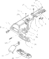
Accompanying drawing 1 is a kind of structure exploded perspective view of the present invention;
Accompanying drawing 2 is a kind of structural representations of insert of the present invention;
Accompanying drawing 3 is a kind of structural representations of connecting element of the present invention;
Accompanying drawing 4 is a kind of structural representations of support body of the present invention;
Accompanying drawing 5 is a kind of structural representations of accompanying drawing 4 local A;
Accompanying drawing 6 is a kind of B-B structure cutaway views of accompanying drawing 4.
The specific embodiment
Below by embodiment, and in conjunction with the accompanying drawings, technical scheme of the present invention is described in further detail.
Embodiment:
Top holder adjustment structure of the present invention mainly comprises runners 2, support body 25, insert 3, insert is installed in the support body two ends, be provided with control set for adjusting between insert and support body, the buckle structure that this control set for adjusting is made up of screw 4, spring 5, attaching parts 7 and connecting element 6, can regulate the distance between insert and support body one end, insert and runners fix, and runners is installed on the roof by modes such as bolt or welding.As shown in Figure 6, its cross section of described support body becomes drops, is provided with brokenly wind bar 31 on support body upper surface front end.Support body is a hollow form, on support body, also have a draw-in groove 32, this draw-in groove is with support body cavity separated into two parts, be used to insert insert, this draw-in groove opening is less than the draw-in groove inner width, also be provided with a draw-in groove 2 34 in the draw-in groove bottom, extrusion molding bar 33 is installed in draw-in groove, this extrusion molding bar is that softnesses such as rubber or plastics have the elastomeric objects making, its upper end is complementary with the draw-in groove opening shape, extrusion molding bar lower end is provided with card article portion 35, and it matches with draw-in groove two, and card article portion is arranged in the draw-in groove two the extrusion molding bar is fixed on the support body.
As shown in Figure 1, be provided with breach in the middle of the insert 3, be a U-shaped structure, the both sides shape of insert U-shaped matches (as shown in Figure 6) with the shape of support body 25 both ends opens, this insert is inserted in the support body two ends, is provided with diff-H between the bottom of insert U-shaped and the both sides, makes it to form a stop part, when insert inserted the support body two ends, insert terminated in this stop part.
On one side of insert U-shaped, be provided with groove, in groove, be provided with a spacer 18 groove is separated into first groove 19 and second groove, 17 two parts, these spacer 18 upper ends are lower than the insert upper surface, make first groove form an opening that links to each other at the insert upper surface with second groove, on the face of insert U-shaped bottom end, be provided with through hole 21, this through hole 21 1 is connected with first groove, is respectively arranged with rotating shaft groove 20 on second groove, 17 both sides walls, is used for mounting fixing parts 6.
As shown in Figure 3, these connecting element both sides are respectively arranged with rotating shaft 22, connecting element top is provided with gantry column 23, its underpart front end is provided with hook portion 24, gantry column and coupler body lay respectively at the both sides of rotating shaft 22, this connecting element gantry column is installed in second groove 19 up, and rotating shaft correspondence respectively is arranged in the rotating shaft groove 20.As shown in Figure 1, attaching parts 7 is the L shape, its two ends are respectively arranged with connecting bore 27, this attaching parts lies in the opening of insert upper surface first groove and the formation of second groove down, attaching parts one end connecting bore links to each other with gantry column 23 on the connecting element, the connecting bore other end stretches in first groove, described screw 4 inserts and penetrates first groove by through hole 21, with stretch into the first groove interconnecting piece, one end connecting bore and link to each other, spring 5 is arranged in first groove 19, be provided with location division 28 on the spacer in first groove, spring one end is enclosed within on the location division 28, the part of other end overhead in attaching parts stretches into first groove, described screw 4 passes connecting bore and forms a bit of location division, and the spring other end is nested with on screw.As shown in Figure 5, support body two ends lower surface is provided with grid 26, and when insert inserted the support body two ends, the hook portion of the connecting element of installing on the insert was just in time corresponding with grid.
When operation, press screw, screw promotes the attaching parts motion, attaching parts then drives on the connecting element gantry column motion, and the connecting element moving axis that rotates is rotated, and coupler body upwards lifts and broken away from grid, just can promote insert this moment, regulate the distance of insert and support body, after regulating, unclamp screw, because the effect of spring, attaching parts is returned to original position, and attaching parts drives connecting element and rotates, and coupler body puts down and is stuck in the grid.
Described runners 2 tops are claw-like, its shape just in time matches with insert and support body shape, insert is nested with on runners top, runners is provided with and the corresponding to mounting hole 29 of hexagonal nut shape, hexagonal nut 16 is arranged in the mounting hole, be provided with the installation through hole in insert 3 and mounting hole relevant position, bolt 15 passes to be installed through hole and penetrates in the mounting hole and be connected with hexagonal nut, and runners and insert are fixed.
This runners also comprises inner piece 36, seat cushion 9, base 10 and hook spare 11, seat cushion is installed on the base, fix by bolt, be provided with two free bearings 30 on cushion, be provided with the hinge head that matches with free bearing in the runners lower end, the hinge head links to each other by bearing pin 13 with free bearing, described hook spare one end is provided with installation portion, this installation portion becomes L shaped, its termination is provided with mounting hole, installation portion is placed on cushion, and described inner piece 36 is arranged on the installation portion, and fixes with seat cushion, on inner piece, be provided with a square nut hole, the installation portion termination extend in the square nut hole, also is provided with a square nut 14 in nut bore, by hexagonal cylinder end clamping fixed screw in one 12 installation portion is fixed on the inner piece.As shown in Figure 1, also be provided with a pin enclosing cover 1, this pin enclosing cover upper end is complementary with the opening shape of runners top claw shaped body, and this pin enclosing cover buckles on runners, covers outside pin and also is provided with lock body 8, by lock body pin enclosing cover and runners is fixed.
Specific embodiment described herein only is that spirit of the present invention is made casehistory.The technical personnel of the technical field of the invention can be made various modifications or replenishes or adopt similar mode to substitute described specific embodiment, but can't depart from spirit of the present invention or surmount the defined scope of appended claims.
Although this paper has used runners morely, the possibility of using other term do not got rid of in terms such as insert, support body, pin enclosing cover.Using these terms only is in order to describe and explain essence of the present invention more easily; They are construed to any additional restriction all is contrary with spirit of the present invention.
Claims (3)
1. top holder, comprise runners and support body, runners is arranged on the support body two ends, it is characterized in that: the cross section of described support body (25) is the thin drops structure in preceding thick back, be provided with brokenly wind bar (31) at support body upper surface front end, top holder also comprises insert (3), insert is installed in support body (25) two ends, runners (2) is fixedly linked with insert, insert (3) is provided with control set for adjusting, described control apparatus is by screw (4), spring (5), the buckle structure that attaching parts (7) and connecting element (6) are formed, described insert (3) takes the shape of the letter U, be provided with groove at insert on one side, in groove, be provided with spacer (18) groove is separated into first groove (19) and second groove (17), insert (3) end face is provided with through hole (21), this through hole is connected with first groove (19), on the wall of second groove (17) both sides, be respectively arranged with rotating shaft groove (20), described spacer (18) upper end is lower than insert (3) upper surface, make first groove (19) form an opening that links to each other in the insert upper surface with second groove (17), described connecting element (6) both sides are respectively arranged with rotating shaft (22), connecting element top is provided with gantry column (23), connecting element bottom front end is provided with coupler body (24), this connecting element gantry column (23) is arranged in second groove (17) up, rotating shaft (22) correspondence respectively is placed in the rotating shaft groove (20), attaching parts (7) is L-shaped, its end positions is respectively arranged with connecting bore (27), this attaching parts lies in first groove (19) and second groove (17) in the opening that the insert upper surface forms, attaching parts one end stretches in first groove (19), connecting bore links to each other with gantry column (23) on the other end, described screw (4) is arranged in the through hole (21) and penetrates first groove (19), link to each other with attaching parts (7) the one end connecting bores (27) in stretching into first groove, described spring (5) is arranged in first groove (19), be folded between attaching parts and the spacer (18), the inside face of support body (25) bottom, two ends is provided with the grid (26) that matches with connecting element (6) coupler body.
2. top holder according to claim 1, it is characterized in that described runners (2) top is claw-like, its shape matches with support body (25) shape, insert is plugged on the support body end and is placed in runners (2) top, insert front end and runners fix by bolt, also are provided with a pin enclosing cover (1), and this pin enclosing cover buckles on runners, outside pin, cover and also be provided with lock body (8), pin enclosing cover and runners are fixed by lock body.
3. top holder according to claim 1 is characterized in that having draw-in groove (32) on support body (25), and extrusion molding bar (33) is installed in draw-in groove.
Priority Applications (1)
| Application Number | Priority Date | Filing Date | Title |
|---|---|---|---|
| CN2009103008023A CN101559738B (en) | 2009-03-12 | 2009-03-12 | Vehicle roof frame |
Applications Claiming Priority (1)
| Application Number | Priority Date | Filing Date | Title |
|---|---|---|---|
| CN2009103008023A CN101559738B (en) | 2009-03-12 | 2009-03-12 | Vehicle roof frame |
Publications (2)
| Publication Number | Publication Date |
|---|---|
| CN101559738A CN101559738A (en) | 2009-10-21 |
| CN101559738B true CN101559738B (en) | 2011-09-28 |
Family
ID=41218767
Family Applications (1)
| Application Number | Title | Priority Date | Filing Date |
|---|---|---|---|
| CN2009103008023A Expired - Fee Related CN101559738B (en) | 2009-03-12 | 2009-03-12 | Vehicle roof frame |
Country Status (1)
| Country | Link |
|---|---|
| CN (1) | CN101559738B (en) |
Families Citing this family (9)
| Publication number | Priority date | Publication date | Assignee | Title |
|---|---|---|---|---|
| NZ561811A (en) * | 2007-09-21 | 2010-06-25 | Hubco Automotive Ltd | Extendable roof rack |
| NZ561809A (en) | 2007-09-21 | 2009-11-27 | Hubco Automotive Ltd | Resilient infill |
| NZ571287A (en) | 2008-09-15 | 2011-03-31 | Hubco Automotive Ltd | A bracket and a crossbar assembly for a roof rack |
| PL2492149T3 (en) * | 2011-02-25 | 2014-01-31 | Thule Sweden Ab | Roof rack with an indication device for a load carrier foot. |
| EP2844523B1 (en) | 2012-04-30 | 2017-04-26 | Yakima Australia Pty Limited | Retention dock |
| CA2880705A1 (en) | 2012-07-30 | 2014-02-06 | Yakima Innovation Development Corporation | Crossbar t-slot infill |
| US10040403B2 (en) | 2015-06-09 | 2018-08-07 | Yakima Products, Inc. | Crossbar clamp actuator |
| EP4140818B1 (en) * | 2018-07-02 | 2024-02-14 | Thule Sweden AB | Load carrier |
| CN109140326B (en) * | 2018-10-11 | 2024-04-02 | 中山市鼎亮照明电器有限公司 | Lamp arm mounting structure and ceiling lamp |
Citations (1)
| Publication number | Priority date | Publication date | Assignee | Title |
|---|---|---|---|---|
| FR2723046A1 (en) * | 1994-07-27 | 1996-02-02 | Peugeot Automobiles Sa | Adjustable width roof rack for vehicle |
-
2009
- 2009-03-12 CN CN2009103008023A patent/CN101559738B/en not_active Expired - Fee Related
Patent Citations (1)
| Publication number | Priority date | Publication date | Assignee | Title |
|---|---|---|---|---|
| FR2723046A1 (en) * | 1994-07-27 | 1996-02-02 | Peugeot Automobiles Sa | Adjustable width roof rack for vehicle |
Also Published As
| Publication number | Publication date |
|---|---|
| CN101559738A (en) | 2009-10-21 |
Similar Documents
| Publication | Publication Date | Title |
|---|---|---|
| CN101559738B (en) | Vehicle roof frame | |
| CN101559737B (en) | Adjusting structure of vehicle roof frame | |
| CN103481832A (en) | Assembled hanging bracket type air flue baggage holder for passenger car | |
| CN201249704Y (en) | Theftproof baggage rack support without rain grooves | |
| CN114394161B (en) | Motion water conservancy diversion fin assembly and vehicle | |
| CN2883087Y (en) | Laggage rack able to reduce wind resistance and having brake lamp | |
| CN201566713U (en) | Dedicated air director for trailer | |
| CN208646655U (en) | A kind of automotive seat mounting seat | |
| CN102310814B (en) | Roof luggage rack for automobile | |
| CN220518080U (en) | Automobile headrest mounting structure | |
| CN216709503U (en) | Electric vehicle seat adjusting structure | |
| CN214057297U (en) | Car seat mounting structure and car | |
| CN201390205Y (en) | Car roof shelf | |
| CN201338548Y (en) | Vehicular seat shock absorber | |
| CN219770050U (en) | bicycle seat system | |
| CN217022745U (en) | Auxiliary power multi-drive type electric vehicle | |
| CN220180722U (en) | Automobile engine pencil buckle | |
| CN201037018Y (en) | Telescopic mudguard | |
| CN210027127U (en) | Automobile rear seat shock absorber | |
| CN201415644Y (en) | Novel vehicle roof bracket | |
| CN215436092U (en) | Reinforcing device for automobile seat fixing support | |
| CN220391142U (en) | Automobile roof luggage rack cross bar | |
| CN201703312U (en) | Electric step plate | |
| CN215396529U (en) | Automobile panel mould that fastening nature is high | |
| CN213384583U (en) | Pneumatic shock-proof bicycle frame |
Legal Events
| Date | Code | Title | Description |
|---|---|---|---|
| C06 | Publication | ||
| PB01 | Publication | ||
| C10 | Entry into substantive examination | ||
| SE01 | Entry into force of request for substantive examination | ||
| C14 | Grant of patent or utility model | ||
| GR01 | Patent grant | ||
| CF01 | Termination of patent right due to non-payment of annual fee | ||
| CF01 | Termination of patent right due to non-payment of annual fee |
Granted publication date: 20110928 Termination date: 20180312 |