EP2492065A1 - Force and normality sensing for end effector clamp - Google Patents
Force and normality sensing for end effector clamp Download PDFInfo
- Publication number
- EP2492065A1 EP2492065A1 EP12156213A EP12156213A EP2492065A1 EP 2492065 A1 EP2492065 A1 EP 2492065A1 EP 12156213 A EP12156213 A EP 12156213A EP 12156213 A EP12156213 A EP 12156213A EP 2492065 A1 EP2492065 A1 EP 2492065A1
- Authority
- EP
- European Patent Office
- Prior art keywords
- clamp
- work piece
- normality
- sensors
- force sensor
- Prior art date
- Legal status (The legal status is an assumption and is not a legal conclusion. Google has not performed a legal analysis and makes no representation as to the accuracy of the status listed.)
- Granted
Links
Images

Classifications
-
- B—PERFORMING OPERATIONS; TRANSPORTING
- B25—HAND TOOLS; PORTABLE POWER-DRIVEN TOOLS; MANIPULATORS
- B25J—MANIPULATORS; CHAMBERS PROVIDED WITH MANIPULATION DEVICES
- B25J13/00—Controls for manipulators
- B25J13/08—Controls for manipulators by means of sensing devices, e.g. viewing or touching devices
- B25J13/081—Touching devices, e.g. pressure-sensitive
- B25J13/082—Grasping-force detectors
-
- B—PERFORMING OPERATIONS; TRANSPORTING
- B21—MECHANICAL METAL-WORKING WITHOUT ESSENTIALLY REMOVING MATERIAL; PUNCHING METAL
- B21J—FORGING; HAMMERING; PRESSING METAL; RIVETING; FORGE FURNACES
- B21J15/00—Riveting
- B21J15/10—Riveting machines
-
- B—PERFORMING OPERATIONS; TRANSPORTING
- B21—MECHANICAL METAL-WORKING WITHOUT ESSENTIALLY REMOVING MATERIAL; PUNCHING METAL
- B21J—FORGING; HAMMERING; PRESSING METAL; RIVETING; FORGE FURNACES
- B21J15/00—Riveting
- B21J15/10—Riveting machines
- B21J15/14—Riveting machines specially adapted for riveting specific articles, e.g. brake lining machines
- B21J15/142—Aerospace structures
-
- B—PERFORMING OPERATIONS; TRANSPORTING
- B21—MECHANICAL METAL-WORKING WITHOUT ESSENTIALLY REMOVING MATERIAL; PUNCHING METAL
- B21J—FORGING; HAMMERING; PRESSING METAL; RIVETING; FORGE FURNACES
- B21J15/00—Riveting
- B21J15/10—Riveting machines
- B21J15/28—Control devices specially adapted to riveting machines not restricted to one of the preceding subgroups
-
- B—PERFORMING OPERATIONS; TRANSPORTING
- B23—MACHINE TOOLS; METAL-WORKING NOT OTHERWISE PROVIDED FOR
- B23B—TURNING; BORING
- B23B35/00—Methods for boring or drilling, or for working essentially requiring the use of boring or drilling machines; Use of auxiliary equipment in connection with such methods
-
- B—PERFORMING OPERATIONS; TRANSPORTING
- B25—HAND TOOLS; PORTABLE POWER-DRIVEN TOOLS; MANIPULATORS
- B25J—MANIPULATORS; CHAMBERS PROVIDED WITH MANIPULATION DEVICES
- B25J13/00—Controls for manipulators
- B25J13/08—Controls for manipulators by means of sensing devices, e.g. viewing or touching devices
- B25J13/085—Force or torque sensors
-
- B—PERFORMING OPERATIONS; TRANSPORTING
- B25—HAND TOOLS; PORTABLE POWER-DRIVEN TOOLS; MANIPULATORS
- B25J—MANIPULATORS; CHAMBERS PROVIDED WITH MANIPULATION DEVICES
- B25J13/00—Controls for manipulators
- B25J13/08—Controls for manipulators by means of sensing devices, e.g. viewing or touching devices
- B25J13/086—Proximity sensors
-
- B—PERFORMING OPERATIONS; TRANSPORTING
- B25—HAND TOOLS; PORTABLE POWER-DRIVEN TOOLS; MANIPULATORS
- B25J—MANIPULATORS; CHAMBERS PROVIDED WITH MANIPULATION DEVICES
- B25J15/00—Gripping heads and other end effectors
- B25J15/06—Gripping heads and other end effectors with vacuum or magnetic holding means
- B25J15/0608—Gripping heads and other end effectors with vacuum or magnetic holding means with magnetic holding means
-
- B—PERFORMING OPERATIONS; TRANSPORTING
- B23—MACHINE TOOLS; METAL-WORKING NOT OTHERWISE PROVIDED FOR
- B23B—TURNING; BORING
- B23B2215/00—Details of workpieces
- B23B2215/04—Aircraft components
-
- Y—GENERAL TAGGING OF NEW TECHNOLOGICAL DEVELOPMENTS; GENERAL TAGGING OF CROSS-SECTIONAL TECHNOLOGIES SPANNING OVER SEVERAL SECTIONS OF THE IPC; TECHNICAL SUBJECTS COVERED BY FORMER USPC CROSS-REFERENCE ART COLLECTIONS [XRACs] AND DIGESTS
- Y10—TECHNICAL SUBJECTS COVERED BY FORMER USPC
- Y10T—TECHNICAL SUBJECTS COVERED BY FORMER US CLASSIFICATION
- Y10T29/00—Metal working
- Y10T29/49—Method of mechanical manufacture
- Y10T29/49998—Work holding
Definitions
- the assembly system needs to apply a proper clamping force against the panel. If an electromagnet is being used to apply the clamping force, the clamping force may be estimated according to current supplied to the electromagnet's coil. However, the estimation is not always correct. An incorrect estimation can lead to insufficient clamping force.
- a robotic system comprises an end effector including an electromagnetic clamp, a force sensor attached to the end effector for measuring force exerted by the clamp against a work piece surface, and a plurality of normality sensors.
- the normality sensors are positioned about the force sensor to determine whether the clamp is normal to the surface before the force sensor makes contact with the surface.
- an electromagnetic clamp comprises a core, windings wrapped around the core, a force sensor at a clamp surface, and a plurality of linear displacement sensors disposed about the force sensor.
- the linear displacement sensors have tips extending further from the clamp surface than the force sensor, which enables normality of the clamp with respect to a work piece surface to be determined without the force sensor touching the surface.
- a method comprises using a clamp to perform a manufacturing operation on a work piece, where the clamp includes a force sensor for measuring clamping force of the clamp against a surface of the work piece.
- Using the clamp includes positioning the clamp's clamping surface proximate to the work piece surface, determining normality of the clamping surface with respect to the work piece surface before the clamping surface touches the work piece surface, moving the clamping surface towards the work piece surface while maintaining normality of the clamping surface, and clamping the clamp against the work piece surface.
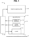
- FIG. 1 illustrates a robotic system 100 for clamping an end effector 110 against a work piece surface (S) with measured clamping force.
- the end effector 110 includes a body 112 and an electromagnetic clamp 114.
- the body 112 and the clamp 114 may be integrated. In other embodiments, the body 112 and the clamp 114 may be separate elements.
- a clamping surface (C) of the end effector 110 will be moved opposite the work piece surface (S).
- the end effector 110 further includes a force sensor 116 for measuring a force exerted by the clamp 114 against the work piece surface (S).
- the force sensor 116 may include a strain gauge, hydraulic sensor, or shape memory sensor. Readings are most accurate when the clamping surface (C) is normal to the work piece surface (S).
- the end effector 110 further includes a plurality of normality sensors 118 positioned about the force sensor 116.
- the normality sensors 118 may be linear displacement sensors. In other embodiments, the normality sensors 118 may be proximity sensors.
- the normality sensors 118 are capable of determining whether the clamping surface (C) is normal to the work piece surface (S) before the force sensor 116 makes contact with the work piece surface (S). This arrangement allows motion of the normality sensors 118 to be decoupled from the force sensor 116 so that the clamping force can be normalized with respect to the work piece surface (S). The force measurements are more accurate when the force sensor 116 is normal to the surface of the work piece. Decoupling the motion further improves the accuracy.
- the force sensor 116 was in contact with the work piece surface while normality was being determined.
- the end effector 110 would require a more complex design including spherical bearings between the force sensor and end effector in order to rotate the clamp while the force sensor was touching the work piece surface (S). Consequently, reactionary forces would wear down the spherical bearings and cause the clamp to shift. Decoupling the motion avoids these problems.
- the system 100 has a simpler design that does not require spherical bearings.
- the robotic system 100 further includes a robotic manipulator 120 for moving the end effector 110.
- the robotic manipulator 120 may include, for example, a robotic arm.
- the robotic system 100 further includes a controller 122 for commanding the robotic manipulator 120 to move the end effector 110.
- the controller 122 also reads the force and normality sensors 116 and 118; and controls the clamp 114 to generate a clamping force.
- the controller 122 may be microprocessor-based.
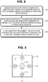
- the controller 122 commands the robotic manipulator 120 to move the end effector 110 opposite the work piece surface (S) until the normality sensors 118 indicate that the clamping surface (C) is normal to the work piece surface (S). During this movement, the force sensor 116 does not make contact with the work piece surface (S).
- the controller 122 commands the robotic manipulator 120 to move the end effector 110 towards the work piece surface (S).
- the controller 122 also uses the normality sensors 118 to ensure that the clamp surface (C) remains normal to the work piece surface (S).
- the controller 122 reads the force sensor 116 to determine when the end effector 110 makes contact with the work piece surface (S). With the clamp normal to the work piece surface (S), the controller 122 commands the clamp 114 to generate a clamping force. The clamping force causes the end effector 110 to be clamped against the work piece surface (S). The controller 122 reads the force sensor 116 and controls the clamp 114 to ensure that a precise clamping force is being applied.
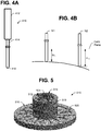
- FIG. 3 shows an embodiment in which four normality sensors 118 are spaced around the force sensor 116.
- a first pair of opposing sensors 118 designated N1 and N2 is located along a first rotational axis (R1).
- a second pair of opposing sensors, designated N3 and N4, is located along a second rotational axis (R2).
- the four normality sensors 118 may be used on planar and non-planar surfaces. In some embodiments, three normality sensors 118 may be used on planar surfaces.
- the normality sensor 410 of Figure 4 may be a linear displacement sensor 412 such as a linear variable differential transformer (LVDT).
- the sensor 410 includes a pin 414 and coil (not shown).
- a tip 416 of the pin 414 is configured to make contact with the surface of a work piece.
- the pin 414 is moved relative to the coil, which senses a voltage. The change in voltage is proportional to the displacement of the pin 414.
- the force and/or normality sensors 116 and 118 may be mounted to the end effector 110 separately from the clamp 114. In other embodiments, one or more of the sensors 116 and 118 may be integrated with the clamp 114.
- the clamp 510 includes a core 516 having a hub 518 and a plate 520.
- An axial passage 522 extends through the hub 518 and the plate 520.
- the force sensor 512 which has a donut shape, is embedded in the hub 518 and surrounds the axial passage 522.
- a bushing 524 retains the force sensor 512 in the hub 518 and extends outward from the hub 518.
- the bushing 524 provides a clamping surface (C). Only the clamping surface (C) of the bushing 524 will make contact with the work piece surface (S).
- the bushing 524 and force sensor 512 may be separate elements. In other embodiments, the bushing 524 and force sensor 512 may be integrated.
- Each linear displacement sensor 514 of the type shown in Figure 4A is spaced around the axial passage 522.
- Each linear displacement sensor is embedded in the hub 518 with a corresponding movable pin.
- the pin can be moved so its tip extends past the clamping surface (C).
- the pin can be moved so its tip is flush with or below the clamping surface (C)
- the normality sensors 514 are arranged in the pattern shown in Figure 3 .
- Two opposing normality sensors 514 (N1 and N2) are located along the first axis R1.
- the other two opposing normality sensors 514 (N3 and N4) are located along the second axis R2.
- Windings 526 are wrapped around the hub 518. When energized, the windings 526 create an electromagnetic field. A shell 528 covers the windings 526.
- the core 510 of Figures 5 and 6 contains several features specific to drilling operations.
- the axial passage 522 allows a drill bit to be inserted therethrough.
- a chip exit port 530 allows chips to be removed during drilling.
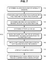
- FIG. 7 illustrates the operation of the electromagnetic clamp 510.
- the operation begins with sensor calibration.
- a calibration plate 810 having a raised portion 812 and lower portion 814 may be used.
- a calibration plane for the normality sensors 514 is determined.
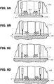
- the clamp 510 is positioned over the calibration plate 810, with the bushing 524 resting on raised portion 812, and all four normality sensors 514 making contact with the lower portion 814 (see Figure 8A ).
- the position of each normality sensor 514 is read and stored. These stored positions define the calibration plane.
- the clamp 510 is removed from the calibration plate 810. As the clamp 510 is removed, the pin tips extend past the calibration plane.
- the clamp 510 is positioned on the surface (S) of the work piece 820.
- the clamp 510 is positioned such that the extended pins of the normality sensors 514 touch the surface (S) (see Figure 8B ).
- the normality sensors 514 are read to determine the distance ⁇ of each tip from the calibration plane.
- Figure 4B shows the distances ⁇ N1 and ( ⁇ N2 for the normality sensors N1 and N2.
- the offset ⁇ A is determined as ⁇ N1- ⁇ N2.
- the offset ⁇ B is determined as ⁇ N3 - ⁇ N4 .
- the force sensor 512 is monitored to determine when the bushing 524 makes contact with the work piece surface (S).
- the winding 526 is energized to generate a clamping force.
- a manufacturing operation is performed while the clamping force is being applied.
- the force sensor 512 is continually read to determine the actual clamping force being applied, and the current to the windings 526 is adjusted to ensure that the precise clamping force is being applied during the manufacturing operation.
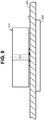
- FIG. 9 illustrates the clamp 510 during a manufacturing operation on a work piece 910 made of composite or other non-metal.
- the clamp 510 may be calibrated and then positioned on one side of the work piece 910, and a metallic backing plate 920 such as a steel plate is positioned on an opposite side of the work piece 910.
- a metallic backing plate 920 such as a steel plate is positioned on an opposite side of the work piece 910.
- the bushing provides a high clamping force around the location that will be drilled.
- the manufacturing operation may include inserting a drill through the axial passage of the clamp 510 and drilling a hole in the work piece 910. As the hole is being drilled, vacuum is applied to the exit port to remove drill chips. After the hole has been drilled, the drill is removed, and a fastener is inserted into the axial passage 522 and through the drilled hole. The clamping force is released, the backing plate 920 removed, and a nut is placed on the fastener.
- Figure 9 may be used during assembly of an aircraft. For instance, it may be used to fasten a spar to panel of a wing box.
- the clamp 510 is used to perform drilling, countersinking and fastener insertion tasks on one side of the panel.
- a person or system inside the wing box on an opposite side of the panel places a sleeve and nut over the inserted fastener.
- U.S. Publication No. 2009/0287352 describes a robotic system that can place a sleeve or nut over a fastener in a confined space that is accessible only through an access port.
Landscapes
- Engineering & Computer Science (AREA)
- Mechanical Engineering (AREA)
- Robotics (AREA)
- Human Computer Interaction (AREA)
- Manipulator (AREA)
Abstract
Description
- During assembly of a commercial aircraft, certain operations are performed synchronously inside and outside of confined spaces. Consider a fastening operation on a spar to panel of a wing box. An assembly system outside the wing box performs drilling, countersinking and fastener insertion tasks on one side of the panel. A person or system inside the wing box on an opposite side of the panel places a sleeve and nut over the inserted fastener.
- During drilling, the assembly system needs to apply a proper clamping force against the panel. If an electromagnet is being used to apply the clamping force, the clamping force may be estimated according to current supplied to the electromagnet's coil. However, the estimation is not always correct. An incorrect estimation can lead to insufficient clamping force.
- If the clamping force is insufficient during a drilling operation, the drill can shift. Consequently, the location of the drilled hole could be out of tolerance. In view of then number of holes that need to be drilled with precision in a commercial aircraft, the cost of out-of-tolerance holes can be quite substantial.
- It would be desirable to accurately measure the clamping force during drilling instead of estimating the clamping force.
- According to an aspect herein, a robotic system comprises an end effector including an electromagnetic clamp, a force sensor attached to the end effector for measuring force exerted by the clamp against a work piece surface, and a plurality of normality sensors. The normality sensors are positioned about the force sensor to determine whether the clamp is normal to the surface before the force sensor makes contact with the surface.
- According to another aspect herein, an electromagnetic clamp comprises a core, windings wrapped around the core, a force sensor at a clamp surface, and a plurality of linear displacement sensors disposed about the force sensor. The linear displacement sensors have tips extending further from the clamp surface than the force sensor, which enables normality of the clamp with respect to a work piece surface to be determined without the force sensor touching the surface.
- According to another aspect herein, a method comprises using a clamp to perform a manufacturing operation on a work piece, where the clamp includes a force sensor for measuring clamping force of the clamp against a surface of the work piece. Using the clamp includes positioning the clamp's clamping surface proximate to the work piece surface, determining normality of the clamping surface with respect to the work piece surface before the clamping surface touches the work piece surface, moving the clamping surface towards the work piece surface while maintaining normality of the clamping surface, and clamping the clamp against the work piece surface.
-
-
Figure 1 is an illustration of a robotic system including an end effector. -
Figure 2 is an illustration of a method of controlling the robotic system to clamp the end effector against a surface of a work piece. -
Figure 3 is an illustration of force and normality sensors with respect to axes of an end effector. -
Figure 4A is an illustration of a normality sensor. -
Figure 4B is an illustration of two normality sensor tips with respect to a calibration plane. -
Figure 5 is an illustration of a core of an electromagnetic clamp with force and normality sensors embedded in the core. -
Figure 6 is an illustration of an electromagnetic clamp including the core ofFigure 5 . -
Figure 7 is an illustration of a method of controlling the electromagnetic clamp ofFigure 6 . -
Figures 8A-8D are illustrations of the electromagnetic clamp ofFigure 6 during calibration, positioning, and clamping. -
Figure 9 is an illustration of the electromagnetic clamp during a manufacturing operation. - Reference is made to
Figure 1 , which illustrates arobotic system 100 for clamping anend effector 110 against a work piece surface (S) with measured clamping force. Theend effector 110 includes abody 112 and anelectromagnetic clamp 114. In some embodiments, thebody 112 and theclamp 114 may be integrated. In other embodiments, thebody 112 and theclamp 114 may be separate elements. - During operation of the
system 100, a clamping surface (C) of theend effector 110 will be moved opposite the work piece surface (S). Theend effector 110 further includes aforce sensor 116 for measuring a force exerted by theclamp 114 against the work piece surface (S). For instance, theforce sensor 116 may include a strain gauge, hydraulic sensor, or shape memory sensor. Readings are most accurate when the clamping surface (C) is normal to the work piece surface (S). - The
end effector 110 further includes a plurality ofnormality sensors 118 positioned about theforce sensor 116. In some embodiments, thenormality sensors 118 may be linear displacement sensors. In other embodiments, thenormality sensors 118 may be proximity sensors. Thenormality sensors 118 are capable of determining whether the clamping surface (C) is normal to the work piece surface (S) before theforce sensor 116 makes contact with the work piece surface (S). This arrangement allows motion of thenormality sensors 118 to be decoupled from theforce sensor 116 so that the clamping force can be normalized with respect to the work piece surface (S). The force measurements are more accurate when theforce sensor 116 is normal to the surface of the work piece. Decoupling the motion further improves the accuracy. Say theforce sensor 116 was in contact with the work piece surface while normality was being determined. Theend effector 110 would require a more complex design including spherical bearings between the force sensor and end effector in order to rotate the clamp while the force sensor was touching the work piece surface (S). Consequently, reactionary forces would wear down the spherical bearings and cause the clamp to shift. Decoupling the motion avoids these problems. In addition to measuring the clamping force with higher accuracy, thesystem 100 has a simpler design that does not require spherical bearings. - The
robotic system 100 further includes arobotic manipulator 120 for moving theend effector 110. Therobotic manipulator 120 may include, for example, a robotic arm. - The
robotic system 100 further includes acontroller 122 for commanding therobotic manipulator 120 to move theend effector 110. Thecontroller 122 also reads the force andnormality sensors clamp 114 to generate a clamping force. Thecontroller 122 may be microprocessor-based. - Reference is now made to
Figure 2 , which illustrates certain functions performed by thecontroller 122. Atblock 210, thecontroller 122 commands therobotic manipulator 120 to move theend effector 110 opposite the work piece surface (S) until thenormality sensors 118 indicate that the clamping surface (C) is normal to the work piece surface (S). During this movement, theforce sensor 116 does not make contact with the work piece surface (S). - At
block 220, thecontroller 122 commands therobotic manipulator 120 to move theend effector 110 towards the work piece surface (S). Thecontroller 122 also uses thenormality sensors 118 to ensure that the clamp surface (C) remains normal to the work piece surface (S). - At
block 230, thecontroller 122 reads theforce sensor 116 to determine when theend effector 110 makes contact with the work piece surface (S). With the clamp normal to the work piece surface (S), thecontroller 122 commands theclamp 114 to generate a clamping force. The clamping force causes theend effector 110 to be clamped against the work piece surface (S). Thecontroller 122 reads theforce sensor 116 and controls theclamp 114 to ensure that a precise clamping force is being applied. - Reference is now made to
Figure 3 , which shows an embodiment in which fournormality sensors 118 are spaced around theforce sensor 116. A first pair of opposingsensors 118, designated N1 and N2, is located along a first rotational axis (R1). A second pair of opposing sensors, designated N3 and N4, is located along a second rotational axis (R2). The fournormality sensors 118 may be used on planar and non-planar surfaces. In some embodiments, threenormality sensors 118 may be used on planar surfaces. - Reference is now made to
Figure 4A , which illustrates an embodiment of anormality sensor 410. Thenormality sensor 410 ofFigure 4 may be alinear displacement sensor 412 such as a linear variable differential transformer (LVDT). Thesensor 410 includes apin 414 and coil (not shown). Atip 416 of thepin 414 is configured to make contact with the surface of a work piece. During operation, thepin 414 is moved relative to the coil, which senses a voltage. The change in voltage is proportional to the displacement of thepin 414. - In some embodiments, the force and/or
normality sensors end effector 110 separately from theclamp 114. In other embodiments, one or more of thesensors clamp 114. - Reference is now made to
Figures 5 and6 , which illustrate an embodiment of anelectromagnetic clamp 510 with integrated force andnormality sensors clamp 510 includes acore 516 having ahub 518 and aplate 520. Anaxial passage 522 extends through thehub 518 and theplate 520. - The
force sensor 512, which has a donut shape, is embedded in thehub 518 and surrounds theaxial passage 522. Abushing 524 retains theforce sensor 512 in thehub 518 and extends outward from thehub 518. Thebushing 524 provides a clamping surface (C). Only the clamping surface (C) of thebushing 524 will make contact with the work piece surface (S). In some embodiments, thebushing 524 andforce sensor 512 may be separate elements. In other embodiments, thebushing 524 andforce sensor 512 may be integrated. - Four
normality sensors 514 of the type shown inFigure 4A are spaced around theaxial passage 522. Each linear displacement sensor is embedded in thehub 518 with a corresponding movable pin. The pin can be moved so its tip extends past the clamping surface (C). The pin can be moved so its tip is flush with or below the clamping surface (C) - The
normality sensors 514 are arranged in the pattern shown inFigure 3 . Two opposing normality sensors 514 (N1 and N2) are located along the first axis R1. The other two opposing normality sensors 514 (N3 and N4) are located along the second axis R2. -
Windings 526 are wrapped around thehub 518. When energized, thewindings 526 create an electromagnetic field. Ashell 528 covers thewindings 526. - The
core 510 ofFigures 5 and6 contains several features specific to drilling operations. Theaxial passage 522 allows a drill bit to be inserted therethrough. A chip exit port 530 allows chips to be removed during drilling. - Additional reference is now made to
Figure 7 , which illustrates the operation of theelectromagnetic clamp 510. The operation begins with sensor calibration. Acalibration plate 810 having a raisedportion 812 andlower portion 814 may be used. - At
block 710, a calibration plane for thenormality sensors 514 is determined. Theclamp 510 is positioned over thecalibration plate 810, with thebushing 524 resting on raisedportion 812, and all fournormality sensors 514 making contact with the lower portion 814 (seeFigure 8A ). The position of eachnormality sensor 514 is read and stored. These stored positions define the calibration plane. - Sensor calibration having been completed, the
clamp 510 is removed from thecalibration plate 810. As theclamp 510 is removed, the pin tips extend past the calibration plane. - Next, the
clamp 510 is positioned on the surface (S) of thework piece 820. Atblock 720, theclamp 510 is positioned such that the extended pins of thenormality sensors 514 touch the surface (S) (seeFigure 8B ). Atblock 730, thenormality sensors 514 are read to determine the distance ϕ of each tip from the calibration plane.Figure 4B shows the distances ϕN1 and (ϕN2 for the normality sensors N1 and N2. - At
block 740, the offset ΔA is determined as ϕN1-ϕN2. Similarly, the offset ΔB is determined as ϕN3-ϕN4. - At
block 750, theclamp 510 is manipulated until the tips of opposing sensors have the same distance from the calibration plane. That is, the clamp is moved until both ΔA=0 and ΔB=0 (seeFigure 8C ). When ΔA=0 and ΔB=0, the clamping surface (C) is considered normal to the work piece surface (S). - At
block 760, theclamp 514 is moved toward the work piece surface (S), ensuring that ΔA and ΔB remain at ΔA =0 and ΔB=0. In this manner, the clamping surface (C) stays normal as it is being moved towards the work piece surface (S). Theforce sensor 512 is monitored to determine when thebushing 524 makes contact with the work piece surface (S). - Motion of the
clamp 510 is stopped when theforce sensor 512 indicates that thebushing 524 touches the work piece surface (S) (seeFigure 8D ). At this point, theclamp 510 is normal to the surface (S), but a clamping force has yet to be applied. - At
block 770, the winding 526 is energized to generate a clamping force. Atblock 780, a manufacturing operation is performed while the clamping force is being applied. Atblocks force sensor 512 is continually read to determine the actual clamping force being applied, and the current to thewindings 526 is adjusted to ensure that the precise clamping force is being applied during the manufacturing operation. - Reference is now made to
Figure 9 , which illustrates theclamp 510 during a manufacturing operation on awork piece 910 made of composite or other non-metal. Theclamp 510 may be calibrated and then positioned on one side of thework piece 910, and ametallic backing plate 920 such as a steel plate is positioned on an opposite side of thework piece 910. When the windings of theclamp 510 are energized, thework piece 910 is clamped between theclamp 510 and thebacking plate 920. The bushing provides a high clamping force around the location that will be drilled. - The manufacturing operation may include inserting a drill through the axial passage of the
clamp 510 and drilling a hole in thework piece 910. As the hole is being drilled, vacuum is applied to the exit port to remove drill chips. After the hole has been drilled, the drill is removed, and a fastener is inserted into theaxial passage 522 and through the drilled hole. The clamping force is released, thebacking plate 920 removed, and a nut is placed on the fastener. - The manufacturing operation of
Figure 9 may be used during assembly of an aircraft. For instance, it may be used to fasten a spar to panel of a wing box. Theclamp 510 is used to perform drilling, countersinking and fastener insertion tasks on one side of the panel. A person or system inside the wing box on an opposite side of the panel places a sleeve and nut over the inserted fastener.U.S. Publication No. 2009/0287352 describes a robotic system that can place a sleeve or nut over a fastener in a confined space that is accessible only through an access port.
Claims (17)
- A robotic system comprising:an end effector including an electromagnetic clamp;a force sensor attached to the end effector for measuring force exerted by the clamp against a work piece surface; anda plurality of normality sensors positioned about the force sensor for determining whether the clamp is normal to the surface before the force sensor makes contact with the surface.
- The system of claim1, wherein the normality sensors include at least three sensors for measuring orientation about first and second rotational axes of the clamp.
- The system of any preceding claim, further comprising:a robotic manipulator for moving the end effector; anda controller, responsive to outputs of the normality sensors, for commanding the robotic manipulator to move the end effector until the clamp is normal to the work piece surface without allowing the force sensor to make contact with the work piece surface.
- The system of claim 3, wherein the controller commands the clamp to generate a clamping force in response to an output of the force sensor.
- The system of claim 3 or 4, further comprising a calibration plate for calibrating positions of the normality sensors, the calibration plate having a raised portion upon which the force sensor rests and a lower portion upon which defines a calibration plane for the tips of the normality sensors.
- The system of claim 3 or 4, wherein the controller determines a calibration plane for the normality sensors; moves the clamp onto a work piece surface, determines pin distances from the calibration plane, and then orients the clamp so the distances of opposing normality sensors are equal.
- The system of any preceding claim, wherein the force sensor is located at a surface of the clamp; and wherein each normality sensor includes a pin and a linear displacement sensor for determining position of the pin, each pin movable so its tip can extend beyond the clamp surface.
- The system of any preceding claim, wherein the force and normality sensors are integrated with the clamp.
- An electromagnetic clamp comprising:a core;windings wrapped around the core;a force sensor at a clamp surface; anda plurality of linear displacement sensors disposed about the force sensor, the linear displacement sensors having tips extending further from the clamp surface than the force sensor, which enables normality of the clamp with respect to a work piece surface to be determined without the force sensor touching the surface.
- The clamp of claim 9, wherein four linear displacement sensors are disposed about the force sensor.
- The clamp of claim 9 or 10, wherein each linear displacement sensor includes a linear variable differential transformer (LVDT) embedded in the core and a pin extending from the LVDT.
- The clamp of claim 9, 10, or 11, further comprising a bushing for securing the force sensor to the core, wherein the bushing provides the clamp surface.
- A method of using the clamp of any claim 9 to 12, comprising:determining a calibration plane for the linear displacement sensors;positioning the clamp over a work piece with the tips of all normality sensors touching the work piece surface;determining distance of each tip from the calibration plane;re-orienting the clamp until distances of opposing sensors are equal;moving the clamp towards the work piece surface until the clamp surface touches the work piece surface while maintaining the distances; andapplying the clamping force.
- A method of using the clamp of claim 13, further comprising performing a manufacturing operation on the work piece, including:inserting a drill through an axial opening in the core, andusing the drill to drill a hole in the work piece while reading the force sensor and controlling the winding to ensure that a precise clamping force is applied during drilling.
- A method comprising using a clamp to perform a manufacturing operation on a work piece, the clamp including a force sensor for measuring clamping force of the clamp against a surface of the work piece, wherein using the clamp includes:positioning the clamp's clamping surface proximate to the work piece surface;determining normality of the clamping surface with respect to the work piece surface before the clamping surface touches the work piece surface;moving the clamping surface towards the work piece surface while maintaining normality of the clamping surface; andclamping the clamp against the work piece surface.
- The method of claim 15, wherein the manufacturing operation includes a drilling operation.
- The method of claim 15 or 16, wherein the work piece includes a composite aircraft panel; the method further comprising placing a metal backing panel behind the composite panel.
Applications Claiming Priority (1)
| Application Number | Priority Date | Filing Date | Title |
|---|---|---|---|
| US13/032,596 US8573070B2 (en) | 2011-02-22 | 2011-02-22 | Force and normality sensing for end effector clamp |
Publications (2)
| Publication Number | Publication Date |
|---|---|
| EP2492065A1 true EP2492065A1 (en) | 2012-08-29 |
| EP2492065B1 EP2492065B1 (en) | 2014-07-16 |
Family
ID=45656210
Family Applications (1)
| Application Number | Title | Priority Date | Filing Date |
|---|---|---|---|
| EP12156213.6A Active EP2492065B1 (en) | 2011-02-22 | 2012-02-20 | Force and normality sensing for end effector clamp |
Country Status (4)
| Country | Link |
|---|---|
| US (1) | US8573070B2 (en) |
| EP (1) | EP2492065B1 (en) |
| JP (1) | JP5967972B2 (en) |
| CN (1) | CN102649169B (en) |
Cited By (4)
| Publication number | Priority date | Publication date | Assignee | Title |
|---|---|---|---|---|
| EP2808110A1 (en) * | 2013-05-27 | 2014-12-03 | Fuji Jukogyo Kabushiki Kaisha | Drilling apparatus and drilling method |
| EP3002088A3 (en) * | 2014-10-02 | 2016-06-01 | Airbus Operations, S.L. | Orthogonal positioning instrument, system and method for automatic machines |
| US11084171B2 (en) | 2017-11-22 | 2021-08-10 | Fanuc Corporation | Tool posture control apparatus |
| FR3129618A1 (en) * | 2021-11-29 | 2023-06-02 | Psa Automobiles Sa | magnetic gripping tool |
Families Citing this family (47)
| Publication number | Priority date | Publication date | Assignee | Title |
|---|---|---|---|---|
| US8096038B2 (en) | 2007-05-11 | 2012-01-17 | The Boeing Company | Robotic end effector and clamping method |
| US20100180711A1 (en) | 2009-01-19 | 2010-07-22 | Comau, Inc. | Robotic end effector system and method |
| US8626458B2 (en) * | 2009-11-05 | 2014-01-07 | Vibration Technologies, Llc | Method and system for measuring the dynamic response of a structure during a machining process |
| JP2014073571A (en) * | 2012-10-05 | 2014-04-24 | Mitsubishi Heavy Ind Ltd | Surface direct copying mechanism, and machining device and machining method with the same |
| US10065280B2 (en) | 2012-10-30 | 2018-09-04 | The Boeing Company | Multifunction legs for autonomous crawling assembly equipment |
| US9327376B2 (en) | 2012-10-30 | 2016-05-03 | The Boeing Company | Dual function movement component for automated assembly systems |
| US9475527B2 (en) | 2012-10-30 | 2016-10-25 | The Boeing Company | Autonomous crawling assembly system |
| US9488971B2 (en) | 2013-03-11 | 2016-11-08 | The Board Of Trustees Of The Leland Stanford Junior University | Model-less control for flexible manipulators |
| ES2602328T3 (en) * | 2013-07-01 | 2017-02-20 | Comau S.P.A. | Tool head for industrial operations that has a wireless monitoring system |
| CN104552322A (en) * | 2013-10-28 | 2015-04-29 | 精工爱普生株式会社 | Gripping apparatus, robot, and gripping method |
| CN104608128A (en) * | 2013-11-01 | 2015-05-13 | 精工爱普生株式会社 | Robot, control device, robot system and robot control method |
| US10427254B2 (en) | 2014-04-30 | 2019-10-01 | The Boeing Company | Flexible manufacturing for aircraft structures |
| US9776330B2 (en) | 2014-04-30 | 2017-10-03 | The Boeing Company | Crawler robot and supporting platform |
| US9486917B2 (en) | 2014-04-30 | 2016-11-08 | The Boeing Company | Mobile automated assembly tool for aircraft structures |
| US9708079B2 (en) | 2014-04-30 | 2017-07-18 | The Boeing Company | Mobile automated overhead assembly tool for aircraft structures |
| US10118714B2 (en) | 2014-04-30 | 2018-11-06 | The Boeing Company | System and method for positioning an automated assembly tool relative to a structure |
| US10017277B2 (en) | 2014-04-30 | 2018-07-10 | The Boeing Company | Apparatus, system, and method for supporting a wing assembly |
| US10000298B2 (en) | 2014-04-30 | 2018-06-19 | The Boeing Company | Metrology system for positioning assemblies |
| US10691097B2 (en) | 2014-05-09 | 2020-06-23 | The Boeing Company | Path repeatable machining for full sized determinant assembly |
| US10434644B2 (en) | 2014-11-03 | 2019-10-08 | The Board Of Trustees Of The Leland Stanford Junior University | Position/force control of a flexible manipulator under model-less control |
| JP5937706B1 (en) | 2015-01-21 | 2016-06-22 | ファナック株式会社 | Robot control apparatus and robot system for controlling robot based on external force applied to robot |
| JP6693098B2 (en) * | 2015-11-26 | 2020-05-13 | セイコーエプソン株式会社 | Robots and robot systems |
| CN106041926B (en) * | 2016-06-12 | 2018-10-19 | 哈尔滨工程大学 | A kind of industrial machinery arm strength/Position Hybrid Control method based on Kalman filter |
| US10494241B2 (en) * | 2016-09-16 | 2019-12-03 | Cascade Corporation | Hydraulic clamping systems having load side-shifting variably responsive to load weight |
| EP3305431B1 (en) | 2016-10-10 | 2023-09-27 | Comau S.p.A. | Hemming apparatus and hemming method |
| US10710747B2 (en) | 2016-11-30 | 2020-07-14 | The Boeing Company | Compound contour vacuum track for automation of final assembly from the interior of a fuselage |
| US10723484B2 (en) * | 2016-11-30 | 2020-07-28 | The Boeing Company | Automated fastening machine using a compound contour vacuum track for automation of final assembly from the interior of a fuselage |
| PL3366409T3 (en) | 2017-02-23 | 2019-12-31 | Comau S.P.A. | Articulated robot carrying an electric resistance welding head with electrodes located on the same side ; corresponding method of resistance electric welding on a component to be welded |
| DE102017106455B3 (en) * | 2017-03-27 | 2018-09-20 | Abb Schweiz Ag | End effector for workpiece machining and robot system with an end effector |
| CN111093891B (en) * | 2017-04-27 | 2022-08-02 | 磁转换技术全球私人有限公司 | Magnetic coupling device with at least one sensor arrangement and degaussing capability |
| WO2018223148A2 (en) * | 2017-06-02 | 2018-12-06 | The Research Foundation For The State University Of New York | Robotic gripper with variable stiffness actuators and methods for same |
| JP6860534B2 (en) * | 2017-11-22 | 2021-04-14 | ファナック株式会社 | Tool attitude control device |
| DE202017107536U1 (en) * | 2017-12-11 | 2018-01-15 | Bystronic Laser Ag | Fastening device for machine tools and machine tool with a fastening device |
| EP3833515A1 (en) * | 2018-08-09 | 2021-06-16 | ABB Schweiz AG | Method for estimating a wrench |
| WO2020041819A1 (en) * | 2018-08-29 | 2020-03-05 | Fastbrick Ip Pty Ltd | Gripping apparatus |
| US10472095B1 (en) | 2018-09-07 | 2019-11-12 | The Boeing Company | Mobile fixture apparatuses and methods |
| US10782696B2 (en) | 2018-09-07 | 2020-09-22 | The Boeing Company | Mobile fixture apparatuses and methods |
| US11072439B2 (en) | 2018-09-07 | 2021-07-27 | The Boeing Company | Mobile fixture apparatuses and methods |
| CN109759950A (en) * | 2019-02-14 | 2019-05-17 | 上海理工大学 | A kind of wheel hub bearing grinding clamping force measuring device and measuring method |
| US11167381B2 (en) * | 2020-01-31 | 2021-11-09 | GM Global Technology Operations LLC | Clamp system and method for control of welding a first substrate to a second substrate |
| GB2594503A (en) * | 2020-04-30 | 2021-11-03 | Airbus Operations Ltd | Automated clamp |
| CN112223283B (en) * | 2020-09-29 | 2024-06-25 | 腾讯科技(深圳)有限公司 | Robotic arm, robot, control method of robotic arm, processing equipment and medium |
| CN112792458B (en) * | 2020-12-31 | 2024-08-30 | 广州德志金属制品有限公司 | Laser printing device and laser printing method |
| CN114055507B (en) * | 2021-12-09 | 2023-04-18 | 厦门大学 | Operation method of flexible gripping device for industrial robot |
| US20240066709A1 (en) * | 2022-08-23 | 2024-02-29 | The Boeing Company | Normalizing Nosepiece Assembly for an End Effector |
| EP4679482A1 (en) * | 2024-07-12 | 2026-01-14 | ASML Netherlands B.V. | Module, apparatus, and method of using the module |
| WO2025261728A1 (en) * | 2024-06-17 | 2025-12-26 | Asml Netherlands B.V. | Module, apparatus, and method of using the module |
Citations (4)
| Publication number | Priority date | Publication date | Assignee | Title |
|---|---|---|---|---|
| US20020050043A1 (en) * | 2000-03-09 | 2002-05-02 | The Boeing Company | Apparatus and method for installing fasteners in a workpiece |
| US20060143890A1 (en) * | 2004-10-26 | 2006-07-06 | Airbus Deutschland Gmbh | Device for processing components for means of transport, in particular for processing sections for aircraft |
| US20090287352A1 (en) | 2008-05-15 | 2009-11-19 | Carnegie Mellon University | Robotic system including foldable robotic arm |
| US20100204817A1 (en) * | 2007-09-13 | 2010-08-12 | Mitsubishi Heavy Industries, Ltd. | Posture control method and posture control device |
Family Cites Families (14)
| Publication number | Priority date | Publication date | Assignee | Title |
|---|---|---|---|---|
| US3891918A (en) * | 1971-03-23 | 1975-06-24 | James F Ellis | Linear displacement transducer utilizing an oscillator whose average period varies as a linear function of the displacement |
| JPH01257579A (en) * | 1988-04-06 | 1989-10-13 | Hitachi Ltd | manipulator |
| JP3055976B2 (en) * | 1991-08-28 | 2000-06-26 | 株式会社日立製作所 | Manipulator device with torque supply device |
| US5297760A (en) * | 1992-08-21 | 1994-03-29 | Mcdonnell Douglas Corporation | Aircraft skin lap splice |
| JPH06305608A (en) * | 1993-04-21 | 1994-11-01 | Toyota Motor Corp | Work suction device |
| JP3486721B2 (en) * | 1995-02-16 | 2004-01-13 | 三明電機株式会社 | Work sensor |
| US5888032A (en) * | 1996-09-13 | 1999-03-30 | Cooper Technologies Company | Paddle fitting tool |
| JP2000062980A (en) * | 1998-08-20 | 2000-02-29 | Amada Co Ltd | Single sheet picking method and apparatus |
| GB2356291B (en) * | 1999-11-13 | 2003-10-22 | Rolls Royce Plc | A workpiece clamping system |
| DE10318798B4 (en) * | 2003-04-25 | 2006-01-26 | Robert Bosch Gmbh | drill |
| US7148776B2 (en) | 2003-04-28 | 2006-12-12 | The Boeing Company | Electromagnetic clamp and method for clamping a structure |
| US7088210B2 (en) | 2004-01-23 | 2006-08-08 | The Boeing Company | Electromagnet having spacer for facilitating cooling and associated cooling method |
| ES2338622B1 (en) * | 2008-07-23 | 2011-07-01 | Estudios De Ingenieria Adaptada, S.L. | TOOL POSITIONING HEAD ON IRREGULAR SURFACES. |
| CN101417348B (en) * | 2008-11-24 | 2010-06-23 | 北京航空航天大学 | Drill end actuator |
-
2011
- 2011-02-22 US US13/032,596 patent/US8573070B2/en active Active
-
2012
- 2012-02-20 EP EP12156213.6A patent/EP2492065B1/en active Active
- 2012-02-21 JP JP2012035495A patent/JP5967972B2/en active Active
- 2012-02-22 CN CN201210042188.7A patent/CN102649169B/en active Active
Patent Citations (4)
| Publication number | Priority date | Publication date | Assignee | Title |
|---|---|---|---|---|
| US20020050043A1 (en) * | 2000-03-09 | 2002-05-02 | The Boeing Company | Apparatus and method for installing fasteners in a workpiece |
| US20060143890A1 (en) * | 2004-10-26 | 2006-07-06 | Airbus Deutschland Gmbh | Device for processing components for means of transport, in particular for processing sections for aircraft |
| US20100204817A1 (en) * | 2007-09-13 | 2010-08-12 | Mitsubishi Heavy Industries, Ltd. | Posture control method and posture control device |
| US20090287352A1 (en) | 2008-05-15 | 2009-11-19 | Carnegie Mellon University | Robotic system including foldable robotic arm |
Cited By (4)
| Publication number | Priority date | Publication date | Assignee | Title |
|---|---|---|---|---|
| EP2808110A1 (en) * | 2013-05-27 | 2014-12-03 | Fuji Jukogyo Kabushiki Kaisha | Drilling apparatus and drilling method |
| EP3002088A3 (en) * | 2014-10-02 | 2016-06-01 | Airbus Operations, S.L. | Orthogonal positioning instrument, system and method for automatic machines |
| US11084171B2 (en) | 2017-11-22 | 2021-08-10 | Fanuc Corporation | Tool posture control apparatus |
| FR3129618A1 (en) * | 2021-11-29 | 2023-06-02 | Psa Automobiles Sa | magnetic gripping tool |
Also Published As
| Publication number | Publication date |
|---|---|
| US8573070B2 (en) | 2013-11-05 |
| JP5967972B2 (en) | 2016-08-10 |
| JP2012171093A (en) | 2012-09-10 |
| EP2492065B1 (en) | 2014-07-16 |
| CN102649169A (en) | 2012-08-29 |
| US20120210802A1 (en) | 2012-08-23 |
| CN102649169B (en) | 2016-08-10 |
Similar Documents
| Publication | Publication Date | Title |
|---|---|---|
| US8573070B2 (en) | Force and normality sensing for end effector clamp | |
| JP2012171093A5 (en) | ||
| US4694230A (en) | Micromanipulator system | |
| Denkena et al. | Feeling machines for online detection and compensation of tool deflection in milling | |
| JP4873613B2 (en) | Spatial reference system | |
| US9199351B2 (en) | Drilling machine having hole measurement capability | |
| US20180264614A1 (en) | Linear guiding device for a feed axis of a machine tool | |
| JP5355579B2 (en) | Tool holder and stepwise sheet forming method using the tool holder | |
| EP2645052B1 (en) | Measurement head for feeler for workpieces being machined | |
| EP3437755B1 (en) | Riveting machine and control method for same | |
| US7070375B2 (en) | Clamping fastener grip length indicator | |
| Breitzke et al. | Workshop-suited geometric errors identification of three-axis machine tools using on-machine measurement for long term precision assurance | |
| JP2023182816A (en) | Plug gauge for performing multiple diameter measurements simultaneously, and related systems and methods | |
| CN101726226A (en) | Measuring device for true position of unloading hole of shell of power steering gear of automobile | |
| US20090150109A1 (en) | Calibration procedure for rivet height gages | |
| EP2827098A1 (en) | Normal detection method, normal detection device, and machining machine provided with normal detection function | |
| CN201130003Y (en) | Internal groove bottom diameter detection device | |
| CN107991177A (en) | A kind of method for testing the surrender of sheet metal twin shaft and Temperature measurement | |
| CN113400089A (en) | Error sensing compensation method for precision machining | |
| CN109141187B (en) | Small Aperture Measuring Tool | |
| CN113483613B (en) | Handheld hole normal vector precision detection device and method | |
| JP2018017519A (en) | Position gauge, centering device and centering method | |
| JP2025520747A (en) | Method and system for locating points on a surface - Patents.com | |
| CN210452057U (en) | Machining center tool changing position precision rapid detection tool | |
| CN114193232A (en) | Five-axis tool nose following function precision measuring device and method for heavy floor type boring and milling machine |
Legal Events
| Date | Code | Title | Description |
|---|---|---|---|
| PUAI | Public reference made under article 153(3) epc to a published international application that has entered the european phase |
Free format text: ORIGINAL CODE: 0009012 |
|
| 17P | Request for examination filed |
Effective date: 20120220 |
|
| AK | Designated contracting states |
Kind code of ref document: A1 Designated state(s): AL AT BE BG CH CY CZ DE DK EE ES FI FR GB GR HR HU IE IS IT LI LT LU LV MC MK MT NL NO PL PT RO RS SE SI SK SM TR |
|
| AX | Request for extension of the european patent |
Extension state: BA ME |
|
| GRAP | Despatch of communication of intention to grant a patent |
Free format text: ORIGINAL CODE: EPIDOSNIGR1 |
|
| INTG | Intention to grant announced |
Effective date: 20140128 |
|
| GRAS | Grant fee paid |
Free format text: ORIGINAL CODE: EPIDOSNIGR3 |
|
| GRAA | (expected) grant |
Free format text: ORIGINAL CODE: 0009210 |
|
| AK | Designated contracting states |
Kind code of ref document: B1 Designated state(s): AL AT BE BG CH CY CZ DE DK EE ES FI FR GB GR HR HU IE IS IT LI LT LU LV MC MK MT NL NO PL PT RO RS SE SI SK SM TR |
|
| REG | Reference to a national code |
Ref country code: GB Ref legal event code: FG4D |
|
| REG | Reference to a national code |
Ref country code: CH Ref legal event code: EP |
|
| REG | Reference to a national code |
Ref country code: IE Ref legal event code: FG4D |
|
| REG | Reference to a national code |
Ref country code: AT Ref legal event code: REF Ref document number: 677308 Country of ref document: AT Kind code of ref document: T Effective date: 20140815 |
|
| REG | Reference to a national code |
Ref country code: DE Ref legal event code: R096 Ref document number: 602012002386 Country of ref document: DE Effective date: 20140828 |
|
| REG | Reference to a national code |
Ref country code: NL Ref legal event code: VDEP Effective date: 20140716 |
|
| REG | Reference to a national code |
Ref country code: AT Ref legal event code: MK05 Ref document number: 677308 Country of ref document: AT Kind code of ref document: T Effective date: 20140716 |
|
| REG | Reference to a national code |
Ref country code: LT Ref legal event code: MG4D |
|
| PG25 | Lapsed in a contracting state [announced via postgrant information from national office to epo] |
Ref country code: BG Free format text: LAPSE BECAUSE OF FAILURE TO SUBMIT A TRANSLATION OF THE DESCRIPTION OR TO PAY THE FEE WITHIN THE PRESCRIBED TIME-LIMIT Effective date: 20141016 Ref country code: SE Free format text: LAPSE BECAUSE OF FAILURE TO SUBMIT A TRANSLATION OF THE DESCRIPTION OR TO PAY THE FEE WITHIN THE PRESCRIBED TIME-LIMIT Effective date: 20140716 Ref country code: PT Free format text: LAPSE BECAUSE OF FAILURE TO SUBMIT A TRANSLATION OF THE DESCRIPTION OR TO PAY THE FEE WITHIN THE PRESCRIBED TIME-LIMIT Effective date: 20141117 Ref country code: FI Free format text: LAPSE BECAUSE OF FAILURE TO SUBMIT A TRANSLATION OF THE DESCRIPTION OR TO PAY THE FEE WITHIN THE PRESCRIBED TIME-LIMIT Effective date: 20140716 Ref country code: NO Free format text: LAPSE BECAUSE OF FAILURE TO SUBMIT A TRANSLATION OF THE DESCRIPTION OR TO PAY THE FEE WITHIN THE PRESCRIBED TIME-LIMIT Effective date: 20141016 Ref country code: LT Free format text: LAPSE BECAUSE OF FAILURE TO SUBMIT A TRANSLATION OF THE DESCRIPTION OR TO PAY THE FEE WITHIN THE PRESCRIBED TIME-LIMIT Effective date: 20140716 Ref country code: GR Free format text: LAPSE BECAUSE OF FAILURE TO SUBMIT A TRANSLATION OF THE DESCRIPTION OR TO PAY THE FEE WITHIN THE PRESCRIBED TIME-LIMIT Effective date: 20141017 Ref country code: ES Free format text: LAPSE BECAUSE OF FAILURE TO SUBMIT A TRANSLATION OF THE DESCRIPTION OR TO PAY THE FEE WITHIN THE PRESCRIBED TIME-LIMIT Effective date: 20140716 |
|
| PG25 | Lapsed in a contracting state [announced via postgrant information from national office to epo] |
Ref country code: PL Free format text: LAPSE BECAUSE OF FAILURE TO SUBMIT A TRANSLATION OF THE DESCRIPTION OR TO PAY THE FEE WITHIN THE PRESCRIBED TIME-LIMIT Effective date: 20140716 Ref country code: NL Free format text: LAPSE BECAUSE OF FAILURE TO SUBMIT A TRANSLATION OF THE DESCRIPTION OR TO PAY THE FEE WITHIN THE PRESCRIBED TIME-LIMIT Effective date: 20140716 Ref country code: LV Free format text: LAPSE BECAUSE OF FAILURE TO SUBMIT A TRANSLATION OF THE DESCRIPTION OR TO PAY THE FEE WITHIN THE PRESCRIBED TIME-LIMIT Effective date: 20140716 Ref country code: IS Free format text: LAPSE BECAUSE OF FAILURE TO SUBMIT A TRANSLATION OF THE DESCRIPTION OR TO PAY THE FEE WITHIN THE PRESCRIBED TIME-LIMIT Effective date: 20141116 Ref country code: RS Free format text: LAPSE BECAUSE OF FAILURE TO SUBMIT A TRANSLATION OF THE DESCRIPTION OR TO PAY THE FEE WITHIN THE PRESCRIBED TIME-LIMIT Effective date: 20140716 Ref country code: CY Free format text: LAPSE BECAUSE OF FAILURE TO SUBMIT A TRANSLATION OF THE DESCRIPTION OR TO PAY THE FEE WITHIN THE PRESCRIBED TIME-LIMIT Effective date: 20140716 Ref country code: AT Free format text: LAPSE BECAUSE OF FAILURE TO SUBMIT A TRANSLATION OF THE DESCRIPTION OR TO PAY THE FEE WITHIN THE PRESCRIBED TIME-LIMIT Effective date: 20140716 |
|
| REG | Reference to a national code |
Ref country code: DE Ref legal event code: R097 Ref document number: 602012002386 Country of ref document: DE |
|
| PG25 | Lapsed in a contracting state [announced via postgrant information from national office to epo] |
Ref country code: CZ Free format text: LAPSE BECAUSE OF FAILURE TO SUBMIT A TRANSLATION OF THE DESCRIPTION OR TO PAY THE FEE WITHIN THE PRESCRIBED TIME-LIMIT Effective date: 20140716 Ref country code: EE Free format text: LAPSE BECAUSE OF FAILURE TO SUBMIT A TRANSLATION OF THE DESCRIPTION OR TO PAY THE FEE WITHIN THE PRESCRIBED TIME-LIMIT Effective date: 20140716 Ref country code: IT Free format text: LAPSE BECAUSE OF FAILURE TO SUBMIT A TRANSLATION OF THE DESCRIPTION OR TO PAY THE FEE WITHIN THE PRESCRIBED TIME-LIMIT Effective date: 20140716 Ref country code: SK Free format text: LAPSE BECAUSE OF FAILURE TO SUBMIT A TRANSLATION OF THE DESCRIPTION OR TO PAY THE FEE WITHIN THE PRESCRIBED TIME-LIMIT Effective date: 20140716 Ref country code: DK Free format text: LAPSE BECAUSE OF FAILURE TO SUBMIT A TRANSLATION OF THE DESCRIPTION OR TO PAY THE FEE WITHIN THE PRESCRIBED TIME-LIMIT Effective date: 20140716 Ref country code: RO Free format text: LAPSE BECAUSE OF FAILURE TO SUBMIT A TRANSLATION OF THE DESCRIPTION OR TO PAY THE FEE WITHIN THE PRESCRIBED TIME-LIMIT Effective date: 20140716 |
|
| PLBE | No opposition filed within time limit |
Free format text: ORIGINAL CODE: 0009261 |
|
| STAA | Information on the status of an ep patent application or granted ep patent |
Free format text: STATUS: NO OPPOSITION FILED WITHIN TIME LIMIT |
|
| 26N | No opposition filed |
Effective date: 20150417 |
|
| PG25 | Lapsed in a contracting state [announced via postgrant information from national office to epo] |
Ref country code: BE Free format text: LAPSE BECAUSE OF NON-PAYMENT OF DUE FEES Effective date: 20150228 |
|
| PG25 | Lapsed in a contracting state [announced via postgrant information from national office to epo] |
Ref country code: LU Free format text: LAPSE BECAUSE OF FAILURE TO SUBMIT A TRANSLATION OF THE DESCRIPTION OR TO PAY THE FEE WITHIN THE PRESCRIBED TIME-LIMIT Effective date: 20150220 |
|
| REG | Reference to a national code |
Ref country code: CH Ref legal event code: PL |
|
| PG25 | Lapsed in a contracting state [announced via postgrant information from national office to epo] |
Ref country code: LI Free format text: LAPSE BECAUSE OF NON-PAYMENT OF DUE FEES Effective date: 20150228 Ref country code: CH Free format text: LAPSE BECAUSE OF NON-PAYMENT OF DUE FEES Effective date: 20150228 Ref country code: MC Free format text: LAPSE BECAUSE OF FAILURE TO SUBMIT A TRANSLATION OF THE DESCRIPTION OR TO PAY THE FEE WITHIN THE PRESCRIBED TIME-LIMIT Effective date: 20140716 |
|
| REG | Reference to a national code |
Ref country code: IE Ref legal event code: MM4A |
|
| PG25 | Lapsed in a contracting state [announced via postgrant information from national office to epo] |
Ref country code: SI Free format text: LAPSE BECAUSE OF FAILURE TO SUBMIT A TRANSLATION OF THE DESCRIPTION OR TO PAY THE FEE WITHIN THE PRESCRIBED TIME-LIMIT Effective date: 20140716 |
|
| PG25 | Lapsed in a contracting state [announced via postgrant information from national office to epo] |
Ref country code: IE Free format text: LAPSE BECAUSE OF NON-PAYMENT OF DUE FEES Effective date: 20150220 |
|
| REG | Reference to a national code |
Ref country code: FR Ref legal event code: PLFP Year of fee payment: 5 |
|
| PG25 | Lapsed in a contracting state [announced via postgrant information from national office to epo] |
Ref country code: BE Free format text: LAPSE BECAUSE OF FAILURE TO SUBMIT A TRANSLATION OF THE DESCRIPTION OR TO PAY THE FEE WITHIN THE PRESCRIBED TIME-LIMIT Effective date: 20140716 |
|
| PG25 | Lapsed in a contracting state [announced via postgrant information from national office to epo] |
Ref country code: MT Free format text: LAPSE BECAUSE OF FAILURE TO SUBMIT A TRANSLATION OF THE DESCRIPTION OR TO PAY THE FEE WITHIN THE PRESCRIBED TIME-LIMIT Effective date: 20140716 |
|
| REG | Reference to a national code |
Ref country code: FR Ref legal event code: PLFP Year of fee payment: 6 |
|
| PG25 | Lapsed in a contracting state [announced via postgrant information from national office to epo] |
Ref country code: HU Free format text: LAPSE BECAUSE OF FAILURE TO SUBMIT A TRANSLATION OF THE DESCRIPTION OR TO PAY THE FEE WITHIN THE PRESCRIBED TIME-LIMIT; INVALID AB INITIO Effective date: 20120220 Ref country code: SM Free format text: LAPSE BECAUSE OF FAILURE TO SUBMIT A TRANSLATION OF THE DESCRIPTION OR TO PAY THE FEE WITHIN THE PRESCRIBED TIME-LIMIT Effective date: 20140716 |
|
| PG25 | Lapsed in a contracting state [announced via postgrant information from national office to epo] |
Ref country code: HR Free format text: LAPSE BECAUSE OF FAILURE TO SUBMIT A TRANSLATION OF THE DESCRIPTION OR TO PAY THE FEE WITHIN THE PRESCRIBED TIME-LIMIT Effective date: 20140716 |
|
| PG25 | Lapsed in a contracting state [announced via postgrant information from national office to epo] |
Ref country code: TR Free format text: LAPSE BECAUSE OF FAILURE TO SUBMIT A TRANSLATION OF THE DESCRIPTION OR TO PAY THE FEE WITHIN THE PRESCRIBED TIME-LIMIT Effective date: 20140716 |
|
| REG | Reference to a national code |
Ref country code: FR Ref legal event code: PLFP Year of fee payment: 7 |
|
| PG25 | Lapsed in a contracting state [announced via postgrant information from national office to epo] |
Ref country code: MK Free format text: LAPSE BECAUSE OF FAILURE TO SUBMIT A TRANSLATION OF THE DESCRIPTION OR TO PAY THE FEE WITHIN THE PRESCRIBED TIME-LIMIT Effective date: 20140716 |
|
| PG25 | Lapsed in a contracting state [announced via postgrant information from national office to epo] |
Ref country code: AL Free format text: LAPSE BECAUSE OF FAILURE TO SUBMIT A TRANSLATION OF THE DESCRIPTION OR TO PAY THE FEE WITHIN THE PRESCRIBED TIME-LIMIT Effective date: 20140716 |
|
| P01 | Opt-out of the competence of the unified patent court (upc) registered |
Effective date: 20230516 |
|
| PGFP | Annual fee paid to national office [announced via postgrant information from national office to epo] |
Ref country code: GB Payment date: 20260227 Year of fee payment: 15 |
|
| PGFP | Annual fee paid to national office [announced via postgrant information from national office to epo] |
Ref country code: DE Payment date: 20260227 Year of fee payment: 15 |
|
| PGFP | Annual fee paid to national office [announced via postgrant information from national office to epo] |
Ref country code: FR Payment date: 20260225 Year of fee payment: 15 |