EP2492061A1 - Robot System, Robot Control Apparatus, and Robot Control Method - Google Patents
Robot System, Robot Control Apparatus, and Robot Control Method Download PDFInfo
- Publication number
- EP2492061A1 EP2492061A1 EP11195730A EP11195730A EP2492061A1 EP 2492061 A1 EP2492061 A1 EP 2492061A1 EP 11195730 A EP11195730 A EP 11195730A EP 11195730 A EP11195730 A EP 11195730A EP 2492061 A1 EP2492061 A1 EP 2492061A1
- Authority
- EP
- European Patent Office
- Prior art keywords
- robot
- unit
- motor
- rotation angle
- speed reducer
- Prior art date
- Legal status (The legal status is an assumption and is not a legal conclusion. Google has not performed a legal analysis and makes no representation as to the accuracy of the status listed.)
- Granted
Links
Images



Classifications
-
- B—PERFORMING OPERATIONS; TRANSPORTING
- B25—HAND TOOLS; PORTABLE POWER-DRIVEN TOOLS; MANIPULATORS
- B25J—MANIPULATORS; CHAMBERS PROVIDED WITH MANIPULATION DEVICES
- B25J9/00—Program-controlled manipulators
- B25J9/16—Program controls
- B25J9/1628—Program controls characterised by the control loop
- B25J9/1641—Program controls characterised by the control loop compensation for backlash, friction, compliance, elasticity in the joints
-
- Y—GENERAL TAGGING OF NEW TECHNOLOGICAL DEVELOPMENTS; GENERAL TAGGING OF CROSS-SECTIONAL TECHNOLOGIES SPANNING OVER SEVERAL SECTIONS OF THE IPC; TECHNICAL SUBJECTS COVERED BY FORMER USPC CROSS-REFERENCE ART COLLECTIONS [XRACs] AND DIGESTS
- Y10—TECHNICAL SUBJECTS COVERED BY FORMER USPC
- Y10T—TECHNICAL SUBJECTS COVERED BY FORMER US CLASSIFICATION
- Y10T74/00—Machine element or mechanism
- Y10T74/20—Control lever and linkage systems
- Y10T74/20207—Multiple controlling elements for single controlled element
- Y10T74/20305—Robotic arm
-
- Y—GENERAL TAGGING OF NEW TECHNOLOGICAL DEVELOPMENTS; GENERAL TAGGING OF CROSS-SECTIONAL TECHNOLOGIES SPANNING OVER SEVERAL SECTIONS OF THE IPC; TECHNICAL SUBJECTS COVERED BY FORMER USPC CROSS-REFERENCE ART COLLECTIONS [XRACs] AND DIGESTS
- Y10—TECHNICAL SUBJECTS COVERED BY FORMER USPC
- Y10T—TECHNICAL SUBJECTS COVERED BY FORMER US CLASSIFICATION
- Y10T74/00—Machine element or mechanism
- Y10T74/20—Control lever and linkage systems
- Y10T74/20207—Multiple controlling elements for single controlled element
- Y10T74/20305—Robotic arm
- Y10T74/20311—Robotic arm including power cable or connector
-
- Y—GENERAL TAGGING OF NEW TECHNOLOGICAL DEVELOPMENTS; GENERAL TAGGING OF CROSS-SECTIONAL TECHNOLOGIES SPANNING OVER SEVERAL SECTIONS OF THE IPC; TECHNICAL SUBJECTS COVERED BY FORMER USPC CROSS-REFERENCE ART COLLECTIONS [XRACs] AND DIGESTS
- Y10—TECHNICAL SUBJECTS COVERED BY FORMER USPC
- Y10T—TECHNICAL SUBJECTS COVERED BY FORMER US CLASSIFICATION
- Y10T74/00—Machine element or mechanism
- Y10T74/20—Control lever and linkage systems
- Y10T74/20207—Multiple controlling elements for single controlled element
- Y10T74/20305—Robotic arm
- Y10T74/20317—Robotic arm including electric motor
Definitions
- the embodiments discussed herein are directed to a robot system, a robot control apparatus, and a robot control method.
- the robot control apparatus controls a motor provided at a joint portion of the robot and transmits power of the motor to a link via a speed reducer.
- a robot control apparatus that improves a positioning accuracy by compensating for the torsion of the speed reducer.
- the specification of U.S. Patent Application Publication No. 2010/0191374 proposes a robot control apparatus that compensates for torsion of a speed reducer by correcting a position command based on a difference between the output of an encoder provided on the output shaft side of the speed reducer and a predetermined position command.
- control delay time changes depending on the responsiveness of a robot. Therefore, the delay time needs to be set according to the responsiveness of a robot, so that if the accuracy of a setting value is low, positioning cannot be performed with a high accuracy.
- An object of an aspect of the embodiments is to provide a robot system, a robot control apparatus, and a robot control method capable of easily performing highly-accurate positioning.
- a robot system includes a robot and a robot control apparatus. Adjacent links are connected via a joint in the robot and the robot includes a motor and a speed reducer, which transmits a driving force of the motor to the link, in the joint.
- the robot control apparatus controls the robot by driving the motor.
- the robot includes a first detecting unit that detects a rotation angle of the motor and a second detecting unit that detects a rotation angle of an output shaft of the speed reducer.
- the robot control apparatus includes a control unit that corrects a position command of the motor based on the rotation angle of the motor detected by the first detecting unit and the rotation angle of the output shaft of the speed reducer detected by the second detecting unit.
- the robot system according to the first embodiment includes a robot and a robot control apparatus. Adjacent links are connected to each other via a joint in the robot and the robot control apparatus controls the robot by driving the joint.
- a multi-joint robot is explained as an example of the robot, however, it is sufficient that the robot is a robot including at least one joint.
- the links connected via the joint a base, a swivel head, and an arm are exemplified, however, the links are not limited thereto.
- FIG. 1 is a schematic side view of the robot according to the first embodiment
- FIG. 2 is a schematic front view of the robot according to the present embodiment.
- a robot 2 is a multi-joint robot that includes a base 25, a swivel head 26a, a lower arm 26b, an upper arm 26c, and joints 29a to 29c.
- the joint 29a rotatably connects the swivel head 26a to the base 25.
- the joint 29b rotatably connects the lower arm 26b to the swivel head 26a.
- the joint 29c rotatably connects the upper arm 26c to the lower arm 26b.
- each of the joints 29a to 29c is generically referred to as a joint 29 and the swivel head 26a, the lower arm 26b, and the upper arm 26c are generically referred to as a link 26 in some cases for convenience' sake of explanation.
- the base 25 is fixed to a fixed surface, such as a floor and a ceiling, with not-shown anchor bolts.
- the base 25, the swivel head 26a, the lower arm 26b, and the upper arm 26c are, for example, structure support members made of a metal casting or the like and are arranged in order from the base 25 via the joints 29.
- the joint 29a includes an actuator 10a, a first encoder 13a, and a second encoder 14a.
- the joint 29b includes an actuator 10b, a first encoder 13b, and a second encoder 14b and the joint 29c includes an actuator 10c, a first encoder 13c, and a second encoder 14c.
- the actuators 10a to 10c are generically referred to as an actuator 10 in some cases for convenience' sake of explanation.
- first encoders 13a to 13c are generically referred to as a first encoder 13 and the second encoders 14a to 14c (an example of a second detector) are generically referred to as a second encoder 14 in some cases.
- the first encoder 13 is an encoder that detects the rotation angle of the input shaft of the actuator 10.
- the second encoder 14 is an encoder that detects the rotation angle of the output shaft of the actuator 10.
- the actuator 10 includes a motor 11 (see FIG. 4 ) and a speed reducer 12 (see FIG. 4 ).
- the driving force of the motor 11 is transmitted to the link 26 via the speed reducer 12.
- the first encoder 13 detects the rotation angle of the motor 11 and the second encoder 14 detects the rotation angle of the output shaft of the speed reducer 12.
- the second encoders 14a to 14c each include a rack gear 16, a pinion gear 17 meshing with the rack gear 16, and a detector 18.
- the detector 18 detects the rotation angle of the output shaft of the speed reducer 12 according to an amount of rotation of the pinion gear 17.
- the relative position of the rack gear 16 and the pinion gear 17 changes with the rotation of the output shaft of the speed reducer 12.
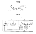
- FIG. 3 is a diagram illustrating part of the configuration of the second encoder 14.
- the pinion gear 17 includes a scissors gear mechanism, thereby eliminating backlash.
- a first gear 171 and a second gear 172 of the pinion gear 17 are biased in opposite directions from each other, whereby the pinion gear 17 meshes with the rack gear 16 in a state where backlash is eliminated.
- the rack gear 16 may include a scissors gear mechanism.
- FIG. 4 is a diagram illustrating a configuration of a robot system 1 according to the first embodiment.
- the robot control apparatus performs similar control to any actuator 10, so that, in this embodiment, an example of driving one actuator 10 is explained.
- a robot control apparatus 3 controls the actuator 10b based on the information obtained from the first and second encoders 13b and 14b.
- the robot control apparatus 3 drives the motor 11 provided in the joint of the robot 2. Consequently, the driving force of the motor 11 is transmitted to the link 26 by the speed reducer 12 and the link 26 is driven.
- the robot control apparatus 3 includes a command generating unit 20 that outputs a position command Pref of the motor 11 and a servo control unit 21 that controls the motor 11 so that the rotation angle of the motor 11 matches the position command Pref.
- the position command Pref is a position command defining the rotation angle of the motor 11.
- the command generating unit 20 outputs the position command Pref corrected based on rotation angles Pfb1 and Pfb2 obtained from the first and second encoders 13 and 14 to the servo control unit 21.
- the first encoder 13 detects the rotation angle of a rotation shaft 11a of the motor 11 as the rotation angle Pfb1 and the second encoder 14 detects the rotation angle of an output shaft 12a of the speed reducer 12 as the rotation angle Pfb2.
- the servo control unit 21 obtains the position command Pref from the command generating unit 20 and obtains the rotation angle Pfb1 of the motor 11 from the first encoder 13.
- the servo control unit 21 calculates a current command Eref for matching the rotation angle Pfb1 of the motor 11 and the position command Pref based on the position command Pref and the rotation angle Pfb1 and outputs the current command Eref to the motor 11.
- the position command Pref output from the command generating unit 20 is corrected based on the rotation angle Pfb1 of the motor 11 and the rotation angle Pfb2 of the output shaft 12a of the speed reducer 12. Because an element of delay time of servo control is not included in the rotation angle Pfb1 of the motor 11 and the rotation angle Pfb2 of the output shaft 12a of the speed reducer 12, torsion of the speed reducer 12 can be compensated without performing the setting operation of compensating for the delay time of servo control.
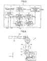
- FIG. 5 is a diagram illustrating the configuration of the command generating unit 20 according to the first embodiment.
- the command generating unit 20 includes a position command generating unit 30 and a position command correcting unit 31.
- the position command generating unit 30 generates a position command Pref0 of the motor 11 based on a predetermined command profile. Then, the position command generating unit 30 outputs the generated position command Pref0 to the position command correcting unit 31.
- the command profile is generated, for example, as follows. First, an end effector position command (XYZ coordinates) is calculated so that the trajectory of a not-shown end effector attached to the tip end of the link of the robot 2 passes at predetermined acceleration and speed.
- the XYZ coordinates are coordinates of space in which the end effector as a control point operates.
- the position command Pref0 (motor coordinates) of the motor 11 is generated by performing coordinate transformation on the end effector position command.
- the motor coordinates are coordinates of the rotation angle of the motor 11 that drives the link 26 of the robot 2.
- the command profile is formed by the position command Pref0 group generated according to the trajectory of the end effector.
- the position command correcting unit 31 generates a position compensation value Padd that is a position command correction signal and corrects the position command Pref0 output from the position command generating unit 30 by the position compensation value Padd.
- the position command correcting unit 31 includes a torsion position calculating unit 32, a torsion-position initial value storing unit 33, a torsion position difference calculating unit 34, a position compensation value calculating unit 35, a position compensation integrating unit 36, and a compensation position command calculating unit 37.
- the torsion position calculating unit 32 generates a torsion position Pdif based on the rotation angle Pfb1 of the rotation shaft 11a and the rotation angle Pfb2 of the output shaft 12a of the speed reducer 12 and outputs the generated torsion position Pdif to the torsion position difference calculating unit 34.
- the torsion position Pdif is information indicating torsion of the speed reducer 12.
- the torsion position calculating unit 32 subtracts the rotation angle Pfb1 of the motor 11 from the rotation angle Pfb2 calculated from the rotation angle Pfb2 of the output shaft 12a of the speed reducer 12 based on the reduction ratio and sets this difference value as the torsion position Pdif. For example, when the reduction ratio of the speed reducer 12 is set to n, the torsion position calculating unit 32 subtracts the rotation angle Pfb1 of the motor 11 from the rotation angle Pfb2 multiplied by n and sets this difference value as the torsion position Pdif.
- the torsion-position initial value storing unit 33 stores the torsion position Pdif output from the torsion position calculating unit 32 when an initialization signal Init is input, as a torsion position initial value Pdif0.
- the initialization signal Init is input to the torsion-position initial value storing unit 33, and the torsion position Pdif output from the torsion position calculating unit 32 at that time is stored as the torsion position initial value Pdif0 in the torsion-position initial value storing unit 33.
- the torsion position difference Perr is information indicating a displacement of the torsion position Pdif from the torsion position initial value Pdif0.
- the position compensation value calculating unit 35 subtracts a position compensation integrated value Padded from the torsion position difference Perr to generate the position compensation value Padd.
- the position compensation value Padd is a position command correction signal and is output from the position compensation value calculating unit 35 to the compensation position command calculating unit 37.
- the position compensation integrated value Padded is information output from the position compensation integrating unit 36 and the position compensation integrating unit 36 integrates the position compensation value Padd output from the position compensation value calculating unit 35 to generate the position compensation integrated value Padded.
- the compensation position command calculating unit 37 adds the position compensation value Padd obtained from the position compensation value calculating unit 35 to the position command Pref0 obtained from the position command generating unit 30 to generate a new position command Pref. Then, the compensation position command calculating unit 37 outputs the generated position command Pref to the servo control unit 21.
- the command generating unit 20 corrects the position command Pref0 by adding the position compensation value Padd obtained from the difference between the rotation angle Pfb1 of the motor 11 and the rotation angle Pfb2 of the output shaft 12a of the speed reducer 12 to the position command Pref0 as the position command correction signal.
- an element of delay time of servo control is included between the position command Pref0 and the rotation angle Pfb1 of the motor 11, an element of delay time of servo control is not included in the rotation angle Pfb1 of the motor 11 and the rotation angle Pfb2 of the output shaft 12a of the speed reducer 12. Therefore, in the robot system 1 according to the first embodiment, the position error due to the torsion of the speed reducer 12 can be reduced without performing the setting operation of compensating for delay time of servo control.
- the position compensation value calculating unit 35 because the position compensation integrated value Padded is subtracted from the torsion position difference Perr, the torsion position difference Perr once added as the position compensation value Padd is not added from the next time. Thus, the position command Pref can be accurately compensated according to the torsion position difference Perr.
- the second encoder 14 is provided to three shafts, however, because each shaft is independently controlled, the second encoder 14 may be provided to only one or two shafts as appropriate.
- a limiting unit such a limiter and a filter, may be provided for avoiding abrupt fluctuation of the position command Pref due to correction.
- the limiting unit can be provided in a path between the torsion position difference calculating unit 34 and the compensation position command calculating unit 37.
- the position compensation value Padd obtained by the compensation position command calculating unit 37 can be limited to a limiting value by providing a limiter between the position compensation value calculating unit 35 and the compensation position command calculating unit 37.
- the rate of change of the position compensation value Padd obtained by the compensation position command calculating unit 37 can be limited by providing a filter between the position compensation value calculating unit 35 and the compensation position command calculating unit 37.
- an encoder is explained as an example of the first detecting unit that detects the rotation angle Pfb1 of the motor 11, however, it is sufficient that the first detecting unit can detect the rotation angle Pfb1 of the motor 11.
- the first detecting unit may be an observer.
- an encoder is explained as an example of the second detecting unit that detects the rotation angle Pfb2 of the output shaft 12a of the speed reducer 12, however, it is sufficient that the second detecting unit can detect the rotation angle Pfb2 of the output shaft 12a of the speed reducer 12.
- the second detecting unit may be an observer.
- FIG. 6 is a schematic side view of a robot according to the second embodiment and FIG. 7 is a schematic cross-sectional view taken along line A-A in FIG. 6 .
- the configuration similar to the robot system 1 according to the first embodiment is explained by assigning the same reference numerals.
- a strain gauge unit 40a is attached to the lower arm 26b and a strain gauge unit 40b is attached to the upper arm 26c. Deflection of the lower arm 26b and the upper arm 26c can be accurately detected by attaching the strain gauge units 40a and 40b (an example of a third detector) to an area in which an amount of strain is large in the lower arm 26b and the upper arm 26c.
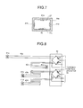
- the strain gauge unit 40a is attached to a rectangular inner wall 27 of the lower arm 26b. Specifically, each of strain gauges 41a to 41d configuring the strain gauge unit 40a is attached to a corresponding side of the inner wall 27 of the lower arm 26b, and a substrate 43 is attached to one side of the inner wall 27 of the lower arm 26b.
- strain gauges 41a to 41d a resistance value changes according to deflection of the lower arm 26b.
- the strain gauges 41a and 41c are strain gauges for detecting deflection in a first direction (vertical direction in FIG. 7 ) in deflection of the lower arm 26b and the strain gauges 41b and 41d are strain gauges for detecting deflection in a second direction (horizontal direction in FIG. 7 ), which is orthogonal to the first direction, in deflection of the lower arm 26b.
- the strain gauges 41a and 41c are connected to the substrate 43 via wires 42a and 42c, and are bridged with two resistors R on the substrate 43.
- the strain gauges 41b and 41d are connected to the substrate 43 via wires 42b and 42b and are bridged with two resistors R on the substrate 43.
- the wires 42a to 42d connecting the strain gauges 41a to 41d and the substrate 43 are formed to have the same length. Consequently, deflection of the lower arm 26b is accurately detected.
- a bridge connection structure with the resistors R may be provided for each of the strain gauges 41a to 41d.
- the strain gauge unit 40a detects deflection information in the first direction and the second direction of the lower arm 26b. Deflection of the lower arm 26b in the first direction can be compensated by adjusting the joint 29a and deflection of the lower arm 26b in the second direction can be compensated by adjusting the joint 29b.
- the strain gauge unit 40b has a configuration similar to the strain gauge unit 40a.
- a robot control apparatus 3A detects deflection of the lower arm 26b and the upper arm 26c in each direction based on the deflection information output from the strain gauge units 40a and 40b and corrects control of the motor 11 by transforming the amount of the deflection into motor coordinate values. Consequently, deflection of the lower arm 26b and the upper arm 26c is compensated.
- Deflection of the arms 26b and 26c may be digitalized on the substrate 43 of the strain gauge units 40a and 40b to output to the robot control apparatus 3A.
- the process can be simplified by daisy-chaining the strain gauge units 40a and 40b.
- the strain gauge unit 40b is connected to the strain gauge unit 40a and the strain gauge unit 40a is connected to the robot control apparatus 3A (see FIG. 9 ). Then, the strain gauge unit 40b outputs a detection result of the strain gauge unit 40b to the strain gauge unit 40a by a serial signal. Moreover, the strain gauge unit 40a transmits a detection result of the strain gauge unit 40a to the robot control apparatus 3A (see FIG. 9 ) by a serial signal together with the detection result by the strain gauge unit 40b.
- the strain gauge units 40a and 40b are generically referred to as a strain gauge unit 40 in some cases.
- FIG. 9 is a diagram illustrating the configuration of a robot system 1A according to the second embodiment.
- the robot control apparatus 3A according to the second embodiment controls one actuator 10 is explained.
- the robot control apparatus 3A controls the actuator 10b based on the information obtained from the first and second encoders 13b and 14b and the strain gauge unit 40a.
- the robot 2A includes the strain gauge unit 40.
- the strain gauge unit 40 outputs detected deflection information Pfc to the robot control apparatus 3A.
- the robot control apparatus 3A includes a command generating unit 20A and the servo control unit 21.
- the servo control unit 21 according to the second embodiment has a configuration similar to the servo control unit 21 according to the first embodiment.
- FIG. 10 is a diagram illustrating the configuration of the command generating unit 20A according to the second embodiment.
- the command generating unit 20A includes the position command generating unit 30 in the similar manner to the command generating unit 20 according to the first embodiment. Moreover, the command generating unit 20A includes a position command correcting unit 31A.
- the position command correcting unit 31A includes the torsion position calculating unit 32, the torsion-position initial value storing unit 33, the torsion position difference calculating unit 34, the position compensation value calculating unit 35, and the position compensation integrating unit 36 in the similar manner to the position command correcting unit 31 according to the first embodiment.
- the position command correcting unit 31A includes a deflection-amount inverse transform unit 51, a deflection-position initial value storing unit 52, a deflection position difference calculating unit 53, a position compensation value calculating unit 54, a position compensation integrating unit 55, and a compensation position command calculating unit 56.
- the deflection-amount inverse transform unit 51 calculates a deflection position Pdif2 according to the deflection information Pfc obtained from the strain gauge unit 40. Specifically, the deflection-amount inverse transform unit 51 detects an amount of deflection of the driving link 26 in a predetermined direction in the deflection information Pfc and performs coordinate transformation on the amount of deflection, thereby generating the deflection position Pdif2 (motor coordinates) of the link 26 driven by the motor 11.
- the motor coordinates are coordinates of the rotation angle of the motor 11 that drives the link 26 of the robot 2A.
- the deflection-amount inverse transform unit 51 generates the deflection position Pdif2 of the lower arm 26b driven by the motor 11 by performing coordinate transformation on an amount of deflection of the lower arm 26b in the second direction in the deflection information Pfc obtained from the strain gauge unit 40a.
- the deflection-position initial value storing unit 52 stores therein the deflection position Pdif2 output from the deflection-amount inverse transform unit 51 when an initialization signal Init is input, as a deflection position initial value Pdif3.
- the deflection position Pdif2 output from the deflection-amount inverse transform unit 51 is stored in the deflection-position initial value storing unit 52 as the deflection position initial value Pdif3.
- the deflection position difference Perr1 is information indicating a displacement of the deflection position Pdif2 from the deflection position initial value Pdif3.
- the position compensation value calculating unit 54 subtracts a position compensation integrated value Padded1 from the deflection position difference Perr1 and outputs the subtracted value to the compensation position command calculating unit 56 as a position compensation value Padd1.
- the position compensation integrated value Padded1 is information output from the position compensation integrating unit 55 and the position compensation integrating unit 55 integrates the position compensation value Padd1 output from the position compensation value calculating unit 54 to generate the position compensation integrated value Padded1.
- the compensation position command calculating unit 56 adds the position compensation value Padd obtained from the position compensation value calculating unit 35 and the position compensation value Padd1 obtained from the position compensation value calculating unit 54 to the position command Pref0 obtained from the position command generating unit 30 to generate a new position command Pref. Then, the compensation position command calculating unit 56 outputs the generated position command Pref to the servo control unit 21.
- the command generating unit 20A includes the position compensation value Padd calculated based on the rotation angle Pfd1 and Pfb2 and the position compensation value Padd1 calculated based on the deflection amount Pdif2 output from the deflection-amount inverse transform unit 51, to be added to the position command Pref0. Therefore, in addition to reducing the position error due to the torsion of the speed reducer 12, the position error due to the deflection of the link 26 can further be reduced.
- the position compensation value calculating unit 54 because the position compensation integrated value Padded1 is subtracted from the deflection position difference Perr1, the deflection position difference Perr1 once added as the position compensation value Padd1 is not added from the next time. Thus, the position command Pref can be accurately compensated according to the deflection position difference Perr1.
- the strain gauge is explained as an example of the detector that detects deflection of the link 26, however, for example, it is possible to use a piezoelectric strain sensor as the detector that detects deflection of the link 26.
- the position compensation value Padd obtained from the rotation angle Pfb1 of the motor 11 and the rotation angle Pfb2 of the output shaft 12a of the speed reducer 12 are added to the position command Pref0. Therefore, the position error due to the torsion of the speed reducer 12 can be reduced without performing the setting operation of compensating for delay time of servo control, so that highly accurate positioning can be performed.
Landscapes
- Engineering & Computer Science (AREA)
- Robotics (AREA)
- Mechanical Engineering (AREA)
- Manipulator (AREA)
- Numerical Control (AREA)
Abstract
Description
- The embodiments discussed herein are directed to a robot system, a robot control apparatus, and a robot control method.
- There has been known a robot control apparatus that controls a robot in which a plurality of links is connected by joints. The robot control apparatus controls a motor provided at a joint portion of the robot and transmits power of the motor to a link via a speed reducer.
- There is torsion in the speed reducer. Therefore, a robot control apparatus is proposed that improves a positioning accuracy by compensating for the torsion of the speed reducer. For example, the specification of
U.S. Patent Application Publication No. 2010/0191374 proposes a robot control apparatus that compensates for torsion of a speed reducer by correcting a position command based on a difference between the output of an encoder provided on the output shaft side of the speed reducer and a predetermined position command. - However, in the above-described conventional robot control apparatus, an element of control delay is present between the output of the encoder and the position command, so that the position command needs to be corrected by performing adjustment according to the control delay. The control delay time changes depending on the responsiveness of a robot. Therefore, the delay time needs to be set according to the responsiveness of a robot, so that if the accuracy of a setting value is low, positioning cannot be performed with a high accuracy.
- An object of an aspect of the embodiments is to provide a robot system, a robot control apparatus, and a robot control method capable of easily performing highly-accurate positioning.
- A robot system according to an aspect of embodiments includes a robot and a robot control apparatus. Adjacent links are connected via a joint in the robot and the robot includes a motor and a speed reducer, which transmits a driving force of the motor to the link, in the joint. The robot control apparatus controls the robot by driving the motor. The robot includes a first detecting unit that detects a rotation angle of the motor and a second detecting unit that detects a rotation angle of an output shaft of the speed reducer. The robot control apparatus includes a control unit that corrects a position command of the motor based on the rotation angle of the motor detected by the first detecting unit and the rotation angle of the output shaft of the speed reducer detected by the second detecting unit.
- According to an aspect of embodiments, it is possible to provide a robot system, a robot control apparatus, and a robot control method capable of easily performing highly-accurate positioning.
- A more complete appreciation of the invention and many of the attendant advantages thereof will be readily obtained as the same becomes better understood by reference to the following detailed description when considered in connection with the accompanying drawings, wherein:
-
FIG. 1 is a schematic side view of a robot according to a first embodiment; -
FIG. 2 is a schematic front view of the robot according to the first embodiment; -
FIG. 3 is a diagram illustrating part of a configuration of a second encoder; -
FIG. 4 is a diagram illustrating a configuration of a robot system according to the first embodiment; -
FIG. 5 is a diagram illustrating a configuration of a command generating unit according to the first embodiment; -
FIG. 6 is a schematic side view of a robot according to a second embodiment; -
FIG. 7 is a schematic cross-sectional view taken along line A-A inFIG. 6 ; -
FIG. 8 is a diagram illustrating a wiring state of strain gauges; -
FIG. 9 is a diagram illustrating a configuration of a robot system according to the second embodiment; and -
FIG. 10 is a diagram illustrating a configuration of a command generating unit according to the second embodiment. - Hereinafter, some embodiments of a robot system disclosed in the present application will be described in detail based on the drawings. The present invention is not limited to these embodiments.
- (First Embodiment)
The robot system according to the first embodiment includes a robot and a robot control apparatus. Adjacent links are connected to each other via a joint in the robot and the robot control apparatus controls the robot by driving the joint. A multi-joint robot is explained as an example of the robot, however, it is sufficient that the robot is a robot including at least one joint. As the links connected via the joint, a base, a swivel head, and an arm are exemplified, however, the links are not limited thereto. - First, the configuration of the robot according to the first embodiment is explained.
FIG. 1 is a schematic side view of the robot according to the first embodiment andFIG. 2 is a schematic front view of the robot according to the present embodiment. - As shown in
FIG. 1 and FIG. 2 , arobot 2 is a multi-joint robot that includes abase 25, aswivel head 26a, alower arm 26b, anupper arm 26c, andjoints 29a to 29c. The joint 29a rotatably connects theswivel head 26a to thebase 25. The joint 29b rotatably connects thelower arm 26b to theswivel head 26a. The joint 29c rotatably connects theupper arm 26c to thelower arm 26b. In the followings, each of thejoints 29a to 29c is generically referred to as a joint 29 and theswivel head 26a, thelower arm 26b, and theupper arm 26c are generically referred to as alink 26 in some cases for convenience' sake of explanation. - The
base 25 is fixed to a fixed surface, such as a floor and a ceiling, with not-shown anchor bolts. Thebase 25, theswivel head 26a, thelower arm 26b, and theupper arm 26c are, for example, structure support members made of a metal casting or the like and are arranged in order from thebase 25 via the joints 29. - The joint 29a includes an
actuator 10a, afirst encoder 13a, and asecond encoder 14a. In the similar manner, thejoint 29b includes anactuator 10b, afirst encoder 13b, and asecond encoder 14b and thejoint 29c includes anactuator 10c, afirst encoder 13c, and asecond encoder 14c. In the followings, theactuators 10a to 10c are generically referred to as anactuator 10 in some cases for convenience' sake of explanation. In the similar manner, thefirst encoders 13a to 13c (an example of a first detector) are generically referred to as afirst encoder 13 and thesecond encoders 14a to 14c (an example of a second detector) are generically referred to as asecond encoder 14 in some cases. - The
first encoder 13 is an encoder that detects the rotation angle of the input shaft of theactuator 10. Thesecond encoder 14 is an encoder that detects the rotation angle of the output shaft of theactuator 10. As described later, theactuator 10 includes a motor 11 (seeFIG. 4 ) and a speed reducer 12 (seeFIG. 4 ). The driving force of themotor 11 is transmitted to thelink 26 via thespeed reducer 12. Thefirst encoder 13 detects the rotation angle of themotor 11 and thesecond encoder 14 detects the rotation angle of the output shaft of thespeed reducer 12. - The
second encoders 14a to 14c each include arack gear 16, apinion gear 17 meshing with therack gear 16, and adetector 18. Thedetector 18 detects the rotation angle of the output shaft of thespeed reducer 12 according to an amount of rotation of thepinion gear 17. In thesecond encoder 14, the relative position of therack gear 16 and thepinion gear 17 changes with the rotation of the output shaft of thespeed reducer 12. -
FIG. 3 is a diagram illustrating part of the configuration of thesecond encoder 14. As shown inFIG. 3 , thepinion gear 17 includes a scissors gear mechanism, thereby eliminating backlash. In other words, afirst gear 171 and asecond gear 172 of thepinion gear 17 are biased in opposite directions from each other, whereby thepinion gear 17 meshes with therack gear 16 in a state where backlash is eliminated. In this embodiment, an example in which thepinion gear 17 includes a scissors gear mechanism is explained, however, therack gear 16 may include a scissors gear mechanism. - Next, the configuration and the operation of the robot control apparatus that controls the
robot 2 are explained.FIG. 4 is a diagram illustrating a configuration of arobot system 1 according to the first embodiment. The robot control apparatus performs similar control to anyactuator 10, so that, in this embodiment, an example of driving oneactuator 10 is explained. For example, in the case of controlling theactuator 10b, arobot control apparatus 3 controls theactuator 10b based on the information obtained from the first andsecond encoders - The
robot control apparatus 3 drives themotor 11 provided in the joint of therobot 2. Consequently, the driving force of themotor 11 is transmitted to thelink 26 by thespeed reducer 12 and thelink 26 is driven. As shown inFIG. 4 , therobot control apparatus 3 includes acommand generating unit 20 that outputs a position command Pref of themotor 11 and aservo control unit 21 that controls themotor 11 so that the rotation angle of themotor 11 matches the position command Pref. The position command Pref is a position command defining the rotation angle of themotor 11. - The
command generating unit 20 outputs the position command Pref corrected based on rotation angles Pfb1 and Pfb2 obtained from the first andsecond encoders servo control unit 21. Thefirst encoder 13 detects the rotation angle of arotation shaft 11a of themotor 11 as the rotation angle Pfb1 and thesecond encoder 14 detects the rotation angle of anoutput shaft 12a of thespeed reducer 12 as the rotation angle Pfb2. - The
servo control unit 21 obtains the position command Pref from thecommand generating unit 20 and obtains the rotation angle Pfb1 of themotor 11 from thefirst encoder 13. Theservo control unit 21 calculates a current command Eref for matching the rotation angle Pfb1 of themotor 11 and the position command Pref based on the position command Pref and the rotation angle Pfb1 and outputs the current command Eref to themotor 11. - As above, the position command Pref output from the
command generating unit 20 is corrected based on the rotation angle Pfb1 of themotor 11 and the rotation angle Pfb2 of theoutput shaft 12a of thespeed reducer 12. Because an element of delay time of servo control is not included in the rotation angle Pfb1 of themotor 11 and the rotation angle Pfb2 of theoutput shaft 12a of thespeed reducer 12, torsion of thespeed reducer 12 can be compensated without performing the setting operation of compensating for the delay time of servo control. -
FIG. 5 is a diagram illustrating the configuration of thecommand generating unit 20 according to the first embodiment. As shown inFIG. 5 , thecommand generating unit 20 includes a positioncommand generating unit 30 and a positioncommand correcting unit 31. - The position
command generating unit 30 generates a position command Pref0 of themotor 11 based on a predetermined command profile. Then, the positioncommand generating unit 30 outputs the generated position command Pref0 to the positioncommand correcting unit 31. - The command profile is generated, for example, as follows. First, an end effector position command (XYZ coordinates) is calculated so that the trajectory of a not-shown end effector attached to the tip end of the link of the
robot 2 passes at predetermined acceleration and speed. The XYZ coordinates are coordinates of space in which the end effector as a control point operates. Then, the position command Pref0 (motor coordinates) of themotor 11 is generated by performing coordinate transformation on the end effector position command. The motor coordinates are coordinates of the rotation angle of themotor 11 that drives thelink 26 of therobot 2. The command profile is formed by the position command Pref0 group generated according to the trajectory of the end effector. - The position
command correcting unit 31 generates a position compensation value Padd that is a position command correction signal and corrects the position command Pref0 output from the positioncommand generating unit 30 by the position compensation value Padd. Specifically, the positioncommand correcting unit 31 includes a torsionposition calculating unit 32, a torsion-position initialvalue storing unit 33, a torsion positiondifference calculating unit 34, a position compensationvalue calculating unit 35, a positioncompensation integrating unit 36, and a compensation positioncommand calculating unit 37. - The torsion
position calculating unit 32 generates a torsion position Pdif based on the rotation angle Pfb1 of therotation shaft 11a and the rotation angle Pfb2 of theoutput shaft 12a of thespeed reducer 12 and outputs the generated torsion position Pdif to the torsion positiondifference calculating unit 34. The torsion position Pdif is information indicating torsion of thespeed reducer 12. - Specifically, the torsion
position calculating unit 32 subtracts the rotation angle Pfb1 of themotor 11 from the rotation angle Pfb2 calculated from the rotation angle Pfb2 of theoutput shaft 12a of thespeed reducer 12 based on the reduction ratio and sets this difference value as the torsion position Pdif. For example, when the reduction ratio of thespeed reducer 12 is set to n, the torsionposition calculating unit 32 subtracts the rotation angle Pfb1 of themotor 11 from the rotation angle Pfb2 multiplied by n and sets this difference value as the torsion position Pdif. - The torsion-position initial
value storing unit 33 stores the torsion position Pdif output from the torsionposition calculating unit 32 when an initialization signal Init is input, as a torsion position initial value Pdif0. For example, when the posture of therobot 2 is a basic posture, the initialization signal Init is input to the torsion-position initialvalue storing unit 33, and the torsion position Pdif output from the torsionposition calculating unit 32 at that time is stored as the torsion position initial value Pdif0 in the torsion-position initialvalue storing unit 33. - The torsion position
difference calculating unit 34 subtracts the torsion position initial value Pdif0 obtained from the torsion-position initialvalue storing unit 33 from the torsion position Pdif obtained from the torsionposition calculating unit 32 to generate a torsion position difference Perr (=Pdif-Pdif0) . The torsion position difference Perr is information indicating a displacement of the torsion position Pdif from the torsion position initial value Pdif0. - The position compensation
value calculating unit 35 subtracts a position compensation integrated value Padded from the torsion position difference Perr to generate the position compensation value Padd. The position compensation value Padd is a position command correction signal and is output from the position compensationvalue calculating unit 35 to the compensation positioncommand calculating unit 37. The position compensation integrated value Padded is information output from the positioncompensation integrating unit 36 and the positioncompensation integrating unit 36 integrates the position compensation value Padd output from the position compensationvalue calculating unit 35 to generate the position compensation integrated value Padded. - The compensation position
command calculating unit 37 adds the position compensation value Padd obtained from the position compensationvalue calculating unit 35 to the position command Pref0 obtained from the positioncommand generating unit 30 to generate a new position command Pref. Then, the compensation positioncommand calculating unit 37 outputs the generated position command Pref to theservo control unit 21. - In this manner, in the
robot system 1 according to the first embodiment, thecommand generating unit 20 corrects the position command Pref0 by adding the position compensation value Padd obtained from the difference between the rotation angle Pfb1 of themotor 11 and the rotation angle Pfb2 of theoutput shaft 12a of thespeed reducer 12 to the position command Pref0 as the position command correction signal. Although an element of delay time of servo control is included between the position command Pref0 and the rotation angle Pfb1 of themotor 11, an element of delay time of servo control is not included in the rotation angle Pfb1 of themotor 11 and the rotation angle Pfb2 of theoutput shaft 12a of thespeed reducer 12. Therefore, in therobot system 1 according to the first embodiment, the position error due to the torsion of thespeed reducer 12 can be reduced without performing the setting operation of compensating for delay time of servo control. - Moreover, in the position compensation
value calculating unit 35, because the position compensation integrated value Padded is subtracted from the torsion position difference Perr, the torsion position difference Perr once added as the position compensation value Padd is not added from the next time. Thus, the position command Pref can be accurately compensated according to the torsion position difference Perr. - In the above embodiment, the
second encoder 14 is provided to three shafts, however, because each shaft is independently controlled, thesecond encoder 14 may be provided to only one or two shafts as appropriate. - A limiting unit, such a limiter and a filter, may be provided for avoiding abrupt fluctuation of the position command Pref due to correction. In this case, the limiting unit can be provided in a path between the torsion position
difference calculating unit 34 and the compensation
positioncommand calculating unit 37. - For example, the position compensation value Padd obtained by the compensation position
command calculating unit 37 can be limited to a limiting value by providing a limiter between the position compensationvalue calculating unit 35 and the compensation positioncommand calculating unit 37. Moreover, for example, the rate of change of the position compensation value Padd obtained by the compensation positioncommand calculating unit 37 can be limited by providing a filter between the position compensationvalue calculating unit 35 and the compensation positioncommand calculating unit 37. - Moreover, an encoder is explained as an example of the first detecting unit that detects the rotation angle Pfb1 of the
motor 11, however, it is sufficient that the first detecting unit can detect the rotation angle Pfb1 of themotor 11. For example, the first detecting unit may be an observer. In the similar manner, an encoder is explained as an example of the second detecting unit that detects the rotation angle Pfb2 of theoutput shaft 12a of thespeed reducer 12, however, it is sufficient that the second detecting unit can detect the rotation angle Pfb2 of theoutput shaft 12a of thespeed reducer 12. For example, the second detecting unit may be an observer. - (Second Embodiment)
Next, a robot system according to the second embodiment is explained. The robot system according to the second embodiment controls theactuator 10 by further compensating deflection of a link compared with the robot system according to the first embodiment. Consequently, even in the case where the link itself is deflected, for example, due to the own weight of the link, the force applied to an end effector at the link tip end, or the like, positioning of a robot can be accurately performed.FIG. 6 is a schematic side view of a robot according to the second embodiment andFIG. 7 is a schematic cross-sectional view taken along line A-A inFIG. 6 . The configuration similar to therobot system 1 according to the first embodiment is explained by assigning the same reference numerals. - As shown in
FIG. 6 , in arobot 2A according to the second embodiment, in addition to the configuration of therobot 2 according to the first embodiment, astrain gauge unit 40a is attached to thelower arm 26b and astrain gauge unit 40b is attached to theupper arm 26c. Deflection of thelower arm 26b and theupper arm 26c can be accurately detected by attaching thestrain gauge units lower arm 26b and theupper arm 26c. - As shown in
FIG. 7 , thestrain gauge unit 40a is attached to a rectangularinner wall 27 of thelower arm 26b. Specifically, each ofstrain gauges 41a to 41d configuring thestrain gauge unit 40a is attached to a corresponding side of theinner wall 27 of thelower arm 26b, and asubstrate 43 is attached to one side of theinner wall 27 of thelower arm 26b. - In the
strain gauges 41a to 41d, a resistance value changes according to deflection of thelower arm 26b. The strain gauges 41a and 41c are strain gauges for detecting deflection in a first direction (vertical direction inFIG. 7 ) in deflection of thelower arm 26b and the strain gauges 41b and 41d are strain gauges for detecting deflection in a second direction (horizontal direction inFIG. 7 ), which is orthogonal to the first direction, in deflection of thelower arm 26b. - As shown in
FIG. 8 , thestrain gauges substrate 43 viawires substrate 43. In the similar manner, the strain gauges 41b and 41d are connected to thesubstrate 43 viawires substrate 43. Thewires 42a to 42d connecting thestrain gauges 41a to 41d and thesubstrate 43 are formed to have the same length. Consequently, deflection of thelower arm 26b is accurately detected. A bridge connection structure with the resistors R may be provided for each of thestrain gauges 41a to 41d. - In this manner, the
strain gauge unit 40a detects deflection information in the first direction and the second direction of thelower arm 26b. Deflection of thelower arm 26b in the first direction can be compensated by adjusting the joint 29a and deflection of thelower arm 26b in the second direction can be compensated by adjusting the joint 29b. Thestrain gauge unit 40b has a configuration similar to thestrain gauge unit 40a. - A
robot control apparatus 3A detects deflection of thelower arm 26b and theupper arm 26c in each direction based on the deflection information output from thestrain gauge units motor 11 by transforming the amount of the deflection into motor coordinate values. Consequently, deflection of thelower arm 26b and theupper arm 26c is compensated. - Deflection of the
arms substrate 43 of thestrain gauge units robot control apparatus 3A. In this case, the process can be simplified by daisy-chaining thestrain gauge units - For example, the
strain gauge unit 40b is connected to thestrain gauge unit 40a and thestrain gauge unit 40a is connected to therobot control apparatus 3A (seeFIG. 9 ). Then, thestrain gauge unit 40b outputs a detection result of thestrain gauge unit 40b to thestrain gauge unit 40a by a serial signal. Moreover, thestrain gauge unit 40a transmits a detection result of thestrain gauge unit 40a to therobot control apparatus 3A (seeFIG. 9 ) by a serial signal together with the detection result by thestrain gauge unit 40b. In the followings, for the convenience' sake of explanation, thestrain gauge units strain gauge unit 40 in some cases. - Next, the configuration and the operation of the robot control apparatus that controls the
robot 2A according to the second embodiment are explained.FIG. 9 is a diagram illustrating the configuration of arobot system 1A according to the second embodiment. In this embodiment, for easy understanding of the explanation, an example in which therobot control apparatus 3A according to the second embodiment controls oneactuator 10 is explained. For example, in the case of controlling theactuator 10b, therobot control apparatus 3A controls theactuator 10b based on the information obtained from the first andsecond encoders strain gauge unit 40a. - As described above, the
robot 2A includes thestrain gauge unit 40. Thestrain gauge unit 40 outputs detected deflection information Pfc to therobot control apparatus 3A. - The
robot control apparatus 3A includes acommand generating unit 20A and theservo control unit 21. Theservo control unit 21 according to the second embodiment has a configuration similar to theservo control unit 21 according to the first embodiment. - The position command Pref output from the
command generating unit 20A is corrected based on the deflection information Pfc in addition to the rotation angles Pfb1 and Pfb2. Therefore, torsion of thespeed reducer 12 is compensated and moreover strain of thelink 26 can be compensated.FIG. 10 is a diagram illustrating the configuration of thecommand generating unit 20A according to the second embodiment. - As shown in
FIG. 10 , thecommand generating unit 20A includes the positioncommand generating unit 30 in the similar manner to thecommand generating unit 20 according to the first embodiment. Moreover, thecommand generating unit 20A includes a positioncommand correcting unit 31A. The positioncommand correcting unit 31A includes the torsionposition calculating unit 32, the torsion-position initialvalue storing unit 33, the torsion positiondifference calculating unit 34, the position compensationvalue calculating unit 35, and the positioncompensation integrating unit 36 in the similar manner to the positioncommand correcting unit 31 according to the first embodiment. - Furthermore, the position
command correcting unit 31A includes a deflection-amountinverse transform unit 51, a deflection-position initialvalue storing unit 52, a deflection positiondifference calculating unit 53, a position compensationvalue calculating unit 54, a positioncompensation integrating unit 55, and a compensation positioncommand calculating unit 56. - The deflection-amount
inverse transform unit 51 calculates a deflection position Pdif2 according to the deflection information Pfc obtained from thestrain gauge unit 40. Specifically, the deflection-amountinverse transform unit 51 detects an amount of deflection of the drivinglink 26 in a predetermined direction in the deflection information Pfc and performs coordinate transformation on the amount of deflection, thereby generating the deflection position Pdif2 (motor coordinates) of thelink 26 driven by themotor 11. The motor coordinates are coordinates of the rotation angle of themotor 11 that drives thelink 26 of therobot 2A. - For example, in the control to the
actuator 10b that drives thelower arm 26b, the deflection-amountinverse transform unit 51 generates the deflection position Pdif2 of thelower arm 26b driven by themotor 11 by performing coordinate transformation on an amount of deflection of thelower arm 26b in the second direction in the deflection information Pfc obtained from thestrain gauge unit 40a. - The deflection-position initial
value storing unit 52 stores therein the deflection position Pdif2 output from the deflection-amountinverse transform unit 51 when an initialization signal Init is input, as a deflection position initial value Pdif3. For example, when the initialization signal Init is input to the deflection-position initialvalue storing unit 52 in a state where the posture of therobot 2A is a basic posture, the deflection position Pdif2 output from the deflection-amountinverse transform unit 51 is stored in the deflection-position initialvalue storing unit 52 as the deflection position initial value Pdif3. - The deflection position
difference calculating unit 53 subtracts the deflection position initial value Pdif3 obtained from the deflection-position initialvalue storing unit 52 from the deflection position Pdif2 obtained from the deflection-amountinverse transform unit 51 to generate a deflection position difference Perr1 (=Pdif2-Pdif3). The deflection position difference Perr1 is information indicating a displacement of the deflection position Pdif2 from the deflection position initial value Pdif3. - The position compensation
value calculating unit 54 subtracts a position compensation integrated value Padded1 from the deflection position difference Perr1 and outputs the subtracted value to the compensation positioncommand calculating unit 56 as a position compensation value Padd1. The position compensation integrated value Padded1 is information output from the positioncompensation integrating unit 55 and the positioncompensation integrating unit 55 integrates the position compensation value Padd1 output from the position compensationvalue calculating unit 54 to generate the position compensation integrated value Padded1. - The compensation position
command calculating unit 56 adds the position compensation value Padd obtained from the position compensationvalue calculating unit 35 and the position compensation value Padd1 obtained from the position compensationvalue calculating unit 54 to the position command Pref0 obtained from the positioncommand generating unit 30 to generate a new position command Pref. Then, the compensation positioncommand calculating unit 56 outputs the generated position command Pref to theservo control unit 21. - In this manner, in the
robot system 1A according to the second embodiment, thecommand generating unit 20A includes the position compensation value Padd calculated based on the rotation angle Pfd1 and Pfb2 and the position compensation value Padd1 calculated based on the deflection amount Pdif2 output from the deflection-amountinverse transform unit 51, to be added to the position command Pref0. Therefore, in addition to reducing the position error due to the torsion of thespeed reducer 12, the position error due to the deflection of thelink 26 can further be reduced. - In this manner, because the position error due to the deflection of the
link 26 can be reduced, for example, even when thelink 26 is deflected due to the own weight of thelink 26, a force applied to an end effector, or the like, positioning of therobot 2A can be accurately performed. - Moreover, in the position compensation
value calculating unit 54, because the position compensation integrated value Padded1 is subtracted from the deflection position difference Perr1, the deflection position difference Perr1 once added as the position compensation value Padd1 is not added from the next time. Thus, the position command Pref can be accurately compensated according to the deflection position difference Perr1. - In the above, the strain gauge is explained as an example of the detector that detects deflection of the
link 26, however, for example, it is possible to use a piezoelectric strain sensor as the detector that detects deflection of thelink 26. - As above, in the
robot systems motor 11 and the rotation angle Pfb2 of theoutput shaft 12a of thespeed reducer 12 are added to the position command Pref0. Therefore, the position error due to the torsion of thespeed reducer 12 can be reduced without performing the setting operation of compensating for delay time of servo control, so that highly accurate positioning can be performed.
Claims (6)
- A robot system (1, 1A) comprising:a robot (2, 2A), in which adjacent links (26a to 26c) are connected via a joint (29a to 29c), and a motor (11) and a speed reducer (12), which transmits a driving force of the motor (11) to the link (26a to 26c), are provided in the joint (29a to 29c); anda robot control apparatus (3, 3A) that controls the robot (2, 2A) by driving the motor (11), whereinthe robot (2, 2A) includes
a first detecting unit (13a to 13c) that detects a rotation angle of the motor (11), and
a second detecting unit (14a to 14c) that detects a rotation angle of an output shaft (12a) of the speed reducer (12), andthe robot control apparatus (3, 3A) includes a command generating unit (20) that corrects a position command of the motor (11) based on a detection result by the first detecting unit (13a to 13c) and a detection result by the second detecting unit (14a to 14c). - The robot system (1, 1A) according to claim 1, wherein the command generating unit (20) corrects the position command according to a difference between the detection result by the first detecting unit (13a to 13c) and the detection result by the second detecting unit (14a to 14c).
- The robot system (1, 1A) according to claim 1 or 2, wherein
the second detecting unit (14a to 14c) includes
a rack gear (16),
a pinion gear (17) that meshes with the rack gear (16) and changes a relative position with respect to the rack gear (16) along with a rotation of the output shaft (12a) of the speed reducer (12), and
a detector (18) that detects a rotation position of the output shaft (12a) of the speed reducer (12) according to an amount of rotation of the pinion gear (17), and
the rack gear (16) or the pinion gear (17) is a scissors gear. - The robot system (1A) according to any one of claims 1 to 3, further comprising a third detecting unit (40a, 40b) that detects a deflection of the link (26a to 26c), wherein
the command generating unit (20) corrects the position command based on a detection result by the third detecting unit (40a, 40b) in addition to the detection result by the first detecting unit (13a to 13c) and the detection result by the second detecting unit (14a to 14c). - A robot control apparatus (3, 3A) comprising:a position command generating unit (20) that generates a position command defining a position of a robot (2, 2A) including a plurality of links (26a to 26c); anda position command correcting unit (31, 31A) that corrects a position command of the motor (11) based on a rotation angle of the motor (11), which drives the link (26a to 26c) of the robot (2, 2A) via a speed reducer (12), and a rotation angle of an output shaft (12a) of the speed reducer (12).
- A robot control method comprising:detecting a rotation angle of the motor (11) that drives a link (26a to 26c) of a robot (2, 2A) via a speed reducer (12);detecting a rotation angle of an output shaft (12a) of the speed reducer (12); andcorrecting a position command of the motor (11) based on a detection result of a rotation angle of the motor (11) and a detection result of a rotation angle of the output shaft (12a).
Applications Claiming Priority (1)
| Application Number | Priority Date | Filing Date | Title |
|---|---|---|---|
| JP2011037454A JP5370392B2 (en) | 2011-02-23 | 2011-02-23 | Robot system, robot control apparatus, and robot control method |
Publications (2)
| Publication Number | Publication Date |
|---|---|
| EP2492061A1 true EP2492061A1 (en) | 2012-08-29 |
| EP2492061B1 EP2492061B1 (en) | 2015-09-30 |
Family
ID=45524275
Family Applications (1)
| Application Number | Title | Priority Date | Filing Date |
|---|---|---|---|
| EP11195730.4A Not-in-force EP2492061B1 (en) | 2011-02-23 | 2011-12-27 | Robot System, Robot Control Apparatus, and Robot Control Method |
Country Status (4)
| Country | Link |
|---|---|
| US (1) | US8849455B2 (en) |
| EP (1) | EP2492061B1 (en) |
| JP (1) | JP5370392B2 (en) |
| CN (1) | CN102649270B (en) |
Families Citing this family (22)
| Publication number | Priority date | Publication date | Assignee | Title |
|---|---|---|---|---|
| JP5821210B2 (en) * | 2011-02-22 | 2015-11-24 | セイコーエプソン株式会社 | Horizontal articulated robot and control method of horizontal articulated robot |
| JP5488494B2 (en) * | 2011-02-23 | 2014-05-14 | 株式会社安川電機 | Robot system |
| JP6053424B2 (en) * | 2012-09-25 | 2016-12-27 | キヤノン株式会社 | Robot apparatus, robot control method, program, and recording medium |
| JP5628940B2 (en) * | 2013-01-11 | 2014-11-19 | ファナック株式会社 | Motor controller for correcting backlash |
| JP6164948B2 (en) * | 2013-06-20 | 2017-07-19 | キヤノン株式会社 | Robot apparatus and component manufacturing method |
| JP6097174B2 (en) * | 2013-08-05 | 2017-03-15 | 株式会社東芝 | Robot controller |
| JP6374274B2 (en) * | 2014-09-04 | 2018-08-15 | 国立大学法人長岡技術科学大学 | Control device and reduction gear system |
| DE102015106389B4 (en) * | 2015-04-24 | 2016-11-10 | Otto Bock Healthcare Products Gmbh | Method for controlling an artificial knee joint |
| JP6672637B2 (en) * | 2015-08-24 | 2020-03-25 | 株式会社デンソーウェーブ | Sensor position determination method, robot |
| JP6433420B2 (en) * | 2015-12-25 | 2018-12-05 | 本田技研工業株式会社 | Torque sensor terminal block structure |
| JP6831208B2 (en) * | 2015-12-25 | 2021-02-17 | 株式会社ダイヘン | Robot control device |
| US10613113B2 (en) * | 2016-06-27 | 2020-04-07 | Smc Corporation | Position detecting device |
| FR3054158B1 (en) * | 2016-07-21 | 2019-06-28 | Comau France | MACHINE-TOOL MACHINING |
| CN107872177A (en) * | 2016-09-23 | 2018-04-03 | 江苏科技大学 | A kind of permagnetic synchronous motor multi sensor combination full closed loop control method |
| JP6374471B2 (en) * | 2016-11-28 | 2018-08-15 | ファナック株式会社 | Bond structure |
| JP2018202589A (en) * | 2017-06-09 | 2018-12-27 | セイコーエプソン株式会社 | Control device, robot, and robot system |
| US10384707B2 (en) * | 2017-06-22 | 2019-08-20 | Robotelf Technology Co., Ltd. | Robot swing structure |
| CN112805536A (en) * | 2018-09-24 | 2021-05-14 | 株式会社尼康 | Encoder, drive device, robot device, control system, and control method thereof |
| JP7305951B2 (en) * | 2018-12-14 | 2023-07-11 | ニデック株式会社 | CALIBRATION DEVICE AND CALIBRATION METHOD |
| WO2022025072A1 (en) * | 2020-07-31 | 2022-02-03 | ファナック株式会社 | Control device and robot system |
| US20230400384A1 (en) * | 2020-11-12 | 2023-12-14 | Fanuc Corporation | Abnormality detection device which detects abnormalities in power transmission mechanism for transmitting rotational force outputted by motor |
| JP2022096193A (en) | 2020-12-17 | 2022-06-29 | 日本電産サンキョー株式会社 | Industrial robot |
Citations (5)
| Publication number | Priority date | Publication date | Assignee | Title |
|---|---|---|---|---|
| US4608651A (en) * | 1982-10-28 | 1986-08-26 | Kabushiki Kaisha Kobe Seiko Sho | Control system for direct teaching/playback type robots |
| US6258007B1 (en) * | 1999-05-27 | 2001-07-10 | Teijin Seiki Boston, Inc | Multi-sensor harmonic drive actuator arrangement assembly |
| US20090146650A1 (en) * | 2007-12-11 | 2009-06-11 | Nippon Soken, Inc. | Rotation angle sensor and scissors gear suitable therefor |
| US20100191374A1 (en) | 2009-01-27 | 2010-07-29 | Jason Tsai | Secondary position feedback control of a robot |
| US20110017003A1 (en) * | 2009-07-23 | 2011-01-27 | Canon Kabushiki Kaisha | Driving device and image forming apparatus |
Family Cites Families (19)
| Publication number | Priority date | Publication date | Assignee | Title |
|---|---|---|---|---|
| JPS5979312A (en) * | 1982-10-28 | 1984-05-08 | Kobe Steel Ltd | Controlling device of direct teaching type industrial robot |
| JPH0727410B2 (en) * | 1983-09-27 | 1995-03-29 | 株式会社神戸製鋼所 | Direct teaching type industrial robot controller |
| JPS61153702A (en) * | 1984-12-27 | 1986-07-12 | Hitachi Constr Mach Co Ltd | Soft structure work machine |
| JPH05216504A (en) * | 1992-02-06 | 1993-08-27 | Fanuc Ltd | Adaptive sliding mode control system for control object including spring system |
| US5455497A (en) * | 1992-04-20 | 1995-10-03 | Honda Giken Kogyo Kabushiki Kaisha | Legged mobile robot and a system for controlling the same |
| US5459925A (en) * | 1993-02-24 | 1995-10-24 | Fanuc Robotics North America, Inc. | Planetary type speed reducer having compound planets and method of constructing such planets |
| JPH0727410A (en) | 1993-07-12 | 1995-01-27 | Daikin Ind Ltd | Air conditioner outlet structure |
| JPH08150580A (en) * | 1994-11-29 | 1996-06-11 | Toshiba Corp | Industrial robot |
| JPH09267289A (en) * | 1996-03-29 | 1997-10-14 | Mitsubishi Electric Corp | Industrial robot |
| JP3674778B2 (en) * | 2001-09-27 | 2005-07-20 | 本田技研工業株式会社 | Leg joint assist device for legged mobile robot |
| JP3665013B2 (en) * | 2001-11-09 | 2005-06-29 | 本田技研工業株式会社 | Leg joint assist device for legged mobile robot |
| JP2003291082A (en) * | 2002-04-01 | 2003-10-14 | Sharp Corp | Articulated leg control device |
| JP3738759B2 (en) * | 2002-11-05 | 2006-01-25 | 株式会社安川電機 | Absolute position accuracy improvement device for industrial robots |
| JP4192780B2 (en) * | 2003-12-26 | 2008-12-10 | 株式会社安川電機 | Robot control device |
| JP2007185743A (en) * | 2006-01-13 | 2007-07-26 | Tietech Co Ltd | Robot device |
| JP5400473B2 (en) * | 2009-05-22 | 2014-01-29 | 川崎重工業株式会社 | Robot equipment |
| CN201522262U (en) * | 2009-09-29 | 2010-07-07 | 济南沃茨数控机械有限公司 | Automatic compensation measuring device |
| JP2011209099A (en) * | 2010-03-30 | 2011-10-20 | Sony Corp | Torque sensor and robot apparatus |
| JP5488494B2 (en) * | 2011-02-23 | 2014-05-14 | 株式会社安川電機 | Robot system |
-
2011
- 2011-02-23 JP JP2011037454A patent/JP5370392B2/en not_active Expired - Fee Related
- 2011-12-21 US US13/333,858 patent/US8849455B2/en not_active Expired - Fee Related
- 2011-12-27 EP EP11195730.4A patent/EP2492061B1/en not_active Not-in-force
- 2011-12-30 CN CN201110456595.8A patent/CN102649270B/en not_active Expired - Fee Related
Patent Citations (5)
| Publication number | Priority date | Publication date | Assignee | Title |
|---|---|---|---|---|
| US4608651A (en) * | 1982-10-28 | 1986-08-26 | Kabushiki Kaisha Kobe Seiko Sho | Control system for direct teaching/playback type robots |
| US6258007B1 (en) * | 1999-05-27 | 2001-07-10 | Teijin Seiki Boston, Inc | Multi-sensor harmonic drive actuator arrangement assembly |
| US20090146650A1 (en) * | 2007-12-11 | 2009-06-11 | Nippon Soken, Inc. | Rotation angle sensor and scissors gear suitable therefor |
| US20100191374A1 (en) | 2009-01-27 | 2010-07-29 | Jason Tsai | Secondary position feedback control of a robot |
| US20110017003A1 (en) * | 2009-07-23 | 2011-01-27 | Canon Kabushiki Kaisha | Driving device and image forming apparatus |
Non-Patent Citations (1)
| Title |
|---|
| JUAN FERNANDO PEZA SOLIS, GERARDO SILVA NAVARRO, RAFAEL CASTRO LINARES: "Modeling and Tip Position Control of a Flexible Link Robot", COMPUTACIÓN Y SISTEMAS, vol. 12, no. 4, 2009, pages 421 - 435, XP002675738, ISSN: 1405-5546, Retrieved from the Internet <URL:http://www.cic.ipn.mx/sitioCIC/images/revista/vol12-04/v12no4_art04.pdf> [retrieved on 20120509] * |
Also Published As
| Publication number | Publication date |
|---|---|
| CN102649270B (en) | 2016-05-18 |
| US20120215353A1 (en) | 2012-08-23 |
| CN102649270A (en) | 2012-08-29 |
| JP2012171069A (en) | 2012-09-10 |
| US8849455B2 (en) | 2014-09-30 |
| EP2492061B1 (en) | 2015-09-30 |
| JP5370392B2 (en) | 2013-12-18 |
Similar Documents
| Publication | Publication Date | Title |
|---|---|---|
| US8849455B2 (en) | Robot system and robot control apparatus | |
| US11090805B2 (en) | Robot | |
| US9844875B2 (en) | Robot | |
| US9120228B2 (en) | Method of controlling robot and robot | |
| CN104379308B (en) | Robot controller and robot control method | |
| JP6700669B2 (en) | Control method, robot device, program, recording medium, and article manufacturing method | |
| US9452529B2 (en) | Robot, robot control device, and robot system | |
| JP7227073B2 (en) | Workpiece rotating device and robot system | |
| JPWO2006022201A1 (en) | Robot evaluation system and evaluation method | |
| CN110871456B (en) | Robot | |
| JP2013000833A (en) | Method of detecting failure of robot, and robot | |
| JP6398204B2 (en) | Positioning accuracy correction method for robot apparatus | |
| US20150266185A1 (en) | Robot and robot system | |
| JP2023515598A (en) | robot device | |
| US11141855B2 (en) | Robot system, method of controlling robot arm, recording medium, and method of manufacturing an article | |
| JP6485620B2 (en) | Robot control system and robot control method | |
| WO2019012942A1 (en) | Robot controller | |
| JP2013094934A (en) | Robot | |
| JP6943906B2 (en) | robot | |
| US20240383142A1 (en) | Robot system with stored position information of sensor | |
| JP5856837B2 (en) | Robot teaching point creation method and robot system | |
| JP3671694B2 (en) | Robot teaching method and apparatus | |
| CN121548486A (en) | Control device, parameter calibration method and procedure | |
| JP5381039B2 (en) | Articulated manipulator tip position control method and articulated manipulator | |
| CN106476008B (en) | Robot control device |
Legal Events
| Date | Code | Title | Description |
|---|---|---|---|
| PUAI | Public reference made under article 153(3) epc to a published international application that has entered the european phase |
Free format text: ORIGINAL CODE: 0009012 |
|
| AK | Designated contracting states |
Kind code of ref document: A1 Designated state(s): AL AT BE BG CH CY CZ DE DK EE ES FI FR GB GR HR HU IE IS IT LI LT LU LV MC MK MT NL NO PL PT RO RS SE SI SK SM TR |
|
| AX | Request for extension of the european patent |
Extension state: BA ME |
|
| 17P | Request for examination filed |
Effective date: 20120928 |
|
| GRAP | Despatch of communication of intention to grant a patent |
Free format text: ORIGINAL CODE: EPIDOSNIGR1 |
|
| INTG | Intention to grant announced |
Effective date: 20150528 |
|
| RIN1 | Information on inventor provided before grant (corrected) |
Inventor name: IZUMI, TETSURO Inventor name: MATSUO, TOMOHIRO |
|
| GRAS | Grant fee paid |
Free format text: ORIGINAL CODE: EPIDOSNIGR3 |
|
| GRAA | (expected) grant |
Free format text: ORIGINAL CODE: 0009210 |
|
| AK | Designated contracting states |
Kind code of ref document: B1 Designated state(s): AL AT BE BG CH CY CZ DE DK EE ES FI FR GB GR HR HU IE IS IT LI LT LU LV MC MK MT NL NO PL PT RO RS SE SI SK SM TR |
|
| REG | Reference to a national code |
Ref country code: CH Ref legal event code: EP Ref country code: GB Ref legal event code: FG4D |
|
| REG | Reference to a national code |
Ref country code: AT Ref legal event code: REF Ref document number: 752113 Country of ref document: AT Kind code of ref document: T Effective date: 20151015 |
|
| REG | Reference to a national code |
Ref country code: IE Ref legal event code: FG4D |
|
| REG | Reference to a national code |
Ref country code: DE Ref legal event code: R096 Ref document number: 602011020149 Country of ref document: DE |
|
| PG25 | Lapsed in a contracting state [announced via postgrant information from national office to epo] |
Ref country code: NO Free format text: LAPSE BECAUSE OF FAILURE TO SUBMIT A TRANSLATION OF THE DESCRIPTION OR TO PAY THE FEE WITHIN THE PRESCRIBED TIME-LIMIT Effective date: 20151230 Ref country code: LT Free format text: LAPSE BECAUSE OF FAILURE TO SUBMIT A TRANSLATION OF THE DESCRIPTION OR TO PAY THE FEE WITHIN THE PRESCRIBED TIME-LIMIT Effective date: 20150930 Ref country code: GR Free format text: LAPSE BECAUSE OF FAILURE TO SUBMIT A TRANSLATION OF THE DESCRIPTION OR TO PAY THE FEE WITHIN THE PRESCRIBED TIME-LIMIT Effective date: 20151231 Ref country code: LV Free format text: LAPSE BECAUSE OF FAILURE TO SUBMIT A TRANSLATION OF THE DESCRIPTION OR TO PAY THE FEE WITHIN THE PRESCRIBED TIME-LIMIT Effective date: 20150930 Ref country code: FI Free format text: LAPSE BECAUSE OF FAILURE TO SUBMIT A TRANSLATION OF THE DESCRIPTION OR TO PAY THE FEE WITHIN THE PRESCRIBED TIME-LIMIT Effective date: 20150930 |
|
| REG | Reference to a national code |
Ref country code: NL Ref legal event code: MP Effective date: 20150930 |
|
| REG | Reference to a national code |
Ref country code: LT Ref legal event code: MG4D |
|
| REG | Reference to a national code |
Ref country code: AT Ref legal event code: MK05 Ref document number: 752113 Country of ref document: AT Kind code of ref document: T Effective date: 20150930 |
|
| PG25 | Lapsed in a contracting state [announced via postgrant information from national office to epo] |
Ref country code: SE Free format text: LAPSE BECAUSE OF FAILURE TO SUBMIT A TRANSLATION OF THE DESCRIPTION OR TO PAY THE FEE WITHIN THE PRESCRIBED TIME-LIMIT Effective date: 20150930 Ref country code: RS Free format text: LAPSE BECAUSE OF FAILURE TO SUBMIT A TRANSLATION OF THE DESCRIPTION OR TO PAY THE FEE WITHIN THE PRESCRIBED TIME-LIMIT Effective date: 20150930 Ref country code: HR Free format text: LAPSE BECAUSE OF FAILURE TO SUBMIT A TRANSLATION OF THE DESCRIPTION OR TO PAY THE FEE WITHIN THE PRESCRIBED TIME-LIMIT Effective date: 20150930 |
|
| PG25 | Lapsed in a contracting state [announced via postgrant information from national office to epo] |
Ref country code: CZ Free format text: LAPSE BECAUSE OF FAILURE TO SUBMIT A TRANSLATION OF THE DESCRIPTION OR TO PAY THE FEE WITHIN THE PRESCRIBED TIME-LIMIT Effective date: 20150930 Ref country code: IS Free format text: LAPSE BECAUSE OF FAILURE TO SUBMIT A TRANSLATION OF THE DESCRIPTION OR TO PAY THE FEE WITHIN THE PRESCRIBED TIME-LIMIT Effective date: 20160130 Ref country code: EE Free format text: LAPSE BECAUSE OF FAILURE TO SUBMIT A TRANSLATION OF THE DESCRIPTION OR TO PAY THE FEE WITHIN THE PRESCRIBED TIME-LIMIT Effective date: 20150930 Ref country code: NL Free format text: LAPSE BECAUSE OF FAILURE TO SUBMIT A TRANSLATION OF THE DESCRIPTION OR TO PAY THE FEE WITHIN THE PRESCRIBED TIME-LIMIT Effective date: 20150930 Ref country code: SK Free format text: LAPSE BECAUSE OF FAILURE TO SUBMIT A TRANSLATION OF THE DESCRIPTION OR TO PAY THE FEE WITHIN THE PRESCRIBED TIME-LIMIT Effective date: 20150930 Ref country code: ES Free format text: LAPSE BECAUSE OF FAILURE TO SUBMIT A TRANSLATION OF THE DESCRIPTION OR TO PAY THE FEE WITHIN THE PRESCRIBED TIME-LIMIT Effective date: 20150930 Ref country code: IT Free format text: LAPSE BECAUSE OF FAILURE TO SUBMIT A TRANSLATION OF THE DESCRIPTION OR TO PAY THE FEE WITHIN THE PRESCRIBED TIME-LIMIT Effective date: 20150930 |
|
| PGFP | Annual fee paid to national office [announced via postgrant information from national office to epo] |
Ref country code: DE Payment date: 20151223 Year of fee payment: 5 |
|
| PG25 | Lapsed in a contracting state [announced via postgrant information from national office to epo] |
Ref country code: PT Free format text: LAPSE BECAUSE OF FAILURE TO SUBMIT A TRANSLATION OF THE DESCRIPTION OR TO PAY THE FEE WITHIN THE PRESCRIBED TIME-LIMIT Effective date: 20160201 Ref country code: RO Free format text: LAPSE BECAUSE OF FAILURE TO SUBMIT A TRANSLATION OF THE DESCRIPTION OR TO PAY THE FEE WITHIN THE PRESCRIBED TIME-LIMIT Effective date: 20150930 Ref country code: PL Free format text: LAPSE BECAUSE OF FAILURE TO SUBMIT A TRANSLATION OF THE DESCRIPTION OR TO PAY THE FEE WITHIN THE PRESCRIBED TIME-LIMIT Effective date: 20150930 Ref country code: AT Free format text: LAPSE BECAUSE OF FAILURE TO SUBMIT A TRANSLATION OF THE DESCRIPTION OR TO PAY THE FEE WITHIN THE PRESCRIBED TIME-LIMIT Effective date: 20150930 Ref country code: BE Free format text: LAPSE BECAUSE OF NON-PAYMENT OF DUE FEES Effective date: 20151231 |
|
| REG | Reference to a national code |
Ref country code: DE Ref legal event code: R097 Ref document number: 602011020149 Country of ref document: DE |
|
| PG25 | Lapsed in a contracting state [announced via postgrant information from national office to epo] |
Ref country code: LU Free format text: LAPSE BECAUSE OF FAILURE TO SUBMIT A TRANSLATION OF THE DESCRIPTION OR TO PAY THE FEE WITHIN THE PRESCRIBED TIME-LIMIT Effective date: 20151227 Ref country code: MC Free format text: LAPSE BECAUSE OF FAILURE TO SUBMIT A TRANSLATION OF THE DESCRIPTION OR TO PAY THE FEE WITHIN THE PRESCRIBED TIME-LIMIT Effective date: 20150930 |
|
| REG | Reference to a national code |
Ref country code: CH Ref legal event code: PL |
|
| PLBE | No opposition filed within time limit |
Free format text: ORIGINAL CODE: 0009261 |
|
| STAA | Information on the status of an ep patent application or granted ep patent |
Free format text: STATUS: NO OPPOSITION FILED WITHIN TIME LIMIT |
|
| GBPC | Gb: european patent ceased through non-payment of renewal fee |
Effective date: 20151230 |
|
| PG25 | Lapsed in a contracting state [announced via postgrant information from national office to epo] |
Ref country code: DK Free format text: LAPSE BECAUSE OF FAILURE TO SUBMIT A TRANSLATION OF THE DESCRIPTION OR TO PAY THE FEE WITHIN THE PRESCRIBED TIME-LIMIT Effective date: 20150930 |
|
| 26N | No opposition filed |
Effective date: 20160701 |
|
| REG | Reference to a national code |
Ref country code: IE Ref legal event code: MM4A |
|
| REG | Reference to a national code |
Ref country code: FR Ref legal event code: ST Effective date: 20160831 |
|
| PG25 | Lapsed in a contracting state [announced via postgrant information from national office to epo] |
Ref country code: CH Free format text: LAPSE BECAUSE OF NON-PAYMENT OF DUE FEES Effective date: 20151231 Ref country code: IE Free format text: LAPSE BECAUSE OF NON-PAYMENT OF DUE FEES Effective date: 20151227 Ref country code: LI Free format text: LAPSE BECAUSE OF NON-PAYMENT OF DUE FEES Effective date: 20151231 Ref country code: GB Free format text: LAPSE BECAUSE OF NON-PAYMENT OF DUE FEES Effective date: 20151230 |
|
| PG25 | Lapsed in a contracting state [announced via postgrant information from national office to epo] |
Ref country code: SI Free format text: LAPSE BECAUSE OF FAILURE TO SUBMIT A TRANSLATION OF THE DESCRIPTION OR TO PAY THE FEE WITHIN THE PRESCRIBED TIME-LIMIT Effective date: 20150930 Ref country code: FR Free format text: LAPSE BECAUSE OF NON-PAYMENT OF DUE FEES Effective date: 20151231 |
|
| PG25 | Lapsed in a contracting state [announced via postgrant information from national office to epo] |
Ref country code: BE Free format text: LAPSE BECAUSE OF FAILURE TO SUBMIT A TRANSLATION OF THE DESCRIPTION OR TO PAY THE FEE WITHIN THE PRESCRIBED TIME-LIMIT Effective date: 20150930 |
|
| PG25 | Lapsed in a contracting state [announced via postgrant information from national office to epo] |
Ref country code: SM Free format text: LAPSE BECAUSE OF FAILURE TO SUBMIT A TRANSLATION OF THE DESCRIPTION OR TO PAY THE FEE WITHIN THE PRESCRIBED TIME-LIMIT Effective date: 20150930 Ref country code: HU Free format text: LAPSE BECAUSE OF FAILURE TO SUBMIT A TRANSLATION OF THE DESCRIPTION OR TO PAY THE FEE WITHIN THE PRESCRIBED TIME-LIMIT; INVALID AB INITIO Effective date: 20111227 Ref country code: BG Free format text: LAPSE BECAUSE OF FAILURE TO SUBMIT A TRANSLATION OF THE DESCRIPTION OR TO PAY THE FEE WITHIN THE PRESCRIBED TIME-LIMIT Effective date: 20150930 |
|
| PG25 | Lapsed in a contracting state [announced via postgrant information from national office to epo] |
Ref country code: CY Free format text: LAPSE BECAUSE OF FAILURE TO SUBMIT A TRANSLATION OF THE DESCRIPTION OR TO PAY THE FEE WITHIN THE PRESCRIBED TIME-LIMIT Effective date: 20150930 |
|
| REG | Reference to a national code |
Ref country code: DE Ref legal event code: R119 Ref document number: 602011020149 Country of ref document: DE |
|
| PG25 | Lapsed in a contracting state [announced via postgrant information from national office to epo] |
Ref country code: MT Free format text: LAPSE BECAUSE OF FAILURE TO SUBMIT A TRANSLATION OF THE DESCRIPTION OR TO PAY THE FEE WITHIN THE PRESCRIBED TIME-LIMIT Effective date: 20150930 Ref country code: TR Free format text: LAPSE BECAUSE OF FAILURE TO SUBMIT A TRANSLATION OF THE DESCRIPTION OR TO PAY THE FEE WITHIN THE PRESCRIBED TIME-LIMIT Effective date: 20150930 |
|
| PG25 | Lapsed in a contracting state [announced via postgrant information from national office to epo] |
Ref country code: DE Free format text: LAPSE BECAUSE OF NON-PAYMENT OF DUE FEES Effective date: 20170701 |
|
| PG25 | Lapsed in a contracting state [announced via postgrant information from national office to epo] |
Ref country code: MK Free format text: LAPSE BECAUSE OF FAILURE TO SUBMIT A TRANSLATION OF THE DESCRIPTION OR TO PAY THE FEE WITHIN THE PRESCRIBED TIME-LIMIT Effective date: 20150930 |
|
| PG25 | Lapsed in a contracting state [announced via postgrant information from national office to epo] |
Ref country code: AL Free format text: LAPSE BECAUSE OF FAILURE TO SUBMIT A TRANSLATION OF THE DESCRIPTION OR TO PAY THE FEE WITHIN THE PRESCRIBED TIME-LIMIT Effective date: 20150930 |