EP2491814A1 - Liquid dropper allowing quantitative withdrawal, and a cosmetic container equipped with the same - Google Patents
Liquid dropper allowing quantitative withdrawal, and a cosmetic container equipped with the same Download PDFInfo
- Publication number
- EP2491814A1 EP2491814A1 EP09850626A EP09850626A EP2491814A1 EP 2491814 A1 EP2491814 A1 EP 2491814A1 EP 09850626 A EP09850626 A EP 09850626A EP 09850626 A EP09850626 A EP 09850626A EP 2491814 A1 EP2491814 A1 EP 2491814A1
- Authority
- EP
- European Patent Office
- Prior art keywords
- spuit
- pipe
- content
- engaged
- piston
- Prior art date
- Legal status (The legal status is an assumption and is not a legal conclusion. Google has not performed a legal analysis and makes no representation as to the accuracy of the status listed.)
- Withdrawn
Links
Images


Classifications
-
- A—HUMAN NECESSITIES
- A45—HAND OR TRAVELLING ARTICLES
- A45D—HAIRDRESSING OR SHAVING EQUIPMENT; EQUIPMENT FOR COSMETICS OR COSMETIC TREATMENTS, e.g. FOR MANICURING OR PEDICURING
- A45D34/00—Containers or accessories specially adapted for handling liquid toiletry or cosmetic substances, e.g. perfumes
-
- A—HUMAN NECESSITIES
- A45—HAND OR TRAVELLING ARTICLES
- A45D—HAIRDRESSING OR SHAVING EQUIPMENT; EQUIPMENT FOR COSMETICS OR COSMETIC TREATMENTS, e.g. FOR MANICURING OR PEDICURING
- A45D34/00—Containers or accessories specially adapted for handling liquid toiletry or cosmetic substances, e.g. perfumes
- A45D34/04—Appliances specially adapted for applying liquid, e.g. using roller or ball
-
- A—HUMAN NECESSITIES
- A45—HAND OR TRAVELLING ARTICLES
- A45D—HAIRDRESSING OR SHAVING EQUIPMENT; EQUIPMENT FOR COSMETICS OR COSMETIC TREATMENTS, e.g. FOR MANICURING OR PEDICURING
- A45D40/00—Casings or accessories specially adapted for storing or handling solid or pasty toiletry or cosmetic substances, e.g. shaving soaps or lipsticks
-
- A—HUMAN NECESSITIES
- A45—HAND OR TRAVELLING ARTICLES
- A45D—HAIRDRESSING OR SHAVING EQUIPMENT; EQUIPMENT FOR COSMETICS OR COSMETIC TREATMENTS, e.g. FOR MANICURING OR PEDICURING
- A45D2200/00—Details not otherwise provided for in A45D
- A45D2200/05—Details of containers
- A45D2200/054—Means for supplying liquid to the outlet of the container
- A45D2200/055—Piston or plunger for supplying the liquid to the applicator
-
- A—HUMAN NECESSITIES
- A45—HAND OR TRAVELLING ARTICLES
- A45D—HAIRDRESSING OR SHAVING EQUIPMENT; EQUIPMENT FOR COSMETICS OR COSMETIC TREATMENTS, e.g. FOR MANICURING OR PEDICURING
- A45D34/00—Containers or accessories specially adapted for handling liquid toiletry or cosmetic substances, e.g. perfumes
- A45D34/04—Appliances specially adapted for applying liquid, e.g. using roller or ball
- A45D34/041—Appliances specially adapted for applying liquid, e.g. using roller or ball using a roller, a disc or a ball
-
- A—HUMAN NECESSITIES
- A45—HAND OR TRAVELLING ARTICLES
- A45D—HAIRDRESSING OR SHAVING EQUIPMENT; EQUIPMENT FOR COSMETICS OR COSMETIC TREATMENTS, e.g. FOR MANICURING OR PEDICURING
- A45D34/00—Containers or accessories specially adapted for handling liquid toiletry or cosmetic substances, e.g. perfumes
- A45D34/04—Appliances specially adapted for applying liquid, e.g. using roller or ball
- A45D34/042—Appliances specially adapted for applying liquid, e.g. using roller or ball using a brush or the like
- A45D34/045—Appliances specially adapted for applying liquid, e.g. using roller or ball using a brush or the like connected to the cap of the container
- A45D34/046—Appliances specially adapted for applying liquid, e.g. using roller or ball using a brush or the like connected to the cap of the container comprising a wiper
Definitions
- the present invention relates to a spuit controlling the quantity of its content and a cosmetic container therewith, and in particular to a spuit controlling the quantity of its content and a cosmetic container therewith which
- spuit comprises a spuit pipe 210 having a circular protrusion part 211 along an upper end along an outer surface, a cover 220 engaged to an upper end of the spuit pipe 210 and having a through hole 221 at its center, a spuit piston 230 having a pressing pin 231 at its lower end and being inserted in the interior of the spuit pipe 210 and passing through the through hole 221, a button 240 engaged at an upper end of the spuit piston 230, and a packing 250 which is installed at a lower side of the circular protrusion part 211 of the spuit pipe 210 and having a protrusion part 251 along a lower outer surface.
- the content is separately packaged by a certain amount in a form of a capsule containing as much as to be used for each use.
- the above mentioned individual packaging method is disadvantageous in that a relatively more amount of contents might remain in the capsule after a user used it, so the individual packing method is very inefficient.
- a discharge means made in a conventional spuit or syringe structure might be used after content is filled in a container or a discharge means with the construction of a push pump might be used, so the content is discharged whenever it is needed to use.
- a discharge means of a syringe type when used, it is generally designed for a small amount above or below 1 ml, so there are problems in that it is needed to make the diameter of a syringe very small or to make a stroke of a syringe piston very small.
- it is needed to discharge certain content in such a way to suck content by pulling the piston of a syringe for the purpose of discharging content and then to push the piston of a syringe the procedures of using are complicated.
- the discharge means with a construction of a push pump, it is possible to discharge a certain amount of the content whenever a button is pushed; however the structure of forming the inner and outer sides of the pump is formed of a button, a suction part, a discharge part, a spring and a valve structure, so the construction is relatively complicated. Due to the natures of the push button installed at top of the container, a suction tube is generally used for the purpose of sucking content; however in this case it is impossible to discharge the content even in a state that the content remains in the container depending on the position of a suction tube.
- the present invention resolves the problems encountered in the conventional art. It is an object of the present invention to provide a spuit controlling the quantity of its content and a cosmetic container therewith which are characterized in that it is possible to suck an accurate amount of liquid content such as cosmetic or something and use the sucked content in a simple and inexpensive structure without handling in a complicated way.
- a spuit 200 controlling the quantity of its content which comprises a spuit pipe 210 which has a circular protrusion part 211 formed at its upper end along an outer surface; a cover 220 which is engaged to a upper end of the spuit pipe 210 and has a through hole 221 at its center; a spuit piston 230 which has a pressing pin 231 at a lower end and is inserted into the interior of the spuit pipe 210 and passes through a through hole 221; a button 240 which is engaged to an upper end of the spuit piston 230; and a packing 250 which is installed at a lower side of the circular protrusion part 211 of the spuit pipe 210 and has a protrusion part 251 formed along a lower outer surface.
- an inner diameter of a lower end of the spuit pipe 210 decreases, and a shoulder 234 is formed at an upper side of the spuit piston 230 and is caught by a lower end of the cover 220, and a pin head 232 is installed at a lower end of the pressing pin 231 and has a diameter corresponding to a decreased inner diameter of the lower end of the pin head 232.
- a cosmetic container having a spuit 200 controlling the quantity of its content which comprises a container 110 which includes a function storing content and has a concave part 111 at a portion coming into contact with the pressing pin 231 at an inner lower side and has an engaging part 120 at its upper side; and an inner cap which is detachably engaged to the engaging part 120 and has a through hole 131 formed at a center for the spuit 20 to detachably insert into the though hole 131 in such a way to be sealed by means of a packing 250.
- a wiper 150 which is inserted and installed at an outer surface of the engaging part 120 and is made of an elastic material in such a way that its inner diameter corresponding to an outer diameter of the spuit pipe 210 gradually decreases in its downward direction; and an over cap 140 which is installed at an upper side of the container 110 in such a way to detachably cover the spuit 200.
- a spuit 200' controlling the quantity of its content which comprises a spuit pipe 210' an upper side and a lower side of which are open for an engagement of the spuit piston 230' and for content to be sucked, with a gasket 212 being engaged to the opened upper side; a cover 220' which is engaged to an upper side of the spuit pipe 210' and has a through hole 221 at its center and an engaging protrusion 222 at both sides of a lower outer surface; a spuit piston 230' which has a plunger tip 235 at its lower end and is inserted into the interior of the spuit pipe 210' and passes though the through hole 221; and a button 240' which is engaged at an upper side of the spuit piston 230'.
- an inner diameter of a lower end of the spuit pipe 210' decreases, and a protrusion part 213 engaged to the cover 220' is formed at an upper outer surface, and an engaging groove 223 corresponding to the protrusion part 213 is formed at an inner surface of the cover 220'.
- a cosmetic container having a spuit 200' controlling the quantity of its content which comprises a container 110' which has a function storing content and has a concave part 111' at a portion coming into contact with the plunger tip 235 at an inner lower end and has an engaging part 120' at its upper side; and an inner cap 130 ' which is detachably formed at the engaging part 120' and has a through hole 131' formed at its center for the spuit 200' to detachably insert and has a fixing piece 132 corresponding to the engaging protrusion 222 at an inner surface for an engagement as the engaging protrusion 222 rotates in one direction.
- a wiper 150' which is inserted into an inner surface of the engaging part 120' and is made from an elastic material in such a way that an inner diameter corresponding to an outer diameter of the spuit pipe 210' gradually decreased in its downward direction and has a plurality of spaced-apart support protrusions 151 at its inner surface for the purpose of supporting the spuit pipe 210' and has an air hole 152 at its lower side for air to flow.
- the spuit controlling the quantity of its content and a cosmetic container therewith are featured in that it is possible to suck an accurate amount of liquid content such as cosmetic or something and use the sucked content in a simple and inexpensive structure without handling in a complicated way.
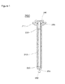
- Figure 1 is a cross sectional view illustrating a spuit controlling the quantity of its content according to an embodiment of the present invention.
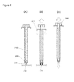
- Figure 2 is a perspective view illustrating an operation of a spuit controlling the quantity of its content according to an embodiment of the present invention.
- Figure 3 is a cross sectional view illustrating a spuit controlling the quantity of its content according to an embodiment of the present invention.
- Figure 4 is a disassembled perspective view illustrating a spuit controlling the quantity of its content according to an embodiment of the present invention.
- Figure 5 is a cross sectional view illustrating a construction of a spuit controlling the quantity of its content according to another embodiment of the present invention.
- Figure 6 is a perspective view illustrating an operation of a spuit controlling the quantity of its content according to another embodiment of the present invention.
- Figure 7 is a cross sectional view illustrating a cosmetic container with a spuit controlling the quantity of its content according to another embodiment of the present invention.
- Figure 8 is a view illustrating an engaged state of a cover and an inner cap of a cosmetic container with a spuit controlling the quantity of its content according to another embodiment of the present invention.
- Figure 9 is a perspective view illustrating a construction of a wiper of a cosmetic container with a spuit controlling the quantity of its content according to another embodiment of the present invention.
- the spuit 200 facilitating a quantitative discharge will be described.
- the spuit 200 comprises a spuit pipe 210, a cover 200, a spuit piston 230, a button 230 and a packing 250.
- the spuit pipe 210 is characterized in that a circular protrusion part 211 is formed at an upper end portion. It is preferred that the lower end of the spuit pipe 210 has a diameter decreasing toward its lower direction for the purpose of ensuring that the content is prevented from leaking when the content stored therein is transferred to a certain place.
- a cover 220 having a through hole 221 at its center is engaged at an upper end of the spuit pipe 210.
- a pressing pin 231 in the interior of the spuit pipe 210 is disposed a pressing pin 231 at its lower end.
- a spuit piston 230 is inserted into the interior of the spuit pipe 210 and passes through the through hole 221.
- a shoulder 234 to be caught by means of the lower side of the cover 220 is formed at an upper side of the spuit piston 230, so the spuit piston 230 is prevented from escaping through the upper side of the spuit pipe 210.
- a pin head 232 is further installed at a lower end of the pressing pin 231 and has a diameter corresponding to the decreased inner diameter of the lower end of the spuit pipe 210.
- it is preferred that the lower end of the spuit pipe 210 is partially blocked by the pin head 232 when content is sucked and transferred, thus preventing the leakage of content.
- a button 240 is engaged to an upper end of the spuit piston 230.
- a packing 250 having a protrusion part 251 formed along its outer surface is formed at a lower side of the circular protrusion part 21 of the spuit pipe 210.
- the cosmetic container 100 with a spuit 200 facilitating a quantitative discharge will be described.
- the cosmetic container 100 comprises a spuit 200, a container 110 and an inner cap 130.
- the container 110 serves to store content, and a concave part 111 is formed at an inner lower side, namely, at a portion where the pressing pin 231 comes into contact with, for the content to gather for a smooth suction when a little amount of content remains, and an engaging part 120 is formed at its top portion.
- an inner cap 130 having a through hole 131 formed at a central portion for the spuit 200 to sealingly insert into the through hole 131 by means of the packing 250 is detachably engaged to the engaging part 120.
- the way that the inner cap 130 is detachably engaged to the engaging part 120 can be implemented in various ways.
- threads are formed at an inner surface of the inner cap 130 and at an outer surface of the detachable engagement part 120 for screw engagements.
- an elastic wiper 150 is inserted and installed at an outer surface of the engaging part 120 with the inner diameter of the wiper being decreased toward the downward direction while corresponding to the outer diameter of the spuit pipe 210.
- an over cap 140 is further provided at an upper side of the container 100 for the purpose of detachably covering the spuit 200.
- the spuit 200 is inserted in the container 110 with content. As shown in Figure 2B , it is fully inserted by pressing the circular protrusion part 211, so the pressing pin 231 of the the lower end of the spuit piston 230 is pushed, and the spuit piston 230 rises, thus sucking a certain amount of content.
- the spuit 200 is removed and moved to a place for an actual use. A certain amount of content is discharged by pressing the button 240.
- the spuit 200' controlling its quantity comprises a spuit pipe 210', a cover 220', a spuit piston 230', and a button 240'.
- the spuit pipe 210' is formed with its upper and lower sides being open for the engagement with the spuit piston 230' and for the content to be sucked, and it is preferred that a gasket 212 with a hollow part is engaged to an open upper side.
- the inner diameter at the lower end of the spuit pipe 210' determines, and a protrusion part 213 is formed at an outer surface of the upper side for an engagement with the cover 220'.
- the cover 220' is engaged to an upper side of the spuit pipe 210, and a through hole 21 is formed at a central portion for the purpose of facilitating an engagement of the spuit piston 230'.
- An engaging protrusion 222 to be engaged to the fixing piece 132 of the inner cap 130' is formed at both sides of a lower outer surface.
- the engaging protrusion 222 is engaged to the fixing piece 132 when it rotates in one direction, thus fixing the cover 200' to the inner cap 130', and when it rotates in the other direction, the engaging protrusion 222 escapes from the fixing piece 132, thus moving the spuit 200'.
- an engaging groove 223 corresponding to the protrusion part 213 for the purpose of facilitating an engagement of the spuit pipe 210' is formed at an inner surface of the cover 220'.
- a plunger tip 235 is formed at a lower end of the spuit piston 230' which is inserted into the spuit pipe 210' and passes through the through hole 221.
- a shoulder 234' is formed at an upper side of the spuit piston 230', thus being caught by a lower end of the cover 220' for the purpose of ensuring that the spuit piston 230' is prevented from escaping trough the upper side of the spuit pipe 210'.
- the spuit piston 230' serves to such content as it moves up and down in the interior of the spuit pipe 210', so a user can use a quantitative amount of the content.
- a button 240 is engaged at an upper end of the spuit piston 230' for the purpose of facilitating an up and down movement of the spuit piston 230' as a user operates.
- the cosmetic container 100' with a spuit facilitating a quantitative discharge comprises a container 110', an inner cap 130', and a spuit 200'.
- the container 110' serves to store the content, and a concave part 111' is formed at a portion coming into contact with the plunger top 235 at an inner lower end for the purpose of ensuring that content gathers and stays for a smooth suction when content remains a little, and an engaging part 120' is formed at an upper side.
- An inner cap 130' is detachably engaged to the engaging part 120' with a through hole 131' being formed at a central portion of the inner cap 130' for the spuit 200' to detachably insert into the through hole 131'.
- the present invention is characterized in that a fixing piece 132 corresponding to the engaging protrusion 222 is formed at an inner surface of the inner cap 130' for the purpose of ensuring that the engaging protrusion 222 of the cover 220' rotates in one direction and is engaged.
- an elastic wiper 150' the inner diameter of which corresponding to the outer diameter of the spuit pipe 210' gradually decreases in its downward direction.
- a plurality of spaced-apart support protrusions 151 supporting the spuit pipe 210' are formed at an inner surface of the wiper 150', and an air hole 152 facilitating the flow of air is formed at a lower side.
- an over cap 140' is engaged at an upper side of the container 110', thus detachably covering the spuit 200'.
Landscapes
- Closures For Containers (AREA)
- Containers And Packaging Bodies Having A Special Means To Remove Contents (AREA)
Abstract
Description
- The present invention relates to a spuit controlling the quantity of its content and a cosmetic container therewith, and in particular to a spuit controlling the quantity of its content and a cosmetic container therewith which spuit comprises a
spuit pipe 210 having acircular protrusion part 211 along an upper end along an outer surface, acover 220 engaged to an upper end of thespuit pipe 210 and having a throughhole 221 at its center, aspuit piston 230 having apressing pin 231 at its lower end and being inserted in the interior of thespuit pipe 210 and passing through the throughhole 221, abutton 240 engaged at an upper end of thespuit piston 230, and apacking 250 which is installed at a lower side of thecircular protrusion part 211 of thespuit pipe 210 and having aprotrusion part 251 along a lower outer surface. - As a method for using a liquid content such as cosmetics which should be quantitatively used like an eye cream which is used by a certain amount, the content is separately packaged by a certain amount in a form of a capsule containing as much as to be used for each use. The above mentioned individual packaging method is disadvantageous in that a relatively more amount of contents might remain in the capsule after a user used it, so the individual packing method is very inefficient.
- In order to overcome the above individual packaging method, a discharge means made in a conventional spuit or syringe structure might be used after content is filled in a container or a discharge means with the construction of a push pump might be used, so the content is discharged whenever it is needed to use.
- In case of a discharge means of a conventional spuit structure, the amount of content to be sucked and discharged changes depending on the level that a user pushes, so it is almost impossible to discharge an accurate amount of the content whenever it is used.
- In addition, when a discharge means of a syringe type is used, it is generally designed for a small amount above or below 1 mℓ, so there are problems in that it is needed to make the diameter of a syringe very small or to make a stroke of a syringe piston very small. When it is needed to discharge certain content in such a way to suck content by pulling the piston of a syringe for the purpose of discharging content and then to push the piston of a syringe, the procedures of using are complicated.
- In case of the discharge means with a construction of a push pump, it is possible to discharge a certain amount of the content whenever a button is pushed; however the structure of forming the inner and outer sides of the pump is formed of a button, a suction part, a discharge part, a spring and a valve structure, so the construction is relatively complicated. Due to the natures of the push button installed at top of the container, a suction tube is generally used for the purpose of sucking content; however in this case it is impossible to discharge the content even in a state that the content remains in the container depending on the position of a suction tube.
- Accordingly, the present invention resolves the problems encountered in the conventional art. It is an object of the present invention to provide a spuit controlling the quantity of its content and a cosmetic container therewith which are characterized in that it is possible to suck an accurate amount of liquid content such as cosmetic or something and use the sucked content in a simple and inexpensive structure without handling in a complicated way.
- In addition, since the content stuck on an outer surface of the spuit pipe is collected into the container by means of a wiper during the procedure that a spuit is taken out, so the content can be used more economically, and there is not a danger of contamination which might occur due to the content stuck on an outer surface of the spuit pipe.
- To achieve the above objects, there is provided a
spuit 200 controlling the quantity of its content which comprises aspuit pipe 210 which has acircular protrusion part 211 formed at its upper end along an outer surface; acover 220 which is engaged to a upper end of thespuit pipe 210 and has a throughhole 221 at its center; aspuit piston 230 which has apressing pin 231 at a lower end and is inserted into the interior of thespuit pipe 210 and passes through a throughhole 221; abutton 240 which is engaged to an upper end of thespuit piston 230; and apacking 250 which is installed at a lower side of thecircular protrusion part 211 of thespuit pipe 210 and has aprotrusion part 251 formed along a lower outer surface. - In addition, an inner diameter of a lower end of the
spuit pipe 210 decreases, and ashoulder 234 is formed at an upper side of thespuit piston 230 and is caught by a lower end of thecover 220, and apin head 232 is installed at a lower end of thepressing pin 231 and has a diameter corresponding to a decreased inner diameter of the lower end of thepin head 232. - Meanwhile, there is provided a cosmetic container having a
spuit 200 controlling the quantity of its content which comprises acontainer 110 which includes a function storing content and has aconcave part 111 at a portion coming into contact with thepressing pin 231 at an inner lower side and has anengaging part 120 at its upper side; and an inner cap which is detachably engaged to theengaging part 120 and has a throughhole 131 formed at a center for the spuit 20 to detachably insert into thethough hole 131 in such a way to be sealed by means of apacking 250. - In addition, there are further provided a
wiper 150 which is inserted and installed at an outer surface of theengaging part 120 and is made of an elastic material in such a way that its inner diameter corresponding to an outer diameter of thespuit pipe 210 gradually decreases in its downward direction; and anover cap 140 which is installed at an upper side of thecontainer 110 in such a way to detachably cover thespuit 200. - Meanwhile, there is provided a spuit 200' controlling the quantity of its content according to another embodiment of the present invention which comprises a spuit pipe 210' an upper side and a lower side of which are open for an engagement of the
spuit piston 230' and for content to be sucked, with agasket 212 being engaged to the opened upper side; a cover 220' which is engaged to an upper side of the spuit pipe 210' and has a throughhole 221 at its center and anengaging protrusion 222 at both sides of a lower outer surface; aspuit piston 230' which has aplunger tip 235 at its lower end and is inserted into the interior of the spuit pipe 210' and passes though the throughhole 221; and a button 240' which is engaged at an upper side of thespuit piston 230'. - In addition, an inner diameter of a lower end of the spuit pipe 210' decreases, and a
protrusion part 213 engaged to the cover 220' is formed at an upper outer surface, and anengaging groove 223 corresponding to theprotrusion part 213 is formed at an inner surface of the cover 220'. - There is provided a cosmetic container having a spuit 200' controlling the quantity of its content according to another embodiment of the present invention which comprises a container 110' which has a function storing content and has a concave part 111' at a portion coming into contact with the
plunger tip 235 at an inner lower end and has an engaging part 120' at its upper side; and an inner cap 130 ' which is detachably formed at the engaging part 120' and has a through hole 131' formed at its center for the spuit 200' to detachably insert and has afixing piece 132 corresponding to theengaging protrusion 222 at an inner surface for an engagement as theengaging protrusion 222 rotates in one direction. - In addition, there are further provided a wiper 150' which is inserted into an inner surface of the engaging part 120' and is made from an elastic material in such a way that an inner diameter corresponding to an outer diameter of the spuit pipe 210' gradually decreased in its downward direction and has a plurality of spaced-
apart support protrusions 151 at its inner surface for the purpose of supporting the spuit pipe 210' and has anair hole 152 at its lower side for air to flow. - According to the present invention, the spuit controlling the quantity of its content and a cosmetic container therewith are featured in that it is possible to suck an accurate amount of liquid content such as cosmetic or something and use the sucked content in a simple and inexpensive structure without handling in a complicated way.
- In addition, since the content stuck on an outer surface of the spuit pipe is collected into the container by means of a wiper during the procedure that a spuit is taken out, so the content can be used more economically, and there is not a danger of contamination which might occur due to the content stuck on an outer surface of the spuit pipe.
-
Figure 1 is a cross sectional view illustrating a spuit controlling the quantity of its content according to an embodiment of the present invention. -
Figure 2 is a perspective view illustrating an operation of a spuit controlling the quantity of its content according to an embodiment of the present invention. -
Figure 3 is a cross sectional view illustrating a spuit controlling the quantity of its content according to an embodiment of the present invention. -
Figure 4 is a disassembled perspective view illustrating a spuit controlling the quantity of its content according to an embodiment of the present invention. -
Figure 5 is a cross sectional view illustrating a construction of a spuit controlling the quantity of its content according to another embodiment of the present invention. -
Figure 6 is a perspective view illustrating an operation of a spuit controlling the quantity of its content according to another embodiment of the present invention. -
Figure 7 is a cross sectional view illustrating a cosmetic container with a spuit controlling the quantity of its content according to another embodiment of the present invention. -
Figure 8 is a view illustrating an engaged state of a cover and an inner cap of a cosmetic container with a spuit controlling the quantity of its content according to another embodiment of the present invention. -
Figure 9 is a perspective view illustrating a construction of a wiper of a cosmetic container with a spuit controlling the quantity of its content according to another embodiment of the present invention. - The spuit controlling the quantity of its content and a cosmetic container therewith according an embodiment of the present invention will be described in details with reference to the accompanying drawings. In the drawings, the same elements or members represent the same reference numerals. The descriptions on the known art or construction will be omitted in an attempt not to make unclear the subject matters of the present invention.
- The
spuit 200 facilitating a quantitative discharge will be described. As shown inFigure 1 , thespuit 200 comprises aspuit pipe 210, acover 200, aspuit piston 230, abutton 230 and apacking 250. - As shown in
Figure 1 , thespuit pipe 210 is characterized in that acircular protrusion part 211 is formed at an upper end portion. It is preferred that the lower end of thespuit pipe 210 has a diameter decreasing toward its lower direction for the purpose of ensuring that the content is prevented from leaking when the content stored therein is transferred to a certain place. - As shown in
Figure 1 , acover 220 having a throughhole 221 at its center is engaged at an upper end of thespuit pipe 210. - As shown in
Figure 1 , in the interior of thespuit pipe 210 is disposed apressing pin 231 at its lower end. Aspuit piston 230 is inserted into the interior of thespuit pipe 210 and passes through the throughhole 221. In this case, as shown inFigure 1 , it is preferred that ashoulder 234 to be caught by means of the lower side of thecover 220 is formed at an upper side of thespuit piston 230, so thespuit piston 230 is prevented from escaping through the upper side of thespuit pipe 210. Apin head 232 is further installed at a lower end of thepressing pin 231 and has a diameter corresponding to the decreased inner diameter of the lower end of thespuit pipe 210. As shown inFigure 2 , it is preferred that the lower end of thespuit pipe 210 is partially blocked by thepin head 232 when content is sucked and transferred, thus preventing the leakage of content. - As shown in
Figure 1 , abutton 240 is engaged to an upper end of thespuit piston 230. As show inFigure 3 , it is preferred that apacking 250 having aprotrusion part 251 formed along its outer surface is formed at a lower side of the circular protrusion part 21 of thespuit pipe 210. - Next, the
cosmetic container 100 with aspuit 200 facilitating a quantitative discharge according to an embodiment of the present invention will be described. As shown inFigure 3 , thecosmetic container 100 comprises aspuit 200, acontainer 110 and aninner cap 130. - As shown in
Figure 3 , thecontainer 110 serves to store content, and aconcave part 111 is formed at an inner lower side, namely, at a portion where thepressing pin 231 comes into contact with, for the content to gather for a smooth suction when a little amount of content remains, and anengaging part 120 is formed at its top portion. - As shown in
Figure 3 , aninner cap 130 having a throughhole 131 formed at a central portion for thespuit 200 to sealingly insert into the throughhole 131 by means of thepacking 250 is detachably engaged to theengaging part 120. The way that theinner cap 130 is detachably engaged to theengaging part 120 can be implemented in various ways. As one embodiment of the above operation, as shown inFigure 3 , threads are formed at an inner surface of theinner cap 130 and at an outer surface of thedetachable engagement part 120 for screw engagements. - In order for the content stuck on the outer surface of the
spuit pipe 210 to be collected into thecontainer 110 during a procedure that thespuit 200 is taken out, as shown inFigure 3 , it is preferred that anelastic wiper 150 is inserted and installed at an outer surface of theengaging part 120 with the inner diameter of the wiper being decreased toward the downward direction while corresponding to the outer diameter of thespuit pipe 210. In addition, it is preferred that an overcap 140 is further provided at an upper side of thecontainer 100 for the purpose of detachably covering thespuit 200. - The operation of the spuit controlling the quantity of its content and a cosmetic container therewith according to an embodiment of the present invention will be described.
- As show in
Figure 2A , thespuit 200 is inserted in thecontainer 110 with content. As shown inFigure 2B , it is fully inserted by pressing thecircular protrusion part 211, so thepressing pin 231 of the the lower end of thespuit piston 230 is pushed, and thespuit piston 230 rises, thus sucking a certain amount of content. - As shown in
Figure 2C , thespuit 200 is removed and moved to a place for an actual use. A certain amount of content is discharged by pressing thebutton 240. - The spuit controlling the quantity of its content and a cosmetic container therewith according to another embodiment of the present invention will be described with reference to
Figures 5 through 9 . - First, the spuit 200' controlling its quantity according to another embodiment of the present invention comprises a spuit pipe 210', a cover 220', a
spuit piston 230', and a button 240'. - The spuit pipe 210' is formed with its upper and lower sides being open for the engagement with the
spuit piston 230' and for the content to be sucked, and it is preferred that agasket 212 with a hollow part is engaged to an open upper side. - The inner diameter at the lower end of the spuit pipe 210' determines, and a
protrusion part 213 is formed at an outer surface of the upper side for an engagement with the cover 220'. - The cover 220' is engaged to an upper side of the
spuit pipe 210, and a through hole 21 is formed at a central portion for the purpose of facilitating an engagement of thespuit piston 230'. An engagingprotrusion 222 to be engaged to the fixingpiece 132 of the inner cap 130' is formed at both sides of a lower outer surface. - The engaging
protrusion 222 is engaged to the fixingpiece 132 when it rotates in one direction, thus fixing the cover 200' to the inner cap 130', and when it rotates in the other direction, the engagingprotrusion 222 escapes from the fixingpiece 132, thus moving the spuit 200'. - It is preferred that an engaging
groove 223 corresponding to theprotrusion part 213 for the purpose of facilitating an engagement of the spuit pipe 210' is formed at an inner surface of the cover 220'. - A
plunger tip 235 is formed at a lower end of thespuit piston 230' which is inserted into the spuit pipe 210' and passes through the throughhole 221. In this case, a shoulder 234' is formed at an upper side of thespuit piston 230', thus being caught by a lower end of the cover 220' for the purpose of ensuring that thespuit piston 230' is prevented from escaping trough the upper side of the spuit pipe 210'. - The
spuit piston 230' serves to such content as it moves up and down in the interior of the spuit pipe 210', so a user can use a quantitative amount of the content. - As shown in
Figure 5 , it is preferred that abutton 240 is engaged at an upper end of thespuit piston 230' for the purpose of facilitating an up and down movement of thespuit piston 230' as a user operates. - Next, the spuit controlling the quantity of its content and a cosmetic container therewith according to another embodiment of the present invention will be described.
- The cosmetic container 100' with a spuit facilitating a quantitative discharge according to another embodiment of the present invention comprises a container 110', an inner cap 130', and a spuit 200'.
- The container 110' serves to store the content, and a concave part 111' is formed at a portion coming into contact with the
plunger top 235 at an inner lower end for the purpose of ensuring that content gathers and stays for a smooth suction when content remains a little, and an engaging part 120' is formed at an upper side. - An inner cap 130' is detachably engaged to the engaging part 120' with a through hole 131' being formed at a central portion of the inner cap 130' for the spuit 200' to detachably insert into the through hole 131'. The present invention is characterized in that a fixing
piece 132 corresponding to the engagingprotrusion 222 is formed at an inner surface of the inner cap 130' for the purpose of ensuring that the engagingprotrusion 222 of the cover 220' rotates in one direction and is engaged. When the cover 220' rotates in one direction, the spuit 200' is fixed at the inner cap 130', and when the cover 220' rotates in the other direction, the spuit 200' disengages from the inner cap 130'. - In order for the content stuck on the outer surface of the spuit pipe 210' to gather into the container 110' during a procedure that the
spuit 200's is taken out, it is preferred that at an inner surface of the engaging part 120' is provided an elastic wiper 150' the inner diameter of which corresponding to the outer diameter of the spuit pipe 210' gradually decreases in its downward direction. - A plurality of spaced-apart
support protrusions 151 supporting the spuit pipe 210' are formed at an inner surface of the wiper 150', and anair hole 152 facilitating the flow of air is formed at a lower side. - In addition, it is preferred that an over cap 140' is engaged at an upper side of the container 110', thus detachably covering the spuit 200'.
- As the present invention may be embodied in several forms without departing from the spirit or essential characteristics thereof, it should also be understood that the above-described examples are not limited by any of the details of the foregoing description, unless otherwise specified, but rather should be construed broadly within its spirit and scope as defined in the appended claims, and therefore all changes and modifications that fall within the meets and bounds of the claims, or equivalences of such meets and bounds are therefore intended to be embraced by the appended claims.
Claims (8)
- A spuit controlling the quantity of its content, comprising:a spuit pipe 210 which has a circular protrusion part 211 formed at its upper end along an outer surface;a cover 220 which is engaged to a upper end of the spuit pipe 210 and has a through hole 221 at its center;a spuit piston 230 which has a pressing pin 231 at a lower end and is inserted into the interior of the spuit pipe 210 and passes through a through hole 221;a button 240 which is engaged to an upper end of the spuit piston 230; anda packing 250 which is installed at a lower side of the circular protrusion part 211 of the spuit pipe 210 and has a protrusion part 251 formed along a lower outer surface.
- The spuit of claim 1, wherein an inner diameter of a lower end of the spuit pipe 210 decreases, and a shoulder 234 is formed at an upper side of the spuit piston 230 and is caught by a lower end of the cover 220, and a pin head 232 is installed at a lower end of the pressing pin 231 and has a diameter corresponding to a decreased inner diameter of the lower end of the pin head 232.
- A cosmetic container having a spuit controlling the quantity of its content of either claim 1 or claim 2, comprising:a container 110 which includes a function storing content and has a concave part 111 at a portion coming into contact with the pressing pin 231 at an inner lower side and has an engaging part 120 at its upper side; andan inner cap which is detachably engaged to the engaging part 120 and has a through hole 131 formed at a center for the spuit 20 to detachably insert into the though hole 131 in such a way to be sealed by means of a packing 250.
- The container of claim 3, further comprising:a wiper 150 which is inserted and installed at an outer surface of the engaging part 120 and is made of an elastic material in such a way that its inner diameter corresponding to an outer diameter of the spuit pipe 210 gradually decreases in its downward direction; andan over cap 140 which is installed at an upper side of the container 110 in such a way to detachably cover the spuit 200.
- A spuit controlling the quantity of its content, comprising:a spuit pipe 210' an upper side and a lower side of which are open for an engagement of the spuit piston 230' and for content to be sucked, with a gasket 212 being engaged to the opened upper side;a cover 220' which is engaged to an upper side of the spuit pipe 210' and has a through hole 221 at its center and an engaging protrusion 222 at both sides of a lower outer surface;a spuit piston 230' which has a plunger tip 235 at its lower end and is inserted into the interior of the spuit pipe 210' and passes though the through hole 221; anda button 240' which is engaged at an upper side of the spuit piston 230'.
- The spuit of claim 5, wherein an inner diameter of a lower end of the spuit pipe 210' decreases, and a protrusion part 213 engaged to the cover 220' is formed at an upper outer surface, and an engaging groove 223 corresponding to the protrusion part 213 is formed at an inner surface of the cover 220'.
- A cosmetic container having a spuit controlling the quantity of its content of either claim 5 or claim 6, comprising:a container 110' which has a function storing content and has a concave part 111' at a portion coming into contact with the plunger tip 235 at an inner lower end and has an engaging part 120' at its upper side; andan inner cap 130' which is detachably formed at the engaging part 120' and has a through hole 131' formed at its center for the spuit 200' to detachably insert and has a fixing piece 132 corresponding to the engaging protrusion 222 at an inner surface for an engagement as the engaging protrusion 222 rotates in one direction.
- The container of claim 7, further comprising:a wiper 150' which is inserted into an inner surface of the engaging part 120' and is made from an elastic material in such a way that an inner diameter corresponding to an outer diameter of the spuit pipe 210' gradually decreased in its downward direction and has a plurality of spaced-apart support protrusions 151 at its inner surface for the purpose of supporting the spuit pipe 210' and has an air hole 152 at its lower side for air to flow.
Applications Claiming Priority (3)
| Application Number | Priority Date | Filing Date | Title |
|---|---|---|---|
| KR20090099388 | 2009-10-19 | ||
| PCT/KR2009/007576 WO2011049267A1 (en) | 2009-10-19 | 2009-12-17 | Liquid dropper allowing quantitative withdrawal, and a cosmetic container equipped with the same |
| KR1020090125933A KR101083262B1 (en) | 2009-10-19 | 2009-12-17 | Eye dropper capable of quantitative withdrawal and cosmetic container having same |
Publications (2)
| Publication Number | Publication Date |
|---|---|
| EP2491814A1 true EP2491814A1 (en) | 2012-08-29 |
| EP2491814A4 EP2491814A4 (en) | 2015-01-21 |
Family
ID=44048670
Family Applications (1)
| Application Number | Title | Priority Date | Filing Date |
|---|---|---|---|
| EP09850626.4A Withdrawn EP2491814A4 (en) | 2009-10-19 | 2009-12-17 | Liquid dropper allowing quantitative withdrawal, and a cosmetic container equipped with the same |
Country Status (5)
| Country | Link |
|---|---|
| US (2) | US9427064B2 (en) |
| EP (1) | EP2491814A4 (en) |
| KR (1) | KR101083262B1 (en) |
| CN (1) | CN102595963B (en) |
| WO (1) | WO2011049267A1 (en) |
Cited By (2)
| Publication number | Priority date | Publication date | Assignee | Title |
|---|---|---|---|---|
| WO2016171442A1 (en) * | 2015-04-24 | 2016-10-27 | Daewoong Pharmaceutical Co., Ltd. | Automatic spuit type cap and automatic spuit type vessel including the same |
| CN106268996A (en) * | 2016-09-29 | 2017-01-04 | 黎柏麟 | One brood lac dropper |
Families Citing this family (48)
| Publication number | Priority date | Publication date | Assignee | Title |
|---|---|---|---|---|
| USD717664S1 (en) * | 2012-03-13 | 2014-11-18 | S.C. Johnson & Son, Inc. | Pump dispenser |
| JP5938828B2 (en) * | 2012-05-16 | 2016-06-22 | ヨンウー カンパニー,リミテッド | Cosmetic container with dropper capable of quantitative withdrawal and discharge |
| FR2991307B1 (en) * | 2012-06-01 | 2015-05-15 | Chanel Parfums Beaute | VISCOUS PRODUCT DISPENSER |
| KR101328457B1 (en) * | 2012-09-03 | 2013-11-13 | (주)연우 | A spuit type cosmetic vessel for residual quantity consumption |
| KR101432190B1 (en) * | 2012-10-04 | 2014-08-20 | (주)연우 | A spuit type cosmetic vessel |
| FR2997935B1 (en) * | 2012-11-13 | 2015-05-29 | Aptar France Sas | FLUID PRODUCT DISPENSER. |
| TWM455413U (en) * | 2013-01-28 | 2013-06-21 | Well Max Beauty Lab Co Ltd | Pipette container |
| KR101442500B1 (en) * | 2013-04-16 | 2014-09-26 | (주)연우 | Dispenser for liquid container |
| WO2015023061A1 (en) | 2013-08-14 | 2015-02-19 | 주식회사 에프에스코리아 | Apparatus for automatically filling pipette |
| KR101500601B1 (en) * | 2013-08-14 | 2015-03-10 | 이영주 | Pipette apparatus for automatic filling up |
| KR101491383B1 (en) * | 2013-12-06 | 2015-02-23 | 최종서 | Structure of cap for vessel |
| KR101491385B1 (en) * | 2013-12-06 | 2015-02-10 | 최종서 | Structure of cap for vessel |
| KR101491384B1 (en) * | 2013-12-06 | 2015-02-10 | 최종서 | Structure of cap for vessel |
| KR101587785B1 (en) * | 2014-05-20 | 2016-01-22 | (주)연우 | Dispenser for liquid container |
| USD759501S1 (en) * | 2014-10-20 | 2016-06-21 | F.S. Korea Industries Inc | Cosmetics container |
| USD758204S1 (en) * | 2014-10-20 | 2016-06-07 | F.S. Korea Industries Inc | Cosmetics container |
| US9686976B2 (en) | 2015-03-02 | 2017-06-27 | Bayer Cropscience Lp | Variable metered airless applicator with cartridge |
| MA41906A (en) | 2015-04-10 | 2018-02-13 | Dompe Farm Spa | EYE DROP DISTRIBUTION DEVICE |
| KR101768889B1 (en) * | 2015-05-08 | 2017-08-17 | (주)연우 | The container controlling the quantity of its content |
| WO2016182219A1 (en) * | 2015-05-08 | 2016-11-17 | (주)연우 | Container capable of dispensing fixed quantity of liquid content |
| KR101713048B1 (en) * | 2015-05-11 | 2017-03-07 | (주)연우 | The container controlling the quantity of its content |
| KR101714348B1 (en) * | 2015-06-22 | 2017-03-09 | (주)연우 | Vessel with a sponge wiper |
| ITUA20162072A1 (en) | 2016-06-30 | 2017-12-30 | Platinum Corp Srl | Volume controlled dropper |
| US10098437B2 (en) * | 2016-08-09 | 2018-10-16 | Amorepacific Corporation | Spuit-type container including flocking tip having temporary storage |
| CN106442684B (en) * | 2016-08-15 | 2018-10-19 | 大连医科大学 | Quantitative oil dropper for two-dimensional electrophoresis rubber strip hydration sealing layer |
| KR101760627B1 (en) * | 2016-12-06 | 2017-07-24 | 주식회사 삼화플라스틱 | Lip gross vessel |
| CN108820582A (en) * | 2018-08-01 | 2018-11-16 | 赵华勇 | A kind of oral medicament taking bottle lid of quantitative medical treatment |
| CN112789115A (en) * | 2018-08-02 | 2021-05-11 | 斯勒冈分配系统公司 | Dropper dispenser and method of use |
| CA3114373A1 (en) * | 2018-09-29 | 2020-04-02 | Robert J. Petcavich | Natural product composition for stimulating hair growth |
| KR102141303B1 (en) * | 2019-03-13 | 2020-08-04 | 신은주 | Syringe type ampoule whith easy discharge of contents |
| KR102106731B1 (en) * | 2019-05-10 | 2020-05-04 | 김용기 | Cosmetic vessel |
| US11957230B2 (en) | 2019-06-23 | 2024-04-16 | Toly Management Ltd. | Cosmetic applicator with heat transfer component |
| US11219292B2 (en) * | 2019-06-23 | 2022-01-11 | Toly Managment Ltd. | Cosmetic applicator with heat transfer component |
| WO2021056966A1 (en) * | 2019-09-29 | 2021-04-01 | 广州蓝月亮实业有限公司 | Liquid quantifying method and quantifying bottle |
| USD1088888S1 (en) | 2019-10-07 | 2025-08-19 | Berlin Packaging, Llc | Dosing container |
| US10875688B1 (en) | 2019-11-25 | 2020-12-29 | Berlin Packaging, Llc | Child resistant senior friendly bottle packaging for liquids |
| US11161657B2 (en) | 2019-11-25 | 2021-11-02 | Berlin Packaging, Llc | Child resistant senior friendly bottle packaging for liquids |
| KR200494062Y1 (en) * | 2020-05-26 | 2021-07-23 | 주식회사 에프에스코리아 | Cosmetic dropper |
| FR3111339B1 (en) * | 2020-06-11 | 2023-02-10 | Oreal | Assembly for packaging and dispensing a fluid product, in particular a cosmetic product |
| USD1012725S1 (en) | 2020-10-07 | 2024-01-30 | Berlin Packaging, Llc | Dosing container |
| US20220331791A1 (en) * | 2021-04-16 | 2022-10-20 | APC Packaging, LLC. | Dropper |
| KR102525045B1 (en) * | 2021-06-04 | 2023-04-24 | 주식회사 팬그램 | Perfume refill device and adapter for refilling perfume used therein |
| US12390804B2 (en) * | 2021-06-12 | 2025-08-19 | Control Ltd. | Modified dropper device and method for accurate dosing |
| CN218578496U (en) * | 2022-05-18 | 2023-03-07 | 洽兴包装工业(中国)有限公司 | Drip tube cover |
| KR102603768B1 (en) * | 2023-07-03 | 2023-11-17 | 빅벨 주식회사 | A syringe-type cosmetic container |
| CN121487878A (en) * | 2023-07-31 | 2026-02-06 | 莱雅公司 | Container for automatically removing contents |
| CN116851052B (en) * | 2023-08-31 | 2025-07-22 | 江苏科华医疗器械科技有限公司 | Closed type dropper device for detection and application method thereof |
| CN117328239B (en) * | 2023-10-11 | 2025-10-28 | 广州科联精密机器股份有限公司 | A syringe-type liquid dispensing device |
Family Cites Families (40)
| Publication number | Priority date | Publication date | Assignee | Title |
|---|---|---|---|---|
| US14524A (en) * | 1856-03-25 | Syringe-bottle for medicinal agents | ||
| GB191207068A (en) * | 1912-03-22 | 1913-05-22 | Ignatius Knaster | Improvements in and relating to the Application or Administration of Liquids, Semi-Liquids, and the like to the Human Body or other Objects. |
| US1178512A (en) * | 1914-05-15 | 1916-04-11 | Thomas V Garlock | Liquid-extractor. |
| US1340078A (en) * | 1918-12-24 | 1920-05-11 | John S Peoples | Container |
| US1453445A (en) * | 1922-02-01 | 1923-05-01 | William J Covell | Dispensing container |
| US1453444A (en) * | 1922-02-01 | 1923-05-01 | William J Covell | Dosage bottle |
| US2129144A (en) * | 1937-09-17 | 1938-09-06 | Lancaster Inc | Liquid meter |
| US2173662A (en) * | 1938-06-08 | 1939-09-19 | Adolph M Plattring | Dropper |
| US2845963A (en) * | 1956-04-16 | 1958-08-05 | Johnson & Johnson | Dispensing bottles |
| US3059342A (en) * | 1959-12-18 | 1962-10-23 | Albert H Beal | Well survey instruments |
| US3094245A (en) * | 1960-05-02 | 1963-06-18 | Economics Lab | Liquid dispenser |
| CH410282A (en) * | 1963-02-20 | 1966-03-31 | Wartmann Emilio | Device for withdrawing certain amounts of liquid from a bottle |
| DE2711124C2 (en) * | 1977-03-15 | 1979-05-10 | Labora Mannheim Gmbh Fuer Labortechnik, 6800 Mannheim | Hand pipette |
| DE7824115U1 (en) * | 1978-08-12 | 1978-11-16 | Arzneimittel Gmbh | Liquid container especially for medicines |
| US4376591A (en) * | 1980-02-04 | 1983-03-15 | Proffer Charles L | Container cap with neck abutting retractable liquid pickup structure |
| US4759755A (en) * | 1985-03-05 | 1988-07-26 | Lincoln Diagnostics, Inc. | Device for transferring liquid from a vial to a multi-pointed applicator |
| US4941519A (en) * | 1988-08-19 | 1990-07-17 | American Sterilizer Company | Liquid feed system using a non-reusable container |
| CA1327715C (en) * | 1989-04-04 | 1994-03-15 | Ramana Davloor | Liquid sampling device |
| WO1995001924A1 (en) * | 1993-07-08 | 1995-01-19 | Janssen Pharmaceutica N.V. | Childproof dosing device |
| US5445038A (en) * | 1993-12-06 | 1995-08-29 | Safety-Kleen Corp. | Apparatus for sampling fluids in containers |
| JPH08256830A (en) * | 1995-03-27 | 1996-10-08 | Kao Corp | Container with applicator |
| US5836359A (en) * | 1995-06-30 | 1998-11-17 | Concept Workshop Worldwide, Llc | Liquid dosage dispensers |
| US6045003A (en) * | 1995-06-30 | 2000-04-04 | Concept Workshop Worldwide, Llc | Liquid dosage dispensers |
| CA2185292A1 (en) * | 1995-09-15 | 1997-03-16 | James C. Smith | Positive displacement liquid drawing and dispensing apparatus and method |
| IT1291850B1 (en) * | 1997-05-02 | 1999-01-21 | Project S A S Di Menichelli Ma | DOSING PLUG FOR SCREW CLOSING OF LIQUID BOTTLES, WITH SYRINGE DEVICE FOR WITHDRAWING DOSED QUANTITIES |
| IT1291848B1 (en) * | 1997-05-02 | 1999-01-21 | Project S A S Di Menichelli Ma | STOPPER FOR BOTTLES WITH DEVICE FOR WITHDRAWING DOSED QUANTITIES OF THE LIQUID CONTAINED IN THESE BOTTLES |
| AU762343B2 (en) * | 1998-09-30 | 2003-06-26 | Comar, Inc. | Exact dose dispenser device assembly |
| IT1305060B1 (en) * | 1998-12-18 | 2001-04-10 | Project S A S Di Menichelli Ma | BOTTLE AND LIQUID DISPENSING DEVICE WITH A CYLINDER-PISTON COMPLEX ASSOCIATED WITH THE BOTTLE SHUTTER |
| US6520384B2 (en) * | 2001-04-30 | 2003-02-18 | Ketan C. Mehta | Apparatus and method for nasal rinse |
| JP2004065467A (en) * | 2002-08-05 | 2004-03-04 | Bb Laboratories Inc | Cosmetic tools for applying high viscosity fluid cosmetics |
| KR200338723Y1 (en) * | 2003-08-06 | 2004-01-24 | (주)코레드 | Injector style case |
| US20050070853A1 (en) * | 2003-08-25 | 2005-03-31 | Brian Gatton | Medicament dispensing assembly |
| US7429141B2 (en) * | 2004-03-02 | 2008-09-30 | L'oreal | Applicator for makeup or beauty care products |
| GB2419821B (en) * | 2004-09-30 | 2008-08-06 | Peter Bartingale | Improvements to fragrance inhalers and applicators |
| CH695412A5 (en) * | 2004-10-19 | 2006-05-15 | Labo Cosprophar Ag | Method and kit particularly for applying a cosmetic product. |
| US20070221686A1 (en) * | 2006-03-27 | 2007-09-27 | Taesung Industrial Co., Ltd. | Liquid pump dispenser |
| US7434602B2 (en) * | 2006-08-03 | 2008-10-14 | University Of Medicine & Dentistry Of New Jersey | Drip chamber dropper bottle |
| KR200438535Y1 (en) | 2007-05-15 | 2008-02-26 | (주)아모레퍼시픽 | Dropper type cosmetic container with fixed-dose discharge |
| KR200440620Y1 (en) * | 2007-05-15 | 2008-06-20 | (주)아모레퍼시픽 | Eye dropper type cosmetic container |
| US8403008B2 (en) * | 2010-05-24 | 2013-03-26 | Elc Management, Llc | Metered dose applicator with light for activating product |
-
2009
- 2009-12-17 KR KR1020090125933A patent/KR101083262B1/en not_active Expired - Fee Related
- 2009-12-17 EP EP09850626.4A patent/EP2491814A4/en not_active Withdrawn
- 2009-12-17 CN CN200980162450.8A patent/CN102595963B/en not_active Expired - Fee Related
- 2009-12-17 WO PCT/KR2009/007576 patent/WO2011049267A1/en not_active Ceased
- 2009-12-17 US US13/503,029 patent/US9427064B2/en not_active Expired - Fee Related
-
2014
- 2014-12-17 US US14/574,338 patent/US20150101705A1/en not_active Abandoned
Cited By (3)
| Publication number | Priority date | Publication date | Assignee | Title |
|---|---|---|---|---|
| WO2016171442A1 (en) * | 2015-04-24 | 2016-10-27 | Daewoong Pharmaceutical Co., Ltd. | Automatic spuit type cap and automatic spuit type vessel including the same |
| CN106268996A (en) * | 2016-09-29 | 2017-01-04 | 黎柏麟 | One brood lac dropper |
| CN106268996B (en) * | 2016-09-29 | 2019-01-08 | 广西南岜仔科技有限公司 | A kind of rubber head dropper |
Also Published As
| Publication number | Publication date |
|---|---|
| EP2491814A4 (en) | 2015-01-21 |
| CN102595963B (en) | 2015-06-17 |
| US20150101705A1 (en) | 2015-04-16 |
| KR101083262B1 (en) | 2011-11-17 |
| WO2011049267A1 (en) | 2011-04-28 |
| CN102595963A (en) | 2012-07-18 |
| US9427064B2 (en) | 2016-08-30 |
| US20120261029A1 (en) | 2012-10-18 |
| KR20110043388A (en) | 2011-04-27 |
Similar Documents
| Publication | Publication Date | Title |
|---|---|---|
| US9427064B2 (en) | Liquid dropper allowing quantitative withdrawal, and a cosmetic container equipped with the same | |
| KR101406893B1 (en) | Dispenser for liquid container | |
| KR101587785B1 (en) | Dispenser for liquid container | |
| US5967377A (en) | Metered liquid dispenser with lift fill mechanism | |
| KR101442500B1 (en) | Dispenser for liquid container | |
| KR101789573B1 (en) | Spuit type cosmetics container | |
| KR101152159B1 (en) | Dispenser for liquid container | |
| EP1982929A2 (en) | Airless dispensing pump container with an airtight push down type nozzle head | |
| KR101785716B1 (en) | Spuit type cosmetic vessel | |
| US5967379A (en) | Liquid dispenser having a container with a dispensing device | |
| US20020088827A1 (en) | Variable volume wine bottle | |
| KR102750233B1 (en) | Assembly and method for providing micro-volume droplets from a squeeze bottle | |
| JP3905934B2 (en) | Liquid quantity device that can be attached to a container | |
| KR101202092B1 (en) | The cosmetic container having spuit controlling the quantity of its content | |
| KR20130060742A (en) | Dispenser for liquid container | |
| KR200452316Y1 (en) | Metering dispenser for liquid containers | |
| KR20190000556A (en) | cosmetic tool and cosmetic vessel | |
| KR101780903B1 (en) | Cosmetic vessel of automatic filling up spuit type | |
| ES2348798T3 (en) | FLUID PRODUCT DISTRIBUTION DEVICE. | |
| JP5242494B2 (en) | Container with inner stopper | |
| KR20220101840A (en) | Cosmetic container | |
| KR101454748B1 (en) | The container controlling the quantity of its content | |
| KR101239027B1 (en) | Automatic filling up spuit | |
| KR102404972B1 (en) | Cosmetic dropper | |
| KR101464447B1 (en) | The cosmetic container having spuit controlling the quantity of its content |
Legal Events
| Date | Code | Title | Description |
|---|---|---|---|
| PUAI | Public reference made under article 153(3) epc to a published international application that has entered the european phase |
Free format text: ORIGINAL CODE: 0009012 |
|
| 17P | Request for examination filed |
Effective date: 20120514 |
|
| AK | Designated contracting states |
Kind code of ref document: A1 Designated state(s): AT BE BG CH CY CZ DE DK EE ES FI FR GB GR HR HU IE IS IT LI LT LU LV MC MK MT NL NO PL PT RO SE SI SK SM TR |
|
| DAX | Request for extension of the european patent (deleted) | ||
| A4 | Supplementary search report drawn up and despatched |
Effective date: 20141222 |
|
| RIC1 | Information provided on ipc code assigned before grant |
Ipc: A45D 40/00 20060101AFI20141215BHEP Ipc: A45D 34/04 20060101ALI20141215BHEP Ipc: A45D 34/00 20060101ALI20141215BHEP |
|
| 17Q | First examination report despatched |
Effective date: 20180327 |
|
| STAA | Information on the status of an ep patent application or granted ep patent |
Free format text: STATUS: THE APPLICATION IS DEEMED TO BE WITHDRAWN |
|
| 18D | Application deemed to be withdrawn |
Effective date: 20181009 |