EP2490785B1 - Geprägtes flüssigkeitsfilterelement - Google Patents
Geprägtes flüssigkeitsfilterelement Download PDFInfo
- Publication number
- EP2490785B1 EP2490785B1 EP10825507.6A EP10825507A EP2490785B1 EP 2490785 B1 EP2490785 B1 EP 2490785B1 EP 10825507 A EP10825507 A EP 10825507A EP 2490785 B1 EP2490785 B1 EP 2490785B1
- Authority
- EP
- European Patent Office
- Prior art keywords
- embossing
- embossment
- elongated
- row
- embossing row
- Prior art date
- Legal status (The legal status is an assumption and is not a legal conclusion. Google has not performed a legal analysis and makes no representation as to the accuracy of the status listed.)
- Active
Links
Images


Classifications
-
- B—PERFORMING OPERATIONS; TRANSPORTING
- B01—PHYSICAL OR CHEMICAL PROCESSES OR APPARATUS IN GENERAL
- B01D—SEPARATION
- B01D29/00—Filters with filtering elements stationary during filtration, e.g. pressure or suction filters, not covered by groups B01D24/00 - B01D27/00; Filtering elements therefor
- B01D29/01—Filters with filtering elements stationary during filtration, e.g. pressure or suction filters, not covered by groups B01D24/00 - B01D27/00; Filtering elements therefor with flat filtering elements
- B01D29/012—Making filtering elements
-
- B—PERFORMING OPERATIONS; TRANSPORTING
- B01—PHYSICAL OR CHEMICAL PROCESSES OR APPARATUS IN GENERAL
- B01D—SEPARATION
- B01D46/00—Filters or filtering processes specially modified for separating dispersed particles from gases or vapours
- B01D46/0001—Making filtering elements
-
- B—PERFORMING OPERATIONS; TRANSPORTING
- B01—PHYSICAL OR CHEMICAL PROCESSES OR APPARATUS IN GENERAL
- B01D—SEPARATION
- B01D29/00—Filters with filtering elements stationary during filtration, e.g. pressure or suction filters, not covered by groups B01D24/00 - B01D27/00; Filtering elements therefor
- B01D29/01—Filters with filtering elements stationary during filtration, e.g. pressure or suction filters, not covered by groups B01D24/00 - B01D27/00; Filtering elements therefor with flat filtering elements
- B01D29/016—Filters with filtering elements stationary during filtration, e.g. pressure or suction filters, not covered by groups B01D24/00 - B01D27/00; Filtering elements therefor with flat filtering elements with corrugated, folded or wound filtering elements
-
- B—PERFORMING OPERATIONS; TRANSPORTING
- B01—PHYSICAL OR CHEMICAL PROCESSES OR APPARATUS IN GENERAL
- B01D—SEPARATION
- B01D29/00—Filters with filtering elements stationary during filtration, e.g. pressure or suction filters, not covered by groups B01D24/00 - B01D27/00; Filtering elements therefor
- B01D29/01—Filters with filtering elements stationary during filtration, e.g. pressure or suction filters, not covered by groups B01D24/00 - B01D27/00; Filtering elements therefor with flat filtering elements
- B01D29/05—Filters with filtering elements stationary during filtration, e.g. pressure or suction filters, not covered by groups B01D24/00 - B01D27/00; Filtering elements therefor with flat filtering elements supported
- B01D29/07—Filters with filtering elements stationary during filtration, e.g. pressure or suction filters, not covered by groups B01D24/00 - B01D27/00; Filtering elements therefor with flat filtering elements supported with corrugated, folded or wound filtering sheets
-
- B—PERFORMING OPERATIONS; TRANSPORTING
- B01—PHYSICAL OR CHEMICAL PROCESSES OR APPARATUS IN GENERAL
- B01D—SEPARATION
- B01D29/00—Filters with filtering elements stationary during filtration, e.g. pressure or suction filters, not covered by groups B01D24/00 - B01D27/00; Filtering elements therefor
- B01D29/11—Filters with filtering elements stationary during filtration, e.g. pressure or suction filters, not covered by groups B01D24/00 - B01D27/00; Filtering elements therefor with bag, cage, hose, tube, sleeve or like filtering elements
- B01D29/111—Making filtering elements
-
- B—PERFORMING OPERATIONS; TRANSPORTING
- B01—PHYSICAL OR CHEMICAL PROCESSES OR APPARATUS IN GENERAL
- B01D—SEPARATION
- B01D29/00—Filters with filtering elements stationary during filtration, e.g. pressure or suction filters, not covered by groups B01D24/00 - B01D27/00; Filtering elements therefor
- B01D29/11—Filters with filtering elements stationary during filtration, e.g. pressure or suction filters, not covered by groups B01D24/00 - B01D27/00; Filtering elements therefor with bag, cage, hose, tube, sleeve or like filtering elements
- B01D29/13—Supported filter elements
- B01D29/15—Supported filter elements arranged for inward flow filtration
- B01D29/21—Supported filter elements arranged for inward flow filtration with corrugated, folded or wound sheets
-
- B—PERFORMING OPERATIONS; TRANSPORTING
- B01—PHYSICAL OR CHEMICAL PROCESSES OR APPARATUS IN GENERAL
- B01D—SEPARATION
- B01D29/00—Filters with filtering elements stationary during filtration, e.g. pressure or suction filters, not covered by groups B01D24/00 - B01D27/00; Filtering elements therefor
- B01D29/44—Edge filtering elements, i.e. using contiguous impervious surfaces
-
- B—PERFORMING OPERATIONS; TRANSPORTING
- B01—PHYSICAL OR CHEMICAL PROCESSES OR APPARATUS IN GENERAL
- B01D—SEPARATION
- B01D39/00—Filtering material for liquid or gaseous fluids
-
- B—PERFORMING OPERATIONS; TRANSPORTING
- B01—PHYSICAL OR CHEMICAL PROCESSES OR APPARATUS IN GENERAL
- B01D—SEPARATION
- B01D46/00—Filters or filtering processes specially modified for separating dispersed particles from gases or vapours
- B01D46/10—Particle separators, e.g. dust precipitators, using filter plates, sheets or pads having plane surfaces
-
- B—PERFORMING OPERATIONS; TRANSPORTING
- B01—PHYSICAL OR CHEMICAL PROCESSES OR APPARATUS IN GENERAL
- B01D—SEPARATION
- B01D46/00—Filters or filtering processes specially modified for separating dispersed particles from gases or vapours
- B01D46/52—Particle separators, e.g. dust precipitators, using filters embodying folded corrugated or wound sheet material
- B01D46/521—Particle separators, e.g. dust precipitators, using filters embodying folded corrugated or wound sheet material using folded, pleated material
- B01D46/522—Particle separators, e.g. dust precipitators, using filters embodying folded corrugated or wound sheet material using folded, pleated material with specific folds, e.g. having different lengths
-
- B—PERFORMING OPERATIONS; TRANSPORTING
- B01—PHYSICAL OR CHEMICAL PROCESSES OR APPARATUS IN GENERAL
- B01D—SEPARATION
- B01D46/00—Filters or filtering processes specially modified for separating dispersed particles from gases or vapours
- B01D46/52—Particle separators, e.g. dust precipitators, using filters embodying folded corrugated or wound sheet material
- B01D46/521—Particle separators, e.g. dust precipitators, using filters embodying folded corrugated or wound sheet material using folded, pleated material
- B01D46/523—Particle separators, e.g. dust precipitators, using filters embodying folded corrugated or wound sheet material using folded, pleated material with means for maintaining spacing between the pleats or folds
-
- C—CHEMISTRY; METALLURGY
- C09—DYES; PAINTS; POLISHES; NATURAL RESINS; ADHESIVES; COMPOSITIONS NOT OTHERWISE PROVIDED FOR; APPLICATIONS OF MATERIALS NOT OTHERWISE PROVIDED FOR
- C09J—ADHESIVES; NON-MECHANICAL ASPECTS OF ADHESIVE PROCESSES IN GENERAL; ADHESIVE PROCESSES NOT PROVIDED FOR ELSEWHERE; USE OF MATERIALS AS ADHESIVES
- C09J5/00—Adhesive processes in general; Adhesive processes not provided for elsewhere, e.g. relating to primers
- C09J5/02—Adhesive processes in general; Adhesive processes not provided for elsewhere, e.g. relating to primers involving pretreatment of the surfaces to be joined
-
- B—PERFORMING OPERATIONS; TRANSPORTING
- B01—PHYSICAL OR CHEMICAL PROCESSES OR APPARATUS IN GENERAL
- B01D—SEPARATION
- B01D2201/00—Details relating to filtering apparatus
- B01D2201/12—Pleated filters
-
- Y—GENERAL TAGGING OF NEW TECHNOLOGICAL DEVELOPMENTS; GENERAL TAGGING OF CROSS-SECTIONAL TECHNOLOGIES SPANNING OVER SEVERAL SECTIONS OF THE IPC; TECHNICAL SUBJECTS COVERED BY FORMER USPC CROSS-REFERENCE ART COLLECTIONS [XRACs] AND DIGESTS
- Y10—TECHNICAL SUBJECTS COVERED BY FORMER USPC
- Y10T—TECHNICAL SUBJECTS COVERED BY FORMER US CLASSIFICATION
- Y10T156/00—Adhesive bonding and miscellaneous chemical manufacture
- Y10T156/10—Methods of surface bonding and/or assembly therefor
- Y10T156/1002—Methods of surface bonding and/or assembly therefor with permanent bending or reshaping or surface deformation of self sustaining lamina
- Y10T156/1039—Surface deformation only of sandwich or lamina [e.g., embossed panels]
Definitions
- This invention relates to a fluid filter element and method of forming the same.
- Fluid filter elements are well known and are widely used in fluid filters for varying areas of use, including hydrodynamic machines and air-conditioning engineering. Their meander-shaped or zig-zag structure provides a substantially increased filter area, in relation to a fixed afflux flow cross-section. In order to fix the fold walls of such a structure relative to each and to support them with respect to each other, various different kinds of design configurations have been developed. Filters with depressions which are embossed into the flat filter material and which, when the material is folded, bear against each other and support each other are known.
- US Patent Number 6,685,833 assigned to LPD technologies discloses a filter element comprising an embossed flat filter material which is folded so as to define a plurality of substantially adjacent walls, each wall having an embossing comprising a first embossing portion which extends from one side of said wall and a second embossing portion which is adjacent to said first embossing portion and which extends from the other side of said wall, and an adhesive connecting adjacent embossings of adjacent walls.
- the adhesive preferably has a substantially constant height.
- the primary object of the present disclosure is to provide a filter material with embossings that eliminate a rotation point within the pleat.
- This disclosure is drawn to a filter material with embossings that eliminate a rotation point within the pleat.
- Embossings i.e. dimples, are formed on the filter material by any means which is well known within the art.
- One objective of the present invention is to reduce the pressure drop within the system by reducing the embossed surface area of the filter paper, i.e. standard intermediate embossings are removed, and by improving the aerodynamics, which keeps the pleat from deforming.
- FIG. 1 illustrates a wall of filter material 4 and the structure of embossings 1 formed in filter material 4 in accordance with US Patent Number 6,685,833 .
- FIG. 8 illustrates a side view of a folded series of the walls of FIG.1.
- FIG. 1 shows flat material 4 provided with a series of embossings 1 which would be arranged in parallel rows wherein each embossing 1 is substantially planar and has a first embossing portion extending from one side of material 4 and a second embossing portion extending from the other side of material 4.
- These embossings can advantageously be formed in material 4 using embossing rollers or any other apparatus suitable for forming contoured structure in material 4 as desired.
- Rotation point 2 is the point where the embossing 1 passes from one side of the material 4 to the other. This results in bending of the wall having embossings 1 in the direction of arrows 5.
- Rotation point 2 renders the complete pleating of the filter material 4 very difficult and also results in an unstable filter. Bending of the filter material 4 around the rotation point 2 also increases the pressure of the flow through the filter material 4 leading to a negative change in aerodynamics.
- FIGS. 2 , 2a and 9 depict the introduction of an intermediate embossing 3.
- FIG. 9 illustrates a side view of a folded series of walls to illustrate the position of embossing 3.
- FIGS. 2 and 2a further illustrate walls 4 having embossings 1 and intermediate embossing 3 of filter material 4.
- the intermediate embossing 3 is positioned in an alternating position between embossings 1.
- the placement of the intermediate embossing 3, as shown in FIG. 2a helps to avoid the undesirable characteristics described above by providing stiffness of the material 4 against bending around point 2 of the pleat.
- Intermediate embossing or dimple 3 stiffens the filter wall at the rotation point 2 of FIG. 1 , but this extra embossing leads to more cost in preparation and can also reduce the effective filter area of the filter.
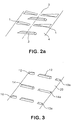
- FIG. 3 depicts a preferred orientation of embossings 10, 10a, 12, 14, 14a in accordance with the present invention.
- a first embossing row, 10, 10a, 12 is shown having a centrally located elongated positive embossment 12 and distal embossment 10, 10a at each end of the positive elongated embossment 12.
- At least one distal embossment 10a in the first embossing row is negative, that is, it extends from the sheet of the filter material in a direction opposite to that of embossments 10, 12, which are considered positive.
- a second embossing row having two elongated embossments 14, 14a is also formed and positioned at a location laterally spaced from embossments 10, 12, 10a.
- the alternating embossment segments avoid locations where an embossment transitions between negative and positive and thereby avoids the formation of bending lines or rotation points 2 as are present in the prior art configurations.
- At least one elongated embossment 14a is negative.
- FIG. 4a and 4b depict the first embossing row 1-a and the second embossing row 1-b, respectively.
- the first embossing row 1-a and the second embossing row 1-b extend parallel to each other along the material and the overlap of the various embossed segments prevents the formation of a rotation point as was formed in the material 4 of FIG. 1 .
- FIGS. 5 and 6 illustrate a portion of a filter in accordance with the present invention drawn through embossings 14, 14a.
- the filter media 20 according to the invention is formed from a filter fleece or non-woven cloth material, typically made from glass fiber and plastic fiber components or the like.
- Fold edge regions 30, 32 define walls 40 of material 20 therebetween, and embossing portions 14 and 14a are advantageously defined in a single plane, and the plane of embossing portions 14 and 14a is preferably oriented relative to the plane of walls 40 such that when material 20 is folded into the "V" pattern shown in FIGS. 5 and 6 , embossing portions 14 and 14a are substantially parallel to and equally spaced from embossing portions 14 and 14a of adjacent walls 40.
- Hot melt adhesive threads 32 are applied on both sides in the region of the embossings 14 and 14a. When folded to the position shown in FIGS. 5 and 6 , the hot melt adhesive threads 32 join together to form interconnected adhesive support portions.
- the mutually adjacent fold walls 40, after the adhesive 32 has set, are respectively clamped firmly in position on both sides, by virtue of those adhesive support portions 32, which is a substantial improvement over prior art configurations.
- FIG. 7 illustrates a portion of a filter in accordance with the present invention drawn through embossings 10, 12, 10a.
- the filter media 20 according to the invention is formed from a filter fleece or non-woven cloth material, typically made from glass fiber and plastic fiber components or the like.
- Fold edge regions 30, 32 define walls 40 of filter media 20 therebetween, and embossing portions 10, 10a, and 12 are advantageously defined in a single plane, and the plane of embossing portions 10, 10a, and 12 is preferably oriented relative to the plane of walls 40 such that when material 20 is folded into the "V" pattern shown in FIG. 7 , embossing portions 10, 10a, and 12 are substantially parallel to and equally spaced from embossing portions 10, 10a, and 12 of adjacent walls 40.
- Hot melt adhesive threads 34 are applied on both sides in the region of the embossing 10a alone and embossings 10 and 12 in conjunction. When folded to the position shown in FIG. 7 , the hot melt adhesive threads 34 join together to form interconnected adhesive support portions.
- the mutually adjacent fold walls 40, after the adhesive 34 has set, are respectively clamped firmly in position on both sides, by virtue of those adhesive support portions 34, which is a substantial improvement over prior art configurations.
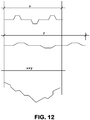
- FIG. 12 An additional undesirable bending or accordion effect is illustrated in FIG. 12 .
- the accordion effect contributes to the deformation of the pleat, which in turn increases the pressure drop of the filter due to the bad aerodynamics of a deformed (not a perfect V shaped) pleat.
- the views of FIG. 12 illustrate this undesirable bending, which can happen when embossings spread laterally as shown.
- x represents the ideal configuration of a cross section of embossings. See FIG. 10 section F12.
- pressure increases and the embossings begin to laterally spread, as illustrated by y.
- the pleated filter media 20 will begin to flatten and lose resistance to bending.
- the embossings will lose form, as illustrated by x+y.
- the pleats also will stretch and lose form, as shown in the third view of FIG. 12 .
- Intermediate embossings positioned according to the invention leave unembossed zones of material that help resist lateral spreading of the embossments, because the flat, non-embossed portion of material helps to resist the lateral spreading.
- the non-embossed portions are positioned so that, taken together, they define a diagonal line (See Figure 11 ) of embossing free filter media which helps to prevent stretching of the pleat and embossings.
- the configuration of the embossings according to the invention eliminates both rotation point 2 of FIG. 1 and the accordion effect of FIG. 12 .
- the filter portions shown in FIGS. 5-7 illustrate the orientation of the folded and glued filter media 20 as shown in FIGS. 3 and 11 .
- the configuration of the dimples eliminates the horizontal rotation point 2 by creating a more desirable diagonal line 40 of unembossed portions of filter media 20.
- This configuration of the unembossed to embossed portions of filter media 20 reduces the accordion effect, wherein the embossings rest upon one another to support the filter media 20 as air is forced through it.
- the main intermediate embossing 12 is both above and below diagonal 40. Intermediate embossing 12 is able to perform a double function. In order to sustain the pressure within the system, embossing 12 helps to keep the pleated filter media 20 as straight as possible and embossing 12 also helps to keep the accordion effect of material 20 to a minimum. Diagonal 40 helps to decrease the pressure flow through filter media 40 leading to less resistive aerodynamics through the system. The current design illustrated in FIGS. 3-7 reduces the pressure drop caused by deformation of the filter walls and thereby preserving the desired flow characteristics of the filter.
- FIGS. 5 through 7 show fold lines 30 for material 20, which are present along fold edges of material transverse to the embossings as shown for example in FIGS. 3 and 11 .
- the preferred orientation of embossing rows 1-a and 1-b provide that when folded, first embossing portions 1-a will face each other, and second embossing portions 1-b will also face each other.
- Embossing rows 1-a and 1-b are positioned substantially parallel to each other so as to facilitate application of adhesive to embossing rows 1-a and 1-b at a constant flow-rate of adhesive, which provides for a constant height or amount of adhesive per length as desired in accordance with the present invention.
- FIG. 13 depicts the filter media of the present invention with a plurality of intermediate embossings, i.e. positive embossments, negative embossments and combinations thereof. It has been found that an increase in the number of intermediate embossings will increase the strength of the filter material and decrease the bending of the walls due to force exerted on the filter material by the air pressure.
- FIG. 14 depicts the diagonal straight lines of non-embossed material that may be formed on filter media comprising a plurality of intermediate embossings. As shown, the intersecting diagonal lines of non-embossed material can provide a truss-like reinforcement to the wall to prevent accordion or spreading of the embossed portions.
- FIG. 15 depicts the placement of the glue on filter media comprising a plurality of intermediate embossings.
Landscapes
- Chemical & Material Sciences (AREA)
- Chemical Kinetics & Catalysis (AREA)
- Organic Chemistry (AREA)
- Filtering Of Dispersed Particles In Gases (AREA)
- Filtering Materials (AREA)
- Treatment Of Fiber Materials (AREA)
- Infusion, Injection, And Reservoir Apparatuses (AREA)
Claims (14)
- Flüssigkeitsfilterelement, umfassend:ein geprägtes flaches Filtermaterial (20), das zur Definierung einer Vielzahl von im Wesentlichen benachbarten Wänden (40) gefaltet ist, wobei jede Wand eine ebene Fläche zwischen zwei benachbarten Faltlinien definiert, wobei die Wand eine Prägung aufweist,umfassend:eine erste Prägungsreihe mit einer mittig angeordneten länglichen positiven Prägung (12) und jeweils eine distale Prägung (10, 10a) an den Enden der positiven länglichen Prägung, wobei mindestens eine distale Prägung negativ (10a) ist, d. h. sich von der Schicht des Filtermaterials in einer der Richtung der positiven Prägungen entgegengesetzten Richtung erstreckt; undeine zweite Prägungsreihe (14, 14a), die von der ersten Prägungsreihe beabstandet und parallel zu dieser ausgebildet ist,wobei die zweite Prägungsreihe zwei längliche Prägungen aufweist,wobei eine längliche Prägung negativ (14a) und eine längliche Prägung positiv (14) ist.
- Filterelement nach Anspruch 1, wobei entlang der ersten Prägungsreihe jeweils Zwischenräume zwischen der mittig angeordneten positiven Prägung und den distalen Prägungen definiert sind, wobei entlang der zweiten Prägungsreihe ein Zwischenraum zwischen den zwei länglichen Prägungen definiert ist und wobei die Zwischenräume der ersten Prägungsreihe nicht miteinander fluchten.
- Filterelement nach Anspruch 1, wobei die zweiten Prägungen (14, 14a) im Wesentlichen gleichmäßig beabstandet sind.
- Filterelement nach Anspruch 1, wobei die Wände Wandkanten definieren, die jeweils mindestens zwei Faltlinien aufweisen.
- Filterelement nach Anspruch 1, wobei die erste Prägungsreihe und die zweite Prägungsreihe abwechselnd ausgebildet sind.
- Filterelement nach Anspruch 1, wobei die erste Prägungsreihe und die zweite Prägungsreihe eine gerade diagonale Linie (40) aus prägungsfreiem Filtermaterial definieren.
- Filterelement nach Anspruch 1, wobei die erste Prägungsreihe des Weiteren eine Vielzahl von mittig angeordneten länglichen Prägungen umfasst, bei denen es sich wahlweise um positive Prägungen, negative Prägungen oder eine Kombination aus denselben handelt.
- Verfahren zur Ausbildung eines Flüssigkeitsfilterelements, umfassend die folgenden Schritte:Bereitstellen eines flachen Filtermaterials;Ausbilden einer Vielzahl von im Wesentlichen parallelen Prägungen in dem Material, wobei die Prägungen eine erste und eine zweite Prägungsreihe umfassen, die sich abwechseln;wobei die erste Prägungsreihe eine mittig angeordnete längliche positive Prägung und jeweils eine distale Prägung an den Enden der positiven länglichen Prägung aufweist, wobei mindestens eine distale Prägung negativ ist; unddie zweite Prägungsreihe von der ersten Prägungsreihe beabstandet und parallel zu dieser ausgebildet ist, wobei die zweite Prägungsreihe zwei längliche Prägungen aufweist, wobei eine längliche Prägung negativ und eine längliche Prägung positiv ist;Aufbringen eines Klebstoffes zumindest auf einen Abschnitt der Prägungen; undFalten des Materials in einem Zickzackmuster zur Definierung von Wänden des Materials, wobei jede Wand die erste und die zweite Prägungsreihe aufweist, die sich abwechseln, wobei der Klebstoff die Prägungen benachbarter Wände miteinander verklebt.
- Verfahren nach Anspruch 8, wobei entlang der ersten Prägungsreihe jeweils Zwischenräume zwischen der mittig angeordneten länglichen positiven Prägung und den distalen Prägungen definiert sind, wobei entlang der zweiten Prägungsreihe ein Zwischenraum zwischen den zwei länglichen Prägungen definiert ist und wobei die Zwischenräume der ersten Prägungsreihe nicht miteinander fluchten.
- Verfahren nach Anspruch 8, wobei die erste Prägungsreihe und die zweite Prägungsreihe eine gerade diagonale Linie aus prägungsfreiem Filtermaterial definieren.
- Verfahren nach Anspruch 8, wobei der Faltschritt die Wände so positioniert, dass Prägungen benachbarter Wände im Wesentlichen parallel sind.
- Verfahren nach Anspruch 8, wobei der Aufbringschritt das Aufbringen einer im Wesentlichen konstanten Menge Klebstoff pro Längeneinheit des Materials auf das Material umfasst.
- Verfahren nach Anspruch 8, wobei der Klebstoff in dem Aufbringschritt wahlweise als kontinuierlicher Strang, punktuell oder auf daraus kombinierte Weise aufgebracht wird.
- Verfahren nach Anspruch 8, wobei die erste Prägungsreihe des Weiteren eine Vielzahl von mittig angeordneten länglichen Prägungen umfasst, bei denen es sich wahlweise um positive Prägungen, negative Prägungen oder eine Kombination aus denselben handelt.
Applications Claiming Priority (2)
| Application Number | Priority Date | Filing Date | Title |
|---|---|---|---|
| US25283209P | 2009-10-19 | 2009-10-19 | |
| PCT/US2010/053153 WO2011049926A1 (en) | 2009-10-19 | 2010-10-19 | Embossed fluid filter element |
Publications (3)
| Publication Number | Publication Date |
|---|---|
| EP2490785A1 EP2490785A1 (de) | 2012-08-29 |
| EP2490785A4 EP2490785A4 (de) | 2016-12-28 |
| EP2490785B1 true EP2490785B1 (de) | 2018-05-30 |
Family
ID=43900639
Family Applications (1)
| Application Number | Title | Priority Date | Filing Date |
|---|---|---|---|
| EP10825507.6A Active EP2490785B1 (de) | 2009-10-19 | 2010-10-19 | Geprägtes flüssigkeitsfilterelement |
Country Status (8)
| Country | Link |
|---|---|
| US (2) | US9314717B2 (de) |
| EP (1) | EP2490785B1 (de) |
| JP (1) | JP5647691B2 (de) |
| KR (1) | KR101739734B1 (de) |
| CN (1) | CN102740944B (de) |
| AU (1) | AU2010308286B2 (de) |
| TR (1) | TR201811087T4 (de) |
| WO (1) | WO2011049926A1 (de) |
Families Citing this family (23)
| Publication number | Priority date | Publication date | Assignee | Title |
|---|---|---|---|---|
| CN102740944B (zh) * | 2009-10-19 | 2014-11-26 | Lpd科技公司 | 被压印的流体过滤元件 |
| JP5333550B2 (ja) * | 2011-08-31 | 2013-11-06 | ダイキン工業株式会社 | エアフィルタ用濾材及びエアフィルタユニット |
| JP2014064995A (ja) * | 2012-09-26 | 2014-04-17 | Japan Vilene Co Ltd | フィルタエレメント |
| US20140165839A1 (en) * | 2012-12-13 | 2014-06-19 | Clarcor Air Filtration Products, Inc. | Extended Life Panel Filter |
| US10040018B2 (en) | 2013-01-09 | 2018-08-07 | Imagine Tf, Llc | Fluid filters and methods of use |
| DE102013015645A1 (de) * | 2013-09-23 | 2015-03-26 | Mann + Hummel Gmbh | Vorrichtung und Verfahren zum Herstellen eines Filterbalgs |
| US9861920B1 (en) | 2015-05-01 | 2018-01-09 | Imagine Tf, Llc | Three dimensional nanometer filters and methods of use |
| FR3022153B1 (fr) * | 2014-06-12 | 2016-05-27 | Mecacorp | Procede et dispositif de fabrication d’un element filtrant pour filtre a air |
| US10730047B2 (en) | 2014-06-24 | 2020-08-04 | Imagine Tf, Llc | Micro-channel fluid filters and methods of use |
| US10124275B2 (en) | 2014-09-05 | 2018-11-13 | Imagine Tf, Llc | Microstructure separation filters |
| DE102014117506A1 (de) * | 2014-11-28 | 2016-06-02 | Filta Co., Ltd | Filtermedium mit großem Faltenabstand |
| WO2016133929A1 (en) | 2015-02-18 | 2016-08-25 | Imagine Tf, Llc | Three dimensional filter devices and apparatuses |
| US10118842B2 (en) | 2015-07-09 | 2018-11-06 | Imagine Tf, Llc | Deionizing fluid filter devices and methods of use |
| US10479046B2 (en) | 2015-08-19 | 2019-11-19 | Imagine Tf, Llc | Absorbent microstructure arrays and methods of use |
| CN110167654B (zh) * | 2016-06-24 | 2022-08-26 | K&N工程公司 | 复合式空气过滤器 |
| JP6399069B2 (ja) * | 2016-09-30 | 2018-10-03 | ダイキン工業株式会社 | エアフィルタ濾材、エアフィルタパック、およびエアフィルタユニット |
| EP3529111B1 (de) * | 2016-10-20 | 2023-01-11 | Cummins Filtration IP, Inc. | Unterbrochene, direktionale prägung einer flachen platte |
| CN107158842A (zh) * | 2017-05-25 | 2017-09-15 | 江苏人和环保设备有限公司 | 一种具有滤材褶面凹陷部的空气滤芯 |
| JP7688019B2 (ja) | 2019-08-26 | 2025-06-03 | パーカー-ハネフィン コーポレーション | 構造的エンボス加工を使用する燃料水分離の強化 |
| EP4021612A4 (de) * | 2019-08-26 | 2023-03-15 | Parker-Hannifin Corporation | Filterelement und zugehörige filtermedien zur kraftstoff-wasser-trennung durch oberflächenprägung |
| KR102523443B1 (ko) * | 2021-07-28 | 2023-04-20 | 한명옥 | 여과율이 향상된 렌즈 연마수 여과 장치 |
| CN114733282A (zh) * | 2022-04-24 | 2022-07-12 | 廊坊坤合过滤器材有限公司 | 一种折叠式天然气滤芯 |
| US11638893B1 (en) | 2022-12-29 | 2023-05-02 | Filtration Advice, Inc. | Reinforced air filter |
Family Cites Families (22)
| Publication number | Priority date | Publication date | Assignee | Title |
|---|---|---|---|---|
| US2945559A (en) * | 1958-03-12 | 1960-07-19 | Gen Motors Corp | Filters for fluids |
| JPS61115126A (ja) | 1984-11-12 | 1986-06-02 | Toshiba Corp | 磁気デイスク装置 |
| JPS61115126U (de) * | 1984-12-27 | 1986-07-21 | ||
| ATE98892T1 (de) * | 1989-01-05 | 1994-01-15 | Camfil Ab | Filter. |
| US5028331A (en) * | 1989-02-08 | 1991-07-02 | Lippold Hans Joachim | Filter cartridge |
| WO1995017943A2 (de) | 1993-12-30 | 1995-07-06 | Detroit Holding Limited | Filtereinsatz und verfahren zu dessen herstellung |
| JP3001408B2 (ja) * | 1996-02-19 | 2000-01-24 | ニッタ株式会社 | エアフィルタ用濾材及びエアフィルタ用濾材の成形装置 |
| FR2774925B3 (fr) * | 1998-02-17 | 2000-04-14 | Filtrauto | Cartouche de filtration, notamment pour moteur a combustion interne |
| DE10015951C2 (de) | 1999-12-22 | 2002-09-26 | Jacobi Systemtechnik Gmbh | Filterelement |
| DK1414540T3 (da) * | 2000-09-21 | 2007-04-02 | Lpd Technologies Inc | Fluidumfilterelement |
| JP3688206B2 (ja) | 2001-02-07 | 2005-08-24 | 富士通日立プラズマディスプレイ株式会社 | プラズマディスプレイパネルの駆動方法および表示装置 |
| US6824581B1 (en) * | 2001-05-01 | 2004-11-30 | Dana Corporation | Pleated filter media with embossed spacers and cross flow |
| JP2003196807A (ja) | 2001-12-25 | 2003-07-11 | Hitachi Ltd | 磁気抵抗効果ヘッドおよびその製造方法 |
| JP4139121B2 (ja) | 2002-03-28 | 2008-08-27 | 日本無機株式会社 | ジグザグ状エアフィルタ用濾材の製造方法 |
| JP4733340B2 (ja) | 2003-04-24 | 2011-07-27 | 日本エアー・フィルター株式会社 | 折込み型エアフィルタ及びその製造方法 |
| US7661540B2 (en) * | 2003-12-30 | 2010-02-16 | Aaf Mcquay, Inc. | Method of forming spaced pleated filter material and product of same |
| US7425227B1 (en) * | 2004-06-17 | 2008-09-16 | Wix Filtration Corp Llc | Pleated filter element with offset emboss pattern |
| US20060180398A1 (en) | 2005-02-07 | 2006-08-17 | Ibrahim Khalil | Integrated waffle pan apparatus and method |
| US20080067121A1 (en) * | 2006-09-15 | 2008-03-20 | Lpd Technologies, Inc. | Fluid filter element with reinforcing scrim |
| US7588619B2 (en) * | 2006-11-28 | 2009-09-15 | Wix Filtration Corp. | Cross-flow filter media and filter assembly |
| JP4906762B2 (ja) | 2008-03-17 | 2012-03-28 | キヤノン株式会社 | 印刷装置及び印刷装置の制御方法 |
| CN102740944B (zh) * | 2009-10-19 | 2014-11-26 | Lpd科技公司 | 被压印的流体过滤元件 |
-
2010
- 2010-10-19 CN CN201080057869.XA patent/CN102740944B/zh active Active
- 2010-10-19 KR KR1020127012899A patent/KR101739734B1/ko active Active
- 2010-10-19 WO PCT/US2010/053153 patent/WO2011049926A1/en not_active Ceased
- 2010-10-19 EP EP10825507.6A patent/EP2490785B1/de active Active
- 2010-10-19 JP JP2012535294A patent/JP5647691B2/ja active Active
- 2010-10-19 AU AU2010308286A patent/AU2010308286B2/en active Active
- 2010-10-19 TR TR2018/11087T patent/TR201811087T4/tr unknown
- 2010-10-19 US US13/502,755 patent/US9314717B2/en active Active
-
2016
- 2016-03-23 US US15/077,971 patent/US10143951B2/en active Active
Non-Patent Citations (1)
| Title |
|---|
| None * |
Also Published As
| Publication number | Publication date |
|---|---|
| US9314717B2 (en) | 2016-04-19 |
| WO2011049926A1 (en) | 2011-04-28 |
| AU2010308286A1 (en) | 2012-05-17 |
| US20160243481A1 (en) | 2016-08-25 |
| TR201811087T4 (tr) | 2018-08-27 |
| JP2013508143A (ja) | 2013-03-07 |
| US10143951B2 (en) | 2018-12-04 |
| KR20120085818A (ko) | 2012-08-01 |
| AU2010308286B2 (en) | 2015-10-29 |
| CN102740944B (zh) | 2014-11-26 |
| JP5647691B2 (ja) | 2015-01-07 |
| CN102740944A (zh) | 2012-10-17 |
| US20120261331A1 (en) | 2012-10-18 |
| KR101739734B1 (ko) | 2017-05-25 |
| EP2490785A1 (de) | 2012-08-29 |
| EP2490785A4 (de) | 2016-12-28 |
Similar Documents
| Publication | Publication Date | Title |
|---|---|---|
| EP2490785B1 (de) | Geprägtes flüssigkeitsfilterelement | |
| KR102331811B1 (ko) | 여과 매체, 주름형 매체 팩, 필터 카트리지, 및 제조 방법 | |
| EP1414540B1 (de) | Fluidfilterelement | |
| CA2859155C (en) | Nestable framed pleated air filter and method of making | |
| CA2859137C (en) | Framed pleated air filter with upstream bridging filaments | |
| JPH06339611A (ja) | フィルタ | |
| WO2002055179A1 (de) | Herstellungsverfahren für plissierbare filter und verfahrenserzeugnisse | |
| CN105026014B (zh) | 带有调制波纹的波纹状过滤介质 | |
| US20150273383A1 (en) | Strip, fiter with the strip, method and apparatus for producing the strip | |
| US20170001138A1 (en) | Filter Element with Filter Bellows | |
| CA2335053A1 (en) | Folded filter | |
| WO1999026711A1 (en) | Filter with form-retaining stabilizing means | |
| JP2025542501A (ja) | 補強される空気濾過器 | |
| KR20140074859A (ko) | 종이 필터를 구비한 필터링 장치 | |
| JP2012139651A (ja) | フィルタエレメント | |
| CN106714935A (zh) | 具有过滤波纹包的过滤元件 | |
| WO2024211675A1 (en) | Air filter with different diameter glue beads | |
| JP2001327808A (ja) | フィルター |
Legal Events
| Date | Code | Title | Description |
|---|---|---|---|
| PUAI | Public reference made under article 153(3) epc to a published international application that has entered the european phase |
Free format text: ORIGINAL CODE: 0009012 |
|
| 17P | Request for examination filed |
Effective date: 20120419 |
|
| AK | Designated contracting states |
Kind code of ref document: A1 Designated state(s): AL AT BE BG CH CY CZ DE DK EE ES FI FR GB GR HR HU IE IS IT LI LT LU LV MC MK MT NL NO PL PT RO RS SE SI SK SM TR |
|
| DAX | Request for extension of the european patent (deleted) | ||
| RA4 | Supplementary search report drawn up and despatched (corrected) |
Effective date: 20161124 |
|
| RIC1 | Information provided on ipc code assigned before grant |
Ipc: B01D 46/10 20060101ALI20161118BHEP Ipc: B01D 46/00 20060101ALI20161118BHEP Ipc: B01D 46/52 20060101ALI20161118BHEP Ipc: B01D 29/21 20060101AFI20161118BHEP Ipc: B01D 29/01 20060101ALI20161118BHEP Ipc: C09J 5/02 20060101ALI20161118BHEP Ipc: B01D 29/11 20060101ALI20161118BHEP |
|
| GRAP | Despatch of communication of intention to grant a patent |
Free format text: ORIGINAL CODE: EPIDOSNIGR1 |
|
| INTG | Intention to grant announced |
Effective date: 20180108 |
|
| RIC1 | Information provided on ipc code assigned before grant |
Ipc: B01D 46/00 20060101ALI20171215BHEP Ipc: B01D 46/10 20060101ALI20171215BHEP Ipc: B01D 46/52 20060101ALI20171215BHEP Ipc: C09J 5/02 20060101ALI20171215BHEP Ipc: B01D 29/01 20060101ALI20171215BHEP Ipc: B01D 29/21 20060101AFI20171215BHEP Ipc: B01D 29/11 20060101ALI20171215BHEP |
|
| GRAS | Grant fee paid |
Free format text: ORIGINAL CODE: EPIDOSNIGR3 |
|
| GRAA | (expected) grant |
Free format text: ORIGINAL CODE: 0009210 |
|
| AK | Designated contracting states |
Kind code of ref document: B1 Designated state(s): AL AT BE BG CH CY CZ DE DK EE ES FI FR GB GR HR HU IE IS IT LI LT LU LV MC MK MT NL NO PL PT RO RS SE SI SK SM TR |
|
| REG | Reference to a national code |
Ref country code: GB Ref legal event code: FG4D |
|
| REG | Reference to a national code |
Ref country code: CH Ref legal event code: EP |
|
| REG | Reference to a national code |
Ref country code: AT Ref legal event code: REF Ref document number: 1003034 Country of ref document: AT Kind code of ref document: T Effective date: 20180615 |
|
| REG | Reference to a national code |
Ref country code: IE Ref legal event code: FG4D |
|
| REG | Reference to a national code |
Ref country code: DE Ref legal event code: R096 Ref document number: 602010051018 Country of ref document: DE |
|
| REG | Reference to a national code |
Ref country code: SE Ref legal event code: TRGR |
|
| REG | Reference to a national code |
Ref country code: NL Ref legal event code: FP |
|
| REG | Reference to a national code |
Ref country code: LT Ref legal event code: MG4D |
|
| REG | Reference to a national code |
Ref country code: FR Ref legal event code: PLFP Year of fee payment: 9 |
|
| PG25 | Lapsed in a contracting state [announced via postgrant information from national office to epo] |
Ref country code: ES Free format text: LAPSE BECAUSE OF FAILURE TO SUBMIT A TRANSLATION OF THE DESCRIPTION OR TO PAY THE FEE WITHIN THE PRESCRIBED TIME-LIMIT Effective date: 20180530 Ref country code: LT Free format text: LAPSE BECAUSE OF FAILURE TO SUBMIT A TRANSLATION OF THE DESCRIPTION OR TO PAY THE FEE WITHIN THE PRESCRIBED TIME-LIMIT Effective date: 20180530 Ref country code: CY Free format text: LAPSE BECAUSE OF FAILURE TO SUBMIT A TRANSLATION OF THE DESCRIPTION OR TO PAY THE FEE WITHIN THE PRESCRIBED TIME-LIMIT Effective date: 20180530 Ref country code: FI Free format text: LAPSE BECAUSE OF FAILURE TO SUBMIT A TRANSLATION OF THE DESCRIPTION OR TO PAY THE FEE WITHIN THE PRESCRIBED TIME-LIMIT Effective date: 20180530 Ref country code: BG Free format text: LAPSE BECAUSE OF FAILURE TO SUBMIT A TRANSLATION OF THE DESCRIPTION OR TO PAY THE FEE WITHIN THE PRESCRIBED TIME-LIMIT Effective date: 20180830 Ref country code: NO Free format text: LAPSE BECAUSE OF FAILURE TO SUBMIT A TRANSLATION OF THE DESCRIPTION OR TO PAY THE FEE WITHIN THE PRESCRIBED TIME-LIMIT Effective date: 20180830 |
|
| PG25 | Lapsed in a contracting state [announced via postgrant information from national office to epo] |
Ref country code: GR Free format text: LAPSE BECAUSE OF FAILURE TO SUBMIT A TRANSLATION OF THE DESCRIPTION OR TO PAY THE FEE WITHIN THE PRESCRIBED TIME-LIMIT Effective date: 20180831 Ref country code: LV Free format text: LAPSE BECAUSE OF FAILURE TO SUBMIT A TRANSLATION OF THE DESCRIPTION OR TO PAY THE FEE WITHIN THE PRESCRIBED TIME-LIMIT Effective date: 20180530 Ref country code: RS Free format text: LAPSE BECAUSE OF FAILURE TO SUBMIT A TRANSLATION OF THE DESCRIPTION OR TO PAY THE FEE WITHIN THE PRESCRIBED TIME-LIMIT Effective date: 20180530 Ref country code: HR Free format text: LAPSE BECAUSE OF FAILURE TO SUBMIT A TRANSLATION OF THE DESCRIPTION OR TO PAY THE FEE WITHIN THE PRESCRIBED TIME-LIMIT Effective date: 20180530 |
|
| PG25 | Lapsed in a contracting state [announced via postgrant information from national office to epo] |
Ref country code: CZ Free format text: LAPSE BECAUSE OF FAILURE TO SUBMIT A TRANSLATION OF THE DESCRIPTION OR TO PAY THE FEE WITHIN THE PRESCRIBED TIME-LIMIT Effective date: 20180530 Ref country code: SK Free format text: LAPSE BECAUSE OF FAILURE TO SUBMIT A TRANSLATION OF THE DESCRIPTION OR TO PAY THE FEE WITHIN THE PRESCRIBED TIME-LIMIT Effective date: 20180530 Ref country code: PL Free format text: LAPSE BECAUSE OF FAILURE TO SUBMIT A TRANSLATION OF THE DESCRIPTION OR TO PAY THE FEE WITHIN THE PRESCRIBED TIME-LIMIT Effective date: 20180530 Ref country code: RO Free format text: LAPSE BECAUSE OF FAILURE TO SUBMIT A TRANSLATION OF THE DESCRIPTION OR TO PAY THE FEE WITHIN THE PRESCRIBED TIME-LIMIT Effective date: 20180530 Ref country code: DK Free format text: LAPSE BECAUSE OF FAILURE TO SUBMIT A TRANSLATION OF THE DESCRIPTION OR TO PAY THE FEE WITHIN THE PRESCRIBED TIME-LIMIT Effective date: 20180530 Ref country code: EE Free format text: LAPSE BECAUSE OF FAILURE TO SUBMIT A TRANSLATION OF THE DESCRIPTION OR TO PAY THE FEE WITHIN THE PRESCRIBED TIME-LIMIT Effective date: 20180530 |
|
| PG25 | Lapsed in a contracting state [announced via postgrant information from national office to epo] |
Ref country code: SM Free format text: LAPSE BECAUSE OF FAILURE TO SUBMIT A TRANSLATION OF THE DESCRIPTION OR TO PAY THE FEE WITHIN THE PRESCRIBED TIME-LIMIT Effective date: 20180530 Ref country code: IT Free format text: LAPSE BECAUSE OF FAILURE TO SUBMIT A TRANSLATION OF THE DESCRIPTION OR TO PAY THE FEE WITHIN THE PRESCRIBED TIME-LIMIT Effective date: 20180530 |
|
| REG | Reference to a national code |
Ref country code: DE Ref legal event code: R097 Ref document number: 602010051018 Country of ref document: DE |
|
| PLBE | No opposition filed within time limit |
Free format text: ORIGINAL CODE: 0009261 |
|
| STAA | Information on the status of an ep patent application or granted ep patent |
Free format text: STATUS: NO OPPOSITION FILED WITHIN TIME LIMIT |
|
| 26N | No opposition filed |
Effective date: 20190301 |
|
| PG25 | Lapsed in a contracting state [announced via postgrant information from national office to epo] |
Ref country code: SI Free format text: LAPSE BECAUSE OF FAILURE TO SUBMIT A TRANSLATION OF THE DESCRIPTION OR TO PAY THE FEE WITHIN THE PRESCRIBED TIME-LIMIT Effective date: 20180530 |
|
| PG25 | Lapsed in a contracting state [announced via postgrant information from national office to epo] |
Ref country code: MC Free format text: LAPSE BECAUSE OF FAILURE TO SUBMIT A TRANSLATION OF THE DESCRIPTION OR TO PAY THE FEE WITHIN THE PRESCRIBED TIME-LIMIT Effective date: 20180530 Ref country code: LU Free format text: LAPSE BECAUSE OF NON-PAYMENT OF DUE FEES Effective date: 20181019 |
|
| PG25 | Lapsed in a contracting state [announced via postgrant information from national office to epo] |
Ref country code: AL Free format text: LAPSE BECAUSE OF FAILURE TO SUBMIT A TRANSLATION OF THE DESCRIPTION OR TO PAY THE FEE WITHIN THE PRESCRIBED TIME-LIMIT Effective date: 20180530 |
|
| PG25 | Lapsed in a contracting state [announced via postgrant information from national office to epo] |
Ref country code: MT Free format text: LAPSE BECAUSE OF NON-PAYMENT OF DUE FEES Effective date: 20181019 |
|
| PG25 | Lapsed in a contracting state [announced via postgrant information from national office to epo] |
Ref country code: PT Free format text: LAPSE BECAUSE OF FAILURE TO SUBMIT A TRANSLATION OF THE DESCRIPTION OR TO PAY THE FEE WITHIN THE PRESCRIBED TIME-LIMIT Effective date: 20180530 |
|
| PG25 | Lapsed in a contracting state [announced via postgrant information from national office to epo] |
Ref country code: MK Free format text: LAPSE BECAUSE OF NON-PAYMENT OF DUE FEES Effective date: 20180530 Ref country code: HU Free format text: LAPSE BECAUSE OF FAILURE TO SUBMIT A TRANSLATION OF THE DESCRIPTION OR TO PAY THE FEE WITHIN THE PRESCRIBED TIME-LIMIT; INVALID AB INITIO Effective date: 20101019 |
|
| PG25 | Lapsed in a contracting state [announced via postgrant information from national office to epo] |
Ref country code: IS Free format text: LAPSE BECAUSE OF FAILURE TO SUBMIT A TRANSLATION OF THE DESCRIPTION OR TO PAY THE FEE WITHIN THE PRESCRIBED TIME-LIMIT Effective date: 20180930 |
|
| REG | Reference to a national code |
Ref country code: AT Ref legal event code: UEP Ref document number: 1003034 Country of ref document: AT Kind code of ref document: T Effective date: 20180530 |
|
| REG | Reference to a national code |
Ref country code: CH Ref legal event code: U11 Free format text: ST27 STATUS EVENT CODE: U-0-0-U10-U11 (AS PROVIDED BY THE NATIONAL OFFICE) Effective date: 20251101 |
|
| PGFP | Annual fee paid to national office [announced via postgrant information from national office to epo] |
Ref country code: NL Payment date: 20251026 Year of fee payment: 16 |
|
| PGFP | Annual fee paid to national office [announced via postgrant information from national office to epo] |
Ref country code: DE Payment date: 20251029 Year of fee payment: 16 |
|
| PGFP | Annual fee paid to national office [announced via postgrant information from national office to epo] |
Ref country code: GB Payment date: 20251027 Year of fee payment: 16 |
|
| PGFP | Annual fee paid to national office [announced via postgrant information from national office to epo] |
Ref country code: AT Payment date: 20251029 Year of fee payment: 16 |
|
| PGFP | Annual fee paid to national office [announced via postgrant information from national office to epo] |
Ref country code: FR Payment date: 20251027 Year of fee payment: 16 |
|
| PGFP | Annual fee paid to national office [announced via postgrant information from national office to epo] |
Ref country code: TR Payment date: 20251007 Year of fee payment: 16 Ref country code: BE Payment date: 20251027 Year of fee payment: 16 |
|
| PGFP | Annual fee paid to national office [announced via postgrant information from national office to epo] |
Ref country code: SE Payment date: 20251027 Year of fee payment: 16 Ref country code: CH Payment date: 20251101 Year of fee payment: 16 |
|
| PGFP | Annual fee paid to national office [announced via postgrant information from national office to epo] |
Ref country code: IE Payment date: 20251027 Year of fee payment: 16 |