EP2490512A1 - High-frequency accelerator, method for manufacturing high-frequency accelerator, quadrupole accelerator, and method for manufacturing quadrupole accelerator - Google Patents
High-frequency accelerator, method for manufacturing high-frequency accelerator, quadrupole accelerator, and method for manufacturing quadrupole accelerator Download PDFInfo
- Publication number
- EP2490512A1 EP2490512A1 EP10823496A EP10823496A EP2490512A1 EP 2490512 A1 EP2490512 A1 EP 2490512A1 EP 10823496 A EP10823496 A EP 10823496A EP 10823496 A EP10823496 A EP 10823496A EP 2490512 A1 EP2490512 A1 EP 2490512A1
- Authority
- EP
- European Patent Office
- Prior art keywords
- members
- accelerator
- radio frequency
- outer frame
- tubular part
- Prior art date
- Legal status (The legal status is an assumption and is not a legal conclusion. Google has not performed a legal analysis and makes no representation as to the accuracy of the status listed.)
- Withdrawn
Links
- 238000000034 method Methods 0.000 title claims abstract description 78
- 238000004519 manufacturing process Methods 0.000 title claims abstract description 77
- 230000001133 acceleration Effects 0.000 claims abstract description 129
- 238000003466 welding Methods 0.000 claims abstract description 91
- 238000003756 stirring Methods 0.000 claims abstract description 50
- 239000002245 particle Substances 0.000 claims description 26
- 238000002360 preparation method Methods 0.000 claims description 24
- 230000003014 reinforcing effect Effects 0.000 claims description 20
- 230000003746 surface roughness Effects 0.000 claims description 19
- 238000003825 pressing Methods 0.000 claims description 5
- 238000007789 sealing Methods 0.000 description 11
- 238000005219 brazing Methods 0.000 description 8
- 230000005684 electric field Effects 0.000 description 8
- 239000000463 material Substances 0.000 description 8
- 229910052782 aluminium Inorganic materials 0.000 description 6
- XAGFODPZIPBFFR-UHFFFAOYSA-N aluminium Chemical compound [Al] XAGFODPZIPBFFR-UHFFFAOYSA-N 0.000 description 6
- 238000013461 design Methods 0.000 description 6
- 229910052751 metal Inorganic materials 0.000 description 6
- 239000002184 metal Substances 0.000 description 6
- 238000005520 cutting process Methods 0.000 description 5
- 230000005672 electromagnetic field Effects 0.000 description 5
- 238000005498 polishing Methods 0.000 description 5
- 238000010894 electron beam technology Methods 0.000 description 4
- 238000000227 grinding Methods 0.000 description 4
- 238000002347 injection Methods 0.000 description 4
- 239000007924 injection Substances 0.000 description 4
- 238000005304 joining Methods 0.000 description 4
- RYGMFSIKBFXOCR-UHFFFAOYSA-N Copper Chemical compound [Cu] RYGMFSIKBFXOCR-UHFFFAOYSA-N 0.000 description 3
- 238000001816 cooling Methods 0.000 description 3
- 229910052802 copper Inorganic materials 0.000 description 3
- 239000010949 copper Substances 0.000 description 3
- 238000000605 extraction Methods 0.000 description 3
- 238000012545 processing Methods 0.000 description 3
- 239000003990 capacitor Substances 0.000 description 2
- 239000000498 cooling water Substances 0.000 description 2
- 230000002500 effect on skin Effects 0.000 description 2
- 230000000694 effects Effects 0.000 description 2
- 239000000945 filler Substances 0.000 description 2
- 238000003754 machining Methods 0.000 description 2
- 238000010002 mechanical finishing Methods 0.000 description 2
- 150000002739 metals Chemical class 0.000 description 2
- 241000220317 Rosa Species 0.000 description 1
- 238000013459 approach Methods 0.000 description 1
- 239000011324 bead Substances 0.000 description 1
- 230000015572 biosynthetic process Effects 0.000 description 1
- 239000004020 conductor Substances 0.000 description 1
- 238000012790 confirmation Methods 0.000 description 1
- 230000008602 contraction Effects 0.000 description 1
- 239000002826 coolant Substances 0.000 description 1
- 230000001419 dependent effect Effects 0.000 description 1
- 230000002542 deteriorative effect Effects 0.000 description 1
- 150000002500 ions Chemical class 0.000 description 1
- 230000013011 mating Effects 0.000 description 1
- 230000035515 penetration Effects 0.000 description 1
- 239000000243 solution Substances 0.000 description 1
- 238000000638 solvent extraction Methods 0.000 description 1
- 229910001220 stainless steel Inorganic materials 0.000 description 1
- 239000010935 stainless steel Substances 0.000 description 1
Images






Classifications
-
- H—ELECTRICITY
- H05—ELECTRIC TECHNIQUES NOT OTHERWISE PROVIDED FOR
- H05H—PLASMA TECHNIQUE; PRODUCTION OF ACCELERATED ELECTRICALLY-CHARGED PARTICLES OR OF NEUTRONS; PRODUCTION OR ACCELERATION OF NEUTRAL MOLECULAR OR ATOMIC BEAMS
- H05H7/00—Details of devices of the types covered by groups H05H9/00, H05H11/00, H05H13/00
- H05H7/22—Details of linear accelerators, e.g. drift tubes
-
- H—ELECTRICITY
- H05—ELECTRIC TECHNIQUES NOT OTHERWISE PROVIDED FOR
- H05H—PLASMA TECHNIQUE; PRODUCTION OF ACCELERATED ELECTRICALLY-CHARGED PARTICLES OR OF NEUTRONS; PRODUCTION OR ACCELERATION OF NEUTRAL MOLECULAR OR ATOMIC BEAMS
- H05H9/00—Linear accelerators
- H05H9/04—Standing-wave linear accelerators
- H05H9/041—Hadron LINACS
- H05H9/045—Radio frequency quadrupoles
-
- Y—GENERAL TAGGING OF NEW TECHNOLOGICAL DEVELOPMENTS; GENERAL TAGGING OF CROSS-SECTIONAL TECHNOLOGIES SPANNING OVER SEVERAL SECTIONS OF THE IPC; TECHNICAL SUBJECTS COVERED BY FORMER USPC CROSS-REFERENCE ART COLLECTIONS [XRACs] AND DIGESTS
- Y10—TECHNICAL SUBJECTS COVERED BY FORMER USPC
- Y10T—TECHNICAL SUBJECTS COVERED BY FORMER US CLASSIFICATION
- Y10T29/00—Metal working
- Y10T29/49—Method of mechanical manufacture
- Y10T29/49002—Electrical device making
- Y10T29/49117—Conductor or circuit manufacturing
Definitions
- the present invention relates to a radio frequency accelerator, a method of production of a radio frequency accelerator, a radio frequency quadrupole accelerator, and a method of production of a radio frequency quadrupole accelerator.
- a radio frequency accelerator for accelerating ions, electrons, or other charged particles.
- a radio frequency accelerator is provided inside it with an acceleration cavity for accelerating charged particles.
- the acceleration cavity forms a resonance circuit and has a unique resonance frequency.
- a radio frequency accelerator can accelerate charged particles up to a desired energy by injecting charged particles at a predetermined timing in the state where the radio frequency electric field is excited.
- Radio frequency accelerators are classified by the shape of the path of the charged particles into linear accelerators (linacs) and circular accelerators.
- Linear accelerator is accelerator with straight paths of the charged particle beam
- circular accelerators are accelerators with curved paths of the charged particle beam.
- Linear accelerators include, for example, radio frequency quadrupole accelerators, drift tube accelerators, etc.
- a radio frequency quadrupole accelerator is provided with four electrodes.
- the four electrodes form two mutually facing pairs.
- wave shapes suitable for acceleration of a beam are formed in the direction of the acceleration beam axis.
- an electric field is formed for accelerating and focusing a beam. By injecting charged particles into this space, the charged particles are accelerated.
- Japanese Patent Publication (A) No. 5-62798 discloses an external resonance type quadrupole particle accelerator which is provided with an accelerator tube which has electrodes forming the quadrupole structure inside of it and a radio frequency resonance circuit which supplies a resonance voltage to the electrodes.
- This publication discloses the radio frequency resonance circuit being comprised of a capacitor and two coil conductors serving as an inductance member and the inductance member being arranged in series between the capacitor and the accelerator. According to this accelerator, the resonance frequency can be made to change over a broad range and, further, the quality factor can be raised.
- the indicators which show the electrical performance of an accelerator include the "quality factor".
- the indicators which shown the electrical performance of a radio frequency quadrupole accelerator also include the quality factor.
- the quality factor is proportional to the value of the energy which is stored inside of the cavity at the time of operation of the accelerator divided by the power loss. The larger the quality factor, the longer the operating time per unit energy and the better the operating efficiency.
- the acceleration cavity has an electrical resistance based on the shape, material, etc. Power is consumed in accordance with the magnitude of this electrical resistance. If the electrical resistance is large, the power consumption becomes larger and the quality factor becomes lower. The electrical resistance changes due to the surface roughness at the inside surface of the acceleration cavity as well and, as a result, the quality factor changes. The smaller the surface roughness of the inside surface of acceleration cavity, the higher the quality factor.
- a plurality of component members are formed in advance and then the plurality of component members are joined together to form an acceleration cavity.
- the step of forming the plurality of component members it is possible to manufacture component members which are high in dimensional precision and further are small in surface roughness. For example, by cutting with a high precision, it is possible to manufacture component members with a high dimensional precision. Further, it is possible to grind or polish the surfaces of the component members in various ways so as to reduce the surface roughness.
- an acceleration cavity has a unique resonance frequency.
- the resonance frequency depends on the shape of the acceleration cavity.
- the resonance frequency greatly depends on the shape in the extent that the resonance frequency is affected by the heat expansion or heat contraction in micron units due to temperature changes of the acceleration cavity. For this reason, the resonance frequency greatly depends on the precision of fabrication. In the manufacture of an accelerator cavity, preferably the cavity is produced with dimensions matching the design values.
- the present invention provides a radio frequency accelerator and a radio frequency quadrupole accelerator which are excellent in electrical performance and easy to manufacture and a method of production of the radio frequency accelerator and method of production of the radio frequency quadrupole accelerator.
- a method of production of a radio frequency accelerator of the present invention provides a method of production of a radio frequency accelerator which has a tubular part which forms an acceleration cavity and which has electrodes arranged inside of the tubular part, including a preparation step of preparing a plurality of component members which have shapes obtained by splitting the tubular part, a temporary assembly step of making the plurality of component members mate with each other to temporarily assemble them into the shape of the tubular part, a step of fastening a temporarily assembled tubular part by pressing it from the outer side, and a welding step of welding the plurality of component members together.
- the temporary assembly step includes a step of placing, inside of the tubular part, support members for contacting the inside surface of the tubular part and supporting the tubular part from the inside, and the welding step includes a step of welding the plurality of component members along the butt lines by friction stir welding.
- the plurality of component members are formed with cutaway parts at the regions for friction stir welding, and the method includes a step of attaching reinforcing members which have shapes which engage with the cutaway parts after the welding step.
- the method may be a method of production of an accelerator which is provided with four electrodes which stick out from the tubular part toward the acceleration beam axis of the charged particles, where the plurality of component members have shapes obtained by splitting the tubular part near the bottom parts of the electrodes and where the temporary assembly step includes a step of arranging support members which contact butt lines of the plurality of component members and extend along the acceleration beam axis.
- the preparation step prepares component members comprised of members which form the tubular part and electrodes which are formed seamlessly.
- the radio frequency accelerator of the present invention is provided with a tubular part which forms an acceleration cavity and which includes a plurality of component members, at least one component member among the plurality of component members includes an electrode, the plurality of component members are welded with each other through joints which are formed by friction stir welding, the joints are formed with stripe-shaped weld marks at outer surfaces, and a surface roughness of the inner surfaces is smaller than a surface roughness at the outer surfaces.
- the tubular part has cutaway parts which are formed at regions of the joints of the friction stir welding and the radio frequency accelerator is further provided with reinforcing members which are engaged with the cutaway parts to be fastened to the component members.
- the radio frequency quadrupole accelerator of the present invention is provided with a center member which includes a center outer frame part, a first electrode which sticks out from the center outer frame part toward the inside, and a second electrode which sticks out from the center outer frame part toward the inside, a first side member which includes a first side outer frame part, a first wall part which extends from the first side outer frame part toward the outside and which has the shape of part of an acceleration cavity, and a third electrode which sticks out from the first wall part toward the inside and which is arranged at one side of the center member, and a second side member which includes a second side outer frame part, a second wall part which extends from the second side outer frame part toward the outside and which has the shape of part of an acceleration cavity, and a fourth electrode which sticks out from the second wall part toward the inside and which is arranged at the other side of the center member.
- the center member, the first side member, and the second side member are respectively formed seamlessly from single members.
- the center member, the first side member, and the second side member are configured so that the center outer frame part, the first side outer frame part, and the second side outer frame part are fastened by fastening members.
- the center member, the first side member, and the second side member are fastened with each other through conductive members.
- a method of production of a radio frequency quadrupole accelerator of the present invention includes a member preparation step which prepares a center member which includes a center outer frame part, a first electrode which sticks out from the center outer frame part and a second electrode which sticks out from the center outer frame part, a first side member which includes a first side outer frame part, a first wall part which has the shape of part of an acceleration cavity, and a third electrode which sticks out from the first wall part, and a second side member which includes a second side outer frame part, a second wall part which has the shape of part of an acceleration cavity, and a fourth electrode which sticks out from the second wall part, and an assembly step of arranging the first side member and the second side member at the both sides of the center member and fastening the center outer frame part, first side outer frame part, and second side outer frame part with each other by fastening members.
- the member preparation step includes a step of respectively forming the center member, first side member, and second side member seamlessly from single members.
- the member preparation step includes a step of forming reference marks at an outer surface of the center member and a step of forming positioning marks at the outer surface of the first side member and the outer surface of the second side member, and the assembly step includes a step of aligning the reference marks and the positioning marks to position the members with each other.
- the member preparation step includes a step of forming first engagement parts at the center member and a step of forming second engagement parts at the first side member and second side member
- the assembly step includes a step of making the first engagement parts and the second engagement parts engage with each other so as to position the members with each other.
- the member preparation step includes a step of forming first positioning holes at the center member and a step of forming second positioning holes at the first side member and the second side member
- the assembly step includes a step of inserting positioning pins in the first positioning holes and the second positioning holes so as to position the members with each other.
- a radio frequency accelerator and a radio frequency quadrupole accelerator which are excellent in electrical performance and easy to manufacture and a method of production of the radio frequency accelerator and a method of production of the radio frequency quadrupole accelerator.
- a radio frequency accelerator and a method of production of a radio frequency accelerator in Embodiment 1 will be explained.
- a linear accelerator is taken up as an example for explanation.
- FIG. 1 is a schematic view of a first radio frequency accelerator in the present embodiment.
- the first radio frequency accelerator is a quadrupole type (RFQ) accelerator.
- the radio frequency accelerator is provided with a tubular part 1 which forms an acceleration cavity and is formed in a tubular shape. Inside of the tubular part 1, electrodes called “vanes” are arranged. These electrodes are electrically connected to the tubular part 1.
- the first radio frequency accelerator is provided with a first electrode 11a, second electrode 12a, third electrode 13a, and fourth electrode 14a.
- the four electrodes 11a, 12a, 13a, and 14a in the present embodiment are seamlessly formed with the members forming the tubular part 1. These electrodes 11a, 12a, 13a, and 14a are formed into triangular prism shapes. These electrodes 11a, 12a, 13a, 14a are formed to extend along the acceleration beam axis of the charged particles. These electrodes 11a, 12a, 13a, and 14a are formed so that the vertexes of the triangular shapes of the cross-sectional shapes face the acceleration beam axis of the charged particles.
- the tip parts of the electrodes 11a, 12a, 13a, 14a facing the acceleration beam axis are formed in wave shapes so as to form an electrical field which accelerates and focuses charged particles in the direction of the acceleration beam axis. Further, the end faces at the both sides of the electrodes 11a, 12a, 13a, and 14a are more separated toward the inside side of the acceleration cavity than the end faces of the tubular part 1. Cutaway parts may also be formed near the bottom parts of the both ends of these electrodes.
- the radio frequency accelerator in the present embodiment is provided with a power supply device for supplying radio frequency power.
- the power supply device includes a radio frequency signal generator 72.
- the radio frequency signal generator 72 is connected to a preamplifier 73 and a main amplifier 74.
- the radio frequency power which is oscillated by the radio frequency signal generator 72 is amplified by the preamplifier 73 and main amplifier 74.
- the radio frequency power which is output from the main amplifier 74 is supplied through a coupler 75 to the acceleration cavity.
- the power supply device is not limited to this. It is possible to employ any device which can supply the acceleration cavity with radio frequency power.
- the acceleration cavity has a floating capacitance and floating inductance which depend on the shapes of the tubular part 1 and the electrodes 11a, 12a, 13a, and 14a. These floating capacitance and floating inductance form part of the electrical circuit. Due to the acceleration cavity being supplied with radio frequency power, an accelerating electrical field is excited. When forming an electromagnetic field of the TE210 mode or TE211 mode suitable for a radio frequency quadrupole accelerator, the potentials of the first electrode 11a, second electrode 12a, third electrode 13a, and fourth electrode 14a become the same. Further, the electrode pair of the mutually facing first electrode 11a and second electrode 12a and the electrode pair of the mutually facing third electrode 13a and fourth electrode 14a have opposite polarities (plus or minus).
- the acceleration beam axis is arranged in the space surrounded by the four electrodes. The charged particles move while being accelerated along the acceleration beam axis.
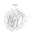
- FIG. 2 is a schematic perspective view which explains a first step of a method of production of a first radio frequency accelerator in the present embodiment.
- a plurality of component members are welded to form an acceleration cavity.
- the component member in the present embodiment has a shape obtained by splitting the tubular part 1.
- the direction which is shown by the arrow 90 is the direction which extends along the acceleration beam axis.
- a first component member 11 which has a first electrode 11a, a second component member 12 which has a second electrode 12a, a third component member 13 which has a third electrode 13a, and a fourth component member 14 which has a fourth electrode 14a are prepared in a preparation step.
- the plurality of component members 11 to 14 in the present embodiment are formed by cutting an aluminum block.
- the component members 11 to 14 in the present embodiment are comprised of the members forming the tubular part and the electrodes formed seamlessly.
- the surfaces of the component members 11 to 14 are polished.
- an aluminum block may be cut to form a component member comprised of the component member 11 and component member 12 joined together. Further, precision cutting may be performed so as not to polish the surfaces of the component members.
- the plurality of component members 11 to 14 are temporarily assembled into the shape of the tubular part 1 in a temporary assembly step.
- the first component member 11, second component member 12, third component member 13, and fourth component member 14 are mated together whereby butt lines 51 are formed.
- the tubular part 1 is split near the bottom part of the first electrode 11a. Further, the tubular part 1 is split near the bottom part of the second electrode 12a. In the present embodiment, the tubular part 1 is split so that the butt lines 51 become substantially parallel to the direction which extends along the acceleration beam axis.
- These component members are welded at the butt lines 51 by friction stir welding in the later welding step.
- the plurality of component members 11 to 14 in the present embodiment are formed with cutaway parts at the regions for friction stir welding in the later welding step. That is, the end parts to become the butt lines 51 are formed with cutaway parts.
- the first component member 11 is formed with a cutaway part 11b
- the second component member 12 is formed with a cutaway part 12b
- the third component member 13 is formed with a cutaway part 13b
- the fourth component members 14 is formed with a cutaway part 14b.
- These cutaway parts 11b, 12b, 13b, 14b are made to mutually face each other, whereby grooved parts 15 are formed. In this way, the regions for friction stir welding along the butt lines 51 are formed with grooved parts 15.
- the cutaway parts 11b, 12b, 13b, and 14b may be formed so that the mutually facing cutaway parts engage.
- the end faces of the tubular part 1 are formed with a plurality of threaded holes 41 for attaching end plates.
- These component members 11 to 14 are formed with through holes 42 for passing bolts which fasten the support members.
- support members are arranged inside the tubular part 1 for supporting the tubular part 1 from the inside.
- support members which contact the inside surface of the tubular part 1 are arranged in the spaces between the electrodes 11a, 12a, 13a, and 14a.
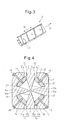
- FIG. 3 is a schematic perspective view of a support member which is used for the method of production of a first radio frequency accelerator of the present embodiment.
- the support member 21 in the present embodiment is formed so as to extend in the direction of the acceleration beam axis which is shown by the arrow 90 from near one end face of the tubular part 1 to near the other end face.
- the support member 21 is formed with threaded holes 43 into which bolts are inserted for fastening with a component member.
- the support member 21 is preferably formed by a material with a high stiffness.
- the support member 21 can be formed, for example, by stainless steel.
- a support member 21 is inserted into the space between the first electrode 11a and third electrode 13a. Further, similarly, corresponding support members are also inserted into the spaces between the other electrodes.
- the plurality of component members are mated to form the tubular part, then the support members are inserted, but the invention is not limited to this. It is also possible to arrange the support members at the inside when mating the component members. Through holes 42 which are formed at the component members 11 to 14 are formed so as to correspond to the threaded holes 43 which are formed at the support members 21.
- FIG. 4 is a schematic cross-sectional view which explains a second step of the method of production of the first radio frequency accelerator in the present embodiment.
- FIG. 4 is a schematic cross-sectional view of the time when placing support members in the spaces between the electrodes.
- the support members 21 in the present embodiment are arranged at positions away from the electrodes 11a, 12a, 13a, and 14a.
- the support members 21 are formed so as to be engaged with parts of the spaces between the electrodes 11a, 12a, 13a, and 14a.
- These support members 21 are formed so as to contact the butt lines 51 at the inside surface of the tubular part 1. That is, the support members 21 are formed so as to support the regions for friction stir welding from inside of the tubular part 1.
- the support members 21 After placing the support members 21 between the electrodes, the support members 21 are fastened by bolts 45 to the component members 11 to 14. By fastening the bolts 45, the support members 21 closely contact the inner surface of the tubular part 1. The support members 21 closely contact the inner surface of the region for friction stir welding.
- FIG. 5 is a schematic perspective view which explains a third step of the method of production of the first radio frequency accelerator in the present embodiment.
- temporary end plates 22 for production use are attached to the end faces of the both sides of the tubular part 1.
- the temporary end plates 22 are formed so as to be suitable for the shapes of the end faces of the tubular part 1.
- the temporary end plates 22 are formed with pluralities of holes.
- the temporary end plates 22 are fastened by bolts 46 to the tubular part 1.
- the temporarily assembled tubular part 1 is pressed from the outside.
- a not shown fastening device is used to fasten the tubular part 1.
- the tubular part 1 is pressed from the both sides in the direction of the acceleration beam axis so as to fasten it.
- the tubular part 1 is pressed from the both sides in the direction vertical to the acceleration beam axis for fastening.
- the support members 21 can maintain the component members 11 to 14 at predetermined positions against the pressing force.
- the inside surface of the tubular part is pressed by the support members while the outer surface of the tubular part is pressed by the fastening device. Since the tubular part is fastened from the inside surface and outside surface, it is possible to strongly maintain the shape of the tubular part. It is therefore possible to suppress changes in the dimensions at the next welding step. As a result, the acceleration cavity can be precisely formed.
- the plurality of component members are welded with each other by friction stir welding in a welding step.
- these component members 11 to 14 are welded along the butt lines 51.
- FIG. 6 is a schematic perspective view when performing friction stir welding in the present embodiment.
- FIG. 6 is an enlarged perspective view when welding the first component member 11 and the third component member 13.
- the welding device using friction stir welding includes a shoulder 61.
- the shoulder 61 as shown by the arrow 92, is formed so as to rotate.
- the welding device includes a pin 62 which sticks out from the shoulder 61.
- the pin 62 is formed so as to rotate together with the shoulder 61.
- the welding device as shown by the arrow 92, turns the shoulder 61 and pin 62 while pressing the pin 62 toward the members to be welded. Due to the heat of friction of the pin 62 and the members to be welded, the members to be welded are softened.
- the pin 62 is inserted inside of the members to be welded. By rotation of the pin 62, the area around the pin 62 is made to plastically flows. By making the pin 62 move along the welding line, one member is welded with the other member.
- the pin 62 is pressed on the butt line 51.
- the pin 62 is pressed from the outside of the tubular part 1.
- the first component member 11 and the third component member 13 soften.
- the pin 62 moves while maintaining a state where the tip part is buried in the softened part without passing through the first component member 11 and the third component member 13.
- the mutually welded component members soften from the surface at the side where the pin 62 is inserted up to the surface at the opposite side. That is, they are softened over the entire thickness direction.
- the friction stir welding is performed in the state with the tip part of the pin buried in the softened part, but the invention is not limited to this.
- the friction stir welding may also be performed in the state with the tip part of the pin passed slightly through the softened part. That is, if slight, the pin may also pass through. In this way, the friction stir welding may be performed in the state with the tip part of the pin substantially buried in the softened part.
- the tip part of the pin is arranged at the sunken part. Due to this method, it is possible to perform the friction stir welding while avoiding contact between the support member and the pin.
- the pin 62 By rotation of the pin 62, as shown by the arrow 93, by moving along the butt line 51, the first component member 11 and the third component member 13 are welded. A joint 52 comprised of the first component member 11 and the third component member 13 welded integrally is formed. By making the pin 62 move from one end part to the other end part of the butt line 51, the first component member 11 and the third component members 13 can be welded. The other component members can also be welded by similar friction stir welding.
- the temporary end plates 22 which are attached to the end faces of the tubular part 1 and the support members 21 which were arranged in the spaces between the electrodes 11a, 12a, 13a, and 14a are detached.
- the temporary end plates may be detached or the support members may be detached after the next reinforcing members finish being attached.
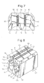
- FIG. 7 is a schematic perspective view of a tubular part after friction stir welding.
- a joint 52 is formed at substantially the entire butt line 51 of the first component member 11 and the third component member 13. Further, a joint 52 is formed at substantially the entire butt line 51 of the first component member 11 and the fourth component member 14.
- the butt line 51 between the second component member 12 and the third component member 13 and the butt line 51 between the second component member 12 and the fourth component member 14 can similarly be welded by friction stir welding. In this way, the component members 11 to 14 can be welded by friction stir welding.
- FIG. 8 is a schematic perspective view which explains a fifth step of the method of production of the first radio frequency accelerator in the present embodiment.
- FIG. 9 is a schematic cross-sectional view which explains a fifth step of the method of production of the first radio frequency accelerator in the present embodiment.
- FIG. 8 and FIG. 9 are schematic views when attaching reinforcing members to the grooved parts of the tubular part.
- reinforcing members 31 which correspond to the shapes of the grooved parts 15 are placed in the grooved parts 15.
- the reinforcing members 31 are formed to engage with the grooved parts 15.
- the grooved parts 15 in the present embodiment are formed to become square in cross-sectional shapes.
- block-shaped reinforcing members 31 are placed in the grooved parts 15.
- the cross-sectional shapes of the grooved parts which are employed may be any shapes so long as not obstructing movement of the shoulder of the welding device at the time of friction stir welding.
- the reinforcing members 31 are attached to the component members 11 to 14.
- friction stir welding is used to attach the reinforcing members 31. Friction stir welding is performed along the boundary lines of the component members 11 to 14 and the reinforcing members 31 to thereby form the joints 53.
- the reinforcing members 31 can be fastened to the component members 11 to 14.
- the method of fastening the reinforcing members is not limited to friction stir welding. Electron beam welding or any other method may also be used.
- the shapes of the reinforcing members may be formed so as to reinforce the parts where the thickness is made thinner due to forming cutaway parts of the component members. Alternatively, when the strength of the tubular part is maintained, the reinforcing members need not be arranged.
- the grooved parts may be used to form flow paths for a coolant. For example, it is possible to arrange reinforcing members at the top faces of the grooved parts to form paths for flowing cooling water of the acceleration cavity.
- the end plates may have exhaust pipes which are connected to the vacuum device or inlet pipes or outlet pipes of charged particles attached to them.
- This acceleration cavity may have a power supply device or vacuum device etc. connected to it for manufacture of the accelerator.
- the first radio frequency accelerator of the present invention is comprised of these component members welded by friction stir welding.
- the surface 52a at which the pin 62 of the welding device is inserted is formed with a stripe-shaped weld mark.
- the weld mark is, for example, formed so as to become a projecting shape at the opposite side to the direction of movement of the pin 62.
- the surface at the side where the pin 62 is inserted is formed with surface asperity.
- the surface 52b at the opposite side to the side where the pin 62 is inserted becomes smooth without the formation of stripe-shaped weld mark.
- the surface 52b is not formed with surface asperity.
- the surface roughness becomes smaller than the surface 52a.
- the accelerator in the present embodiment is formed with stripe-shaped weld mark at the outer surface of the tubular part 1, but is formed smooth at the inside surface of the tubular part 1.
- the magnitudes of the potentials of the electrodes at any time become equal.
- the polarities are the same at mutually facing electrodes.
- the polarities of the potentials of mutually facing electrodes in one direction are opposite to the polarities of the potentials of the mutual facing electrodes in a direction perpendicular to that one direction.
- the potentials of the first electrode 11a and the second electrode 12a are the maximum value (positive value with maximum magnitude)
- the potentials of the third electrode 13a and the fourth electrode 14a become the minimum value (negative value with maximum magnitude).
- the potentials of the electrodes become the reverse relationship.
- the surface roughness of the surfaces 52b of the joints 52 is small, so the power loss can be reduced. For example, even when not polishing the surface after friction stir welding, the power loss at the surfaces 52b of the joints 52 can be reduced. As a result, the quality factor of the accelerator can be raised.
- the surface is not polished after the welding step using friction stir welding, but the invention is not limited to this.
- the surface may also be polished after the welding step.
- friction stir welding is used to weld the component members, so the parts which rise in temperature are limited to ones near the joints. That is, the rise in temperature of the component members is limited to local parts. For this reason, for example, it is possible to avoid the component members from being heated overall such as when joining the members by brazing and possible to suppress heat deformation of the component members.
- Heat deformation includes deformation due to release of internal stress when releasing the fastening of the tubular part by the fastening device for a temporary assembly.
- it is possible to suppress deformation of the tubular part so it is possible to suppress deviation of the resonance frequency due to deformation. It is therefore possible to produce an accelerator precisely with respect to the design values.
- the radio frequency accelerator in the present embodiment is high in the quality factor, small in deviation of the resonance frequency, and otherwise excellent in electrical performance.
- the radio frequency accelerator in the present embodiment has a small surface roughness at the inner surfaces of the joints, so can be easily manufactured even without mechanical finishing after welding the plurality of component members. Alternatively, it is sufficient to perform simple grinding etc. and production is easy. For example, when using electron beam welding to weld the component members, the surface roughness at the penetration bead is large, so further grinding work or polishing work was necessary. In the radio frequency accelerator of the present embodiment, it is possible to produce an acceleration cavity with a small surface roughness of the inside surface even without performing such finishing work.
- the method of production of a radio frequency accelerator in the present embodiment it is possible to confirm the state of welding in the middle of the welding step. For example, it is possible to find out problems in the middle of the welding step and correct the work etc. As a result, the yield can be improved.
- a support member for supporting the tubular part from the inside is placed inside the temporarily assembled tubular part.
- the plurality of component members in the present embodiment have shapes obtained by splitting the tubular part near the bottom parts of the electrodes.
- Support members which are formed so as to contact the butt lines of the plurality of component members are employed. Due to this method, it is possible to more reliably suppress deformation of the tubular part in friction stir welding.
- the support members are preferably fastened to the component members. Due to this method, it is possible to more reliably suppress deformation of the tubular part.
- the support members in the present embodiment can support the joints against the pressing force of the welding device at the time of friction stir welding. Further, after performing the friction stir welding, the support members may be detached without damaging the inside surface of the tubular part.
- the support members in the present embodiment are formed in cylindrical shapes which extend in the direction of the acceleration beam axis, but the invention is not limited to this. The support members may be formed so as to enable the tubular part to be supported from the inside.
- bolts are passed through the through holes which are formed in the component members so as to fasten the support members, but the method of fastening the support members is not limited to this. Any method may be used to fasten the support members to the component members.
- the through holes are preferably small in diameter so that the effect on the resonance frequency of the acceleration cavity becomes small.
- the through holes which are formed in the component members may be utilized for other applications as well.
- the through holes which are formed in the component members may be used as connection ports for connecting a vacuum device.
- the component members in the present embodiment are formed with cutaway parts at the regions for performing friction stir welding. After the welding step using friction stir welding, reinforcing members which have shapes which engage with the cutaway parts are attached. Due to this method, it is possible to reduce the thickness of the regions for performing friction stir welding and easily perform friction stir welding. Alternatively, the friction stir welding can be performed in a short time. Furthermore, by fastening the reinforcing members to the component members, deformation of the tubular part can be suppressed during the manufacturing period or the period of operation of the accelerator.
- component members comprised of the members forming the tubular part and electrodes seamlessly formed are prepared. That is, component members comprised of parts for forming the tubular parts and electrodes made from the same materials are employed. Due to this method, the positional relationship between the tubular part and the electrodes can be maintained precisely at the time of machining. For this reason, the dimensional precision becomes higher and it is possible to provide a radio frequency quadrupole accelerator better in electrical performance.
- the radio frequency quadrupole accelerator is not limited to an accelerator which contains four vanes.
- the present invention may also be applied to a four-rod type of radio frequency quadrupole accelerator in which four electrodes are formed into rod shapes and the rod-shaped electrodes are arranged substantially in parallel in the direction of the acceleration beam axis.
- electrodes are arranged at all of the component members, but the invention is not limited to this. It is sufficient that at least one of the plurality of component members include an electrode.
- FIG. 10 is a schematic perspective view which explains a method of production of a second radio frequency accelerator in the present embodiment.
- FIG. 10 is a schematic perspective view of a tubular part of a second radio frequency accelerator in this embodiment.
- the second radio frequency accelerator is a drift tube accelerator.
- a tube-shaped first electrode 11a and a tube-shaped second electrode 12a are arranged along the acceleration beam axis of the charged particles.
- the charged particles pass through the insides of these electrodes 11a and 12a.
- the first electrode 11a is formed at a first component member 11.
- the second electrode 12a is formed at a second component member 12.
- the electrodes may also be formed at just one of the first component member 11 or second component member 12.
- the electrode parts may be formed to be detachable.
- the third component member 13 and fourth component member 14 at the second radio frequency accelerator do not have electrodes.
- the third component members 13 and the fourth component members 14 form the tubular part 1 of the acceleration cavity.
- the tubular part 1 includes a plurality of component members 11 to 14. These component members are mated at the butt lines 51.
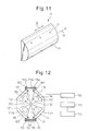
- FIG. 11 is a schematic perspective view of a support member used for the method of production of the second radio frequency accelerator in the present embodiment.
- the support member 21 is formed so as to contact the inside surface of the third component member 13 or fourth component member 14.
- the support member 21 is formed with threaded holes 43 through which bolts are inserted for fastening the support member 21.
- the support member 21 may have a cross-sectional shape other than a semi-circular shape so long as being a shape which suitably contacts the inner surface of the component members.
- a support member 21 is inserted to the inside of the tubular part 1.
- the support member 21 is formed so as to closely contact a butt line 51 from the inside surface of the tubular part 1.
- component members which have shapes obtained by splitting the tubular part near the bottom parts of the electrodes are employed, but the invention is not limited to this. It is possible to employ component members which have shapes obtained by splitting the tubular part at any positions. For example, referring to FIG. 9 , it is also possible to employ component members which have shapes obtained by splitting the tubular part 1 at substantially intermediate points between mutually adjoining electrodes in the case where the cross-sectional shape of the outer surface of the tubular part 1 is formed to be substantially circular.
- friction stir welding is performed in a direction substantially parallel to the acceleration beam axis, but the invention is not limited to this. It is possible to perform the friction stir welding in any direction.
- the component members in the present embodiment are formed by aluminum, but the invention is not limited to this.
- the material of the component members used may be any material for which friction stir welding can be performed.
- copper may be used.
- a radio frequency quadrupole accelerator and a drift tube accelerator were taken up as examples for the explanation, but the invention is not limited to this. It is possible to apply the present invention to any radio frequency accelerator.
- the invention is not limited to a linear accelerator.
- the present invention may also be applied to an acceleration cavity for a circular accelerator.
- FIG. 12 is a schematic view of the radio frequency quadrupole accelerator in the present embodiment.
- the radio frequency quadrupole accelerator is provided with an acceleration cavity 101.
- the acceleration cavity 101 includes a tubular part 102 which is formed into a tubular shape.
- the acceleration cavity 101 includes electrodes 121 to 124 called “vanes" which stick out from the tubular part 102 toward the inside. These electrodes 121 to 124 are electrically connected to the tubular part 102.
- the radio frequency quadrupole accelerator in the present embodiment is provided with a first electrode 121, second electrode 122, third electrode 123, and fourth electrode 124.
- the four electrodes 121 to 124 in the present embodiment are seamlessly formed with the members which form the tubular part 102. These electrodes 121 to 124 are formed so as to extend along the acceleration beam axis of the charged particles.
- the electrodes 121 to 124 in the present embodiment are formed into triangular prism shapes. These electrodes 121 to 124 are formed so that the vertexes of the triangular shapes of the cross-sectional shapes face the acceleration beam axis of the charged particles.
- the tip parts of the electrodes 121 to 124 facing the acceleration beam axis are formed in wave shapes called "modulation" so as to form an electrical field which accelerates and focuses charged particles in the direction of the acceleration beam axis.
- the shapes of the electrodes are not limited to this. It is possible to employ any shapes which stick out from the tubular part and whereby the tips of the electrodes approach the acceleration beam axis.
- the electrodes may also be formed in plate shapes.
- the radio frequency quadrupole accelerator in the present embodiment is provided with a power supply device for supplying radio frequency power.
- the power supply device includes a radio frequency signal generator 172.
- the radio frequency signal generator 172 is connected to a preamplifier 173 and a main amplifier 174.
- the radio frequency power which is generated by the radio frequency signal generator 172 is amplified by the preamplifier 173 and main amplifier 174.
- the radio frequency power which is output from the main amplifier 174 is supplied through a coupler 175 to the acceleration cavity 101.
- the power supply device is not limited to this. It is possible to employ any device which can supply the acceleration cavity 101 with radio frequency power.
- the acceleration cavity 101 has a floating capacitance and floating inductance dependent on the shapes of the tubular part 102 and their electrodes 121 to 124. These floating capacitance and floating inductance form part of an electrical circuit.
- an accelerating electric field is excited.
- the potentials of the first electrode 121, second electrode 122, third electrode 123, and fourth electrode 124 become the same.
- the electrode pair of the mutually facing first electrode 121 and second electrode 122 and the electrode pair of the mutually facing third electrode 123 and fourth electrode 124 become opposite polarities (plus or minus).
- the acceleration beam axis is arranged in the space between the four electrodes 121 to 124. The charged particles move while being accelerated along the acceleration beam axis.
- FIG. 13 is a schematic perspective view of an acceleration cavity in the present embodiment.
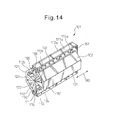
- FIG. 14 is a schematic perspective view when cutting the acceleration cavity in the present embodiment.
- FIG. 14 is a perspective view of the time when cutting the acceleration cavity along the line A-A in FIG. 13 .
- the arrow mark 190 indicates the direction of extension of the acceleration beam axis of the charged particles.
- the acceleration cavity 101 in the present embodiment is formed so as to extend in parallel with the direction of the acceleration beam axis.
- the acceleration cavity 101 in the present embodiment is provided with three component members.
- the acceleration cavity 101 is provided with a center member 111 which includes a first electrode 121 and a second electrode 122.
- the acceleration cavity 101 is provided with a first side member 112 which includes a third electrode 123.
- the acceleration cavity 101 is provided with a second side member 113 which includes a fourth electrode 124.
- the first side member 112 is arranged at one side of the center member 111.
- the second side member 113 is arranged at the other side of the center member 111.
- the center member 111, first side member 112, and second side member 113 in the present embodiment are respectively seamlessly formed from single members. That is, the center member and side members are formed from single materials without partitioning lines, weld lines, etc. of a plurality of parts. Note that, a vacuum port or other additional members may also be arranged in advance at the center member or side member.
- the center member 111, first side member 112, and second side member 113 are fastened together by fastening members.
- fastening members bolts 151 and nuts 152 are used for fastening.
- O-rings 155 are arranged as vacuum sealing members. By these vacuum sealing members being arranged between the component members, the acceleration cavity 101 is sealed.
- FIG. 15 is a schematic perspective view of the center member in the present embodiment.
- the center member 111 has a center outer frame part 111a which forms the center part of the outer frame part of the acceleration cavity 101.
- the center outer frame part 111a is formed in a window shape when viewed by a plan view.
- the center member 111 has a first electrode 121 which sticks out from the center outer frame part 111a toward the inside.
- the center member 111 includes a second electrode 122 which sticks out from the center outer frame part 111a toward the inside.
- the first electrode 121 and the second electrode 122 are arranged so that the tips face the acceleration beam axis.
- the end face in the direction of the acceleration beam axis is formed with a beam injection port 161 into which the charged particles enter. Further, the end face at the opposite side to the end face where the beam injection port 161 is formed is formed with a beam extraction port 162 from which the charged particles are extracted.
- the beam injection port 161 and the beam extraction port 162 are formed on an extension of the acceleration beam axis.
- the center outer frame part 111a is formed with through holes 114 for passing bolts. Pluralities of through holes 114 are formed along the shape of the center outer frame part 111a.
- the contact surface which contacts the first side member 112 or second side member 113 is formed with a grooved part 116 for placement of an O-ring 155.
- the grooved part 116 is formed in a closed shape when viewed by a plan view.
- a grooved part for placement of an O-ring or other vacuum sealing member may also be arranged at the first side member 112 and second side member 113.
- the center member 111 in the present embodiment is formed with reference marks 131 for determining the positions of the members with each other in the assembly step of assembling the members.
- the end face where the beam injection port 161 is formed is formed with a reference mark 131.
- the end face where the beam extraction port 162 is formed is formed with a reference mark 131.
- the reference marks 131 in the present embodiment are formed in straight shapes.
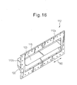
- FIG. 16 is a schematic perspective view of a side member in the present embodiment.
- the first side member 112 has a first side outer frame part 112a which forms a side part of the outer frame part of the acceleration cavity 101.
- the first side outer frame part 112a is formed into a window shape when viewed by a plan view.
- the first side member 112 has a first wall part 112b which has the shape of part of the acceleration cavity.
- the first wall part 112b forms the tubular part 102 of the acceleration cavity 101.
- the first wall part 112b is formed so that the first side outer frame part 112a extends toward the outside.
- the first wall part 112b is formed into a plate shape and is joined with the first side outer frame part 112a.
- the first side member 112 includes a third electrode 123 which sticks out from the first wall part 112b toward the inside.
- the first side outer frame part 112a is formed with through holes 115 for passing bolts.
- the first side outer frame part 112a is formed with positioning marks 132 for determining the assembly position in the assembly step.
- the positioning marks 132 are formed at the end faces at the both sides in the direction of the acceleration beam axis.
- the first side member 112 among the two side members is taken up as an example for the explanation, but the second side member 113 has a similar configuration to the first side member 112.
- the second side member 113 includes a window-shaped second side outer frame part 113a.
- the second side member 113 includes a second wall part 113b which extends from the second side outer frame part 113a toward the outside and has the shape of part of the acceleration cavity.
- the second side member 113 includes a fourth electrode 124 which sticks out from the second wall part 113b toward the inside.
- the acceleration cavity 101 is formed by the center outer frame part 111a and the first side outer frame part 112a in close contact with each other. Further, the center outer frame part 111a and the second side outer frame part 113a are in close contact. The center outer frame part 111a and the side outer frame parts 112a and 113a are fastened with each other by bolts 151 and nuts 152. Due to the center outer frame part 111a and side outer frame parts 112a and 113a, the outer frame part of the acceleration cavity 101 are formed.
- the center member 111, first side member 112, and second side member 113 in the present embodiment are formed. These component members are prepared in a member preparation step.
- the member preparation step in present embodiment includes a step of forming the center member 111, first side member 112, and second side member 113 seamlessly from single members.
- an aluminum block is mechanically machined so as to form the component members.
- the step of forming the component members it is preferable to machine them out by a high precision.
- a 3D measuring device etc. is preferably used to confirm the dimensions of the center member and the side members.
- the surface roughness is preferably made small.
- the inside surface of the tubular part and the surfaces of the electrodes are preferably worked to a high precision processing or ground etc. so as to reduce the surface roughness.
- the center outer frame part 111a of the center member 111 is formed with the reference marks 131. Further, the first side outer frame part 112a of the first side member 112 is formed with positioning marks 132. The second side outer frame part 113a of the second side member 113 is formed with positioning marks 132. At the grooved part 116 which is formed at the center member 111, an O-ring 155 is placed as a vacuum sealing member.
- the center member 111, first side member 112, and second side member 113 are fastened together by bolts and nuts in the assembly step.
- the first side member 112 and the second side member 113 are placed at the both sides of the center member 111.
- the reference marks 131 which are formed at the center outer frame part 111a and the positioning marks 132 which are formed at the side outer frame parts 112a and 113a are aligned by positioning.
- the bolts are fastened to join the center outer frame part 111a with the first side outer frame part 112a and second side outer frame part 113a.
- the center member 111, the first side member 112 and the second side member 113 are thereby fastened to each other.
- bolts etc. as the fastening members, it is preferable to tighten them while controlling the torque.
- This method enables the contact surfaces of the component members to be brought into contact with uniform pressure.
- the acceleration cavity can be formed in this way. By connecting a power supply device, vacuum device, etc. to this acceleration cavity, an accelerator can be produced.
- the reference marks and positioning marks used for aligning are not limited to straight line shapes. Marks of any shapes can be employed. Further, the reference marks and positioning marks in the present embodiment are formed at the end faces in the direction of the acceleration beam axis among the outer surfaces of the acceleration cavity, but the invention is not limited to this. Reference marks and positioning marks may be formed at any positions of the outer surfaces of the acceleration cavity. For example, at the outer surfaces of the outer frame part of the acceleration cavity, the end faces in the direction vertical to the acceleration beam axis may be formed with the reference marks and positioning marks.
- the magnitudes of the potential of the electrodes at any time are equal.
- the polarities are the same at mutually facing electrodes.
- the polarities of the potentials of mutually facing electrode in one direction are opposite to the polarities of the potentials of the mutual facing electrodes in a direction perpendicular to that one direction.
- the potentials of the first electrode 121 and the second electrode 122 are the maximum value (positive value with maximum magnitude)
- the potentials of the third electrode 123 and the fourth electrode 124 become the minimum value (negative value with maximum magnitude).
- the potentials of the electrodes become the reverse relationship.
- Radio frequency current flows through inside surface of the tubular part of the acceleration cavity 101 due to the skin effect. For this reason, the current, as shown by the arrow 194, flows along the surfaces of the electrodes 121 to 124 and the inner surface of the tubular part 102.
- the surfaces of the electrodes 121 to 124 and the inner surface of the tubular part 102 in the present embodiment are free of weld marks and other surface asperity, so the power loss can be reduced. As a result, the quality factor of the accelerator can be raised.
- the center member and the two side members are formed in advance and these component members are fastened with each other by fastening members.
- the assembly step it is possible to avoid a rise in temperature of the component members.
- the assembly step it is possible to avoid the component members from being heated overall in the case of using brazing for joining them and possible to suppress heat deformation of the component members.
- Heat deformation includes deformation due to internal stress being released when releasing the fastening of the tubular part by the fastening devices for a temporary assembly.
- the radio frequency quadrupole accelerator in the present embodiment is high in quality factor, small in deviation of the resonance frequency, and otherwise excellent in electrical performance.
- the radio frequency quadrupole accelerator in the present embodiment does not have joints of component parts joined by welding etc., so it is not necessary to perform the mechanical finishing work after welding a plurality of component members and therefore possible to easily manufacture the accelerator. For example, when using electron beam welding to weld component members, the surface roughness was large, so further grinding work and polishing work were necessary.
- the radio frequency quadrupole accelerator of the present embodiment enables manufacture of an acceleration cavity with a small surface roughness at the inside surface even without such finishing work.
- the radio frequency quadrupole accelerator in the present embodiment enables confirmation of the state of assembly in the middle of the assembly step. For example, by using a predetermined measuring device, it is possible to find out problems in the middle of the assembly step and correct the work etc. As a result, it is possible to improve the yield. Furthermore, it is possible to easily disassemble the accelerator after assembly in accordance with need by detaching the fastening members. For example, it is possible to readjust the positioning. Alternatively, it is possible to easily change the vacuum sealing members when replacing them.
- the member preparation step includes a step of forming the reference marks 131 at the end faces of the center member 111 and positioning marks 132 at the end faces of the first side member 112 and the end faces of the second side member 113.
- the assembly step includes a step for positioning by alignment of the reference marks 131 and the positioning marks 132.
- the method of positioning in the assembly step is not limited to this. Any method may be employed.
- a laser tracker can be used for positioning.
- the outer surfaces which extend in the direction parallel to the acceleration beam axis are formed with a high precision. These outer surfaces can be used as reference surfaces where the reflectors are placed.
- the center member is formed with a first engagement part and the first side member and second side member are formed with second engagement parts.
- the first engagement part and the second engagement parts are made to engage with each other, whereby the members can be positioned with each other. This method enables easy positioning.
- the center member and the side members are made able to be positioned by forming projecting parts as first engagement parts at the center member and forming grooved parts as second engagement parts at the side members.
- the projecting parts and grooved parts may be made to engage to easily position the center member and side members.
- the center member is formed with first positioning holes, while the first side member and second side member are formed with second positioning holes.
- the assembly step by inserting positioning pins into the first positioning holes and second positioning holes, the members can be positioned with each other. This method enables easy positioned.
- the center member and side members are formed with positioning holes between the through holes for the bolts used as the fastening members.
- the positioning holes are formed so that when assembled into the acceleration cavity, the positioning holes of the center member and the positioning holes of the side members are communicated with each other.
- the positioning holes are preferably formed at a plurality of locations.
- pins which can closely fit into the positioning holes are inserted into the positioning holes of the center member and the positioning holes of the side members, whereby the center member and side members can be easily positioned.
- bolts which pass through the center member, first side member, and second side member are used to fasten these component members, but the invention is not limited to this.
- Any fastening members can be used to fasten the center member and the side members.
- the center member may be formed with threaded through holes or blind holes. By inserting bolts from the outsides of the through holes of the first side member, the first side member can be fastened to the center member. Further, by inserting bolts from the outsides of the through holes of the second side member, the second side member can be fastened to the center member. In this way, the side members may be individually fastened to the center member. Due to this method, it is possible to position the members with each other and fasten the members with each other more easily.
- the center member and side members are formed seamlessly to enable easy manufacture of an accelerator which is long in the direction of the acceleration beam axis.
- the member forming the tubular part of the acceleration cavity and the electrodes are formed seamlessly.
- it may be considered to manufacture the tubular part and the electrodes separately, then use bolts etc. to fasten the electrodes to the tubular part.
- the number of parts become greater and positioning of the component members with each other becomes difficult.
- the positional relationship of the tubular part and the electrodes is high in dimensional precision since the precision at the time of machining is maintained.
- a radio frequency quadrupole accelerator which is excellent in electrical performance can be provided.
- the radio frequency quadrupole accelerator in the present embodiment can interpose conductive members in the region where the center member 111 and the first side member 112 contact and in the region where the center member 111 and the second side member 113 contact.
- conductive members instead of rubber O-rings used as vacuum sealing members, metal sealing members may be placed.
- metal sealing members may be placed.
- the conduction between the center member 111 and the side members 112 and 113 can be improved.
- the desired electrical performance can be secured.
- a radio frequency quadrupole accelerator rises in temperature due to electrical resistance due to operation. If the temperature greatly rises, the O-rings are liable to damage. In such a case, it is possible to employ metal sealing members so as to avoid damage of the sealing members.
- metal vacuum sealing members are suitable for a radio frequency quadrupole accelerator which is continuously operated.
- a radio frequency accelerator may be provided with a cooling device for cooling the acceleration cavity.
- cooling tubes for flowing cooling water may be arranged at the insides of the electrodes or at the surfaces of the side members.
- the radio frequency quadrupole accelerator in the present embodiment is formed so that the cross-sectional shape of the tubular part becomes a regular octagon, but the invention is not limited to this. It is possible to employ any shape by which suitable electrical performance as a radio frequency quadrupole accelerator can be realized.
- the tubular part can be formed to become a circular or another polygonal cross-sectional shape.
- the center member and side members are formed from aluminum, but the invention is not limited to this.
- the center member and side members may be formed from any material.
- the component members may be formed from a block of copper.
Landscapes
- Physics & Mathematics (AREA)
- Engineering & Computer Science (AREA)
- Plasma & Fusion (AREA)
- Spectroscopy & Molecular Physics (AREA)
- Particle Accelerators (AREA)
Abstract
Description
- The present invention relates to a radio frequency accelerator, a method of production of a radio frequency accelerator, a radio frequency quadrupole accelerator, and a method of production of a radio frequency quadrupole accelerator.
- Known in the art is a radio frequency accelerator for accelerating ions, electrons, or other charged particles. A radio frequency accelerator is provided inside it with an acceleration cavity for accelerating charged particles. The acceleration cavity forms a resonance circuit and has a unique resonance frequency. By supplying radio frequency power in accordance with this resonance frequency from the outside, a radio frequency electric field is excited inside of the acceleration cavity. A radio frequency accelerator can accelerate charged particles up to a desired energy by injecting charged particles at a predetermined timing in the state where the radio frequency electric field is excited.
- Radio frequency accelerators are classified by the shape of the path of the charged particles into linear accelerators (linacs) and circular accelerators. Linear accelerator is accelerator with straight paths of the charged particle beam, while circular accelerators are accelerators with curved paths of the charged particle beam. Linear accelerators include, for example, radio frequency quadrupole accelerators, drift tube accelerators, etc.
- A radio frequency quadrupole accelerator is provided with four electrodes. The four electrodes form two mutually facing pairs. At the tips of the electrodes, wave shapes suitable for acceleration of a beam are formed in the direction of the acceleration beam axis. In the space surrounded by the four electrodes, an electric field is formed for accelerating and focusing a beam. By injecting charged particles into this space, the charged particles are accelerated.
- Japanese Patent Publication (A) No.
5-62798 -
- PLT 1: Japanese Patent Publication (A) No.
5-62798 - The indicators which show the electrical performance of an accelerator include the "quality factor". For example, the indicators which shown the electrical performance of a radio frequency quadrupole accelerator also include the quality factor. The quality factor is proportional to the value of the energy which is stored inside of the cavity at the time of operation of the accelerator divided by the power loss. The larger the quality factor, the longer the operating time per unit energy and the better the operating efficiency.
- When a radio frequency power is supplied to a radio frequency accelerator from the outside of the acceleration cavity, an accelerating electric field is excited inside of the acceleration cavity and radio frequency current flows through the inside surface of the acceleration cavity. The acceleration cavity has an electrical resistance based on the shape, material, etc. Power is consumed in accordance with the magnitude of this electrical resistance. If the electrical resistance is large, the power consumption becomes larger and the quality factor becomes lower. The electrical resistance changes due to the surface roughness at the inside surface of the acceleration cavity as well and, as a result, the quality factor changes. The smaller the surface roughness of the inside surface of acceleration cavity, the higher the quality factor.
- In the method of production of a radio frequency accelerator of the prior art, a plurality of component members are formed in advance and then the plurality of component members are joined together to form an acceleration cavity. In the step of forming the plurality of component members, it is possible to manufacture component members which are high in dimensional precision and further are small in surface roughness. For example, by cutting with a high precision, it is possible to manufacture component members with a high dimensional precision. Further, it is possible to grind or polish the surfaces of the component members in various ways so as to reduce the surface roughness.
- On the other hand, in the step of assembling the acceleration cavity, brazing or electron beam welding etc. were used to join the plurality of component members. As a result, depending on the work method, the surface conditions of the joints deteriorated and the quality factor of the accelerator became smaller. To raise the quality factor, it was necessary to perform grinding work or polishing work after assembling the acceleration cavity.
- Further, as explained above, an acceleration cavity has a unique resonance frequency. The resonance frequency depends on the shape of the acceleration cavity. The resonance frequency greatly depends on the shape in the extent that the resonance frequency is affected by the heat expansion or heat contraction in micron units due to temperature changes of the acceleration cavity. For this reason, the resonance frequency greatly depends on the precision of fabrication. In the manufacture of an accelerator cavity, preferably the cavity is produced with dimensions matching the design values.
- In this regard, in a method of production of a conventional radio frequency accelerator, there was sometimes the problem that dimensional changes occurred in the step of joining the component members. For example, when joining component members together by brazing, the component members were temporarily assembled, then brazing filler metals were placed at the joining parts. Next, the temporarily assembled component members were placed inside a high temperature furnace to make the brazing filler metals melt. At this time, the component members were heated overall and sometimes dimensional changes occurred due to the temperature changes. That is, the component members rose in temperature overall, so heat deformation occurred. As a result, sometimes the resonance frequency ended up greatly deviating from the design value.
- In this way, in a conventional radio frequency accelerator and method of production of a radio frequency accelerator, the electrical performance tended to end up deteriorating from the design values. Special work was required for improving the electrical performance. Further, individual differences arose in the electrical performance, so even with the same type of accelerator, processing was necessary while considering the individual differences.
- The present invention provides a radio frequency accelerator and a radio frequency quadrupole accelerator which are excellent in electrical performance and easy to manufacture and a method of production of the radio frequency accelerator and method of production of the radio frequency quadrupole accelerator.
- A method of production of a radio frequency accelerator of the present invention provides a method of production of a radio frequency accelerator which has a tubular part which forms an acceleration cavity and which has electrodes arranged inside of the tubular part, including a preparation step of preparing a plurality of component members which have shapes obtained by splitting the tubular part, a temporary assembly step of making the plurality of component members mate with each other to temporarily assemble them into the shape of the tubular part, a step of fastening a temporarily assembled tubular part by pressing it from the outer side, and a welding step of welding the plurality of component members together. The temporary assembly step includes a step of placing, inside of the tubular part, support members for contacting the inside surface of the tubular part and supporting the tubular part from the inside, and the welding step includes a step of welding the plurality of component members along the butt lines by friction stir welding.
- In the present invention, preferably the plurality of component members are formed with cutaway parts at the regions for friction stir welding, and the method includes a step of attaching reinforcing members which have shapes which engage with the cutaway parts after the welding step.
- In the present invention, the method may be a method of production of an accelerator which is provided with four electrodes which stick out from the tubular part toward the acceleration beam axis of the charged particles, where the plurality of component members have shapes obtained by splitting the tubular part near the bottom parts of the electrodes and where the temporary assembly step includes a step of arranging support members which contact butt lines of the plurality of component members and extend along the acceleration beam axis.
- In the present invention, preferably the preparation step prepares component members comprised of members which form the tubular part and electrodes which are formed seamlessly.
- The radio frequency accelerator of the present invention is provided with a tubular part which forms an acceleration cavity and which includes a plurality of component members, at least one component member among the plurality of component members includes an electrode, the plurality of component members are welded with each other through joints which are formed by friction stir welding, the joints are formed with stripe-shaped weld marks at outer surfaces, and a surface roughness of the inner surfaces is smaller than a surface roughness at the outer surfaces.
- In the present invention, preferably the tubular part has cutaway parts which are formed at regions of the joints of the friction stir welding and the radio frequency accelerator is further provided with reinforcing members which are engaged with the cutaway parts to be fastened to the component members.
- The radio frequency quadrupole accelerator of the present invention is provided with a center member which includes a center outer frame part, a first electrode which sticks out from the center outer frame part toward the inside, and a second electrode which sticks out from the center outer frame part toward the inside, a first side member which includes a first side outer frame part, a first wall part which extends from the first side outer frame part toward the outside and which has the shape of part of an acceleration cavity, and a third electrode which sticks out from the first wall part toward the inside and which is arranged at one side of the center member, and a second side member which includes a second side outer frame part, a second wall part which extends from the second side outer frame part toward the outside and which has the shape of part of an acceleration cavity, and a fourth electrode which sticks out from the second wall part toward the inside and which is arranged at the other side of the center member. The center member, the first side member, and the second side member are respectively formed seamlessly from single members. The center member, the first side member, and the second side member are configured so that the center outer frame part, the first side outer frame part, and the second side outer frame part are fastened by fastening members.
- In the present invention, preferably the center member, the first side member, and the second side member are fastened with each other through conductive members.
- A method of production of a radio frequency quadrupole accelerator of the present invention includes a member preparation step which prepares a center member which includes a center outer frame part, a first electrode which sticks out from the center outer frame part and a second electrode which sticks out from the center outer frame part, a first side member which includes a first side outer frame part, a first wall part which has the shape of part of an acceleration cavity, and a third electrode which sticks out from the first wall part, and a second side member which includes a second side outer frame part, a second wall part which has the shape of part of an acceleration cavity, and a fourth electrode which sticks out from the second wall part, and an assembly step of arranging the first side member and the second side member at the both sides of the center member and fastening the center outer frame part, first side outer frame part, and second side outer frame part with each other by fastening members. The member preparation step includes a step of respectively forming the center member, first side member, and second side member seamlessly from single members.
- In the present invention, preferably the member preparation step includes a step of forming reference marks at an outer surface of the center member and a step of forming positioning marks at the outer surface of the first side member and the outer surface of the second side member, and the assembly step includes a step of aligning the reference marks and the positioning marks to position the members with each other.
- In the present invention, preferably the member preparation step includes a step of forming first engagement parts at the center member and a step of forming second engagement parts at the first side member and second side member, and the assembly step includes a step of making the first engagement parts and the second engagement parts engage with each other so as to position the members with each other.
- In the present invention, preferably the member preparation step includes a step of forming first positioning holes at the center member and a step of forming second positioning holes at the first side member and the second side member, and the assembly step includes a step of inserting positioning pins in the first positioning holes and the second positioning holes so as to position the members with each other.
- According to the present invention, it is possible to provide a radio frequency accelerator and a radio frequency quadrupole accelerator which are excellent in electrical performance and easy to manufacture and a method of production of the radio frequency accelerator and a method of production of the radio frequency quadrupole accelerator.
-
-
FIG. 1 is a schematic view of a first radio frequency accelerator inEmbodiment 1. -
FIG. 2 is a schematic perspective view which explains a first step of a method of production of the first radio frequency accelerator inEmbodiment 1. -
FIG. 3 is a schematic perspective view of a support member which is used for the method of production of the first radio frequency accelerator inEmbodiment 1. -
FIG. 4 is a schematic cross-sectional view which explains a second step of the method of production of the first radio frequency accelerator inEmbodiment 1. -
FIG. 5 is a schematic perspective view which explains a third step of the method of production of the first radio frequency accelerator inEmbodiment 1. -
FIG. 6 is a schematic perspective view which explains friction stir welding inEmbodiment 1. -
FIG. 7 is a schematic perspective view which explains a fourth step of the method of production of the first radio frequency accelerator inEmbodiment 1. -
FIG. 8 is a schematic perspective view which explains a fifth step of the method of production of the first radio frequency accelerator inEmbodiment 1. -
FIG. 9 is a schematic cross-sectional view which explains a fifth step of the method of production of the first radio frequency accelerator inEmbodiment 1. -
FIG. 10 is a schematic perspective view which explains a method of production of a second radio frequency accelerator ofEmbodiment 1. -
FIG. 11 is a schematic perspective view of a support member which is used for the method of production of the second radio frequency accelerator ofEmbodiment 1. -
FIG. 12 is a schematic view of a radio frequency quadrupole accelerator in Embodiment 2. -
FIG. 13 is a schematic perspective view of an acceleration cavity of a radio frequency quadrupole accelerator in Embodiment 2. -
FIG. 14 is a schematic perspective view showing cut away the acceleration cavity of the radio frequency quadrupole accelerator in Embodiment 2. -
FIG. 15 is a schematic perspective view of a center member in Embodiment 2. -
FIG. 16 is a schematic perspective view of a first side member in Embodiment 2. - Referring to
FIG. 1 to FIG. 11 , a radio frequency accelerator and a method of production of a radio frequency accelerator inEmbodiment 1 will be explained. In the present embodiment, a linear accelerator is taken up as an example for explanation. -
FIG. 1 is a schematic view of a first radio frequency accelerator in the present embodiment. The first radio frequency accelerator is a quadrupole type (RFQ) accelerator. The radio frequency accelerator is provided with atubular part 1 which forms an acceleration cavity and is formed in a tubular shape. Inside of thetubular part 1, electrodes called "vanes" are arranged. These electrodes are electrically connected to thetubular part 1. - The first radio frequency accelerator is provided with a
first electrode 11a,second electrode 12a,third electrode 13a, andfourth electrode 14a. The fourelectrodes tubular part 1. Theseelectrodes electrodes electrodes electrodes electrodes tubular part 1. Cutaway parts may also be formed near the bottom parts of the both ends of these electrodes. - The radio frequency accelerator in the present embodiment is provided with a power supply device for supplying radio frequency power. The power supply device includes a radio
frequency signal generator 72. The radiofrequency signal generator 72 is connected to apreamplifier 73 and amain amplifier 74. The radio frequency power which is oscillated by the radiofrequency signal generator 72 is amplified by thepreamplifier 73 andmain amplifier 74. The radio frequency power which is output from themain amplifier 74 is supplied through acoupler 75 to the acceleration cavity. The power supply device is not limited to this. It is possible to employ any device which can supply the acceleration cavity with radio frequency power. - The acceleration cavity has a floating capacitance and floating inductance which depend on the shapes of the
tubular part 1 and theelectrodes first electrode 11a,second electrode 12a,third electrode 13a, andfourth electrode 14a become the same. Further, the electrode pair of the mutually facingfirst electrode 11a andsecond electrode 12a and the electrode pair of the mutually facingthird electrode 13a andfourth electrode 14a have opposite polarities (plus or minus). The acceleration beam axis is arranged in the space surrounded by the four electrodes. The charged particles move while being accelerated along the acceleration beam axis. -
FIG. 2 is a schematic perspective view which explains a first step of a method of production of a first radio frequency accelerator in the present embodiment. In the method of production of a radio frequency accelerator in the present embodiment, a plurality of component members are welded to form an acceleration cavity. The component member in the present embodiment has a shape obtained by splitting thetubular part 1. The direction which is shown by thearrow 90 is the direction which extends along the acceleration beam axis. - In the present embodiment, a
first component member 11 which has afirst electrode 11a, asecond component member 12 which has asecond electrode 12a, athird component member 13 which has athird electrode 13a, and afourth component member 14 which has afourth electrode 14a are prepared in a preparation step. The plurality ofcomponent members 11 to 14 in the present embodiment are formed by cutting an aluminum block. Thecomponent members 11 to 14 in the present embodiment are comprised of the members forming the tubular part and the electrodes formed seamlessly. Furthermore, in the present embodiment, the surfaces of thecomponent members 11 to 14 are polished. In the manufacture of thecomponent members 11 to 14, an aluminum block may be cut to form a component member comprised of thecomponent member 11 andcomponent member 12 joined together. Further, precision cutting may be performed so as not to polish the surfaces of the component members. - Next, the plurality of
component members 11 to 14 are temporarily assembled into the shape of thetubular part 1 in a temporary assembly step. Thefirst component member 11,second component member 12,third component member 13, andfourth component member 14 are mated together whereby butt lines 51 are formed. In the present embodiment, thetubular part 1 is split near the bottom part of thefirst electrode 11a. Further, thetubular part 1 is split near the bottom part of thesecond electrode 12a. In the present embodiment, thetubular part 1 is split so that the butt lines 51 become substantially parallel to the direction which extends along the acceleration beam axis. These component members are welded at the butt lines 51 by friction stir welding in the later welding step. - The plurality of
component members 11 to 14 in the present embodiment are formed with cutaway parts at the regions for friction stir welding in the later welding step. That is, the end parts to become the butt lines 51 are formed with cutaway parts. Thefirst component member 11 is formed with acutaway part 11b, thesecond component member 12 is formed with acutaway part 12b, thethird component member 13 is formed with acutaway part 13b, and thefourth component members 14 is formed with acutaway part 14b. Thesecutaway parts grooved parts 15 are formed. In this way, the regions for friction stir welding along the butt lines 51 are formed withgrooved parts 15. Note that, thecutaway parts - The end faces of the
tubular part 1 are formed with a plurality of threadedholes 41 for attaching end plates. Thesecomponent members 11 to 14 are formed with throughholes 42 for passing bolts which fasten the support members. - In the temporary assembly step, support members are arranged inside the
tubular part 1 for supporting thetubular part 1 from the inside. In the present embodiment, support members which contact the inside surface of thetubular part 1 are arranged in the spaces between theelectrodes -
FIG. 3 is a schematic perspective view of a support member which is used for the method of production of a first radio frequency accelerator of the present embodiment. Thesupport member 21 in the present embodiment is formed so as to extend in the direction of the acceleration beam axis which is shown by thearrow 90 from near one end face of thetubular part 1 to near the other end face. Thesupport member 21 is formed with threadedholes 43 into which bolts are inserted for fastening with a component member. Thesupport member 21 is preferably formed by a material with a high stiffness. Thesupport member 21 can be formed, for example, by stainless steel. - Referring to
FIG. 2 andFIG. 3 , in the present embodiment, as shown by thearrow 91, asupport member 21 is inserted into the space between thefirst electrode 11a andthird electrode 13a. Further, similarly, corresponding support members are also inserted into the spaces between the other electrodes. In the present embodiment, the plurality of component members are mated to form the tubular part, then the support members are inserted, but the invention is not limited to this. It is also possible to arrange the support members at the inside when mating the component members. Throughholes 42 which are formed at thecomponent members 11 to 14 are formed so as to correspond to the threadedholes 43 which are formed at thesupport members 21. -
FIG. 4 is a schematic cross-sectional view which explains a second step of the method of production of the first radio frequency accelerator in the present embodiment.FIG. 4 is a schematic cross-sectional view of the time when placing support members in the spaces between the electrodes. Thesupport members 21 in the present embodiment are arranged at positions away from theelectrodes support members 21 are formed so as to be engaged with parts of the spaces between theelectrodes support members 21 are formed so as to contact the butt lines 51 at the inside surface of thetubular part 1. That is, thesupport members 21 are formed so as to support the regions for friction stir welding from inside of thetubular part 1. - After placing the
support members 21 between the electrodes, thesupport members 21 are fastened bybolts 45 to thecomponent members 11 to 14. By fastening thebolts 45, thesupport members 21 closely contact the inner surface of thetubular part 1. Thesupport members 21 closely contact the inner surface of the region for friction stir welding. -
FIG. 5 is a schematic perspective view which explains a third step of the method of production of the first radio frequency accelerator in the present embodiment. Next,temporary end plates 22 for production use are attached to the end faces of the both sides of thetubular part 1. Thetemporary end plates 22 are formed so as to be suitable for the shapes of the end faces of thetubular part 1. Thetemporary end plates 22 are formed with pluralities of holes. Thetemporary end plates 22 are fastened bybolts 46 to thetubular part 1. - Next, the temporarily assembled
tubular part 1 is pressed from the outside. In the present embodiment, a not shown fastening device is used to fasten thetubular part 1. As shown by thearrow 96, thetubular part 1 is pressed from the both sides in the direction of the acceleration beam axis so as to fasten it. Furthermore, as shown by thearrow 95, thetubular part 1 is pressed from the both sides in the direction vertical to the acceleration beam axis for fastening. Referring toFIG. 4 , even if pressed from a direction vertical to the acceleration beam axis, thesupport members 21 can maintain thecomponent members 11 to 14 at predetermined positions against the pressing force. - In the present embodiment, the inside surface of the tubular part is pressed by the support members while the outer surface of the tubular part is pressed by the fastening device. Since the tubular part is fastened from the inside surface and outside surface, it is possible to strongly maintain the shape of the tubular part. It is therefore possible to suppress changes in the dimensions at the next welding step. As a result, the acceleration cavity can be precisely formed.
- Next, the plurality of component members are welded with each other by friction stir welding in a welding step. Referring to
FIG. 2 , thesecomponent members 11 to 14 are welded along the butt lines 51. -
FIG. 6 is a schematic perspective view when performing friction stir welding in the present embodiment.FIG. 6 is an enlarged perspective view when welding thefirst component member 11 and thethird component member 13. - The welding device using friction stir welding includes a
shoulder 61. Theshoulder 61, as shown by thearrow 92, is formed so as to rotate. The welding device includes apin 62 which sticks out from theshoulder 61. Thepin 62 is formed so as to rotate together with theshoulder 61. The welding device, as shown by thearrow 92, turns theshoulder 61 andpin 62 while pressing thepin 62 toward the members to be welded. Due to the heat of friction of thepin 62 and the members to be welded, the members to be welded are softened. Thepin 62 is inserted inside of the members to be welded. By rotation of thepin 62, the area around thepin 62 is made to plastically flows. By making thepin 62 move along the welding line, one member is welded with the other member. - In the present embodiment, the
pin 62 is pressed on thebutt line 51. Thepin 62 is pressed from the outside of thetubular part 1. Thefirst component member 11 and thethird component member 13 soften. In the present embodiment, thepin 62 moves while maintaining a state where the tip part is buried in the softened part without passing through thefirst component member 11 and thethird component member 13. The mutually welded component members soften from the surface at the side where thepin 62 is inserted up to the surface at the opposite side. That is, they are softened over the entire thickness direction. - In the present embodiment, the friction stir welding is performed in the state with the tip part of the pin buried in the softened part, but the invention is not limited to this. The friction stir welding may also be performed in the state with the tip part of the pin passed slightly through the softened part. That is, if slight, the pin may also pass through. In this way, the friction stir welding may be performed in the state with the tip part of the pin substantially buried in the softened part. When performing friction stir welding in the state where the tip part of the pin slightly passes through the softened part, for example, it is possible to use a support member formed with a part sunken at the surface along the joint. When performing friction stir welding, the tip part of the pin is arranged at the sunken part. Due to this method, it is possible to perform the friction stir welding while avoiding contact between the support member and the pin.
- By rotation of the
pin 62, as shown by thearrow 93, by moving along thebutt line 51, thefirst component member 11 and thethird component member 13 are welded. A joint 52 comprised of thefirst component member 11 and thethird component member 13 welded integrally is formed. By making thepin 62 move from one end part to the other end part of thebutt line 51, thefirst component member 11 and thethird component members 13 can be welded. The other component members can also be welded by similar friction stir welding. - Next, the
temporary end plates 22 which are attached to the end faces of thetubular part 1 and thesupport members 21 which were arranged in the spaces between theelectrodes -
FIG. 7 is a schematic perspective view of a tubular part after friction stir welding. A joint 52 is formed at substantially theentire butt line 51 of thefirst component member 11 and thethird component member 13. Further, a joint 52 is formed at substantially theentire butt line 51 of thefirst component member 11 and thefourth component member 14. Thebutt line 51 between thesecond component member 12 and thethird component member 13 and thebutt line 51 between thesecond component member 12 and thefourth component member 14 can similarly be welded by friction stir welding. In this way, thecomponent members 11 to 14 can be welded by friction stir welding. - Note that, in the manufacture of the tubular part, it is also possible to form component members which are longer than the design values in the direction of the acceleration beam axis, weld these component members, then cut the end parts at the both sides in the direction of the acceleration beam axis. By this method, it is possible to manufacture an acceleration cavity which is formed with joints from one end to the other end in the direction of the acceleration beam axis of the tubular part.
-
FIG. 8 is a schematic perspective view which explains a fifth step of the method of production of the first radio frequency accelerator in the present embodiment.FIG. 9 is a schematic cross-sectional view which explains a fifth step of the method of production of the first radio frequency accelerator in the present embodiment.FIG. 8 andFIG. 9 are schematic views when attaching reinforcing members to the grooved parts of the tubular part. In the present embodiment, after the welding step, reinforcingmembers 31 which correspond to the shapes of thegrooved parts 15 are placed in thegrooved parts 15. The reinforcingmembers 31 are formed to engage with thegrooved parts 15. Thegrooved parts 15 in the present embodiment are formed to become square in cross-sectional shapes. In the present embodiment, block-shaped reinforcingmembers 31 are placed in thegrooved parts 15. Note that, the cross-sectional shapes of the grooved parts which are employed may be any shapes so long as not obstructing movement of the shoulder of the welding device at the time of friction stir welding. - Next, the reinforcing
members 31 are attached to thecomponent members 11 to 14. In the present embodiment, friction stir welding is used to attach the reinforcingmembers 31. Friction stir welding is performed along the boundary lines of thecomponent members 11 to 14 and the reinforcingmembers 31 to thereby form thejoints 53. The reinforcingmembers 31 can be fastened to thecomponent members 11 to 14. The method of fastening the reinforcing members is not limited to friction stir welding. Electron beam welding or any other method may also be used. - Further, the shapes of the reinforcing members may be formed so as to reinforce the parts where the thickness is made thinner due to forming cutaway parts of the component members. Alternatively, when the strength of the tubular part is maintained, the reinforcing members need not be arranged. Alternatively, the grooved parts may be used to form flow paths for a coolant. For example, it is possible to arrange reinforcing members at the top faces of the grooved parts to form paths for flowing cooling water of the acceleration cavity.
- Next, it is possible to attach end plates formed in advance to the end faces of the tubular part so as to form an acceleration cavity. The end plates may have exhaust pipes which are connected to the vacuum device or inlet pipes or outlet pipes of charged particles attached to them. This acceleration cavity may have a power supply device or vacuum device etc. connected to it for manufacture of the accelerator.
- The first radio frequency accelerator of the present invention is comprised of these component members welded by friction stir welding. Referring to
FIG. 6 , at a joint 52, the surface 52a at which thepin 62 of the welding device is inserted is formed with a stripe-shaped weld mark. The weld mark is, for example, formed so as to become a projecting shape at the opposite side to the direction of movement of thepin 62. The surface at the side where thepin 62 is inserted is formed with surface asperity. - In this regard, the
surface 52b at the opposite side to the side where thepin 62 is inserted becomes smooth without the formation of stripe-shaped weld mark. Thesurface 52b is not formed with surface asperity. The surface roughness becomes smaller than the surface 52a. The accelerator in the present embodiment is formed with stripe-shaped weld mark at the outer surface of thetubular part 1, but is formed smooth at the inside surface of thetubular part 1. - Referring to
FIG. 1 , in the first radio frequency accelerator of the present embodiment, when exciting an electromagnetic field of the TE210 mode or TE211 mode suitable for a radio frequency quadrupole accelerator, the magnitudes of the potentials of the electrodes at any time become equal. The polarities are the same at mutually facing electrodes. The polarities of the potentials of mutually facing electrodes in one direction are opposite to the polarities of the potentials of the mutual facing electrodes in a direction perpendicular to that one direction. By using the power supply device to supply radio frequency power, the potentials of the electrodes change along with time corresponding to a sine wave. For example, when, at one point of time, the potentials of thefirst electrode 11a and thesecond electrode 12a are the maximum value (positive value with maximum magnitude), the potentials of thethird electrode 13a and thefourth electrode 14a become the minimum value (negative value with maximum magnitude). After the elapse of the half period of the resonance frequency, the potentials of the electrodes become the reverse relationship. - Radio frequency current flows through the inside surface of the
tubular part 1 due to the skin effect. For this reason, the current, as shown by thearrow 94, flows along the outside surfaces of theelectrodes tubular part 1. At this time the current flows through thesmooth surfaces 52b of thejoints 52. In the present embodiment, the surface roughness of thesurfaces 52b of thejoints 52 is small, so the power loss can be reduced. For example, even when not polishing the surface after friction stir welding, the power loss at thesurfaces 52b of thejoints 52 can be reduced. As a result, the quality factor of the accelerator can be raised. - In the present embodiment, the surface is not polished after the welding step using friction stir welding, but the invention is not limited to this. The surface may also be polished after the welding step. By this method, it is possible to further improve the quality factor. For example, it is possible to perform electrolytic polishing etc. so as to further reduce the surface roughness. Alternatively, it is also possible to perform plate processing inside surface of the tubular part for improving the conductivity.
- Further, in the present embodiment, friction stir welding is used to weld the component members, so the parts which rise in temperature are limited to ones near the joints. That is, the rise in temperature of the component members is limited to local parts. For this reason, for example, it is possible to avoid the component members from being heated overall such as when joining the members by brazing and possible to suppress heat deformation of the component members. Heat deformation includes deformation due to release of internal stress when releasing the fastening of the tubular part by the fastening device for a temporary assembly. In the present embodiment, it is possible to suppress deformation of the tubular part, so it is possible to suppress deviation of the resonance frequency due to deformation. It is therefore possible to produce an accelerator precisely with respect to the design values.
- In this way, the radio frequency accelerator in the present embodiment is high in the quality factor, small in deviation of the resonance frequency, and otherwise excellent in electrical performance.
- Further, the radio frequency accelerator in the present embodiment has a small surface roughness at the inner surfaces of the joints, so can be easily manufactured even without mechanical finishing after welding the plurality of component members. Alternatively, it is sufficient to perform simple grinding etc. and production is easy. For example, when using electron beam welding to weld the component members, the surface roughness at the penetration bead is large, so further grinding work or polishing work was necessary. In the radio frequency accelerator of the present embodiment, it is possible to produce an acceleration cavity with a small surface roughness of the inside surface even without performing such finishing work.
- Further, in the method of production of a radio frequency accelerator in the present embodiment, it is possible to confirm the state of welding in the middle of the welding step. For example, it is possible to find out problems in the middle of the welding step and correct the work etc. As a result, the yield can be improved.
- In the method of production of an accelerator in the present embodiment, a support member for supporting the tubular part from the inside is placed inside the temporarily assembled tubular part. By employing this method, when performing the friction stir welding, it is possible to keep the component members from deforming or the component members from deviating from each other. It is therefore possible to manufacture an accelerator with a small manufacturing error. Further, in the method of production in the present embodiment, it is possible to easily produce a radio frequency quadrupole accelerator with a long length in the axial direction along the acceleration beam axis. For example, when using brazing to produce a radio frequency quadrupole accelerator with long axial direction length, it is necessary to place the acceleration cavity inside a high temperature furnace. For this reason, a large size high temperature furnace becomes necessary. However, in the present embodiment, the component members can be joined in the atmosphere and an accelerator which is long in the direction of the acceleration beam axis can be easily produced.
- Further, the plurality of component members in the present embodiment have shapes obtained by splitting the tubular part near the bottom parts of the electrodes. Support members which are formed so as to contact the butt lines of the plurality of component members are employed. Due to this method, it is possible to more reliably suppress deformation of the tubular part in friction stir welding. Furthermore, the support members are preferably fastened to the component members. Due to this method, it is possible to more reliably suppress deformation of the tubular part.
- The support members in the present embodiment can support the joints against the pressing force of the welding device at the time of friction stir welding. Further, after performing the friction stir welding, the support members may be detached without damaging the inside surface of the tubular part. The support members in the present embodiment are formed in cylindrical shapes which extend in the direction of the acceleration beam axis, but the invention is not limited to this. The support members may be formed so as to enable the tubular part to be supported from the inside.
- In the present embodiment, bolts are passed through the through holes which are formed in the component members so as to fasten the support members, but the method of fastening the support members is not limited to this. Any method may be used to fasten the support members to the component members. When forming through holes in the component members, the through holes are preferably small in diameter so that the effect on the resonance frequency of the acceleration cavity becomes small. Alternatively, the through holes which are formed in the component members may be utilized for other applications as well. For example, the through holes which are formed in the component members may be used as connection ports for connecting a vacuum device.
- Further, the component members in the present embodiment are formed with cutaway parts at the regions for performing friction stir welding. After the welding step using friction stir welding, reinforcing members which have shapes which engage with the cutaway parts are attached. Due to this method, it is possible to reduce the thickness of the regions for performing friction stir welding and easily perform friction stir welding. Alternatively, the friction stir welding can be performed in a short time. Furthermore, by fastening the reinforcing members to the component members, deformation of the tubular part can be suppressed during the manufacturing period or the period of operation of the accelerator.
- Further, in the present embodiment, in the step of preparing the plurality of component members, component members comprised of the members forming the tubular part and electrodes seamlessly formed are prepared. That is, component members comprised of parts for forming the tubular parts and electrodes made from the same materials are employed. Due to this method, the positional relationship between the tubular part and the electrodes can be maintained precisely at the time of machining. For this reason, the dimensional precision becomes higher and it is possible to provide a radio frequency quadrupole accelerator better in electrical performance.
- The radio frequency quadrupole accelerator is not limited to an accelerator which contains four vanes. For example, the present invention may also be applied to a four-rod type of radio frequency quadrupole accelerator in which four electrodes are formed into rod shapes and the rod-shaped electrodes are arranged substantially in parallel in the direction of the acceleration beam axis.
- In the first radio frequency accelerator in the present embodiment, electrodes are arranged at all of the component members, but the invention is not limited to this. It is sufficient that at least one of the plurality of component members include an electrode.
-
FIG. 10 is a schematic perspective view which explains a method of production of a second radio frequency accelerator in the present embodiment.FIG. 10 is a schematic perspective view of a tubular part of a second radio frequency accelerator in this embodiment. The second radio frequency accelerator is a drift tube accelerator. - In a drift tube accelerator, a tube-shaped
first electrode 11a and a tube-shapedsecond electrode 12a are arranged along the acceleration beam axis of the charged particles. The charged particles pass through the insides of theseelectrodes first electrode 11a is formed at afirst component member 11. Thesecond electrode 12a is formed at asecond component member 12. Note that, depending to the radio frequency electromagnetic field mode which is utilized, the electrodes may also be formed at just one of thefirst component member 11 orsecond component member 12. Alternatively, when electromagnets etc. for beam focusing are placed inside of the electrodes etc., the electrode parts may be formed to be detachable. Thethird component member 13 andfourth component member 14 at the second radio frequency accelerator do not have electrodes. Thethird component members 13 and thefourth component members 14 form thetubular part 1 of the acceleration cavity. Thetubular part 1 includes a plurality ofcomponent members 11 to 14. These component members are mated at the butt lines 51. -
FIG. 11 is a schematic perspective view of a support member used for the method of production of the second radio frequency accelerator in the present embodiment. Thesupport member 21 is formed so as to contact the inside surface of thethird component member 13 orfourth component member 14. Thesupport member 21 is formed with threadedholes 43 through which bolts are inserted for fastening thesupport member 21. Thesupport member 21 may have a cross-sectional shape other than a semi-circular shape so long as being a shape which suitably contacts the inner surface of the component members. - Referring to
FIG. 10 andFIG. 11 , at the temporary assembly step for temporary assembly of thetubular part 1, for example, as shown by thearrow 91, asupport member 21 is inserted to the inside of thetubular part 1. By fastening bolts through the throughholes 42 to the threadedholes 43, thesupport member 21 can be fastened to the inside of thetubular part 1. Thesupport member 21 is formed so as to closely contact abutt line 51 from the inside surface of thetubular part 1. - Next, temporary end plates are fastened to the end face of the
tubular part 1. After this, thetubular part 1 is fastened to a fastening device. Next, friction stir welding is performed along the butt lines 51 whereby, in the same way as the above radio frequency quadrupole accelerator, a drift tube type accelerator can be produced. - In a drift tube accelerator as well, in the same way as the above radio frequency quadrupole accelerator, friction stir welding is used to weld the component members, whereby it is possible to provide a radio frequency accelerator which is excellent in electrical performance and which is easy to manufacture and to provide a method of production of a radio frequency accelerator.
- In the present embodiment, component members which have shapes obtained by splitting the tubular part near the bottom parts of the electrodes are employed, but the invention is not limited to this. It is possible to employ component members which have shapes obtained by splitting the tubular part at any positions. For example, referring to
FIG. 9 , it is also possible to employ component members which have shapes obtained by splitting thetubular part 1 at substantially intermediate points between mutually adjoining electrodes in the case where the cross-sectional shape of the outer surface of thetubular part 1 is formed to be substantially circular. - Further, in the present embodiment, friction stir welding is performed in a direction substantially parallel to the acceleration beam axis, but the invention is not limited to this. It is possible to perform the friction stir welding in any direction.
- The component members in the present embodiment are formed by aluminum, but the invention is not limited to this. The material of the component members used may be any material for which friction stir welding can be performed. For example, in addition to aluminum, copper may be used.
- Further, in the present embodiment, among linear accelerators, a radio frequency quadrupole accelerator and a drift tube accelerator were taken up as examples for the explanation, but the invention is not limited to this. It is possible to apply the present invention to any radio frequency accelerator. For example, the invention is not limited to a linear accelerator. The present invention may also be applied to an acceleration cavity for a circular accelerator.
- Referring to
FIG. 12 to FIG. 16 , a radio frequency quadrupole accelerator and a method of production of a radio frequency quadrupole accelerator in Embodiment 2 will be explained. -
FIG. 12 is a schematic view of the radio frequency quadrupole accelerator in the present embodiment. The radio frequency quadrupole accelerator is provided with anacceleration cavity 101. Theacceleration cavity 101 includes atubular part 102 which is formed into a tubular shape. Theacceleration cavity 101 includeselectrodes 121 to 124 called "vanes" which stick out from thetubular part 102 toward the inside. Theseelectrodes 121 to 124 are electrically connected to thetubular part 102. - The radio frequency quadrupole accelerator in the present embodiment is provided with a
first electrode 121,second electrode 122,third electrode 123, andfourth electrode 124. The fourelectrodes 121 to 124 in the present embodiment are seamlessly formed with the members which form thetubular part 102. Theseelectrodes 121 to 124 are formed so as to extend along the acceleration beam axis of the charged particles. - The
electrodes 121 to 124 in the present embodiment are formed into triangular prism shapes. Theseelectrodes 121 to 124 are formed so that the vertexes of the triangular shapes of the cross-sectional shapes face the acceleration beam axis of the charged particles. The tip parts of theelectrodes 121 to 124 facing the acceleration beam axis are formed in wave shapes called "modulation" so as to form an electrical field which accelerates and focuses charged particles in the direction of the acceleration beam axis. The shapes of the electrodes are not limited to this. It is possible to employ any shapes which stick out from the tubular part and whereby the tips of the electrodes approach the acceleration beam axis. For example, the electrodes may also be formed in plate shapes. - The radio frequency quadrupole accelerator in the present embodiment is provided with a power supply device for supplying radio frequency power. The power supply device includes a radio
frequency signal generator 172. The radiofrequency signal generator 172 is connected to apreamplifier 173 and amain amplifier 174. The radio frequency power which is generated by the radiofrequency signal generator 172 is amplified by thepreamplifier 173 andmain amplifier 174. The radio frequency power which is output from themain amplifier 174 is supplied through acoupler 175 to theacceleration cavity 101. The power supply device is not limited to this. It is possible to employ any device which can supply theacceleration cavity 101 with radio frequency power. - The
acceleration cavity 101 has a floating capacitance and floating inductance dependent on the shapes of thetubular part 102 and theirelectrodes 121 to 124. These floating capacitance and floating inductance form part of an electrical circuit. By the acceleration cavity being supplied with a radio frequency power, an accelerating electric field is excited. When exciting an electromagnetic field of the TE210 mode or TE211 mode suitable for radio frequency quadrupole accelerator, the potentials of thefirst electrode 121,second electrode 122,third electrode 123, andfourth electrode 124 become the same. Further, the electrode pair of the mutually facingfirst electrode 121 andsecond electrode 122 and the electrode pair of the mutually facingthird electrode 123 andfourth electrode 124 become opposite polarities (plus or minus). The acceleration beam axis is arranged in the space between the fourelectrodes 121 to 124. The charged particles move while being accelerated along the acceleration beam axis. -
FIG. 13 is a schematic perspective view of an acceleration cavity in the present embodiment.FIG. 14 is a schematic perspective view when cutting the acceleration cavity in the present embodiment.FIG. 14 is a perspective view of the time when cutting the acceleration cavity along the line A-A inFIG. 13 . Thearrow mark 190 indicates the direction of extension of the acceleration beam axis of the charged particles. Theacceleration cavity 101 in the present embodiment is formed so as to extend in parallel with the direction of the acceleration beam axis. - Referring to
FIG. 12 to FIG. 14 , theacceleration cavity 101 in the present embodiment is provided with three component members. Theacceleration cavity 101 is provided with acenter member 111 which includes afirst electrode 121 and asecond electrode 122. Theacceleration cavity 101 is provided with afirst side member 112 which includes athird electrode 123. Theacceleration cavity 101 is provided with asecond side member 113 which includes afourth electrode 124. Thefirst side member 112 is arranged at one side of thecenter member 111. Thesecond side member 113 is arranged at the other side of thecenter member 111. Thecenter member 111,first side member 112, andsecond side member 113 in the present embodiment are respectively seamlessly formed from single members. That is, the center member and side members are formed from single materials without partitioning lines, weld lines, etc. of a plurality of parts. Note that, a vacuum port or other additional members may also be arranged in advance at the center member or side member. - The
center member 111,first side member 112, andsecond side member 113 are fastened together by fastening members. In the present embodiment, as the fastening members,bolts 151 andnuts 152 are used for fastening. - At the contact surfaces between the
center member 111 and thefirst side member 112 and the contact surfaces between thecenter member 111 and thesecond side member 113, O-rings 155 are arranged as vacuum sealing members. By these vacuum sealing members being arranged between the component members, theacceleration cavity 101 is sealed. -
FIG. 15 is a schematic perspective view of the center member in the present embodiment. Thecenter member 111 has a centerouter frame part 111a which forms the center part of the outer frame part of theacceleration cavity 101. The centerouter frame part 111a is formed in a window shape when viewed by a plan view. Thecenter member 111 has afirst electrode 121 which sticks out from the centerouter frame part 111a toward the inside. Thecenter member 111 includes asecond electrode 122 which sticks out from the centerouter frame part 111a toward the inside. Thefirst electrode 121 and thesecond electrode 122 are arranged so that the tips face the acceleration beam axis. - In the surface at the outside of the
center member 111, the end face in the direction of the acceleration beam axis is formed with abeam injection port 161 into which the charged particles enter. Further, the end face at the opposite side to the end face where thebeam injection port 161 is formed is formed with abeam extraction port 162 from which the charged particles are extracted. Thebeam injection port 161 and thebeam extraction port 162 are formed on an extension of the acceleration beam axis. - The center
outer frame part 111a is formed with throughholes 114 for passing bolts. Pluralities of throughholes 114 are formed along the shape of the centerouter frame part 111a. In the surface of the centerouter frame part 111a, the contact surface which contacts thefirst side member 112 orsecond side member 113 is formed with agrooved part 116 for placement of an O-ring 155. Thegrooved part 116 is formed in a closed shape when viewed by a plan view. A grooved part for placement of an O-ring or other vacuum sealing member may also be arranged at thefirst side member 112 andsecond side member 113. - The
center member 111 in the present embodiment is formed withreference marks 131 for determining the positions of the members with each other in the assembly step of assembling the members. In the present embodiment, the end face where thebeam injection port 161 is formed is formed with areference mark 131. Further, the end face where thebeam extraction port 162 is formed is formed with areference mark 131. The reference marks 131 in the present embodiment are formed in straight shapes. -
FIG. 16 is a schematic perspective view of a side member in the present embodiment. Thefirst side member 112 has a first sideouter frame part 112a which forms a side part of the outer frame part of theacceleration cavity 101. The first sideouter frame part 112a is formed into a window shape when viewed by a plan view. Thefirst side member 112 has afirst wall part 112b which has the shape of part of the acceleration cavity. Thefirst wall part 112b forms thetubular part 102 of theacceleration cavity 101. Thefirst wall part 112b is formed so that the first sideouter frame part 112a extends toward the outside. Thefirst wall part 112b is formed into a plate shape and is joined with the first sideouter frame part 112a. Thefirst side member 112 includes athird electrode 123 which sticks out from thefirst wall part 112b toward the inside. - The first side
outer frame part 112a is formed with throughholes 115 for passing bolts. The first sideouter frame part 112a is formed withpositioning marks 132 for determining the assembly position in the assembly step. In the present embodiment, at the end faces of the first sideouter frame part 112a, the positioning marks 132 are formed at the end faces at the both sides in the direction of the acceleration beam axis. - In
FIG. 16 , thefirst side member 112 among the two side members is taken up as an example for the explanation, but thesecond side member 113 has a similar configuration to thefirst side member 112. Thesecond side member 113 includes a window-shaped second sideouter frame part 113a. Thesecond side member 113 includes asecond wall part 113b which extends from the second sideouter frame part 113a toward the outside and has the shape of part of the acceleration cavity. Thesecond side member 113 includes afourth electrode 124 which sticks out from thesecond wall part 113b toward the inside. - Referring to
FIG. 12 to FIG. 14 , theacceleration cavity 101 is formed by the centerouter frame part 111a and the first sideouter frame part 112a in close contact with each other. Further, the centerouter frame part 111a and the second sideouter frame part 113a are in close contact. The centerouter frame part 111a and the sideouter frame parts bolts 151 and nuts 152. Due to the centerouter frame part 111a and sideouter frame parts acceleration cavity 101 are formed. - Next, a method of production of a radio frequency quadrupole accelerator in the present embodiment will be explained. First, the
center member 111,first side member 112, andsecond side member 113 in the present embodiment are formed. These component members are prepared in a member preparation step. The member preparation step in present embodiment includes a step of forming thecenter member 111,first side member 112, andsecond side member 113 seamlessly from single members. - In the present embodiment, an aluminum block is mechanically machined so as to form the component members. At the step of forming the component members, it is preferable to machine them out by a high precision. Further, in the process of production, a 3D measuring device etc. is preferably used to confirm the dimensions of the center member and the side members. Further, at the contact surfaces of the center outer frame part and the contact surfaces of the side outer frame parts, to secure electrical contact, the surface roughness is preferably made small. Furthermore, the inside surface of the tubular part and the surfaces of the electrodes are preferably worked to a high precision processing or ground etc. so as to reduce the surface roughness.
- In the member preparation step, the center
outer frame part 111a of thecenter member 111 is formed with the reference marks 131. Further, the first sideouter frame part 112a of thefirst side member 112 is formed with positioning marks 132. The second sideouter frame part 113a of thesecond side member 113 is formed with positioning marks 132. At thegrooved part 116 which is formed at thecenter member 111, an O-ring 155 is placed as a vacuum sealing member. - Next, the
center member 111,first side member 112, andsecond side member 113 are fastened together by bolts and nuts in the assembly step. Thefirst side member 112 and thesecond side member 113 are placed at the both sides of thecenter member 111. In the present embodiment, the reference marks 131 which are formed at the centerouter frame part 111a and the positioning marks 132 which are formed at the sideouter frame parts - After the positioning, the bolts are fastened to join the center
outer frame part 111a with the first sideouter frame part 112a and second sideouter frame part 113a. Thecenter member 111, thefirst side member 112 and thesecond side member 113 are thereby fastened to each other. When using bolts etc. as the fastening members, it is preferable to tighten them while controlling the torque. This method enables the contact surfaces of the component members to be brought into contact with uniform pressure. The acceleration cavity can be formed in this way. By connecting a power supply device, vacuum device, etc. to this acceleration cavity, an accelerator can be produced. - The reference marks and positioning marks used for aligning are not limited to straight line shapes. Marks of any shapes can be employed. Further, the reference marks and positioning marks in the present embodiment are formed at the end faces in the direction of the acceleration beam axis among the outer surfaces of the acceleration cavity, but the invention is not limited to this. Reference marks and positioning marks may be formed at any positions of the outer surfaces of the acceleration cavity. For example, at the outer surfaces of the outer frame part of the acceleration cavity, the end faces in the direction vertical to the acceleration beam axis may be formed with the reference marks and positioning marks.
- Referring to
FIG. 12 , in the first radio frequency accelerator in the present embodiment, when exciting an electromagnetic field of the TE210 mode or TE211 mode suitable for a radio frequency quadrupole accelerator, the magnitudes of the potential of the electrodes at any time are equal. The polarities are the same at mutually facing electrodes. The polarities of the potentials of mutually facing electrode in one direction are opposite to the polarities of the potentials of the mutual facing electrodes in a direction perpendicular to that one direction. By using the power supply device to supply radio frequency power, the potentials of the electrodes change along with time corresponding to a sine wave. For example, when, at one point of time, the potentials of thefirst electrode 121 and thesecond electrode 122 are the maximum value (positive value with maximum magnitude), the potentials of thethird electrode 123 and thefourth electrode 124 become the minimum value (negative value with maximum magnitude). After the elapse of the half period of the resonance frequency, the potentials of the electrodes become the reverse relationship. - Radio frequency current flows through inside surface of the tubular part of the
acceleration cavity 101 due to the skin effect. For this reason, the current, as shown by thearrow 194, flows along the surfaces of theelectrodes 121 to 124 and the inner surface of thetubular part 102. The surfaces of theelectrodes 121 to 124 and the inner surface of thetubular part 102 in the present embodiment are free of weld marks and other surface asperity, so the power loss can be reduced. As a result, the quality factor of the accelerator can be raised. - Further, in the present embodiment, the center member and the two side members are formed in advance and these component members are fastened with each other by fastening members. For this reason, in the assembly step, it is possible to avoid a rise in temperature of the component members. For example, in the assembly step, it is possible to avoid the component members from being heated overall in the case of using brazing for joining them and possible to suppress heat deformation of the component members. Heat deformation includes deformation due to internal stress being released when releasing the fastening of the tubular part by the fastening devices for a temporary assembly. In the present embodiment, it is possible to suppress deformation of the acceleration cavity, so it is possible to suppress deviation of the resonance frequency due to deformation. It is therefore possible to manufacture an accelerator precisely with respect to the design values.
- In this way, the radio frequency quadrupole accelerator in the present embodiment is high in quality factor, small in deviation of the resonance frequency, and otherwise excellent in electrical performance.
- Further, the radio frequency quadrupole accelerator in the present embodiment does not have joints of component parts joined by welding etc., so it is not necessary to perform the mechanical finishing work after welding a plurality of component members and therefore possible to easily manufacture the accelerator. For example, when using electron beam welding to weld component members, the surface roughness was large, so further grinding work and polishing work were necessary. The radio frequency quadrupole accelerator of the present embodiment enables manufacture of an acceleration cavity with a small surface roughness at the inside surface even without such finishing work.
- Further, the radio frequency quadrupole accelerator in the present embodiment enables confirmation of the state of assembly in the middle of the assembly step. For example, by using a predetermined measuring device, it is possible to find out problems in the middle of the assembly step and correct the work etc. As a result, it is possible to improve the yield. Furthermore, it is possible to easily disassemble the accelerator after assembly in accordance with need by detaching the fastening members. For example, it is possible to readjust the positioning. Alternatively, it is possible to easily change the vacuum sealing members when replacing them.
- In the present embodiment, the member preparation step includes a step of forming the reference marks 131 at the end faces of the
center member 111 and positioning marks 132 at the end faces of thefirst side member 112 and the end faces of thesecond side member 113. The assembly step includes a step for positioning by alignment of the reference marks 131 and the positioning marks 132. By employing this method, thecenter member 111 and theside members - The method of positioning in the assembly step is not limited to this. Any method may be employed. For example, a laser tracker can be used for positioning. In this case, for example, at the outer surfaces of the center
outer frame part 111a and sideouter frame parts - Alternatively, it is possible to form in advance engagement parts which have mutually engaging shapes at the center member and side members and mate these engagement parts so as to perform positioning. In the member preparation step, the center member is formed with a first engagement part and the first side member and second side member are formed with second engagement parts. In the assembly step, the first engagement part and the second engagement parts are made to engage with each other, whereby the members can be positioned with each other. This method enables easy positioning.
- For example, in the member preparation step, the center member and the side members are made able to be positioned by forming projecting parts as first engagement parts at the center member and forming grooved parts as second engagement parts at the side members. In the assembly step, the projecting parts and grooved parts may be made to engage to easily position the center member and side members.
- Alternatively, it is possible to form in advance positioning holes which are communicated when the center member and the side members are positioned right and to insert pins into the positioning holes to enable positioning. In the member preparation step, the center member is formed with first positioning holes, while the first side member and second side member are formed with second positioning holes. In the assembly step, by inserting positioning pins into the first positioning holes and second positioning holes, the members can be positioned with each other. This method enables easy positioned.
- For example, in the member preparation step, the center member and side members are formed with positioning holes between the through holes for the bolts used as the fastening members. The positioning holes are formed so that when assembled into the acceleration cavity, the positioning holes of the center member and the positioning holes of the side members are communicated with each other. The positioning holes are preferably formed at a plurality of locations. In the assembly step, pins which can closely fit into the positioning holes are inserted into the positioning holes of the center member and the positioning holes of the side members, whereby the center member and side members can be easily positioned.
- In the present embodiment, bolts which pass through the center member, first side member, and second side member are used to fasten these component members, but the invention is not limited to this. Any fastening members can be used to fasten the center member and the side members. For example, the center member may be formed with threaded through holes or blind holes. By inserting bolts from the outsides of the through holes of the first side member, the first side member can be fastened to the center member. Further, by inserting bolts from the outsides of the through holes of the second side member, the second side member can be fastened to the center member. In this way, the side members may be individually fastened to the center member. Due to this method, it is possible to position the members with each other and fasten the members with each other more easily.
- In the method of production in the present embodiment, it is possible to easily manufacture a radio frequency quadrupole accelerator with a long axial direction length along the acceleration beam axis. For example, when using brazing to manufacture a radio frequency quadrupole accelerator with a long axial direction length, it is necessary to place the acceleration cavity inside a high temperature furnace. For this reason, a large size, high temperature furnace becomes necessary. However, in the present embodiment, the center member and side members are formed seamlessly to enable easy manufacture of an accelerator which is long in the direction of the acceleration beam axis.
- Further, in the present embodiment, the member forming the tubular part of the acceleration cavity and the electrodes are formed seamlessly. In the method of production of the acceleration cavity, it may be considered to manufacture the tubular part and the electrodes separately, then use bolts etc. to fasten the electrodes to the tubular part. However, with this method, the number of parts become greater and positioning of the component members with each other becomes difficult. As opposed to this, like in the present embodiment, if employing component members comprised of electrodes and members forming the tubular part formed seamlessly, easy positioning becomes possible. Further, the positional relationship of the tubular part and the electrodes is high in dimensional precision since the precision at the time of machining is maintained. A radio frequency quadrupole accelerator which is excellent in electrical performance can be provided.
- The radio frequency quadrupole accelerator in the present embodiment can interpose conductive members in the region where the
center member 111 and thefirst side member 112 contact and in the region where thecenter member 111 and thesecond side member 113 contact. For example, instead of rubber O-rings used as vacuum sealing members, metal sealing members may be placed. Alternatively, in addition to the grooved parts for placement of the vacuum sealing members, it is also possible to additionally form grooved parts at least at one contact surface among the center member and side members and place metal wires or other conductive members at the grooved parts. - By fastening the
center member 111 and theside members center member 111 and theside members - Further, a radio frequency quadrupole accelerator rises in temperature due to electrical resistance due to operation. If the temperature greatly rises, the O-rings are liable to damage. In such a case, it is possible to employ metal sealing members so as to avoid damage of the sealing members. For example, metal vacuum sealing members are suitable for a radio frequency quadrupole accelerator which is continuously operated. Further, a radio frequency accelerator may be provided with a cooling device for cooling the acceleration cavity. For example, cooling tubes for flowing cooling water may be arranged at the insides of the electrodes or at the surfaces of the side members.
- The radio frequency quadrupole accelerator in the present embodiment is formed so that the cross-sectional shape of the tubular part becomes a regular octagon, but the invention is not limited to this. It is possible to employ any shape by which suitable electrical performance as a radio frequency quadrupole accelerator can be realized. For example, the tubular part can be formed to become a circular or another polygonal cross-sectional shape.
- Further, in the present embodiment, the center member and side members are formed from aluminum, but the invention is not limited to this. The center member and side members may be formed from any material. For example, in the member preparation step, the component members may be formed from a block of copper. Alternatively, it is possible to employ component members formed by any materials and then plated with copper on their surfaces.
- The above embodiments may be suitably combined.
- In the above figures, the same or corresponding parts are assigned the same reference notations. Note that, the above embodiments are illustrations and do not limit the invention. Further, in the embodiment, changes included in the claims are also intended.
-
- 1
- tubular part
- 11
- first component member
- 12
- second component member
- 13
- third component member
- 14
- fourth component member
- 21
- support member
- 31
- reinforcing member
- 51
- butt line
- 52
- joint
- 72
- radio frequency generator
- 101
- acceleration cavity
- 102
- tubular part
- 111
- center member
- 111a
- center outer frame part
- 112, 113
- side member
- 112a, 113a
- side outer frame part
- 112b, 113b
- wall part
- 121 to 124
- electrode
- 131
- reference mark
- 132
- positioning mark
Claims (12)
- ning mark
A method of production of a radio frequency accelerator which has a tubular part which forms an acceleration cavity and which has electrodes arranged inside of the tubular part, the method of production of a radio frequency accelerator including
a preparation step of preparing a plurality of component members which have shapes obtained by splitting the tubular part,
a temporary assembly step of making the plurality of component members mate with each other to temporarily assemble them into the shape of the tubular part,
a step of fastening a temporarily assembled tubular part by pressing it from the outer side, and
a welding step of welding the plurality of component members together, wherein
the temporary assembly step includes a step of placing, inside of the tubular part, support members for contacting the inside surface of the tubular part and supporting the tubular part from the inside, and
the welding step includes a step of welding the plurality of component members along the butt lines by friction stir welding. - lding.
A method of production of a radio frequency accelerator as set forth in claim 1, wherein
the plurality of component members are formed with cutaway parts at regions for friction stir welding, and
the method includes a step of attaching reinforcing members which have shapes which engage with the cutaway parts after the welding step. - he welding step.
A method of production of an accelerator as set forth in claim 1, wherein
the method of production is for an accelerator which is provided with four electrodes which stick out from the tubular part toward the acceleration beam axis of the charged particles,
the plurality of component members have shapes obtained by splitting the tubular part near the bottom parts of the electrodes, and
the temporary assembly step includes a step of arranging support members which contact butt lines of the plurality of component members and extend along the acceleration beam axis. - is.
A method of production of a radio frequency accelerator as set forth in claim 1, wherein
the preparation step prepares component members comprised of members which form the tubular part and electrodes which are formed seamlessly. - re formed seamlessly.
A radio frequency accelerator provided with a tubular part which forms an acceleration cavity and which includes a plurality of component members, wherein
at least one component member among the plurality of component members includes an electrode,
the plurality of component members are welded with each other through joints which are formed by friction stir welding, and
the joints are formed with stripe-shaped weld mark at outer surfaces, and a surface roughness of the inner surfaces is smaller than a surface roughness at the outer surfaces. - than a surface roughness at the outer surfaces.
A radio frequency accelerator as set forth in claim 5, wherein,
the tubular part has cutaway parts which are formed at regions of the joints of the friction stir welding, and
the radio frequency accelerator is further provided with reinforcing members which are engaged with the cutaway parts to be fastened to the component members. - astened to the component members.
A radio frequency quadrupole accelerator provided with
a center member which includes a center outer frame part, a first electrode which sticks out from the center outer frame part toward the inside, and a second electrode which sticks out from the center outer frame part toward the inside,
a first side member which includes a first side outer frame part, a first wall part which extends from the first side outer frame part toward the outside and which has the shape of part of an acceleration cavity, and a third electrode which sticks out from the first wall part toward the inside and which is arranged at one side of the center member, and
a second side member which includes a second side outer frame part, a second wall part which extends from the second side outer frame part toward the outside and which has the shape of part of an acceleration cavity, and a fourth electrode which sticks out from the second wall part toward the inside and which is arranged at the other side of the center member, wherein
the center member, the first side member, and the second side member are respectively formed seamlessly from single members, and
the center member, the first side member, and the second side member are configured so that the center outer frame part, the first side outer frame part, and the second side outer frame part are fastened by fastening members. - art are fastened by fastening members.
A radio frequency quadrupole accelerator as set forth in claim 7, wherein
the center member, the first side member, and the second side member are fastened with each other through conductive members. - ive members.
A method of production of a radio frequency quadrupole accelerator including
a member preparation step which prepares a center member which includes a center outer frame part, a first electrode which sticks out from the center outer frame part and a second electrode which sticks out from the center outer frame part, a first side member which includes a first side outer frame part, a first wall part which has the shape of part of an acceleration cavity, and a third electrode which sticks out from the first wall part, and a second side member which includes a second side outer frame part, a second wall part which has the shape of part of an acceleration cavity, and a fourth electrode which sticks out from the second wall part, and
an assembly step of arranging the first side member and the second side member at the both sides of the center member and fastening the center outer frame part, first side outer frame part, and second side outer frame part with each other by fastening members, wherein
the member preparation step includes a step of respectively forming the center member, first side member, and second side member seamlessly from single members. - ide member seamlessly from single members.
A method of production of a radio frequency quadrupole accelerator as set forth in claim 9, wherein
the member preparation step includes a step of forming reference marks at an outer surface of the center member and a step of forming positioning marks at the outer surface of the first side member and the outer surface of the second side member, and
the assembly step includes a step of aligning the reference marks and the positioning marks to position the members with each other. - h other.
A method of production of a radio frequency quadrupole accelerator as set forth in claim 9, wherein
the member preparation step includes a step of forming first engagement parts at the center member and a step of forming second engagement parts at the first side member and the second side member, and
the assembly step includes a step of making the first engagement parts and the second engagement parts engage with each other so as to position the members with each other. - as to position the members with each other.
A method of production of a radio frequency quadrupole accelerator as set forth in claim 9, wherein
the member preparation step includes a step of forming first positioning holes at the center member and a step of forming second positioning holes at the first side member and the second side member, and
the assembly step includes a step of inserting positioning pins in the first positioning holes and the second positioning holes so as to position the members with each other.
Applications Claiming Priority (3)
| Application Number | Priority Date | Filing Date | Title |
|---|---|---|---|
| JP2009238292A JP5317063B2 (en) | 2009-10-15 | 2009-10-15 | High frequency accelerator and method of manufacturing high frequency accelerator |
| JP2009238242A JP5317062B2 (en) | 2009-10-15 | 2009-10-15 | Quadrupole accelerator and method of manufacturing quadrupole accelerator |
| PCT/JP2010/068532 WO2011046229A1 (en) | 2009-10-15 | 2010-10-14 | High-frequency accelerator, method for manufacturing high-frequency accelerator, quadrupole accelerator, and method for manufacturing quadrupole accelerator |
Publications (2)
| Publication Number | Publication Date |
|---|---|
| EP2490512A1 true EP2490512A1 (en) | 2012-08-22 |
| EP2490512A4 EP2490512A4 (en) | 2015-07-15 |
Family
ID=43876275
Family Applications (1)
| Application Number | Title | Priority Date | Filing Date |
|---|---|---|---|
| EP10823496.4A Withdrawn EP2490512A4 (en) | 2009-10-15 | 2010-10-14 | HIGH FREQUENCY ACCELERATOR AND METHOD FOR MANUFACTURING THE SAME QUADRUPOLAR ACCELERATOR AND METHOD FOR MANUFACTURING THE SAME |
Country Status (3)
| Country | Link |
|---|---|
| US (1) | US8928216B2 (en) |
| EP (1) | EP2490512A4 (en) |
| WO (1) | WO2011046229A1 (en) |
Cited By (2)
| Publication number | Priority date | Publication date | Assignee | Title |
|---|---|---|---|---|
| CN103068143A (en) * | 2012-12-19 | 2013-04-24 | 江苏安德信超导加速器科技有限公司 | Continuous wave radio frequency four-level accelerator water cooling system and manufacturing method thereof |
| CN115955756A (en) * | 2021-10-07 | 2023-04-11 | 时代株式会社 | Quadrupole accelerator and manufacturing method of quadrupole accelerator |
Families Citing this family (1)
| Publication number | Priority date | Publication date | Assignee | Title |
|---|---|---|---|---|
| CN116249254B (en) * | 2023-01-19 | 2026-04-21 | 中国科学院近代物理研究所 | Quad-wing RF quadrupole accelerator cavity with detachable electrodes |
Family Cites Families (12)
| Publication number | Priority date | Publication date | Assignee | Title |
|---|---|---|---|---|
| US4949047A (en) * | 1987-09-24 | 1990-08-14 | The Boeing Company | Segmented RFQ accelerator |
| JPH0492400A (en) | 1990-08-08 | 1992-03-25 | Toshiba Corp | High frequency quadrupole accelerator |
| JPH0770359B2 (en) | 1991-09-03 | 1995-07-31 | 株式会社日立製作所 | External resonance quadrupole particle accelerator |
| JPH05182794A (en) | 1991-12-26 | 1993-07-23 | Kobe Steel Ltd | High frequency acceleration resonator |
| JPH05251200A (en) | 1992-03-04 | 1993-09-28 | Kobe Steel Ltd | High frequency quadrupole accelerator |
| US5430359A (en) * | 1992-11-02 | 1995-07-04 | Science Applications International Corporation | Segmented vane radio-frequency quadrupole linear accelerator |
| JPH07302700A (en) | 1994-05-10 | 1995-11-14 | Kobe Steel Ltd | High frequency quadrupole accelerator |
| JP2001267120A (en) | 2000-03-22 | 2001-09-28 | Hitachi Ltd | Superconducting coil joining method and superconducting magnet |
| US6573817B2 (en) | 2001-03-30 | 2003-06-03 | Sti Optronics, Inc. | Variable-strength multipole beamline magnet |
| JP2004122221A (en) | 2002-10-07 | 2004-04-22 | Toshiba Corp | Method of manufacturing component having cooling path |
| JP4452102B2 (en) * | 2004-03-10 | 2010-04-21 | 三菱重工業株式会社 | Method for manufacturing vacuum chamber of charged particle accelerator |
| JP5010846B2 (en) | 2006-04-19 | 2012-08-29 | 株式会社日立製作所 | Accelerator |
-
2010
- 2010-10-14 WO PCT/JP2010/068532 patent/WO2011046229A1/en not_active Ceased
- 2010-10-14 EP EP10823496.4A patent/EP2490512A4/en not_active Withdrawn
- 2010-10-14 US US13/501,798 patent/US8928216B2/en active Active
Non-Patent Citations (1)
| Title |
|---|
| See references of WO2011046229A1 * |
Cited By (4)
| Publication number | Priority date | Publication date | Assignee | Title |
|---|---|---|---|---|
| CN103068143A (en) * | 2012-12-19 | 2013-04-24 | 江苏安德信超导加速器科技有限公司 | Continuous wave radio frequency four-level accelerator water cooling system and manufacturing method thereof |
| CN115955756A (en) * | 2021-10-07 | 2023-04-11 | 时代株式会社 | Quadrupole accelerator and manufacturing method of quadrupole accelerator |
| EP4164344A1 (en) * | 2021-10-07 | 2023-04-12 | Time Co., Ltd. | Quadrupole accelerator and a method for manufacturing quadrupole accelerator |
| US12035458B2 (en) | 2021-10-07 | 2024-07-09 | Time Co., Ltd. | Quadrupole accelerator and a method for manufacturing quadrupole accelerator |
Also Published As
| Publication number | Publication date |
|---|---|
| EP2490512A4 (en) | 2015-07-15 |
| WO2011046229A1 (en) | 2011-04-21 |
| US20120200217A1 (en) | 2012-08-09 |
| US8928216B2 (en) | 2015-01-06 |
Similar Documents
| Publication | Publication Date | Title |
|---|---|---|
| CN101309020B (en) | Rotor for a generator, especially for a turbogenerator | |
| KR20070001105A (en) | Drive shaft manufacturing method and apparatus | |
| CN109413832B (en) | Interdigital longitudinal magnetic mode drift tube linear accelerator adopting permanent magnet quadrupole magnets | |
| US8928216B2 (en) | High-frequency accelerator, method for manufacturing high-frequency accelerator, quadrupole accelerator, and method for manufacturing quadrupole accelerator | |
| JP4681008B2 (en) | Permanent magnet generator rotor for gas turbine, manufacturing method thereof, gas turbine and manufacturing method thereof | |
| CN114406374B (en) | An electrolytic broaching device and method for aero-engine turbine disk tenon and groove | |
| JP5317063B2 (en) | High frequency accelerator and method of manufacturing high frequency accelerator | |
| JP5317062B2 (en) | Quadrupole accelerator and method of manufacturing quadrupole accelerator | |
| CN110431735A (en) | Core manufacturing method and core | |
| CN104289822A (en) | Large-thickness structure workpiece to be welded and its welding method | |
| US11865791B2 (en) | Induction welding with an electromagnetic field concentrator | |
| JP2005224832A (en) | Method and apparatus for manufacturing electron accelerator tube | |
| JP2009266450A (en) | Drift tube linear accelerator | |
| EP4164344B1 (en) | Quadrupole accelerator and a method for manufacturing quadrupole accelerator | |
| CN115846525B (en) | Magnetic pulse bulging connecting device and method for titanium alloy-stainless steel pipe | |
| CN119071992B (en) | Assembling method of high-precision separation focusing interdigital drift tube linear accelerator | |
| Borchard et al. | Fabrication of split-section X-band structure using elastic averaging | |
| JP2013182881A (en) | Magnetic channel | |
| Conway et al. | First experimental results for the superconducting half-wave resonators for PXIE | |
| Lee et al. | Design and Fabrication Challenges of Transition Section for the CWA Module | |
| Ristori et al. | Fabrication and test of the first normal-conducting crossbar H-type accelerating cavity at Fermilab for HINS | |
| Barrière et al. | JACOW: HOM Couplers and RF Antennas for HL-LHC Crab Cavities: Developments for Manufacturing | |
| Tribendis et al. | Construction and RF conditioning of the Cell-Coupled Drift Tube Linac (CCDTL) for Linac4 at CERN | |
| Bultman et al. | Fabrication and tuning of the SNS CCL hot model | |
| Soldatov et al. | Engineering design and fabrication of X-Band damped detuned structure for the CLIC study |
Legal Events
| Date | Code | Title | Description |
|---|---|---|---|
| PUAI | Public reference made under article 153(3) epc to a published international application that has entered the european phase |
Free format text: ORIGINAL CODE: 0009012 |
|
| 17P | Request for examination filed |
Effective date: 20120515 |
|
| AK | Designated contracting states |
Kind code of ref document: A1 Designated state(s): AL AT BE BG CH CY CZ DE DK EE ES FI FR GB GR HR HU IE IS IT LI LT LU LV MC MK MT NL NO PL PT RO RS SE SI SK SM TR |
|
| RIN1 | Information on inventor provided before grant (corrected) |
Inventor name: NAITO, FUJIO Inventor name: YAMAUCHI, HIDEAKI Inventor name: ISHIBASHI, TAKUYA Inventor name: HAYASHIZAKI, NORIYOSU Inventor name: HATTORI, TOSHIYUKI Inventor name: TAKASAKI, EIICHI |
|
| DAX | Request for extension of the european patent (deleted) | ||
| RA4 | Supplementary search report drawn up and despatched (corrected) |
Effective date: 20150612 |
|
| RIC1 | Information provided on ipc code assigned before grant |
Ipc: H05H 9/00 20060101AFI20150608BHEP Ipc: H05H 9/04 20060101ALI20150608BHEP |
|
| RAP1 | Party data changed (applicant data changed or rights of an application transferred) |
Owner name: TIME CORPORATION Owner name: TOKYO INSTITUTE OF TECHNOLOGY |
|
| RAP1 | Party data changed (applicant data changed or rights of an application transferred) |
Owner name: TIME CORPORATION Owner name: TOKYO INSTITUTE OF TECHNOLOGY |
|
| 17Q | First examination report despatched |
Effective date: 20160926 |
|
| STAA | Information on the status of an ep patent application or granted ep patent |
Free format text: STATUS: THE APPLICATION IS DEEMED TO BE WITHDRAWN |
|
| 18D | Application deemed to be withdrawn |
Effective date: 20170207 |