EP2490421B1 - Method of transmitting and receiving data, display device and mobile terminal using the same - Google Patents
Method of transmitting and receiving data, display device and mobile terminal using the same Download PDFInfo
- Publication number
- EP2490421B1 EP2490421B1 EP12000895.8A EP12000895A EP2490421B1 EP 2490421 B1 EP2490421 B1 EP 2490421B1 EP 12000895 A EP12000895 A EP 12000895A EP 2490421 B1 EP2490421 B1 EP 2490421B1
- Authority
- EP
- European Patent Office
- Prior art keywords
- display device
- mobile terminal
- content data
- screen
- display
- Prior art date
- Legal status (The legal status is an assumption and is not a legal conclusion. Google has not performed a legal analysis and makes no representation as to the accuracy of the status listed.)
- Active
Links
Images













Classifications
-
- H—ELECTRICITY
- H04—ELECTRIC COMMUNICATION TECHNIQUE
- H04M—TELEPHONIC COMMUNICATION
- H04M1/00—Substation equipment, e.g. for use by subscribers
- H04M1/72—Mobile telephones; Cordless telephones, i.e. devices for establishing wireless links to base stations without route selection
- H04M1/724—User interfaces specially adapted for cordless or mobile telephones
- H04M1/72403—User interfaces specially adapted for cordless or mobile telephones with means for local support of applications that increase the functionality
- H04M1/72409—User interfaces specially adapted for cordless or mobile telephones with means for local support of applications that increase the functionality by interfacing with external accessories
- H04M1/72412—User interfaces specially adapted for cordless or mobile telephones with means for local support of applications that increase the functionality by interfacing with external accessories using two-way short-range wireless interfaces
-
- G—PHYSICS
- G06—COMPUTING OR CALCULATING; COUNTING
- G06F—ELECTRIC DIGITAL DATA PROCESSING
- G06F3/00—Input arrangements for transferring data to be processed into a form capable of being handled by the computer; Output arrangements for transferring data from processing unit to output unit, e.g. interface arrangements
- G06F3/01—Input arrangements or combined input and output arrangements for interaction between user and computer
- G06F3/048—Interaction techniques based on graphical user interfaces [GUI]
- G06F3/0484—Interaction techniques based on graphical user interfaces [GUI] for the control of specific functions or operations, e.g. selecting or manipulating an object, an image or a displayed text element, setting a parameter value or selecting a range
-
- H—ELECTRICITY
- H04—ELECTRIC COMMUNICATION TECHNIQUE
- H04N—PICTORIAL COMMUNICATION, e.g. TELEVISION
- H04N21/00—Selective content distribution, e.g. interactive television or video on demand [VOD]
- H04N21/40—Client devices specifically adapted for the reception of or interaction with content, e.g. set-top-box [STB]; Operations thereof
- H04N21/41—Structure of client; Structure of client peripherals
- H04N21/4104—Peripherals receiving signals from specially adapted client devices
- H04N21/4108—Peripherals receiving signals from specially adapted client devices characterised by an identification number or address, e.g. local network address
-
- H—ELECTRICITY
- H04—ELECTRIC COMMUNICATION TECHNIQUE
- H04N—PICTORIAL COMMUNICATION, e.g. TELEVISION
- H04N21/00—Selective content distribution, e.g. interactive television or video on demand [VOD]
- H04N21/40—Client devices specifically adapted for the reception of or interaction with content, e.g. set-top-box [STB]; Operations thereof
- H04N21/41—Structure of client; Structure of client peripherals
- H04N21/4104—Peripherals receiving signals from specially adapted client devices
- H04N21/4126—The peripheral being portable, e.g. PDAs or mobile phones
- H04N21/41265—The peripheral being portable, e.g. PDAs or mobile phones having a remote control device for bidirectional communication between the remote control device and client device
-
- H—ELECTRICITY
- H04—ELECTRIC COMMUNICATION TECHNIQUE
- H04N—PICTORIAL COMMUNICATION, e.g. TELEVISION
- H04N21/00—Selective content distribution, e.g. interactive television or video on demand [VOD]
- H04N21/40—Client devices specifically adapted for the reception of or interaction with content, e.g. set-top-box [STB]; Operations thereof
- H04N21/41—Structure of client; Structure of client peripherals
- H04N21/422—Input-only peripherals, i.e. input devices connected to specially adapted client devices, e.g. global positioning system [GPS]
- H04N21/42202—Input-only peripherals, i.e. input devices connected to specially adapted client devices, e.g. global positioning system [GPS] environmental sensors, e.g. for detecting temperature, luminosity, pressure, earthquakes
-
- H—ELECTRICITY
- H04—ELECTRIC COMMUNICATION TECHNIQUE
- H04N—PICTORIAL COMMUNICATION, e.g. TELEVISION
- H04N21/00—Selective content distribution, e.g. interactive television or video on demand [VOD]
- H04N21/40—Client devices specifically adapted for the reception of or interaction with content, e.g. set-top-box [STB]; Operations thereof
- H04N21/41—Structure of client; Structure of client peripherals
- H04N21/422—Input-only peripherals, i.e. input devices connected to specially adapted client devices, e.g. global positioning system [GPS]
- H04N21/42204—User interfaces specially adapted for controlling a client device through a remote control device; Remote control devices therefor
-
- H—ELECTRICITY
- H04—ELECTRIC COMMUNICATION TECHNIQUE
- H04N—PICTORIAL COMMUNICATION, e.g. TELEVISION
- H04N21/00—Selective content distribution, e.g. interactive television or video on demand [VOD]
- H04N21/40—Client devices specifically adapted for the reception of or interaction with content, e.g. set-top-box [STB]; Operations thereof
- H04N21/43—Processing of content or additional data, e.g. demultiplexing additional data from a digital video stream; Elementary client operations, e.g. monitoring of home network or synchronising decoder's clock; Client middleware
- H04N21/431—Generation of visual interfaces for content selection or interaction; Content or additional data rendering
- H04N21/4312—Generation of visual interfaces for content selection or interaction; Content or additional data rendering involving specific graphical features, e.g. screen layout, special fonts or colors, blinking icons, highlights or animations
-
- H—ELECTRICITY
- H04—ELECTRIC COMMUNICATION TECHNIQUE
- H04N—PICTORIAL COMMUNICATION, e.g. TELEVISION
- H04N21/00—Selective content distribution, e.g. interactive television or video on demand [VOD]
- H04N21/40—Client devices specifically adapted for the reception of or interaction with content, e.g. set-top-box [STB]; Operations thereof
- H04N21/43—Processing of content or additional data, e.g. demultiplexing additional data from a digital video stream; Elementary client operations, e.g. monitoring of home network or synchronising decoder's clock; Client middleware
- H04N21/436—Interfacing a local distribution network, e.g. communicating with another STB or one or more peripheral devices inside the home
- H04N21/4363—Adapting the video stream to a specific local network, e.g. a Bluetooth® network
- H04N21/43637—Adapting the video stream to a specific local network, e.g. a Bluetooth® network involving a wireless protocol, e.g. Bluetooth®, RF or wireless LAN [IEEE 802.11]
-
- H—ELECTRICITY
- H04—ELECTRIC COMMUNICATION TECHNIQUE
- H04N—PICTORIAL COMMUNICATION, e.g. TELEVISION
- H04N21/00—Selective content distribution, e.g. interactive television or video on demand [VOD]
- H04N21/40—Client devices specifically adapted for the reception of or interaction with content, e.g. set-top-box [STB]; Operations thereof
- H04N21/43—Processing of content or additional data, e.g. demultiplexing additional data from a digital video stream; Elementary client operations, e.g. monitoring of home network or synchronising decoder's clock; Client middleware
- H04N21/442—Monitoring of processes or resources, e.g. detecting the failure of a recording device, monitoring the downstream bandwidth, the number of times a movie has been viewed, the storage space available from the internal hard disk
- H04N21/44231—Monitoring of peripheral device or external card, e.g. to detect processing problems in a handheld device or the failure of an external recording device
-
- H—ELECTRICITY
- H04—ELECTRIC COMMUNICATION TECHNIQUE
- H04N—PICTORIAL COMMUNICATION, e.g. TELEVISION
- H04N21/00—Selective content distribution, e.g. interactive television or video on demand [VOD]
- H04N21/40—Client devices specifically adapted for the reception of or interaction with content, e.g. set-top-box [STB]; Operations thereof
- H04N21/43—Processing of content or additional data, e.g. demultiplexing additional data from a digital video stream; Elementary client operations, e.g. monitoring of home network or synchronising decoder's clock; Client middleware
- H04N21/443—OS processes, e.g. booting an STB, implementing a Java virtual machine in an STB or power management in an STB
- H04N21/4438—Window management, e.g. event handling following interaction with the user interface
-
- H—ELECTRICITY
- H04—ELECTRIC COMMUNICATION TECHNIQUE
- H04N—PICTORIAL COMMUNICATION, e.g. TELEVISION
- H04N21/00—Selective content distribution, e.g. interactive television or video on demand [VOD]
- H04N21/40—Client devices specifically adapted for the reception of or interaction with content, e.g. set-top-box [STB]; Operations thereof
- H04N21/47—End-user applications
- H04N21/472—End-user interface for requesting content, additional data or services; End-user interface for interacting with content, e.g. for content reservation or setting reminders, for requesting event notification, for manipulating displayed content
- H04N21/47205—End-user interface for requesting content, additional data or services; End-user interface for interacting with content, e.g. for content reservation or setting reminders, for requesting event notification, for manipulating displayed content for manipulating displayed content, e.g. interacting with MPEG-4 objects, editing locally
-
- H—ELECTRICITY
- H04—ELECTRIC COMMUNICATION TECHNIQUE
- H04N—PICTORIAL COMMUNICATION, e.g. TELEVISION
- H04N5/00—Details of television systems
- H04N5/44—Receiver circuitry for the reception of television signals according to analogue transmission standards
- H04N5/445—Receiver circuitry for the reception of television signals according to analogue transmission standards for displaying additional information
- H04N5/45—Picture in picture, e.g. displaying simultaneously another television channel in a region of the screen
-
- H—ELECTRICITY
- H04—ELECTRIC COMMUNICATION TECHNIQUE
- H04N—PICTORIAL COMMUNICATION, e.g. TELEVISION
- H04N7/00—Television systems
- H04N7/14—Systems for two-way working
- H04N7/141—Systems for two-way working between two video terminals, e.g. videophone
- H04N7/142—Constructional details of the terminal equipment, e.g. arrangements of the camera and the display
-
- H—ELECTRICITY
- H04—ELECTRIC COMMUNICATION TECHNIQUE
- H04N—PICTORIAL COMMUNICATION, e.g. TELEVISION
- H04N9/00—Details of colour television systems
- H04N9/79—Processing of colour television signals in connection with recording
- H04N9/80—Transformation of the television signal for recording, e.g. modulation, frequency changing; Inverse transformation for playback
- H04N9/82—Transformation of the television signal for recording, e.g. modulation, frequency changing; Inverse transformation for playback the individual colour picture signal components being recorded simultaneously only
- H04N9/8205—Transformation of the television signal for recording, e.g. modulation, frequency changing; Inverse transformation for playback the individual colour picture signal components being recorded simultaneously only involving the multiplexing of an additional signal and the colour video signal
- H04N9/8227—Transformation of the television signal for recording, e.g. modulation, frequency changing; Inverse transformation for playback the individual colour picture signal components being recorded simultaneously only involving the multiplexing of an additional signal and the colour video signal the additional signal being at least another television signal
-
- H—ELECTRICITY
- H04—ELECTRIC COMMUNICATION TECHNIQUE
- H04W—WIRELESS COMMUNICATION NETWORKS
- H04W4/00—Services specially adapted for wireless communication networks; Facilities therefor
- H04W4/02—Services making use of location information
- H04W4/023—Services making use of location information using mutual or relative location information between multiple location based services [LBS] targets or of distance thresholds
-
- H—ELECTRICITY
- H04—ELECTRIC COMMUNICATION TECHNIQUE
- H04W—WIRELESS COMMUNICATION NETWORKS
- H04W4/00—Services specially adapted for wireless communication networks; Facilities therefor
- H04W4/20—Services signaling; Auxiliary data signalling, i.e. transmitting data via a non-traffic channel
- H04W4/21—Services signaling; Auxiliary data signalling, i.e. transmitting data via a non-traffic channel for social networking applications
Definitions
- the present disclosure relates to a method of transmitting and receiving data between a display device and a mobile terminal.
- Mobile terminals are portable devices that are capable of carrying and have at least one of: a function of performing voice call and video call; a function of inputting/outputting information; and a function of storing data.
- the mobile terminals As the functions of the mobile terminals are further diversified, the mobile terminals progressively have a plurality of complicated functions such as a function of capturing a picture or a moving image, a function of replaying a music file or a video file, a function of playing a game, a function of receiving broadcast, a function of accessing wireless Internet, etc. That is, the mobile terminals are realized as multimedia players.
- ThinSight: Versatile multi-touch sensing for thin form-factor displays may be construed to disclose an optical sensing system, fully integrated into a thin form factor display, capable of detecting multiple fingers placed on or near the display surface.
- the display is embedded behind a regular LCD, allowing sensing without degradation of display capability. Fingertips and hands are clearly identifiable through the display.
- the approach of optical sensing also opens up the possibility for detecting other physical objects and visual markers through the display, and some initial experiments are described. There are considerations on: interaction at a distance using IR pointing devices, and IR-based communication with other electronic devices through the display.
- WO 2010/096128 A1 may be construed to disclose a technique, in which a surface computing environment users are provided a seamless and intuitive manner of modifying security levels associated with information. If a modification is to be made the user can perceive the modifications and the result of such modifications, such as on a display. When information is rendered within the surface computing environment and a condition changes, the user can quickly have that information concealed in order to mitigate unauthorized access to the information.
- Embodiments provide a user interface which can efficiently control data communication between a display device and a mobile terminal.
- a method, an apparatus and a computer program product according to the independent claims. Developments are set forth in the dependent claims
- the method comprises determining whether a mobile terminal and a display device that is physically distinct of the mobile terminal are locationally proximate, and based on a determination that the mobile terminal and the display device are locationally proximate, identifying a first portion of a screen of the display device where the mobile terminal has a high locational proximity relative to at least one other portion of the screen.
- the method includes determining whether the identified first portion of the screen is displaying a representation of content data.
- the method preferably involves accessing the content data at the first portion of the display device, transferring the accessed content data from the display device to the mobile terminal, and based upon the transfer of the content data, updating the representation of the content data on the display device.
- the method can include wirelessly communicating the content data between the mobile terminal and the display device.
- the determination that the mobile terminal is locationally proximate can involve having the mobile terminal touching the first portion of the screen of the display device.
- the determination that the mobile terminal is locationally proximate can include the mobile terminal being located within a predefined distance of the display device.
- the method can involve determining information for at least one of a location of the mobile terminal with respect to the display device and an orientation of the mobile terminal with respect to the display device.
- the method can involve processing the content data related to at least one of the location and orientation of the mobile terminal with respect to the display device.
- the display device can be untethered with respect to the mobile terminal, where the display device and the mobile terminal can be electrically disconnected with respect to each other.
- the method can involve wirelessly transferring the content data based on at least one of a location and an orientation of the mobile terminal with respect to the display device.
- the method can involve the following features: determining whether the orientation of the mobile terminal has at least one of a first side facing the screen of the display device and a second side facing away from the screen of the display device, wherein the first side of the mobile terminal comprises a display screen, and responsive to determining that the orientation of the mobile terminal has the second side facing away the screen of the display device, performing the transferring of the content data from the display device to the mobile terminal.
- the transfer of the content data from the display device to the mobile terminal can commence when the mobile terminal ceases to be within the locational proximity of the display device.
- the transfer of the content data from the display device to the mobile terminal can commence when the mobile terminal ceases to touch the screen of the display device.
- the method can involve performing a copy operation, where the copy operation can involve copying the content data from a storage unit of the display device to the mobile terminal.
- the method can involve performing a cut operation, where the cut operation can include removing the display of the representation of the content data from the first portion of the screen of the display device.
- the method can involve deleting the content data from a storage unit of the display device.
- the method may involve the following operations: transferring a copy of the content data from the display device to the mobile terminal, and deleting the content data from a storage unit of the display device immediately after the content data is transferred to the mobile terminal.
- the content data can include at least one of video, text, audio, a photograph, a document file, a game, a representation of a telephone call or a video call, and a software application.
- the determination of the first portion of the screen of the display device where the mobile terminal is locationally proximate with the display device can involve detecting a touch location of the display device where a rear side of the mobile terminal touches the display device.
- the determination of the first portion of the screen of the display device where the mobile terminal is locationally proximate with the display device can involve determining a touch location of the mobile terminal with respect to the first portion of the screen of the display device by using at least one of a touch sensor, an Near Field Communication (NFC) tag, and a catadioptric camera in the display device.
- NFC Near Field Communication
- the determination of the touch location can involve detecting a proximity of at least one NFC tag, from which an NFC reader comprised in the mobile terminal has read information, from among a plurality of NFC tags disposed in a rear side of a screen portion of the display device, and determining the touch location of the mobile terminal on the display device based on a location of the detected NFC tag.
- the determination of the touch location can involve determining the touch location of the mobile terminal by using respective images captured by a plurality of catadioptric cameras on the display device that are located at front edges of the screen of the display device.
- the method includes determining whether a mobile terminal and a display device that is physically distinct of the mobile terminal are locationally proximate, and based on a determination that the mobile terminal and the display device are locationally proximate, identifying a first portion of a screen of the display device where the mobile terminal has a high locational proximity relative to at least one other portion of the screen.
- the method involves determining whether the identified first portion of the screen is displaying a representation of content data, and based on the determination that the first portion of the screen is not displaying the content data, detecting a user input to move content data represented at a second portion of the screen of the display device to the identified first portion of the screen of the display device. In response to detecting the user input, the method involves accessing the content data that is represented at the second portion of the screen of the display device, transferring the accessed content data from the display device to the mobile terminal, and updating the representation of the content data on the display device.
- the user input can include a touch command on the screen of the display device.
- the method can involve wirelessly communicating the content data between the mobile terminal and the display device.
- the determination that the mobile terminal is locationally proximate can involve having the mobile terminal to physically touch the first portion of the screen of the display device.
- the determination that the mobile terminal is locationally proximate can involve the mobile terminal being located within a threshold distance or a predefined distance of the display device.
- the method can involve determining information for at least one of a location of the mobile terminal with respect to the display device and an orientation of the mobile terminal with respect to the display device, and wirelessly transferring the content data based on at least one of a location and an orientation of the mobile terminal with respect to the display device.
- the method can involve determining whether the orientation of the mobile terminal has at least one of a first side facing the screen of the display device and a second side facing away from the screen of the display device, where the first side of the mobile terminal includes a display screen, and responsive to determining that the orientation of the mobile terminal has the second side facing away the display of the display device, performing the identification of the first portion of the screen.
- the transfer of the content data from the display device to the mobile terminal can commence when the user input is detected.
- the method can involve performing a copy operation, where the copy operation can include copying the content data from a storage unit of the display device to the mobile terminal.
- the method can involve: detecting a second user input to move second content data represented at a third portion of the screen of the display device to the identified first portion of the screen of the display device; and in response to detecting the second user input: accessing the second content data that is represented at the third portion of the screen of the display device; transferring the accessed second content data from the display device to the mobile terminal; and updating the representation of the second content data on the display device.
- the content data can include at least one of video, text, audio, a photograph, a document file, a game, a representation of a telephone call or a video call, and a software application.
- the method preferably includes receiving a user input for a selection of content data that is represented at a first portion of a screen of a display device, determining whether a mobile terminal and a display device that is physically distinct of the mobile terminal are locationally proximate, and based on a determination that the mobile terminal and the display device are locationally proximate, identifying whether the mobile terminal has a high locational proximity at the first portion of the screen of the display device relative to at least one other portion of the screen.
- the method preferably involves based on identifying the mobile terminal having the high locational proximity at the first portion of the screen of the display device relative to at least one other portion of the screen, transferring the content data from the display device to the mobile terminal, and based upon the transfer of the content data, updating the representation of the content data on the display device.
- the user input can include a touch command on the screen of the display device.
- the method can involve wirelessly communicating the content data between the mobile terminal and the display device.
- the method can involve determining that the mobile terminal is locationally proximate by having the mobile terminal to touch the first portion of the screen of the display device.
- the method of claim 34, wherein determining that the mobile terminal is locationally proximate can involve having the mobile terminal being located within a predefined distance of the display device at the first portion of the screen of the display device.
- a method of transmitting and receiving data to and from a mobile terminal in a display device connectable to a wireless network includes: establishing network connection for communication with the mobile terminal; detecting a touch location of the mobile terminal when the mobile terminal touches the display device; transmitting and receiving data to and from the mobile terminal over the connected network; and processing the transmitted and received data according to the detected touch location of the mobile terminal.
- a display device which transmits and receives data to and from a mobile terminal over a wireless network, includes: a network interface establishing network connection for communication with the mobile terminal, and transmitting and receiving data to and from the mobile terminal over the connected network when the mobile terminal touches the display device; and a control unit processing the transmitted and received data according to whether content is displayed at a location of a screen of the display device which is touched by the mobile terminal.
- the method of transmitting and receiving data may be implemented with a computer-readable storage medium storing a program for executing in a computer.
- a program for executing the method of transmitting and receiving data may be stored and installed in the display device or the mobile terminal.
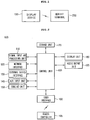
- Fig. 1 is a block diagram illustrating a configuration of a system for transmitting and receiving data, according to an embodiment.
- the system for transmitting and receiving data may include a display device 100 and a mobile terminal 200.
- the display device 100 may be an image display device such as a television (TV), a monitor, a notebook computer, or a tablet Personal Computer (PC) that may be connected to the mobile terminal 200 over a wireless network.
- TV television
- monitor monitor
- notebook computer notebook computer
- PC tablet Personal Computer
- the display device 100 may be a network TV, an Internet Protocol TV (IPTV), a Hybrid Broadcast Broadband TV (HBBTV), or a smart TV that may perform various user-friendly functions as various applications are freely added or deleted to/from a general Operating System (OS) Kernel.
- IPTV Internet Protocol TV
- HBBTV Hybrid Broadcast Broadband TV
- OS Operating System
- the mobile terminal 200 is a device that may be connected to the display device 100 to transmit/receive data over a wireless network.
- the mobile terminal 200 has a screen portion smaller than that of the display device 100, and thus may be a device that is capable of carrying and free moving due to its small size and light weight.
- the mobile terminal 200 may be one of various devices, which may output an image and sound, such as portable phones, smart phones, tablet PCs, digital broadcasting terminals, Personal Digital Assistants (PDAs), Portable Multimedia Players (PMPs), Internet phones such as SoIP, navigation devices, and MP3 players.
- portable phones such as portable phones, smart phones, tablet PCs, digital broadcasting terminals, Personal Digital Assistants (PDAs), Portable Multimedia Players (PMPs), Internet phones such as SoIP, navigation devices, and MP3 players.
- the display device 100 and the mobile terminal 200 may be connected to each other to transmit/receive data in one of various wireless communication schemes such as Wireless LAN (WiFiTM), WiFi direct, WiFi display, BluetoothTM, ZigBeeTM, binary Code Division Multiple Access (CDMA), Wireless broadband (Wibro), World Interoperability for Microwave Access (Wimax), High Speed Downlink Packet Access (HSDPA), Universal Plug and Play (UPnP)/Digital Living Network Alliance (DLBNA), Ultra wide band (UWB)/wireless Universal Serial Bus (USB).
- WiFiTM Wireless LAN
- WiFi direct WiFi direct
- WiFi display BluetoothTM
- ZigBeeTM binary Code Division Multiple Access
- CDMA Code Division Multiple Access
- Wibro Wireless broadband
- WWN World Interoperability for Microwave Access
- HSDPA High Speed Downlink Packet Access
- UPDPA Universal Plug and Play
- UWB Ultra wide band
- USB Universal Serial Bus
- the display device 100 and the mobile terminal 200 may share content by respectively transmitting/receiving their stored data in the above-described wireless communication scheme.
- the content may be real-time broadcast, a movie, music, a photograph, a document file, Content On Demand (COD), a game, news, video call, an application, or the like.
- CDO Content On Demand
- a communication scheme between the display device 100 and the mobile terminal 200 for sharing the content may use various wireless networks enabling data communication, and thus is not limited to a specific communication scheme.
- the mobile terminal 200 and the display device 100 may transmit/receive data to share content. Some embodiments may involve determining whether a mobile terminal and a display device that is physically distinct of the mobile terminal are locationally proximate, and based on a determination that the mobile terminal and the display device are locationally proximate, identifying a first portion of a screen of the display device where the mobile terminal has a high locational proximity relative to at least one other portion of the screen. The determination that the mobile terminal is locationally proximate can involve having the mobile terminal touching the first portion of the screen of the display device. Alternatively, the determination that the mobile terminal is locationally proximate can include the mobile terminal being located within a threshold distance or a predefined distance of the display device.
- a touch between the display device 100 and the mobile terminal 200 is sensed, and thus, content data stored in the display device 100 may be transmitted to the mobile terminal 200 or content data stored in the mobile terminal 200 may be transmitted to the display device 100.
- the display device 100 may include a signal input and processing unit 110, a network interface 120, an external device interface 130, an A/V input unit 140, a sensing unit 150, a control unit 160, a storage unit 170, a display unit 180, an audio output unit 185, and a user interface 190.
- the signal input and processing unit 180 receives and processes a signal from the outside, for example, may select a Radio Frequency (RF) broadcast signal, corresponding to a channel selected by the user or all pre-stored channels, from among a plurality of RF broadcast signals received through an antenna to receive the selected RF broadcast channel.
- RF Radio Frequency
- the network interface 120 may provide an interface for connecting the display device 100 to a wired/wireless network, and transmit/receive data to/from an external device in various wireless communication schemes that have been described above with reference to Fig. 1 .
- the network interface 120 may establish wireless network connection with the mobile terminal 200 according to a communication standard such as WiFi or Bluetooth, and transmit/receive content data and information for data communication to/from the mobile terminal 200 over the connected network.
- a communication standard such as WiFi or Bluetooth
- the network interface 120 may include an Ethernet terminal for accessing Internet, and access a webpage through the Ethernet terminal to receive content data, provided from a specific content provider or a network provider, such as a movie, an advertisement, a game, VOD, a broadcast signal, or the like.
- the external device interface 130 may connect an external device and the display unit 180, for example, access an external device such as a Digital Versatile Disk (DVD), Blu-ray, a game machine, a camera, a camcorder, or a computer (for example, a notebook computer) in a wireless way or a wired way.
- an external device such as a Digital Versatile Disk (DVD), Blu-ray, a game machine, a camera, a camcorder, or a computer (for example, a notebook computer) in a wireless way or a wired way.
- the A/V input unit 140 may include a Composite Video Banking Sync (CVBS) terminal, a component terminal, an S-video terminal (analog), a Digital Visual Interface (DVI) terminal, a High Definition Multimedia Interface (HDMI) terminal, RGB terminals, and a D-SUB terminal.
- CVBS Composite Video Banking Sync
- component terminal an S-video terminal (analog)
- DVI Digital Visual Interface
- HDMI High Definition Multimedia Interface
- RGB terminals a D-SUB terminal.
- the A/V input unit 140 may include a camera or a mike and acquire data corresponding to an image or voice of a user, and the acquired data may be delivered to the control unit 160.
- the sensing unit 150 may include various sensors such as a touch sensor, a magnetometer, an accelerometer, a proximity sensor, a gyroscope sensor, an ambient light sensor, a colorimeter, and a tag, for sensing the current state of the display device 100.
- control unit 160 may sense the touch of the mobile terminal 200 for transmission/reception of data or detect a location/direction where the mobile terminal 200 is touched, by using the measured value of a sensor included in the sensing unit 150
- the control unit 160 controls an overall operation of the display device 100.
- the control unit 160 may demultiplex a data stream that is inputted through the signal input and processing unit 110, the network interface 120, or the external device interface 130, and process the demultiplexed signals, thereby generating and outputting a signal for output of video or audio.
- the storage unit 170 may store a program for the signal processing and control of the control unit 160, and store the signal-processed video, audio, or data signal.
- the storage unit 170 may temporarily store a video, audio, or data signal that is inputted from the external device interface 130 or the network interface 120, or store information regarding a predetermined broadcast channel with a channel storage function.
- the storage unit 170 may store an application or an application list that is inputted from the external device interface 130 or the network interface 120.
- the storage unit 170 may include at least one storage medium of a flash memory, a hard disk, a multimedia card micro type of memory, a card type of memory (for example, an SD or XD memory, etc.), a Random Access Memory (RAM), and a Read Only Memory (ROM, for example, Electrically Erasable and Programmable Read Only Memory (EEPROM), etc.).
- a flash memory for example, a hard disk
- a multimedia card micro type of memory for example, an SD or XD memory, etc.
- RAM Random Access Memory
- ROM Read Only Memory
- EEPROM Electrically Erasable and Programmable Read Only Memory
- the display device 100 may provide content data (for example, a moving image file, a still image file, a music file, a document file, an application file, or the like) stored in the storage unit 170 to a user by replaying the content data.
- content data for example, a moving image file, a still image file, a music file, a document file, an application file, or the like
- the user interface 190 delivers a signal inputted by the user to the control unit 160, or delivers a signal, inputted from the control unit 160, to the user.
- the user interface 190 may receive a control signal or a user input signal such as power-on/off, selection of a channel, or setting of a screen from a remote controller 195 in one of various communication schemes such as Bluetooth, Radio Frequency Identification (RFID), Infrared Data Association (IrDA), Ultra Wideband (UWB), Zigbee, and Digital Living Network Alliance (DLNA) and process the received signal.
- RFID Radio Frequency Identification
- IrDA Infrared Data Association
- UWB Ultra Wideband
- Zigbee Zigbee
- DLNA Digital Living Network Alliance
- the user interface 190 may process the control signal from the control unit 160 in order for the control signal to be transmitted to the remote controller 195.
- the control unit 160 may control the display unit 180 so as to display an image.
- the control unit 160 may perform control such that the display unit 180 displays a broadcast image inputted through the signal input and processing unit 110, an external input image inputted through the external device interface 130, an image inputted through the network interface 120, or an image stored in the storage unit 170.
- An image displayed by the display unit 180 may be a still image or a moving image, and be a Two-Dimensional (2D) image or a Three-Dimensional (3D) image.
- the display unit 180 may form a screen portion that is exposed to the front of the display device 100 for displaying an image.
- the display unit 180 respectively converts an image signal, a data signal, and an On Screen Display (OSD) signal that have been processed by the control unit 160 into RGB signals to generate a driving signal.
- the display unit 180 respectively converts an image signal and a data signal, which are received through the external device interface 130 into RGB signals to generate a driving signal.
- OSD On Screen Display
- the display unit 180 may display an image in one of various display types such as Plasma Display Panel (PDP), Liquid Crystal Display (LCD), Organic Light Emitting Diode (OLED), flexible display, and 3D display.
- PDP Plasma Display Panel
- LCD Liquid Crystal Display
- OLED Organic Light Emitting Diode
- the display unit 180 may be configured with a touch screen and used as an input device instead of an output device.
- the audio output unit 185 receives a signal (for example, a stereo signal, a 3.1 channel signal or a 5.1 channel signal) audio-processed by the control unit 160 to output audio.
- a signal for example, a stereo signal, a 3.1 channel signal or a 5.1 channel signal
- Figs. 2 The configuration of the display device according to an embodiment has been described above with reference to Figs. 2 , but the present invention is not limited thereto.
- the elements of Figs. 2 are partially integrated or omitted, or another element may be added, according to the main function or specification of a display device.
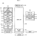
- Fig. 3 is a block diagram illustrating a configuration of a mobile terminal according to an embodiment.
- the mobile terminal 200 may include a wireless communication unit 210, an A/V input unit 220, a user input unit 230, a sensing unit 240, an output unit 250, a memory 260, an interface 270, a control unit 280, and a power supply unit 290.
- the wireless communication unit 210 may an element for wireless communication between the mobile terminal 200 and a wireless communication system, or for wireless communication between the mobile terminal 200 and a network at which the mobile terminal 200 is located.
- the wireless communication unit 210 may include a broadcast reception module 211, a mobile communication module 212, a wireless Ethernet module 213, a Near Field Communication (NFC) module 214, and a location information module 215.
- a broadcast reception module 211 may include a broadcast reception module 211, a mobile communication module 212, a wireless Ethernet module 213, a Near Field Communication (NFC) module 214, and a location information module 215.
- NFC Near Field Communication
- the wireless communication unit 210 may transmit/receive data to/from an external device in one of various wireless communication schemes that have been described above with reference to Fig. 1 .
- the wireless communication unit 210 may establish wireless network connection with the display device 100 according to a communication standard such as WiFi or Bluetooth, and transmit/receive content data and information for data communication to/from the display device 100 over the connected network.
- a communication standard such as WiFi or Bluetooth
- the broadcast reception module 211 receives a broadcast signal and/or broadcast-related information from an external broadcast management server through a broadcast channel.
- the broadcast channel may include a satellite channel and a terrestrial broadcast channel.
- the mobile communication module 211 transmits/receives a wireless signal to/from at least one of a base station, an external terminal, and a server over a mobile communication network.
- the wireless signal may include an audio call signal, a video call signal, or various types of data based on the transmission/reception of a text message or a multimedia message.
- the wireless Ethernet module 213 denotes a module for accessing wireless Internet, and may be implemented as an internal module or an external module.
- the NFC module 214 is a module for NFC, and may use Bluetooth, RFID, IrDA, UWB, or Zigbee.
- the location information module 215 is a module for checking or obtaining the location of a mobile terminal.
- a Global Position System (GPS) module may be used as the location information module 215.
- GPS Global Position System
- the GPS module receives location information from a plurality of satellites.
- the A/V input unit 220 is for inputting an audio signal or a video signal, and may include a camera 221 or a mike 222.
- the camera 221 processes an image frame such as a still image or a moving image, which is obtained by an image sensor in a video call mode or a capture mode.
- the processed image frame may be displayed by the display unit 251.
- the image frame processed by the camera 221 may be stored in the memory 160 or transmitted to the outside through the wireless communication unit 210.
- the camera 221 may be included as two or more according to the configuration aspect of a terminal.
- the mike 222 receives an external sound signal through a microphone and processes the received sound signal into electric audio data, in a call mode or a record mode, or an audio recognition mode.
- the user input unit 230 generates an input data in order for the user to control an operation of a terminal, for which the user input unit 230 may include a key pad, a dome switch, a touch screen (constant pressure/power failure), a jog wheel, and a jog switch.
- the sensing unit 240 may include various sensors such as a touch sensor, a magnetometer, an accelerometer, a proximity sensor, a gyroscope sensor, an ambient light sensor, a colorimeter, and a tag, for sensing the current state of the mobile terminal 200.
- the sensing unit 240 may sense the touch of the display device 100 or detect a location/direction where the mobile terminal 200 is touched, by using the sensor.
- the interface 270 interfaces all external devices connected to the mobile terminal 200.
- the interface 270 may include a wired/wireless headset port, an external charger port, a wired/wireless data port, a memory card port, a port for the connection of a device including an identification module, an audio Input/Output (I/O) port, a video I/O port, and an earphone port.
- I/O audio Input/Output
- the output unit 250 is for inputting an audio signal or a video signal, and may include a display unit 251, a sound output module 252, and an alarm unit 253.
- the display unit 251 displays and outputs information processed by the mobile terminal 200. For example, when the mobile terminal 200 is in the call mode, the display unit 251 displays a User Interface (UI) or a Graphic User Interface (GUI) associated with call. When the mobile terminal 200 is in the video call mode or the capture mode, the display unit 251 displays a captured or/and received image, a UI, or a GUI.
- UI User Interface
- GUI Graphic User Interface
- the sound output module 252 outputs audio data that is received from the wireless communication unit 210 or stored in the memory 260, in a call signal reception mode, a call mode, a record mode, an audio recognition mode, or a broadcast reception mode.
- the memory 260 may store a program for the processing and control of the control unit 280, and temporarily store input/output content data (for example, a moving image file, a still image file, a music file, a document file, an application file, or the like).
- input/output content data for example, a moving image file, a still image file, a music file, a document file, an application file, or the like.
- the control unit 280 controls the overall operation of the mobile terminal 200.
- the control unit 280 performs control and processing related to voice call, data communication, and video call.
- the control unit 280 may include a multimedia module 281 for replaying multimedia content data.
- the multimedia module 281 may be included in the control unit 280, or implemented independently from the control unit 280.
- the power supply unit 290 receives an external power or an internal power to supply a power necessary for an operation of each element, according to the control of the control unit 280.
- Fig. 3 illustrates a mobile terminal including various elements, but the illustrated elements are not all essential elements. That is, the mobile terminal 200 may include elements more than the elements of Fig. 3 , or at least one of the illustrated elements may not be applied.
- the display device 100 and the mobile terminal 200 respectively having the configurations that have been described above with reference to Fig. 3
- the display device 100 and the mobile terminal 200 may perform different functions of transmitting and receiving data according to a direction where the mobile terminal 200 is touched.
- a function of transmitting and receiving data performed between the display device 100 and the mobile terminal 200 may vary according to the orientation (for example, any one of the front, the rear and the side) of the mobile terminal 200.
- data transmitted/received between the display device 100 and the mobile terminal 200 may be processed by different schemes according to a location at which the mobile terminal 200 touches the display device 100.
- Fig. 4 is a flowchart illustrating a method of transmitting and receiving data according to an embodiment, and illustrates a method where the display device 100 controls the transmission/reception of data to/from the mobile terminal.
- the display device 100 establishes network connection with the mobile terminal 200 in operation S300.
- the network interface 120 of the display device 100 may transmit/receive information for network establishment to/from the mobile terminal 200 according to a corresponding communication standard, for data communication with the mobile terminal 200 using a wireless communication scheme such as WiFi, Bluetooth, UPnP/DLBNA, or UWB.
- the network interface 120 may establish wireless network connection on the basis of the transmitted/received network establishment information.
- Network establishment information transmitted/received between the display device 100 and the mobile terminal 200 for the network connection, may include identification (ID) information of each device, ID information regarding a corresponding network, and security information (for example, a password).
- ID identification
- security information for example, a password
- a program for example, a content-sharing application for executing a method of transmitting and receiving data according to an embodiment may be preinstalled in each of the display device 100 and the mobile terminal 200.
- an operation of registering the mobile terminal 200 in the display device 100 may be performed, and also, when the mobile terminal 200 requests network connection, an operation of authenticating the mobile terminal 200 may be further performed on the basis of the registered information.
- the display device 100 and the mobile terminal 200 may search each other and establish network connection.
- the mobile terminal 200 may store a plurality of encryption keys and a Service Set IDentifier (SSID) for WiFi network connected to the display device 100.
- SSID Service Set IDentifier
- Network connection is established, and thereafter, when the mobile terminal 200 touches the screen portion of the display device 100 in operation S310, the display device 100 detects the orientation of the mobile terminal 200 in operation S320.
- the screen portion of the display device 100 may denote a portion of the front of the display device 100 that displays an image when viewed by a user.
- the display unit 180 of the display device 100 may include a display panel (not shown) displaying an image, and a backlight unit (not shown) that is disposed at the rear of the display panel and supplies light to the display panel, in which case the screen portion touching the mobile terminal 200 may denote the front of the display panel.
- the screen portion touching the mobile terminal 200 may denote a functional layer formed at the front of the display panel.
- the mobile terminal 200 touching the screen portion of the display device 100 denotes that the mobile terminal 200 physically touches the screen portion, and may also include a case (which is not the physical touch) where the mobile terminal 200 is very closely adjacent to the screen portion within a touch-detectable distance from the display device 100 or the mobile terminal 200.
- the display unit 180 of the display device 100 may be realized as a touch screen, which may be disposed at the front of the display panel and sense the touch of an object such as a user's finger.
- the touch panel determines the touch location of the object and converts the touch location into an electric signal to output the electric signal.
- the display device 100 may perform a function corresponding to the touch location.
- the touch panel may include a plurality of touch sensors for sensing the touch and touch location of the object, and the touch sensors may sense a touch in a resistive touch scheme, a light sensing touch scheme, or a capacitive touch scheme.
- a capacitive touch panel may sense the change of a capacitance that is formed by a conductive sensing pattern and another ambient sensing pattern or a ground electrode when touched by a user's finger or an object, and thus converts a touch location into an electric signal.
- the display device 100 may sense the touch and touch location of the mobile terminal with the touch panel included in the display unit 180.
- the sensing unit 150 of the display device 100 may detect the orientation of the mobile terminal 200 by using various sensors such as a magnetometer, an accelerometer, a proximity sensor, a gyroscope sensor, an ambient light sensor, and a colorimeter.
- sensors such as a magnetometer, an accelerometer, a proximity sensor, a gyroscope sensor, an ambient light sensor, and a colorimeter.
- the sensing unit 150 may detect in which direction of the front, the rear, and the side the mobile terminal 200 is touched.
- the control unit 160 of the display device 100 may determine the orientation of the mobile terminal 200 by using a sensing value outputted from the sensing unit 150. Also, the control unit 160 may use the sensing value of the sensing unit 150 and information received from the mobile terminal 200, for determining the orientation. The information received from the mobile terminal 200 may be a sensing value measured by the sensing unit 240 of the mobile terminal 200.
- the orientation of the mobile terminal 200 may be detected by the sensing unit 240 of the mobile terminal 200 or the control unit 280, in which case information regarding the orientation of the mobile terminal 200 may be received by the display device 100 over the network that has been connected in operation S300.
- the display device 100 transmits/receives data to/from the mobile terminal 200 according to the orientation of the mobile terminal 200 in operation S330.
- the function of transmitting and receiving data performed in operation S300 may vary according to the detected orientation of the mobile terminal 200, and thus, by changing the orientation of the mobile terminal 200, the user may perform control such that a desired function of transmitting and receiving data is performed between the display device 100 and the mobile terminal 200.
- one of predetermined first and second functions of transmitting and receiving data may be performed between the display device 100 and the mobile terminal 200 according to whether the orientation of the mobile terminal 200 is the front or the rear.
- data may be transmitted from the mobile terminal 200 to the display device 100.
- the first surface may be the front of the mobile terminal 200
- the second surface may be the rear of the mobile terminal 200.
- the method of transmitting and receiving data according to an embodiment has been described above as an example when the first surface is the front of the mobile terminal 200 and the second surface is the rear of the mobile terminal, but the present invention is not limited thereto.
- the first surface may be the rear of the mobile terminal 200, and the second surface may be the front of the mobile terminal 200.
- one of the first and second surfaces may be the side of the mobile terminal 200.
- the display device 100 processes the transmitted/received data according to the detected touch location of the mobile terminal 200 in operation S340.
- control unit 160 of the display device 100 may determine whether the touch location of the mobile terminal 200 detected in operation S320 is a location of the screen of the display device 100 displaying a representation of the content data.
- the control unit 160 allows content data received from the mobile terminal 200 to be displayed at the touch location.
- control unit 160 may allow content data received from the mobile terminal 200 to be displayed at the touch location in association with representation of the content data displayed on the screen of the display device 100.
- content data that is selected from among contents displayed on the screen of the display device 100 by a user may be transmitted to the mobile terminal 200, and the transmitted content data may be continuously stored in the display device 100.
- content data displayed at the touch location may be transmitted to the mobile terminal 200, and the content data transmitted to the mobile terminal 200 may be deleted from the storage unit 170.
- a display unit 251 displaying an image is disposed at the front 200F of the mobile terminal 200.
- the rear 200R of the mobile terminal 200 may be covered by a case.
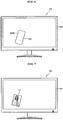
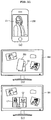
- the user may move the mobile terminal 200 such that the front 200F of the mobile terminal 200 is oriented to the display device 100, and thus touch the front 200F of the mobile terminal 200 to the screen portion 181 of the display device 100.
- data stored in the mobile terminal 200 may be transmitted to the display device 100 over the connected network, and the data transmitted to the display device 100 may include content data that is selected from the mobile terminal 200 by the user.
- the data of photograph C1 transmitted to the display device 100 may be outputted by the display unit 180, and the photograph C1 may be displayed in a region corresponding to the touch location of the mobile terminal 200.
- the user may move the mobile terminal 200 such that the rear 200R of the mobile terminal 200 is oriented to the display device 100, and thus touch the rear 200R of the mobile terminal 200 to the screen portion 181 of the display device 100.
- data stored in the mobile terminal 200 may be transmitted to the display device 100 over the connected network, and the data transmitted to the display device 100 may include content data that is selected from among contents stored in the display device 100 by the user.
- the data of photograph C2 transmitted to the mobile terminal 200 may be outputted by the display unit 251, and the photograph C2 may be displayed on the screen of the mobile terminal 200.
- data transmitted from the display device 100 to the mobile terminal 200 may include a representation of content data that is displayed at a location of the screen portion 181 of the display device 100 which is touched by the mobile terminal 200.
- the method of transmitting and receiving data has been described above with reference to Figs. 5 to 9 as an example when the display device 100 and the mobile terminal 200 share the photograph, but the present invention is not limited thereto.
- the display device 100 and the mobile terminal 200 may share various contents such as a moving image, music, an application, contact information, a video streaming service, video call, a game, and news, in addition to the photograph.
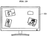
- a plurality of images may be displayed on the screen portion 181 of the display device 100, and the images may respectively represent contents stored in the display device 100.
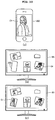
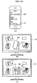
- Fig. 10 when the user touches the front 200F of the mobile terminal 200, displaying the photograph C1 on its screen, to a region of the screen portion 181 of the display device 100 not displaying a representation of content data, data including the photograph C1 may be transmitted from the mobile terminal 200 to the display device 100, and thus, the photograph C1 may be displayed in a location of the screen portion 181 of the display device 100 corresponding to the touched location.
- the photograph C1 may be displayed greater than displayed by the mobile terminal 200 in size, on the screen of the display device 100.
- the mobile terminal 200 may enlarge the photograph C1 at a certain ratio and transmit the enlarged photograph to the display device 100.
- a state (for example, an entire photograph C1 data-to-currently transmitted data ratio) where data is transmitted from the mobile terminal 200 to the display device 100 may be displayed on the screen of the display device 100 by using a progressive bar.
- the enlarged and displayed photograph C1 may be reduced and displayed in a thumbnail icon type, on the screen of the display device 100.
- the photograph C1 may be enlarged and displayed on an original-size screen or the entire screen.
- Fig. 11 when the user touches the front 200F of the mobile terminal 200, displaying the photograph C1 on its screen, to a region of the screen portion 181 of the display device 100 displaying the photograph C2, data including the photograph C1 may be transmitted from the mobile terminal 200 to the display device 100, and the photograph C1 may be displayed in combination with the displayed photograph C2 together, at the touch location.
- a region of the screen portion 181 of the display device 100 not displaying a representation of content data data including the contact information C6 may be transmitted from the mobile terminal 200 to the display device 100, and the contact information C6 may be displayed in a region of the screen portion 181 of the display device 100 corresponding to the touch location.
- contact information received from the mobile terminal 200 may be displayed in association with the photograph C2 displayed at the touch location of the mobile terminal 200.
- the contact information C6 displayed by the mobile terminal 200 may be mapped to the photograph C2 stored in the display device 100.
- the contact information mapped to the photograph C2 is configured as icons by items, and displayed adjacently to each other on the screen of the display device 100 together with the photograph C2.
- a mobile phone number in the contact information C6 displayed by the mobile terminal 200 is displayed as a first icon C6a
- an email address in the contact information C6 is displayed as a second icon C6b
- a user ID of a Social Network Service (SNS) is displayed as a third icon C6c.
- SNS Social Network Service
- the user may simultaneously check the photograph and contact information of a specific person by using the icons C6a to C6c that are mapped to the photograph C2 and displayed, and select one of the icons C6a to C6c to approach a contact item corresponding to a pertinent item.
- the user may drag the photograph the photograph C1 (or a thumbnail icon indicating a corresponding photograph) displayed by the display device 100 and drop the dragged photograph into a region displaying the email icon C6b mapped to the photograph C2.
- data including the dragged photograph C1 may be transmitted to an email address (i.e., ab@x.com) corresponding to the email icon C6b.
- a method of displaying contact information illustrated in Fig 14 is merely an embodiment, but the present invention is not limited thereto.
- the contact information may be mapped to content data stored in the display device 100 and displayed in various types.
- Figs. 15 to 19 are views illustrating embodiments of a method which transmits content data stored in the display device 100 to a mobile terminal.
- the mobile terminal 200 may display the photograph C1.
- the user may select two or more contents displayed on the screen of the display device 100, and transmit the selected contents to the mobile terminal 200.
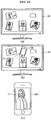
- a portion (a) and portion (b) of Fig. 16 when the user touches the rear 200R of the mobile terminal 200 to a region of the screen portion 181 of the display device 100 not displaying a representation of content data and then selects the photographs C1 and C2 and music C4 displayed on the screen of the display device 100 to drag corresponding images to a location touched by the mobile terminal 200 with three fingers, data of the selected photographs C1 and C2 and music C4 may be transmitted to the mobile terminal 200.
- the content data transmitted to the mobile terminal 200 may be continuously stored without being deleted from the storage unit 170 of the display device 100.
- an image for the transmitted content data may be continuously displayed on the screen of the display device 100, and an image dragged to the touch location of the mobile terminal 200 may be a virtual image for a corresponding content data.
- the photograph C1 may not be deleted from the display device 100, and an image corresponding to the photograph C1 may be continuously displayed on the screen of the display device 100.
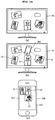
- the user may select one or more contents, intended to be transmitted to the mobile terminal 200, from among contents stored in the display device 100, and thereafter touch the rear 200R of the mobile terminal 200 to a region of the screen portion 181 of the display device 100 displaying the representation of content data, thereby allowing the selected content data to be transmitted from the display device 100 to the mobile terminal 200.
- the display device 100 may detect a location touched by the rear 200R of the mobile terminal 200 and then transmit data, including content data displayed at the detected touch location, to the mobile terminal 200.
- the photograph C2 displayed at the touch location of the mobile terminal 200 may be transmitted to the mobile terminal 200 and simultaneously deleted from the storage unit 170 of the display device 100.
- the photograph C2 transmitted to the mobile terminal 200 is no longer displayed on the screen of the display device 100.
- content data corresponding to the touch location of the mobile terminal 200 may be selected.
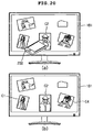
- Fig. 20 illustrates an embodiment of a method which selects specific content data stored in a display device with a mobile terminal.
- Fig. 21 illustrates an embodiment of a method which selects a plurality of contents stored in a display device with a mobile terminal.
- the user may move the mobile terminal 200 to the display device 100 in an askew direction instead of the front or the rear, and touch the side of the mobile terminal 200 to the screen 181.
- content data corresponding to a location touched by the side of the mobile terminal 200 may be selected from among contents displayed on the screen of the display device 100 by the user.
- the photograph C2 may be selected from among contents stored in the display device 100.
- the display device 100 may include a touch screen, and detect whether the mobile terminal 200 touches the display device 100 and a touch location with the touch screen.
- a registration process and an authentication process for the mobile terminal 200 may be performed before performing the method of transmitting and receiving data that has been described above with reference to Figs. 4 to 21 .
- the registration process is an operation that stores the identification information of the mobile terminal 200 in the display device 100 to authorize the sharing of content data with the display device 100.
- the authentication process is an operation that checks whether a corresponding device has been registered in the mobile terminal 200 that approaches the display device 100 for sharing content data.
- the display device 100 includes a Frequency Modulation (FM) transmitter 300, which may transmit an FM signal including registration information over an FM frequency band.
- FM Frequency Modulation
- the FM transmitter 300 may scan a plurality of FM frequency bands, and transmit a Radio Data System (RDS) signal, including a password and identification information (for example, network ID) for a wireless network, over an FM frequency band in a carousel scheme.
- RDS Radio Data System
- the RDS signal may have identification information for identifying data included in the RDS payload.
- the RDS signal transmitted from the FM transmitter 300 may include a unique identifier, as a bit sequence (ID), for identifying the registration information.
- ID bit sequence
- the network identification information (for example, the network ID) and password included in the RDS signal is encrypted
- the mobile terminal 200 may store a plurality of keys for decrypting the encrypted network identification information (for example, the network ID) and password.
- the encryption keys may be changed for security with the elapse of time, and the changed encryption key may be pre-provided to the display device 100 and the mobile terminal 200.
- identification information (ID) for the mobile terminal 200 may be given, and the mobile terminal 200 may scan an FS spectrum.
- the mobile terminal 200 may check a unique ID bit sequence included in the RDS payload to detect the RDS signal transmitted from the display device 100.
- the mobile terminal 200 extracts the encrypted network ID and password from the detected RDS signal, and decrypt the encrypted network ID and password with a priori key.
- the mobile terminal 200 may establish wireless network connection with the display device 100 by using the decrypted network ID and password.
- the mobile terminal 200 may transmit the identification information (ID) of the mobile terminal 200 and user information (for example, a user name, a photograph, etc.) to the display device 100 over the connected network.
- ID identification information
- user information for example, a user name, a photograph, etc.
- the display device 100 may store the identification information (ID) of the mobile terminal 200 received from the mobile terminal 200 to register a corresponding terminal.
- ID identification information
- the mobile terminal 200 may provide the message.
- a wireless network for connecting the display device 100 and the mobile terminal 200 may be based on a WiFi wireless communication standard, and thus, registration information transmitted using an RDS signal may include an ID and password of a WiFi network.
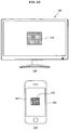
- the above-described registration information may be transferred from the display device 100 to the mobile terminal 200 through a pattern 310 using a steganography mechanism.
- the display device 100 may display the pattern 310 including encrypted information for network establishment.
- the user may focus a camera (not shown), included in the mobile terminal 200, on the pattern 310 to allow the pattern 310 to be displayed on a screen 251 of the mobile terminal 200.
- the mobile terminal 200 may collect information (for example, a WiFi network ID and a password) for network establishment from an image of the acquired pattern 310, and establish wireless network connection with the display device 100 on the basis of the collected information.
- information for example, a WiFi network ID and a password
- the mobile terminal 200 may transmit its identification information (for example, a model number or International Mobile Equipment Identity (IMEI) serial) to the display device 100 over the connected wireless network, and the transmitted identification information of the mobile terminal 200 may be stored and registered in the display device 100.
- IMEI International Mobile Equipment Identity
- the registration process and authentication process for the mobile terminal 200 are performed, and thereafter, when the mobile terminal 200 touches the screen portion 181 of the display device 100, as described above with reference to Figs. 4 to 21 , different functions of transmitting and receiving data may be performed between the display device 100 and the mobile terminal 200 according to the orientation of the mobile terminal 200.
- the mobile terminal 200 may include a magnetometer.
- the mobile terminal 200 may detect the orientation with the magnetometer and transmit information regarding the orientation to the display device 100.
- the mobile terminal 200 may determine the orientation as the front when an output value of the magnetometer indicates 108 degrees or more, and transmit information indicating "the orientation is the front" to the display device 100.
- the display device 100 may request the transmission of content data to the mobile terminal 200 on the basis of the received information regarding the orientation, and receive content data selected by the mobile terminal 200.
- the mobile terminal 200 may determine the orientation as the rear when the output value of the magnetometer indicates less than 108 degrees, and transmit information indicating "the orientation is the rear" to the display device 100.
- the display device 100 may transmit content data to the mobile terminal 200 on the basis of the received information regarding the orientation.
- the detected orientation of the mobile terminal 200 and the identification information (ID) of the mobile terminal 200 may be stored and managed in the display device 100.
- the mobile terminal 200 may include an accelerometer.
- the mobile terminal 200 may detect the orientation by using an output value of the accelerometer.
- a value that the accelerometer measures along an moving axis of the mobile terminal 200 when the orientation is the front is opposite to a value that the accelerometer measures along the moving axis of the mobile terminal 200 when the orientation is the rear, and thus, the mobile terminal 200 may detect the orientation by using the output value of the accelerometer.
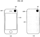
- the mobile terminal 200 may detect an orientation toward the display device 100 by using proximity sensors 320 and 321 respectively disposed in the front 200F and the rear 200R.
- the proximity sensor 320 disposed in the front 200F of the mobile terminal 200 may sense the approach of an object
- the proximity sensor 321 disposed in the rear 200R of the mobile terminal 200 may sense the approach of an object
- the mobile terminal 200 may detect an orientation toward the display device 100 by using a gyroscope sensor.
- Each of the display device 100 and the mobile terminal 200 includes a gyroscope sensor.
- the display device 100 may receive a specific value of the gyroscope sensor, included in the mobile terminal 200, from the mobile terminal 200 and compare the received value with a measurement value of the internal gyroscope sensor to detect the orientation of the mobile terminal 200.
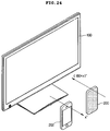
- the display device 100 may compare an xyz axis (g1), indicating the direction of the display device 100 detected by the internal gyroscope sensor, and an xyz axis (g2), indicating the direction of the mobile terminal 200 detected by the gyroscope sensor of the mobile terminal 200, to detect the orientation.
- an xyz axis (g1) indicating the direction of the display device 100 detected by the internal gyroscope sensor
- g2 xyz axis
- the display device 100 may determine as touched by the rear of the mobile terminal 200.
- the display device 100 may determine as touched by the front of the mobile terminal 200.
- the display device 100 may determine as touched by the side of the mobile terminal 200.
- the mobile terminal 200 may sense an orientation toward the display device 100 by using a light sensor 330, which may be implemented with an ambient light sensor or a colorimeter.
- the mobile terminal 200 may transmit color information, which has been measured by the light sensor 330 disposed in the front 200F, and the identification information (ID) of the mobile terminal 200 to the display device 100.
- the display device 100 may compare color information of an image, displayed at a time when the mobile terminal 200 touches the display device 100, and the color information received from the mobile terminal 200 to determine the orientation.
- the light sensor 330 disposed in the front 200F of the mobile terminal 200 may sense an image displayed by the display device 100, and thus, color information measured by the light sensor 330 may match with color information of the image displayed by the display device 100.
- the display device 100 may determine as touched by the front of the mobile terminal 200.
- a color temperature for example, a color temperature of a region corresponding to a location touched by the mobile terminal 200, in the displayed image
- the display device 100 may determine as touched by the front of the mobile terminal 200.
- the display device 100 may acquire color information of an image, displayed at the touched time, from display image data and store the acquired color information in the storage unit 170.
- color information measured by the light sensor 330 may differ from color information of an image displayed by the display device 100.
- the display device 100 may determine as touched by the rear of the mobile terminal 200.
- a color temperature for example, a color temperature of a region corresponding to a location touched by the mobile terminal 200, in the displayed image
- the display device 100 may determine as touched by the rear of the mobile terminal 200.
- one or more conductors are attached to each of the front and rear of the mobile terminal 200, and the touch of the mobile terminal 200 may be sensed with the conductors.
- the mobile terminal 200 may sense a current, flowing through the conductors in the front, to detect that the front of the mobile terminal 200 has touched the display device 100.
- the mobile terminal 200 may sense a current, flowing through the conductors in the rear, to detect that the rear of the mobile terminal 200 has touched the display device 100.
- the mobile terminal 200 may include a gyroscope sensor and an accelerometer.
- the mobile terminal 200 may detect the orientation with a three-axis gyroscope sensor and a two-axis gyroscope sensor, and then transmit information regarding the detected orientation to the display device 100.
- a display device 100 according to the second embodiment may include a plurality of Near Field Communication (NFC) tags, which may be used to detect whether the mobile terminal 200 touches the display device 100 and the touch location of the mobile terminal 200.
- NFC Near Field Communication
- NFC is a branch of RFID, and is a near field wireless communication scheme that has been defined as a standard in ISO 18902 for transmitting low-power data at a frequency of 13.56 MHz in a near field. Also, NFC may perform near field wireless communication at various frequency bands such as 125 KHz, 135 KHz and 900 MHz, in addition to a frequency of 13.56 MHz.
- the display device 100 may include a plurality of NFC tags 400 disposed in the rear of the display unit 180.
- the NFC tag 400 may be a passive NFC tag.
- the NFC tag 400 may store manufacturer information regarding the display device 100, a model name, a model number, identification information (for example, a serial number) of a corresponding device, and a tag index for identifying a location at which a corresponding NFC tag is disposed.
- the tag index may represent the location of the NFC tag 400 as a coordinate (x, y).
- the serial number among the information stored in the NFC tag 400 varies per display device and is used to identify a corresponding display device 100.
- the tag index varies per NFC tag and is used to identify the location of a corresponding NFC tag 400.
- the mobile terminal 200 may include an NFC reader 410.
- the NFC reader 410 may transmit a power and a signal to the NFC tag 400 included in the display device 100 to activate the NFC tag by using a signal of a certain frequency band (for example, a frequency band of 13.56 MHz), and may read data stored in the activated tag 400.
- a signal of a certain frequency band for example, a frequency band of 13.56 MHz
- the NFC reader 410 included in the mobile terminal 200 may read data from an NFC tag that is located in a certain distance, for example, about 4cm, from the mobile terminal 200.
- the NFC reader 410 included in the mobile terminal 200 may receive information stored in the NFC tag.
- the NFC reader 200 included in the mobile terminal 200 may read information that is stored in a plurality of NFC tags 401 to 406, disposed in a touch region R of the mobile terminal 200, among a plurality of NFC tags.
- the mobile terminal 200 may check manufacturer information, a model name, a model number, and a serial number that are read with the NFC reader 410, and detect that the mobile terminal 200 has touched the display device 100.
- a distance from the front of the display device 100 to the NFC tag 400 may be set to a certain distance (for example, 4cm) within which data stored in the NFC tag 400 may be read, or a value slightly greater than the certain distance.
- the thickness (for example, a sum of the thicknesses of the display panel and backlight unit) of the display unit 180 may have the certain distance or a value slightly greater than the certain distance.
- the mobile terminal 200 may detect the touch location with a tag index that is read with the NFC reader 410.
- the mobile terminal 200 touching the display device 100 may read a tad index from each of the NFC tags 401 to 406 disposed in the touch region R, and detect a location, touched by the mobile terminal 200, with coordinates (x, y) of the read tag indexes.
- Data stored in the NFC tags 400 may be a plurality of UPnP device description parameters, respectively.
- the mobile terminal 200 may detect whether the touch occurs and a touch location by using the UPnP device description parameters that are read from the NFC tag 400 with the NFC reader 410.
- the UPnP device description parameters may be used to the above-described registration and authentication operations for the mobile terminal 200.
- the display device 100 may read data (for example, the UPnP device description parameters), stored in an RFID tag 430 of the mobile terminal 200, with a plurality of RFID readers 420 to 423 disposed at an edge portion.
- data for example, the UPnP device description parameters
- the display device 100 may compare the intensities of respective RF signals received from the RFID readers 420 to 423 to detect the touch location of the mobile terminal 200.
- the touch location of the mobile terminal 200 may be determined as the center portion of the display device 100, and as the intensity of an RF signal received from a specific RFID reader becomes greater, the touch location may be moved to be adjacent to a corresponding RFID reader.
- an RFID reader 440 is included in the display device 100, and the RFID tag 430 is included in the mobile terminal 200. Therefore, the display device 100 and the mobile terminal 200 may perform the operations that have been described above with reference to Figs. 31 to 33 , respectively.
- the display device 100 may receive a plurality of sensing values (for example, information regarding the orientation of the mobile terminal 200 or an output value of a sensor for sensing the orientation) measured by the sensing unit 240 of the mobile terminal 200, in the RFID near field wireless communication scheme that has been described above with reference to Figs. 31 to 33 .
- a plurality of sensing values for example, information regarding the orientation of the mobile terminal 200 or an output value of a sensor for sensing the orientation
- Figs. 35 to 41 are views illustrating a third embodiment of each of a mobile terminal and a display device which perform a method of transmitting and receiving data according to an embodiment.
- a touch location and orientation of the mobile terminal may be detected with a catadioptric camera included in the display device 100.
- a plurality of catadioptric cameras 500 to 530 may be installed at an edge portion of the display device 100.
- the catadioptric camera 500 may include a catadioptric reflector 501 having a low profile, and a camera 502 having a special lens system.
- the catadioptric reflector 501 may be implemented with a convex mirror having a certain focus length.
- the display device 100 may acquire an image of the screen portion from four different perspectives, with the catadioptric cameras 500 to 530 having the above-described configuration, and thus may secure a field of view as illustrated in Fig. 37 .
- Fig. 38 when a user moves the front of the mobile terminal 200 toward the display device 100 and the mobile terminal 200 lies within a field of view of each of the catadioptric cameras 500 to 530 illustrated in Fig. 37 , cameras 212f and 212r respectively disposed in the front and rear of the mobile terminal 200 may operate, and thus, the display device 100 and the mobile terminal 200 may recognize each other with the catadioptric cameras 500 to 530 and the front camera 212f.
- the mobile terminal 200 may determine the orientation of the mobile terminal 200 as the front by using the image of the display device 100 that has been acquired with the front camera 212f, or the display device 100 may determine the orientation as the front by using the image (for example, a front shape of the mobile terminal 200) of the mobile terminal 200 that has been acquired with the catadioptric cameras 500 to 530.
- the display device 100 and the mobile terminal 200 may recognize each other with the catadioptric cameras 500 to 530 and the rear camera 212r.
- the mobile terminal 200 may determine the orientation of the mobile terminal 200 as the rear by using the image of the display device 100 that has been acquired with the rear camera 212r, or the display device 100 may determine the orientation as the rear by using the image (for example, a rear shape of the mobile terminal 200) of the mobile terminal 200 that has been acquired with the catadioptric cameras 500 to 530.
- the display device 100 and the mobile terminal 200 may recognize each other with the catadioptric cameras 500 to 530, the front camera 212f, and the rear camera 212r.
- the mobile terminal 200 may determine the orientation of the mobile terminal 200 as the side by using the image of the display device 100 that has been acquired with the front camera 212f and the rear camera 212r, or the display device 100 may determine the orientation as the side by using the image (for example, a front shape and rear shape of the mobile terminal 200) of the mobile terminal 200 that has been acquired with the catadioptric cameras 500 to 530.
- the magnetometer, accelerometer, proximity sensor, gyroscope sensor, ambient light sensor, or colorimeter included in the mobile terminal 200 may operate, and thus, the orientation may be detected by the above-described scheme.
- the display device 100 may detect the orientation of the mobile terminal 200 by using an image that is acquired with the catadioptric cameras 500 to 530.
- a distance d(x) from the optical axis of the catadioptric camera 500 to a touch point P may be calculated with a distance 'x' on an image plane and an angle ( ⁇ ) of a line vertical to the convex mirror.
- the display device 100 may determine the touch location of the mobile terminal 200 with the calculated distances d(x).
- the display device 100 may detect whether the mobile terminal 200 touches the display device 100 and the touch location of the mobile terminal 200 by using a plurality of light sources (for example, IR LED emitters) disposed at respective edge portions and a plurality of IR photodetectors.
- a plurality of light sources for example, IR LED emitters
- the method of transmitting and receiving data may be manufactured as programs executable in computers and be stored in a computer readable recording medium.
- Examples of the computer readable recording medium include read-only memory (ROM), random-access memory (RAM), CD-ROMs, magnetic tapes, floppy disks, optical data storage devices, and carrier waves (such as data transmission through the Internet).
- the computer readable recording medium can be distributed over network coupled computer systems so that the computer readable code is stored and executed in a distributed fashion. Also, functional programs, codes, and code segments for accomplishing the present invention can be easily construed by programmers skilled in the art to which the present invention pertains.
- the mobile terminal in a case where data is transmitted/received between the display device and the mobile terminal, the mobile terminal differently processes transmitted/received data according to a location at which the mobile terminal touches the screen portion of the display device, and thus, provided can be an intuitive user interface that may allow a user to easily control the transmission/reception of data between the display device and the mobile terminal.
Landscapes
- Engineering & Computer Science (AREA)
- Signal Processing (AREA)
- Multimedia (AREA)
- Computer Networks & Wireless Communication (AREA)
- Human Computer Interaction (AREA)
- General Engineering & Computer Science (AREA)
- Databases & Information Systems (AREA)
- Theoretical Computer Science (AREA)
- Life Sciences & Earth Sciences (AREA)
- Environmental Sciences (AREA)
- General Physics & Mathematics (AREA)
- Business, Economics & Management (AREA)
- Physics & Mathematics (AREA)
- Biodiversity & Conservation Biology (AREA)
- Ecology (AREA)
- Emergency Management (AREA)
- Environmental & Geological Engineering (AREA)
- Automation & Control Theory (AREA)
- Remote Sensing (AREA)
- Software Systems (AREA)
- User Interface Of Digital Computer (AREA)
- Controls And Circuits For Display Device (AREA)
- Information Transfer Between Computers (AREA)
- Telephone Function (AREA)
- Two-Way Televisions, Distribution Of Moving Picture Or The Like (AREA)
Description
- The present application claims priority to Korean Patent Application No.
10-2011-0061963, filed on June 24, 2011 U.S. Patent Application Serial No. 61/442,810, filed on February 15, 2011 - The present disclosure relates to a method of transmitting and receiving data between a display device and a mobile terminal.
- Mobile terminals are portable devices that are capable of carrying and have at least one of: a function of performing voice call and video call; a function of inputting/outputting information; and a function of storing data.
- As the functions of the mobile terminals are further diversified, the mobile terminals progressively have a plurality of complicated functions such as a function of capturing a picture or a moving image, a function of replaying a music file or a video file, a function of playing a game, a function of receiving broadcast, a function of accessing wireless Internet, etc. That is, the mobile terminals are realized as multimedia players.
- "ThinSight: Versatile multi-touch sensing for thin form-factor displays", Hodges et.al., CONFERENCE ON HUMAN FACTORS IN COMPUTING SYSTEMS, PROCEEDINGS OF THE SIGCHI CONFERENCE ON HUMAN FACTORS IN COMPUTING SYSTEMS 2007, 7 October 2007, pages 259-268, may be construed to disclose an optical sensing system, fully integrated into a thin form factor display, capable of detecting multiple fingers placed on or near the display surface. The display is embedded behind a regular LCD, allowing sensing without degradation of display capability. Fingertips and hands are clearly identifiable through the display. The approach of optical sensing also opens up the possibility for detecting other physical objects and visual markers through the display, and some initial experiments are described. There are considerations on: interaction at a distance using IR pointing devices, and IR-based communication with other electronic devices through the display.
-
WO 2010/096128 A1 may be construed to disclose a technique, in which a surface computing environment users are provided a seamless and intuitive manner of modifying security levels associated with information. If a modification is to be made the user can perceive the modifications and the result of such modifications, such as on a display. When information is rendered within the surface computing environment and a condition changes, the user can quickly have that information concealed in order to mitigate unauthorized access to the information. - Embodiments provide a user interface which can efficiently control data communication between a display device and a mobile terminal. There are provided a method, an apparatus and a computer program product according to the independent claims. Developments are set forth in the dependent claims
- Preferably, there is a method of facilitating communications between at least one mobile terminal and a display device. The method comprises determining whether a mobile terminal and a display device that is physically distinct of the mobile terminal are locationally proximate, and based on a determination that the mobile terminal and the display device are locationally proximate, identifying a first portion of a screen of the display device where the mobile terminal has a high locational proximity relative to at least one other portion of the screen. The method includes determining whether the identified first portion of the screen is displaying a representation of content data. Based on the determination that the identified first portion is displaying the representation of the content data, the method preferably involves accessing the content data at the first portion of the display device, transferring the accessed content data from the display device to the mobile terminal, and based upon the transfer of the content data, updating the representation of the content data on the display device.
- Preferably, the method can include wirelessly communicating the content data between the mobile terminal and the display device. The determination that the mobile terminal is locationally proximate can involve having the mobile terminal touching the first portion of the screen of the display device. The determination that the mobile terminal is locationally proximate can include the mobile terminal being located within a predefined distance of the display device. The method can involve determining information for at least one of a location of the mobile terminal with respect to the display device and an orientation of the mobile terminal with respect to the display device. The method can involve processing the content data related to at least one of the location and orientation of the mobile terminal with respect to the display device. The display device can be untethered with respect to the mobile terminal, where the display device and the mobile terminal can be electrically disconnected with respect to each other. The method can involve wirelessly transferring the content data based on at least one of a location and an orientation of the mobile terminal with respect to the display device. The method can involve the following features: determining whether the orientation of the mobile terminal has at least one of a first side facing the screen of the display device and a second side facing away from the screen of the display device, wherein the first side of the mobile terminal comprises a display screen, and responsive to determining that the orientation of the mobile terminal has the second side facing away the screen of the display device, performing the transferring of the content data from the display device to the mobile terminal. The transfer of the content data from the display device to the mobile terminal can commence when the mobile terminal ceases to be within the locational proximity of the display device. The transfer of the content data from the display device to the mobile terminal can commence when the mobile terminal ceases to touch the screen of the display device. The method can involve performing a copy operation, where the copy operation can involve copying the content data from a storage unit of the display device to the mobile terminal. The method can involve performing a cut operation, where the cut operation can include removing the display of the representation of the content data from the first portion of the screen of the display device. The method can involve deleting the content data from a storage unit of the display device. The method may involve the following operations: transferring a copy of the content data from the display device to the mobile terminal, and deleting the content data from a storage unit of the display device immediately after the content data is transferred to the mobile terminal. The content data can include at least one of video, text, audio, a photograph, a document file, a game, a representation of a telephone call or a video call, and a software application. The determination of the first portion of the screen of the display device where the mobile terminal is locationally proximate with the display device can involve detecting a touch location of the display device where a rear side of the mobile terminal touches the display device. The determination of the first portion of the screen of the display device where the mobile terminal is locationally proximate with the display device can involve determining a touch location of the mobile terminal with respect to the first portion of the screen of the display device by using at least one of a touch sensor, an Near Field Communication (NFC) tag, and a catadioptric camera in the display device. The determination of the touch location can involve detecting a proximity of at least one NFC tag, from which an NFC reader comprised in the mobile terminal has read information, from among a plurality of NFC tags disposed in a rear side of a screen portion of the display device, and determining the touch location of the mobile terminal on the display device based on a location of the detected NFC tag. The determination of the touch location can involve determining the touch location of the mobile terminal by using respective images captured by a plurality of catadioptric cameras on the display device that are located at front edges of the screen of the display device.
- Preferably, there is a method of facilitating communications between at least one mobile terminal and a display device. The method includes determining whether a mobile terminal and a display device that is physically distinct of the mobile terminal are locationally proximate, and based on a determination that the mobile terminal and the display device are locationally proximate, identifying a first portion of a screen of the display device where the mobile terminal has a high locational proximity relative to at least one other portion of the screen. The method involves determining whether the identified first portion of the screen is displaying a representation of content data, and based on the determination that the first portion of the screen is not displaying the content data, detecting a user input to move content data represented at a second portion of the screen of the display device to the identified first portion of the screen of the display device. In response to detecting the user input, the method involves accessing the content data that is represented at the second portion of the screen of the display device, transferring the accessed content data from the display device to the mobile terminal, and updating the representation of the content data on the display device.
- Preferably, the user input can include a touch command on the screen of the display device. The method can involve wirelessly communicating the content data between the mobile terminal and the display device. The determination that the mobile terminal is locationally proximate can involve having the mobile terminal to physically touch the first portion of the screen of the display device. The determination that the mobile terminal is locationally proximate can involve the mobile terminal being located within a threshold distance or a predefined distance of the display device. The method can involve determining information for at least one of a location of the mobile terminal with respect to the display device and an orientation of the mobile terminal with respect to the display device, and wirelessly transferring the content data based on at least one of a location and an orientation of the mobile terminal with respect to the display device. The method can involve determining whether the orientation of the mobile terminal has at least one of a first side facing the screen of the display device and a second side facing away from the screen of the display device, where the first side of the mobile terminal includes a display screen, and responsive to determining that the orientation of the mobile terminal has the second side facing away the display of the display device, performing the identification of the first portion of the screen. The transfer of the content data from the display device to the mobile terminal can commence when the user input is detected. The method can involve performing a copy operation, where the copy operation can include copying the content data from a storage unit of the display device to the mobile terminal. The method can involve: detecting a second user input to move second content data represented at a third portion of the screen of the display device to the identified first portion of the screen of the display device; and in response to detecting the second user input: accessing the second content data that is represented at the third portion of the screen of the display device; transferring the accessed second content data from the display device to the mobile terminal; and updating the representation of the second content data on the display device. The content data can include at least one of video, text, audio, a photograph, a document file, a game, a representation of a telephone call or a video call, and a software application.
- Preferably, there is a method of facilitating communications between at least one mobile terminal and a display device. The method preferably includes receiving a user input for a selection of content data that is represented at a first portion of a screen of a display device, determining whether a mobile terminal and a display device that is physically distinct of the mobile terminal are locationally proximate, and based on a determination that the mobile terminal and the display device are locationally proximate, identifying whether the mobile terminal has a high locational proximity at the first portion of the screen of the display device relative to at least one other portion of the screen. The method preferably involves based on identifying the mobile terminal having the high locational proximity at the first portion of the screen of the display device relative to at least one other portion of the screen, transferring the content data from the display device to the mobile terminal, and based upon the transfer of the content data, updating the representation of the content data on the display device.
- Preferably, the user input can include a touch command on the screen of the display device. The method can involve wirelessly communicating the content data between the mobile terminal and the display device. The method can involve determining that the mobile terminal is locationally proximate by having the mobile terminal to touch the first portion of the screen of the display device. The method of claim 34, wherein determining that the mobile terminal is locationally proximate can involve having the mobile terminal being located within a predefined distance of the display device at the first portion of the screen of the display device.
- Preferably, there is a method of transmitting and receiving data to and from a mobile terminal in a display device connectable to a wireless network includes: establishing network connection for communication with the mobile terminal; detecting a touch location of the mobile terminal when the mobile terminal touches the display device; transmitting and receiving data to and from the mobile terminal over the connected network; and processing the transmitted and received data according to the detected touch location of the mobile terminal.
- Preferably, there is a display device, which transmits and receives data to and from a mobile terminal over a wireless network, includes: a network interface establishing network connection for communication with the mobile terminal, and transmitting and receiving data to and from the mobile terminal over the connected network when the mobile terminal touches the display device; and a control unit processing the transmitted and received data according to whether content is displayed at a location of a screen of the display device which is touched by the mobile terminal.
- Preferably, the method of transmitting and receiving data may be implemented with a computer-readable storage medium storing a program for executing in a computer.
- Preferably, a program for executing the method of transmitting and receiving data may be stored and installed in the display device or the mobile terminal.
- The details of one or more embodiments are set forth in the accompanying drawings and the description below. Other features will be apparent from the description and drawings, and from the claims.
-
-
Fig. 1 is a block diagram illustrating a configuration of a system for transmitting and receiving data. -
Fig. 2 is a block diagram illustrating a configuration of a display device according to an embodiment. -
Fig. 3 is a block diagram illustrating a configuration of a mobile terminal according to an embodiment. -
Fig. 4 is a flowchart illustrating a method of transmitting and receiving data according to an embodiment. -
Fig. 5 is views illustrating front and rear shapes of a mobile terminal, according to an embodiment. -
Figs. 6 and 7 are views for describing a function of transmitting and receiving data which is performed when a mobile terminal touches a screen portion of a display device in a front direction. -
Figs. 8 and 9 are views for describing a function of transmitting and receiving data which is performed when a mobile terminal touches a screen portion of a display device in a rear direction. -
Figs. 10 to 14 are views illustrating embodiments of a method which transmits content data stored in a mobile terminal to a display device. -
Figs. 15 to 19 are views illustrating embodiments of a method which transmits content data stored in a display device to a mobile terminal. -
Fig. 20 is a view illustrating an embodiment of a method which selects specific content stored in a display device with a mobile terminal. -
Fig. 21 is a view illustrating an embodiment of a method which selects a plurality of contents stored in a display device with a mobile terminal. -
Figs. 22 to 30 are views illustrating a first embodiment of each of a mobile terminal and a display device which perform a method of transmitting and receiving data according to an embodiment. -
Figs. 31 to 34 are views illustrating a second embodiment of each of a mobile terminal and a display device which perform a method of transmitting and receiving data according to an embodiment. -
Figs. 35 to 41 are views illustrating a third embodiment of each of a mobile terminal and a display device which perform a method of transmitting and receiving data according to an embodiment. - Hereinafter, a method of transmitting and receiving data, a display device and a mobile terminal using the same, according to embodiments, will be described in detail with reference to the accompanying drawings.
-
Fig. 1 is a block diagram illustrating a configuration of a system for transmitting and receiving data, according to an embodiment. The system for transmitting and receiving data may include adisplay device 100 and amobile terminal 200. - Referring to
Fig. 1 , thedisplay device 100 may be an image display device such as a television (TV), a monitor, a notebook computer, or a tablet Personal Computer (PC) that may be connected to themobile terminal 200 over a wireless network. - For example, the
display device 100 may be a network TV, an Internet Protocol TV (IPTV), a Hybrid Broadcast Broadband TV (HBBTV), or a smart TV that may perform various user-friendly functions as various applications are freely added or deleted to/from a general Operating System (OS) Kernel. - The
mobile terminal 200 is a device that may be connected to thedisplay device 100 to transmit/receive data over a wireless network. Themobile terminal 200 has a screen portion smaller than that of thedisplay device 100, and thus may be a device that is capable of carrying and free moving due to its small size and light weight. - For example, the
mobile terminal 200 may be one of various devices, which may output an image and sound, such as portable phones, smart phones, tablet PCs, digital broadcasting terminals, Personal Digital Assistants (PDAs), Portable Multimedia Players (PMPs), Internet phones such as SoIP, navigation devices, and MP3 players. - The
display device 100 and themobile terminal 200 may be connected to each other to transmit/receive data in one of various wireless communication schemes such as Wireless LAN (WiFi™), WiFi direct, WiFi display, Bluetooth™, ZigBee™, binary Code Division Multiple Access (CDMA), Wireless broadband (Wibro), World Interoperability for Microwave Access (Wimax), High Speed Downlink Packet Access (HSDPA), Universal Plug and Play (UPnP)/Digital Living Network Alliance (DLBNA), Ultra wide band (UWB)/wireless Universal Serial Bus (USB). - The
display device 100 and themobile terminal 200 may share content by respectively transmitting/receiving their stored data in the above-described wireless communication scheme. - The content may be real-time broadcast, a movie, music, a photograph, a document file, Content On Demand (COD), a game, news, video call, an application, or the like.
- A communication scheme between the
display device 100 and themobile terminal 200 for sharing the content may use various wireless networks enabling data communication, and thus is not limited to a specific communication scheme. - According to an embodiment, as the
mobile terminal 200 touches thedisplay device 100, themobile terminal 200 and thedisplay device 100 may transmit/receive data to share content. Some embodiments may involve determining whether a mobile terminal and a display device that is physically distinct of the mobile terminal are locationally proximate, and based on a determination that the mobile terminal and the display device are locationally proximate, identifying a first portion of a screen of the display device where the mobile terminal has a high locational proximity relative to at least one other portion of the screen. The determination that the mobile terminal is locationally proximate can involve having the mobile terminal touching the first portion of the screen of the display device. Alternatively, the determination that the mobile terminal is locationally proximate can include the mobile terminal being located within a threshold distance or a predefined distance of the display device. - For example, when a user moves the
mobile terminal 200 in the direction of thedisplay device 100 and thereby a portion of themobile terminal 200 physically touches the screen portion of thedisplay device 100, a touch between thedisplay device 100 and themobile terminal 200 is sensed, and thus, content data stored in thedisplay device 100 may be transmitted to themobile terminal 200 or content data stored in themobile terminal 200 may be transmitted to thedisplay device 100. - Hereinafter, a specific configuration of each of the
display device 100 and themobile terminal 200 will be described in detail with reference toFigs. 2 and3 . - Referring to
Figs. 2 , thedisplay device 100 may include a signal input andprocessing unit 110, anetwork interface 120, anexternal device interface 130, an A/V input unit 140, asensing unit 150, acontrol unit 160, astorage unit 170, adisplay unit 180, anaudio output unit 185, and auser interface 190. - The signal input and
processing unit 180 receives and processes a signal from the outside, for example, may select a Radio Frequency (RF) broadcast signal, corresponding to a channel selected by the user or all pre-stored channels, from among a plurality of RF broadcast signals received through an antenna to receive the selected RF broadcast channel. - The
network interface 120 may provide an interface for connecting thedisplay device 100 to a wired/wireless network, and transmit/receive data to/from an external device in various wireless communication schemes that have been described above with reference toFig. 1 . - For example, the
network interface 120 may establish wireless network connection with themobile terminal 200 according to a communication standard such as WiFi or Bluetooth, and transmit/receive content data and information for data communication to/from themobile terminal 200 over the connected network. - Moreover, the
network interface 120 may include an Ethernet terminal for accessing Internet, and access a webpage through the Ethernet terminal to receive content data, provided from a specific content provider or a network provider, such as a movie, an advertisement, a game, VOD, a broadcast signal, or the like. - The
external device interface 130 may connect an external device and thedisplay unit 180, for example, access an external device such as a Digital Versatile Disk (DVD), Blu-ray, a game machine, a camera, a camcorder, or a computer (for example, a notebook computer) in a wireless way or a wired way. - In order for the
display unit 180 to receive a video signal and an audio signal from an external device, the A/V input unit 140 may include a Composite Video Banking Sync (CVBS) terminal, a component terminal, an S-video terminal (analog), a Digital Visual Interface (DVI) terminal, a High Definition Multimedia Interface (HDMI) terminal, RGB terminals, and a D-SUB terminal. - The A/
V input unit 140 may include a camera or a mike and acquire data corresponding to an image or voice of a user, and the acquired data may be delivered to thecontrol unit 160. - The
sensing unit 150 may include various sensors such as a touch sensor, a magnetometer, an accelerometer, a proximity sensor, a gyroscope sensor, an ambient light sensor, a colorimeter, and a tag, for sensing the current state of thedisplay device 100. - For example, the
control unit 160 may sense the touch of themobile terminal 200 for transmission/reception of data or detect a location/direction where themobile terminal 200 is touched, by using the measured value of a sensor included in thesensing unit 150 - The
control unit 160 controls an overall operation of thedisplay device 100. Thecontrol unit 160 may demultiplex a data stream that is inputted through the signal input andprocessing unit 110, thenetwork interface 120, or theexternal device interface 130, and process the demultiplexed signals, thereby generating and outputting a signal for output of video or audio. - The
storage unit 170 may store a program for the signal processing and control of thecontrol unit 160, and store the signal-processed video, audio, or data signal. - Moreover, the
storage unit 170 may temporarily store a video, audio, or data signal that is inputted from theexternal device interface 130 or thenetwork interface 120, or store information regarding a predetermined broadcast channel with a channel storage function. - The
storage unit 170 may store an application or an application list that is inputted from theexternal device interface 130 or thenetwork interface 120. - The
storage unit 170, for example, may include at least one storage medium of a flash memory, a hard disk, a multimedia card micro type of memory, a card type of memory (for example, an SD or XD memory, etc.), a Random Access Memory (RAM), and a Read Only Memory (ROM, for example, Electrically Erasable and Programmable Read Only Memory (EEPROM), etc.). - The
display device 100 may provide content data (for example, a moving image file, a still image file, a music file, a document file, an application file, or the like) stored in thestorage unit 170 to a user by replaying the content data. - The
user interface 190 delivers a signal inputted by the user to thecontrol unit 160, or delivers a signal, inputted from thecontrol unit 160, to the user. - For example, the
user interface 190 may receive a control signal or a user input signal such as power-on/off, selection of a channel, or setting of a screen from aremote controller 195 in one of various communication schemes such as Bluetooth, Radio Frequency Identification (RFID), Infrared Data Association (IrDA), Ultra Wideband (UWB), Zigbee, and Digital Living Network Alliance (DLNA) and process the received signal. Alternatively, theuser interface 190 may process the control signal from thecontrol unit 160 in order for the control signal to be transmitted to theremote controller 195. - The
control unit 160 may control thedisplay unit 180 so as to display an image. For example, thecontrol unit 160 may perform control such that thedisplay unit 180 displays a broadcast image inputted through the signal input andprocessing unit 110, an external input image inputted through theexternal device interface 130, an image inputted through thenetwork interface 120, or an image stored in thestorage unit 170. An image displayed by thedisplay unit 180 may be a still image or a moving image, and be a Two-Dimensional (2D) image or a Three-Dimensional (3D) image. - The
display unit 180 may form a screen portion that is exposed to the front of thedisplay device 100 for displaying an image. - The
display unit 180 respectively converts an image signal, a data signal, and an On Screen Display (OSD) signal that have been processed by thecontrol unit 160 into RGB signals to generate a driving signal. Alternatively, thedisplay unit 180 respectively converts an image signal and a data signal, which are received through theexternal device interface 130 into RGB signals to generate a driving signal. - The
display unit 180 may display an image in one of various display types such as Plasma Display Panel (PDP), Liquid Crystal Display (LCD), Organic Light Emitting Diode (OLED), flexible display, and 3D display. Thedisplay unit 180 may be configured with a touch screen and used as an input device instead of an output device. - The
audio output unit 185 receives a signal (for example, a stereo signal, a 3.1 channel signal or a 5.1 channel signal) audio-processed by thecontrol unit 160 to output audio. - The configuration of the display device according to an embodiment has been described above with reference to
Figs. 2 , but the present invention is not limited thereto. As another example, the elements ofFigs. 2 are partially integrated or omitted, or another element may be added, according to the main function or specification of a display device. -
Fig. 3 is a block diagram illustrating a configuration of a mobile terminal according to an embodiment. Themobile terminal 200 may include awireless communication unit 210, an A/V input unit 220, auser input unit 230, asensing unit 240, anoutput unit 250, amemory 260, aninterface 270, acontrol unit 280, and apower supply unit 290. - Referring to
Fig. 3 , thewireless communication unit 210 may an element for wireless communication between themobile terminal 200 and a wireless communication system, or for wireless communication between themobile terminal 200 and a network at which themobile terminal 200 is located. - The
wireless communication unit 210 may include abroadcast reception module 211, amobile communication module 212, awireless Ethernet module 213, a Near Field Communication (NFC)module 214, and alocation information module 215. - According to an embodiment, the
wireless communication unit 210 may transmit/receive data to/from an external device in one of various wireless communication schemes that have been described above with reference toFig. 1 . - For example, the
wireless communication unit 210 may establish wireless network connection with thedisplay device 100 according to a communication standard such as WiFi or Bluetooth, and transmit/receive content data and information for data communication to/from thedisplay device 100 over the connected network. - The
broadcast reception module 211 receives a broadcast signal and/or broadcast-related information from an external broadcast management server through a broadcast channel. The broadcast channel may include a satellite channel and a terrestrial broadcast channel. - The
mobile communication module 211 transmits/receives a wireless signal to/from at least one of a base station, an external terminal, and a server over a mobile communication network. Herein, the wireless signal may include an audio call signal, a video call signal, or various types of data based on the transmission/reception of a text message or a multimedia message. - The
wireless Ethernet module 213 denotes a module for accessing wireless Internet, and may be implemented as an internal module or an external module. - The
NFC module 214 is a module for NFC, and may use Bluetooth, RFID, IrDA, UWB, or Zigbee. - Moreover, the
location information module 215 is a module for checking or obtaining the location of a mobile terminal. As an example, a Global Position System (GPS) module may be used as thelocation information module 215. The GPS module receives location information from a plurality of satellites. - The A/
V input unit 220 is for inputting an audio signal or a video signal, and may include acamera 221 or amike 222. Thecamera 221 processes an image frame such as a still image or a moving image, which is obtained by an image sensor in a video call mode or a capture mode. The processed image frame may be displayed by thedisplay unit 251. - The image frame processed by the
camera 221 may be stored in thememory 160 or transmitted to the outside through thewireless communication unit 210. Thecamera 221 may be included as two or more according to the configuration aspect of a terminal. - The
mike 222 receives an external sound signal through a microphone and processes the received sound signal into electric audio data, in a call mode or a record mode, or an audio recognition mode. - The
user input unit 230 generates an input data in order for the user to control an operation of a terminal, for which theuser input unit 230 may include a key pad, a dome switch, a touch screen (constant pressure/power failure), a jog wheel, and a jog switch. - The
sensing unit 240 may include various sensors such as a touch sensor, a magnetometer, an accelerometer, a proximity sensor, a gyroscope sensor, an ambient light sensor, a colorimeter, and a tag, for sensing the current state of themobile terminal 200. - For example, the
sensing unit 240 may sense the touch of thedisplay device 100 or detect a location/direction where themobile terminal 200 is touched, by using the sensor. - The
interface 270 interfaces all external devices connected to themobile terminal 200. For example, theinterface 270 may include a wired/wireless headset port, an external charger port, a wired/wireless data port, a memory card port, a port for the connection of a device including an identification module, an audio Input/Output (I/O) port, a video I/O port, and an earphone port. - Moreover, the
output unit 250 is for inputting an audio signal or a video signal, and may include adisplay unit 251, asound output module 252, and analarm unit 253. - The
display unit 251 displays and outputs information processed by themobile terminal 200. For example, when themobile terminal 200 is in the call mode, thedisplay unit 251 displays a User Interface (UI) or a Graphic User Interface (GUI) associated with call. When themobile terminal 200 is in the video call mode or the capture mode, thedisplay unit 251 displays a captured or/and received image, a UI, or a GUI. - The
sound output module 252 outputs audio data that is received from thewireless communication unit 210 or stored in thememory 260, in a call signal reception mode, a call mode, a record mode, an audio recognition mode, or a broadcast reception mode. - The
memory 260 may store a program for the processing and control of thecontrol unit 280, and temporarily store input/output content data (for example, a moving image file, a still image file, a music file, a document file, an application file, or the like). - The
control unit 280 controls the overall operation of themobile terminal 200. For example, thecontrol unit 280 performs control and processing related to voice call, data communication, and video call. Moreover, thecontrol unit 280 may include amultimedia module 281 for replaying multimedia content data. Themultimedia module 281 may be included in thecontrol unit 280, or implemented independently from thecontrol unit 280. - The
power supply unit 290 receives an external power or an internal power to supply a power necessary for an operation of each element, according to the control of thecontrol unit 280. -
Fig. 3 illustrates a mobile terminal including various elements, but the illustrated elements are not all essential elements. That is, themobile terminal 200 may include elements more than the elements ofFig. 3 , or at least one of the illustrated elements may not be applied. - According to an embodiment, in the
display device 100 and themobile terminal 200 respectively having the configurations that have been described above with reference toFig. 3 , when themobile terminal 200 touches thedisplay device 100, thedisplay device 100 and themobile terminal 200 may perform different functions of transmitting and receiving data according to a direction where themobile terminal 200 is touched. - For example, when a user may touch any one of the front, rear and side of the
mobile terminal 200 to the front screen portion of thedisplay device 100 to request the sharing of content data with thedisplay device 100, in which case a function of transmitting and receiving data performed between thedisplay device 100 and themobile terminal 200 may vary according to the orientation (for example, any one of the front, the rear and the side) of themobile terminal 200. - Moreover, data transmitted/received between the
display device 100 and themobile terminal 200 may be processed by different schemes according to a location at which themobile terminal 200 touches thedisplay device 100. -
Fig. 4 is a flowchart illustrating a method of transmitting and receiving data according to an embodiment, and illustrates a method where thedisplay device 100 controls the transmission/reception of data to/from the mobile terminal. - Referring to
Fig. 4 , thedisplay device 100 establishes network connection with themobile terminal 200 in operation S300. - For example, the
network interface 120 of thedisplay device 100 may transmit/receive information for network establishment to/from themobile terminal 200 according to a corresponding communication standard, for data communication with themobile terminal 200 using a wireless communication scheme such as WiFi, Bluetooth, UPnP/DLBNA, or UWB. Thenetwork interface 120 may establish wireless network connection on the basis of the transmitted/received network establishment information. - Network establishment information, transmitted/received between the
display device 100 and themobile terminal 200 for the network connection, may include identification (ID) information of each device, ID information regarding a corresponding network, and security information (for example, a password). - A program (for example, a content-sharing application) for executing a method of transmitting and receiving data according to an embodiment may be preinstalled in each of the
display device 100 and themobile terminal 200. - In order for the
display device 100 and themobile terminal 200 to share content data, before operation S300, an operation of registering themobile terminal 200 in thedisplay device 100 may be performed, and also, when themobile terminal 200 requests network connection, an operation of authenticating themobile terminal 200 may be further performed on the basis of the registered information. - According to an embodiment, in a state where a wireless communication function such as WiFi or Bluetooth is being activated in the
display device 100 and themobile terminal 200, if the content-sharing application installed in themobile terminal 200 is executed, thedisplay device 100 and themobile terminal 200 may search each other and establish network connection. - For this, the
mobile terminal 200 may store a plurality of encryption keys and a Service Set IDentifier (SSID) for WiFi network connected to thedisplay device 100. - Network connection is established, and thereafter, when the
mobile terminal 200 touches the screen portion of thedisplay device 100 in operation S310, thedisplay device 100 detects the orientation of themobile terminal 200 in operation S320. - The screen portion of the
display device 100 may denote a portion of the front of thedisplay device 100 that displays an image when viewed by a user. - For example, the
display unit 180 of thedisplay device 100 may include a display panel (not shown) displaying an image, and a backlight unit (not shown) that is disposed at the rear of the display panel and supplies light to the display panel, in which case the screen portion touching themobile terminal 200 may denote the front of the display panel. - When a functional layer such as an optical sheet or a touch panel is formed at the front of the display panel, the screen portion touching the
mobile terminal 200 may denote a functional layer formed at the front of the display panel. - Moreover, the
mobile terminal 200 touching the screen portion of thedisplay device 100 denotes that themobile terminal 200 physically touches the screen portion, and may also include a case (which is not the physical touch) where themobile terminal 200 is very closely adjacent to the screen portion within a touch-detectable distance from thedisplay device 100 or themobile terminal 200. - According to an embodiment, the
display unit 180 of thedisplay device 100 may be realized as a touch screen, which may be disposed at the front of the display panel and sense the touch of an object such as a user's finger. - The touch panel determines the touch location of the object and converts the touch location into an electric signal to output the electric signal. The
display device 100 may perform a function corresponding to the touch location. - The touch panel may include a plurality of touch sensors for sensing the touch and touch location of the object, and the touch sensors may sense a touch in a resistive touch scheme, a light sensing touch scheme, or a capacitive touch scheme.
- For example, a capacitive touch panel may sense the change of a capacitance that is formed by a conductive sensing pattern and another ambient sensing pattern or a ground electrode when touched by a user's finger or an object, and thus converts a touch location into an electric signal.
- In this case, the
display device 100 may sense the touch and touch location of the mobile terminal with the touch panel included in thedisplay unit 180. - Moreover, the
sensing unit 150 of thedisplay device 100 may detect the orientation of themobile terminal 200 by using various sensors such as a magnetometer, an accelerometer, a proximity sensor, a gyroscope sensor, an ambient light sensor, and a colorimeter. - For example, when a user may touch any one of the front, rear and side of the
mobile terminal 200 to the screen portion of thedisplay device 100, and when touched, thesensing unit 150 may detect in which direction of the front, the rear, and the side themobile terminal 200 is touched. - The
control unit 160 of thedisplay device 100 may determine the orientation of themobile terminal 200 by using a sensing value outputted from thesensing unit 150. Also, thecontrol unit 160 may use the sensing value of thesensing unit 150 and information received from themobile terminal 200, for determining the orientation. The information received from themobile terminal 200 may be a sensing value measured by thesensing unit 240 of themobile terminal 200. - On the other hand, the orientation of the
mobile terminal 200 may be detected by thesensing unit 240 of themobile terminal 200 or thecontrol unit 280, in which case information regarding the orientation of themobile terminal 200 may be received by thedisplay device 100 over the network that has been connected in operation S300. - Subsequently, the
display device 100 transmits/receives data to/from themobile terminal 200 according to the orientation of themobile terminal 200 in operation S330. - For example, the function of transmitting and receiving data performed in operation S300 may vary according to the detected orientation of the
mobile terminal 200, and thus, by changing the orientation of themobile terminal 200, the user may perform control such that a desired function of transmitting and receiving data is performed between thedisplay device 100 and themobile terminal 200. - For example, one of predetermined first and second functions of transmitting and receiving data may be performed between the
display device 100 and themobile terminal 200 according to whether the orientation of themobile terminal 200 is the front or the rear. - According to an embodiment, when a first surface of the
mobile terminal 200 touches the screen portion of thedisplay device 100, data may be transmitted from themobile terminal 200 to thedisplay device 100. - On the contrary, when a second surface of the
mobile terminal 200 touches the screen portion of thedisplay device 100, data may be transmitted from thedisplay device 100 to themobile terminal 200. - For example, the first surface may be the front of the
mobile terminal 200, and the second surface may be the rear of themobile terminal 200. - Hereinafter, the method of transmitting and receiving data according to an embodiment has been described above as an example when the first surface is the front of the
mobile terminal 200 and the second surface is the rear of the mobile terminal, but the present invention is not limited thereto. The first surface may be the rear of themobile terminal 200, and the second surface may be the front of themobile terminal 200. Alternatively, one of the first and second surfaces may be the side of themobile terminal 200. - That is, when the rear of the
mobile terminal 200 touches the screen portion of thedisplay device 100, data is transmitted from themobile terminal 200 to thedisplay device 100, or when the front of themobile terminal 200 touches the screen portion of thedisplay device 100, data is transmitted from thedisplay device 100 to themobile terminal 200. - When the transmission and reception of data is completed, the
display device 100 processes the transmitted/received data according to the detected touch location of themobile terminal 200 in operation S340. - For example, the
control unit 160 of thedisplay device 100 may determine whether the touch location of themobile terminal 200 detected in operation S320 is a location of the screen of thedisplay device 100 displaying a representation of the content data. - When the determined result shows that the front of the
mobile terminal 200 touches a location of the screen of thedisplay device 100 not displaying a representation of the content data, thecontrol unit 160 allows content data received from themobile terminal 200 to be displayed at the touch location. - When the front of the
mobile terminal 200 touches a location displaying the representation of the content data, thecontrol unit 160 may allow content data received from themobile terminal 200 to be displayed at the touch location in association with representation of the content data displayed on the screen of thedisplay device 100. - Moreover, when the rear of the
mobile terminal 200 touches a location not displaying the representation of the content data, content data that is selected from among contents displayed on the screen of thedisplay device 100 by a user may be transmitted to themobile terminal 200, and the transmitted content data may be continuously stored in thedisplay device 100. - When the rear of the
mobile terminal 200 touches a location displaying the representation of the content data, content data displayed at the touch location may be transmitted to themobile terminal 200, and the content data transmitted to themobile terminal 200 may be deleted from thestorage unit 170. - Hereinafter, embodiments of a method that transmits and receives data according to the orientation of the
mobile terminal 200 will be described in detail with reference toFigs. 5 to 9 . - Referring to a portion (a) and portion (b) of
Fig. 5 , adisplay unit 251 displaying an image (for example, a photograph C1) is disposed at the front 200F of themobile terminal 200. The rear 200R of themobile terminal 200 may be covered by a case. - Referring to
Fig. 6 , the user may move themobile terminal 200 such that the front 200F of themobile terminal 200 is oriented to thedisplay device 100, and thus touch the front 200F of themobile terminal 200 to thescreen portion 181 of thedisplay device 100. - In this case, data stored in the
mobile terminal 200 may be transmitted to thedisplay device 100 over the connected network, and the data transmitted to thedisplay device 100 may include content data that is selected from themobile terminal 200 by the user. - Referring to
Fig. 7 , in a state where the photograph C1 is being displayed by themobile terminal 200, when the user touches the front 200F of themobile terminal 200 to thescreen portion 181 of thedisplay device 100 and then detaches the front 200F from thescreen portion 181, data including the photograph C1 may be transmitted from themobile terminal 200 to thedisplay device 100. - Moreover, the data of photograph C1 transmitted to the
display device 100 may be outputted by thedisplay unit 180, and the photograph C1 may be displayed in a region corresponding to the touch location of themobile terminal 200. - Referring to
Fig. 8 , the user may move themobile terminal 200 such that the rear 200R of themobile terminal 200 is oriented to thedisplay device 100, and thus touch the rear 200R of themobile terminal 200 to thescreen portion 181 of thedisplay device 100. - In this case, data stored in the
mobile terminal 200 may be transmitted to thedisplay device 100 over the connected network, and the data transmitted to thedisplay device 100 may include content data that is selected from among contents stored in thedisplay device 100 by the user. - Referring to
Fig. 9 , when the user touches the rear 200R of themobile terminal 200 to thescreen portion 181 of thedisplay device 100 and then detaches the rear 200R from thescreen portion 181, data including a photograph C2 stored in thedisplay device 100 may be transmitted from thedisplay device 100 to themobile terminal 200. - Moreover, the data of photograph C2 transmitted to the
mobile terminal 200 may be outputted by thedisplay unit 251, and the photograph C2 may be displayed on the screen of themobile terminal 200. - In this case, data transmitted from the
display device 100 to themobile terminal 200 may include a representation of content data that is displayed at a location of thescreen portion 181 of thedisplay device 100 which is touched by themobile terminal 200. - The method of transmitting and receiving data, according to an embodiment, has been described above with reference to
Figs. 5 to 9 as an example when thedisplay device 100 and themobile terminal 200 share the photograph, but the present invention is not limited thereto. Thedisplay device 100 and themobile terminal 200 may share various contents such as a moving image, music, an application, contact information, a video streaming service, video call, a game, and news, in addition to the photograph. - Hereinafter, a method of transmitting and receiving data according to an embodiment will be described in more detail with reference to
Figs. 10 to 21 . - A plurality of images may be displayed on the
screen portion 181 of thedisplay device 100, and the images may respectively represent contents stored in thedisplay device 100. - Referring to
Fig. 10 , when the user touches the front 200F of themobile terminal 200, displaying the photograph C1 on its screen, to a region of thescreen portion 181 of thedisplay device 100 not displaying a representation of content data, data including the photograph C1 may be transmitted from themobile terminal 200 to thedisplay device 100, and thus, the photograph C1 may be displayed in a location of thescreen portion 181 of thedisplay device 100 corresponding to the touched location. - When a touch occurs by the
mobile terminal 200, the photograph C1 may be displayed greater than displayed by themobile terminal 200 in size, on the screen of thedisplay device 100. For this, themobile terminal 200 may enlarge the photograph C1 at a certain ratio and transmit the enlarged photograph to thedisplay device 100. - Moreover, a state (for example, an entire photograph C1 data-to-currently transmitted data ratio) where data is transmitted from the
mobile terminal 200 to thedisplay device 100 may be displayed on the screen of thedisplay device 100 by using a progressive bar. - As illustrated in a portion (c) of
Fig. 10 , when the user detaches the mobile terminal 200 from thescreen portion 181 of thedisplay device 100 to release the touch of themobile terminal 200, the enlarged and displayed photograph C1 may be reduced and displayed in a thumbnail icon type, on the screen of thedisplay device 100. - Subsequently, when the user selects a thumbnail icon in the photograph C1 that is displayed on the screen of the
display device 100, the photograph C1 may be enlarged and displayed on an original-size screen or the entire screen. - Referring to
Fig. 11 , when the user touches the front 200F of themobile terminal 200, displaying the photograph C1 on its screen, to a region of thescreen portion 181 of thedisplay device 100 displaying the photograph C2, data including the photograph C1 may be transmitted from themobile terminal 200 to thedisplay device 100, and the photograph C1 may be displayed in combination with the displayed photograph C2 together, at the touch location. - Referring to
Fig. 12 , when the user touches the front 200F of themobile terminal 200, displaying contact information C6 regarding a specific person on its screen, to a region of thescreen portion 181 of thedisplay device 100 not displaying a representation of content data, data including the contact information C6 may be transmitted from themobile terminal 200 to thedisplay device 100, and the contact information C6 may be displayed in a region of thescreen portion 181 of thedisplay device 100 corresponding to the touch location. - Referring to
Fig. 13 , when the user touches the front 200F of themobile terminal 200, displaying the contact information C6 regarding the specific person on its screen, to a region of thescreen portion 181 of thedisplay device 100 displaying the photograph C2, contact information received from themobile terminal 200 may be displayed in association with the photograph C2 displayed at the touch location of themobile terminal 200. - Referring to a portion (b) of
Fig. 13 , when the user touches the front 200F of themobile terminal 200 to a location of thescreen portion 181 of thedisplay device 100 displaying the photograph C2, the contact information C6 displayed by themobile terminal 200 may be mapped to the photograph C2 stored in thedisplay device 100. - As illustrated in a portion (c) of
Fig. 13 , the contact information mapped to the photograph C2 is configured as icons by items, and displayed adjacently to each other on the screen of thedisplay device 100 together with the photograph C2. - For example, a mobile phone number in the contact information C6 displayed by the
mobile terminal 200 is displayed as a first icon C6a, an email address in the contact information C6 is displayed as a second icon C6b, and a user ID of a Social Network Service (SNS) is displayed as a third icon C6c. - The user may simultaneously check the photograph and contact information of a specific person by using the icons C6a to C6c that are mapped to the photograph C2 and displayed, and select one of the icons C6a to C6c to approach a contact item corresponding to a pertinent item.
- Referring to a portion (a) and portion (b) of
Fig. 14 , the user may drag the photograph the photograph C1 (or a thumbnail icon indicating a corresponding photograph) displayed by thedisplay device 100 and drop the dragged photograph into a region displaying the email icon C6b mapped to the photograph C2. - In this case, as illustrated in a portion (c) of
Fig. 14 , data including the dragged photograph C1 may be transmitted to an email address (i.e., ab@x.com) corresponding to the email icon C6b. - A method of displaying contact information illustrated in
Fig 14 is merely an embodiment, but the present invention is not limited thereto. The contact information may be mapped to content data stored in thedisplay device 100 and displayed in various types. -
Figs. 15 to 19 are views illustrating embodiments of a method which transmits content data stored in thedisplay device 100 to a mobile terminal. - Referring to a portion (a) and portion (b) of
Fig. 15 , when the user touches the rear 200R of themobile terminal 200 to a region of thescreen portion 181 of thedisplay device 100 not displaying a representation of content data and then selects the photograph C1 to drag a corresponding image to a location touched by themobile terminal 200, data of the selected photograph C1 may be transmitted to themobile terminal 200. - When the transmission of the data of photograph C1 is completed, as illustrated in a portion (c) of
Fig. 15 , themobile terminal 200 may display the photograph C1. - As illustrated in
Fig. 16 , the user may select two or more contents displayed on the screen of thedisplay device 100, and transmit the selected contents to themobile terminal 200. - Referring to a portion (a) and portion (b) of
Fig. 16 , when the user touches the rear 200R of themobile terminal 200 to a region of thescreen portion 181 of thedisplay device 100 not displaying a representation of content data and then selects the photographs C1 and C2 and music C4 displayed on the screen of thedisplay device 100 to drag corresponding images to a location touched by themobile terminal 200 with three fingers, data of the selected photographs C1 and C2 and music C4 may be transmitted to themobile terminal 200. - As illustrated in
Fig. 17 , when the user touches the rear 200R of themobile terminal 200 to a region of thescreen portion 181 of thedisplay device 100 not displaying the representation of content data and transmits content data stored in thedisplay device 100 to themobile terminal 200, similarly with a command for copying a file, the content data transmitted to themobile terminal 200 may be continuously stored without being deleted from thestorage unit 170 of thedisplay device 100. - In this case, even an image for the transmitted content data may be continuously displayed on the screen of the
display device 100, and an image dragged to the touch location of themobile terminal 200 may be a virtual image for a corresponding content data. - For example, as illustrated in
Fig. 15 , even when the photograph C stored in thedisplay device 100 is transmitted to themobile terminal 200, the photograph C1 may not be deleted from thedisplay device 100, and an image corresponding to the photograph C1 may be continuously displayed on the screen of thedisplay device 100. - Referring to
Fig. 18 , the user may select one or more contents, intended to be transmitted to themobile terminal 200, from among contents stored in thedisplay device 100, and thereafter touch the rear 200R of themobile terminal 200 to a region of thescreen portion 181 of thedisplay device 100 displaying the representation of content data, thereby allowing the selected content data to be transmitted from thedisplay device 100 to themobile terminal 200. - According to an embodiment, the
display device 100 may detect a location touched by the rear 200R of themobile terminal 200 and then transmit data, including content data displayed at the detected touch location, to themobile terminal 200. - Referring to a portion (b) and (c) of
Fig. 18 , when the user touches the rear 200R of themobile terminal 200 to a region displaying the photograph C2 among images displayed on the screen of thedisplay device 100, data including the photograph C2 may be transmitted from thedisplay device 100 to themobile terminal 200, and the photograph C2 may be displayed on the screen of themobile terminal 200. - In this case, similarly with a command for moving a file, the photograph C2 displayed at the touch location of the
mobile terminal 200 may be transmitted to themobile terminal 200 and simultaneously deleted from thestorage unit 170 of thedisplay device 100. - Moreover, as illustrated in
Fig. 19 , the photograph C2 transmitted to themobile terminal 200 is no longer displayed on the screen of thedisplay device 100. - According to an embodiment, when the side of the
mobile terminal 200 touches thescreen portion 181 of thedisplay device 100, content data corresponding to the touch location of themobile terminal 200 may be selected. -
Fig. 20 illustrates an embodiment of a method which selects specific content data stored in a display device with a mobile terminal.Fig. 21 illustrates an embodiment of a method which selects a plurality of contents stored in a display device with a mobile terminal. - Referring to
Fig. 20 , the user may move themobile terminal 200 to thedisplay device 100 in an askew direction instead of the front or the rear, and touch the side of themobile terminal 200 to thescreen 181. - In this case, content data corresponding to a location touched by the side of the
mobile terminal 200 may be selected from among contents displayed on the screen of thedisplay device 100 by the user. - For example, when the user touches the side of the
mobile terminal 200 to a region of thescreen portion 181 of thedisplay device 100 that displays a thumbnail icon of the photograph C2, the photograph C2 may be selected from among contents stored in thedisplay device 100. - Referring to
Fig. 21 , when the user touches the side of themobile terminal 200 to a specific point P in thescreen portion 181 of thedisplay device 100 and then moves the side of themobile terminal 200 to form a curve in the touched state, contents (for example, the photographs C1 and C2) in the formed curve may be selected. - Hereinafter, a first embodiment of each configuration of a display device and a mobile terminal that perform the above-described method of transmitting and receiving data according to an embodiment will be described with reference to
Figs. 22 to 30 . - The
display device 100 according to the first embodiment may include a touch screen, and detect whether themobile terminal 200 touches thedisplay device 100 and a touch location with the touch screen. - According to an embodiment, before performing the method of transmitting and receiving data that has been described above with reference to
Figs. 4 to 21 , a registration process and an authentication process for themobile terminal 200 may be performed. - For example, the registration process is an operation that stores the identification information of the
mobile terminal 200 in thedisplay device 100 to authorize the sharing of content data with thedisplay device 100. The authentication process is an operation that checks whether a corresponding device has been registered in themobile terminal 200 that approaches thedisplay device 100 for sharing content data. - Referring to
Fig. 22 , thedisplay device 100 includes a Frequency Modulation (FM)transmitter 300, which may transmit an FM signal including registration information over an FM frequency band. - For example, the
FM transmitter 300 may scan a plurality of FM frequency bands, and transmit a Radio Data System (RDS) signal, including a password and identification information (for example, network ID) for a wireless network, over an FM frequency band in a carousel scheme. - The RDS signal may have identification information for identifying data included in the RDS payload. The RDS signal transmitted from the
FM transmitter 300 may include a unique identifier, as a bit sequence (ID), for identifying the registration information. - Moreover, the network identification information (for example, the network ID) and password included in the RDS signal is encrypted, and the
mobile terminal 200 may store a plurality of keys for decrypting the encrypted network identification information (for example, the network ID) and password. The encryption keys may be changed for security with the elapse of time, and the changed encryption key may be pre-provided to thedisplay device 100 and themobile terminal 200. - When the
mobile terminal 200 executes an application for sharing content data with thedisplay device 100, identification information (ID) for themobile terminal 200 may be given, and themobile terminal 200 may scan an FS spectrum. - In an operation of scanning the FM spectrum, the
mobile terminal 200 may check a unique ID bit sequence included in the RDS payload to detect the RDS signal transmitted from thedisplay device 100. - Subsequently, the
mobile terminal 200 extracts the encrypted network ID and password from the detected RDS signal, and decrypt the encrypted network ID and password with a priori key. - The
mobile terminal 200 may establish wireless network connection with thedisplay device 100 by using the decrypted network ID and password. - The
mobile terminal 200 may transmit the identification information (ID) of themobile terminal 200 and user information (for example, a user name, a photograph, etc.) to thedisplay device 100 over the connected network. - The
display device 100 may store the identification information (ID) of themobile terminal 200 received from themobile terminal 200 to register a corresponding terminal. - In an operation of scanning the FM spectrum, when the RDS signal transmitted from the
display device 100 is not detected, by displaying the message "unable to connect network for sharing content data with thedisplay device 100", themobile terminal 200 may provide the message. - According to an embodiment, a wireless network for connecting the
display device 100 and themobile terminal 200 may be based on a WiFi wireless communication standard, and thus, registration information transmitted using an RDS signal may include an ID and password of a WiFi network. - Referring to
Fig. 23 , the above-described registration information may be transferred from thedisplay device 100 to themobile terminal 200 through apattern 310 using a steganography mechanism. - First, when the
display device 100 executes an application for sharing content data and themobile terminal 200 executes an application for sharing content data, thedisplay device 100 may display thepattern 310 including encrypted information for network establishment. - In this case, the user may focus a camera (not shown), included in the
mobile terminal 200, on thepattern 310 to allow thepattern 310 to be displayed on ascreen 251 of themobile terminal 200. - The
mobile terminal 200 may collect information (for example, a WiFi network ID and a password) for network establishment from an image of the acquiredpattern 310, and establish wireless network connection with thedisplay device 100 on the basis of the collected information. - The
mobile terminal 200 may transmit its identification information (for example, a model number or International Mobile Equipment Identity (IMEI) serial) to thedisplay device 100 over the connected wireless network, and the transmitted identification information of themobile terminal 200 may be stored and registered in thedisplay device 100. - As described above, the registration process and authentication process for the
mobile terminal 200 are performed, and thereafter, when themobile terminal 200 touches thescreen portion 181 of thedisplay device 100, as described above with reference toFigs. 4 to 21 , different functions of transmitting and receiving data may be performed between thedisplay device 100 and themobile terminal 200 according to the orientation of themobile terminal 200. - Hereinafter, embodiments of a method of detecting the orientation of the
mobile terminal 200 will be described in detail with reference toFigs. 24 to 30 . - Referring to
Fig. 24 , themobile terminal 200 may include a magnetometer. Themobile terminal 200 may detect the orientation with the magnetometer and transmit information regarding the orientation to thedisplay device 100. - For example, as illustrated in
Fig. 24 , themobile terminal 200 may determine the orientation as the front when an output value of the magnetometer indicates 108 degrees or more, and transmit information indicating "the orientation is the front" to thedisplay device 100. - In this case, in touching the
mobile terminal 200, thedisplay device 100 may request the transmission of content data to themobile terminal 200 on the basis of the received information regarding the orientation, and receive content data selected by themobile terminal 200. - The
mobile terminal 200 may determine the orientation as the rear when the output value of the magnetometer indicates less than 108 degrees, and transmit information indicating "the orientation is the rear" to thedisplay device 100. - In this case, in touching the
mobile terminal 200, thedisplay device 100 may transmit content data to themobile terminal 200 on the basis of the received information regarding the orientation. - Moreover, as shown in Table 1 below, the detected orientation of the
mobile terminal 200 and the identification information (ID) of themobile terminal 200 may be stored and managed in thedisplay device 100.[Table 1] ID Orientation 10 Front 21 Rear 51 Front - Referring to
Fig. 25 , themobile terminal 200 may include an accelerometer. Themobile terminal 200 may detect the orientation by using an output value of the accelerometer. - For example, as illustrated in
Fig. 25 , a value that the accelerometer measures along an moving axis of themobile terminal 200 when the orientation is the front is opposite to a value that the accelerometer measures along the moving axis of themobile terminal 200 when the orientation is the rear, and thus, themobile terminal 200 may detect the orientation by using the output value of the accelerometer. - Referring to
Fig. 26 , themobile terminal 200 may detect an orientation toward thedisplay device 100 by usingproximity sensors - For example, when the front 200F of the
mobile terminal 200 touches thescreen portion 181 of thedisplay device 100, theproximity sensor 320 disposed in the front 200F of themobile terminal 200 may sense the approach of an object, and when the rear 200R of themobile terminal 200 touches thescreen portion 181 of thedisplay device 100, theproximity sensor 321 disposed in the rear 200R of themobile terminal 200 may sense the approach of an object. - Referring to
Fig. 27 , themobile terminal 200 may detect an orientation toward thedisplay device 100 by using a gyroscope sensor. - Each of the
display device 100 and themobile terminal 200 includes a gyroscope sensor. Thedisplay device 100 may receive a specific value of the gyroscope sensor, included in themobile terminal 200, from themobile terminal 200 and compare the received value with a measurement value of the internal gyroscope sensor to detect the orientation of themobile terminal 200. - That is, the
display device 100 may compare an xyz axis (g1), indicating the direction of thedisplay device 100 detected by the internal gyroscope sensor, and an xyz axis (g2), indicating the direction of themobile terminal 200 detected by the gyroscope sensor of themobile terminal 200, to detect the orientation. - For example, when a specific value of the gyroscope sensor included in the
display device 100 is the same as a specific value of the gyroscope sensor included in themobile terminal 200, thedisplay device 100 may determine as touched by the rear of themobile terminal 200. - When a difference between the xyz axis (g1) indicating the direction of the
display device 100 and the xyz axis (g2) indicating the direction of themobile terminal 200 is about 180 degrees on any one axis, thedisplay device 100 may determine as touched by the front of themobile terminal 200. - Moreover, when the xyz axis (g1) indicating the direction of the
display device 100 differs from the xyz axis (g2) indicating the direction of themobile terminal 200, thedisplay device 100 may determine as touched by the side of themobile terminal 200. - Referring to
Fig. 28 , themobile terminal 200 may sense an orientation toward thedisplay device 100 by using alight sensor 330, which may be implemented with an ambient light sensor or a colorimeter. - For example, the
mobile terminal 200 may transmit color information, which has been measured by thelight sensor 330 disposed in the front 200F, and the identification information (ID) of themobile terminal 200 to thedisplay device 100. Thedisplay device 100 may compare color information of an image, displayed at a time when themobile terminal 200 touches thedisplay device 100, and the color information received from themobile terminal 200 to determine the orientation. - Referring to
Fig. 29 , when the front 200F of themobile terminal 200 touches the screen of thedisplay device 100, thelight sensor 330 disposed in the front 200F of themobile terminal 200 may sense an image displayed by thedisplay device 100, and thus, color information measured by thelight sensor 330 may match with color information of the image displayed by thedisplay device 100. - Therefore, when brightness (for example, an average brightness of a region corresponding to a location touched by the
mobile terminal 200, in a displayed image) of the image displayed by thedisplay device 100 matches with light brightness that has been measured by the ambient light sensor disposed in the front of themobile terminal 200, based on the touched time, thedisplay device 100 may determine as touched by the front of themobile terminal 200. - Moreover, when a color temperature (for example, a color temperature of a region corresponding to a location touched by the
mobile terminal 200, in the displayed image) of the image displayed by thedisplay device 100 matches with a color temperature that has been measured by the colorimeter disposed in the front of the mobile terminal 200 (or, when a difference between the color temperatures is within a predetermined error range), based on the touched time, thedisplay device 100 may determine as touched by the front of themobile terminal 200. - For this, the
display device 100 may acquire color information of an image, displayed at the touched time, from display image data and store the acquired color information in thestorage unit 170. - Referring to
Fig. 30 , when the rear 200R of themobile terminal 200 touches the screen of thedisplay device 100, color information measured by thelight sensor 330 may differ from color information of an image displayed by thedisplay device 100. - Therefore, when brightness (for example, an average brightness of a region corresponding to a location touched by the
mobile terminal 200, in a displayed image) of the image displayed by thedisplay device 100 differs from light brightness that has been measured by the ambient light sensor disposed in the front of the mobile terminal 200 (or, when a difference between the brightness and the light brightness lies outside a predetermined error range), based on the touched time, thedisplay device 100 may determine as touched by the rear of themobile terminal 200. - Moreover, when a color temperature (for example, a color temperature of a region corresponding to a location touched by the
mobile terminal 200, in the displayed image) of the image displayed by thedisplay device 100 differs from a color temperature that has been measured by the colorimeter disposed in the front of the mobile terminal 200 (or, when a difference between the color temperatures lies outside a predetermined error range), based on the touched time, thedisplay device 100 may determine as touched by the rear of themobile terminal 200. - According to another embodiment, one or more conductors are attached to each of the front and rear of the
mobile terminal 200, and the touch of themobile terminal 200 may be sensed with the conductors. - Moreover, the
mobile terminal 200 may sense a current, flowing through the conductors in the front, to detect that the front of themobile terminal 200 has touched thedisplay device 100. Alternatively, themobile terminal 200 may sense a current, flowing through the conductors in the rear, to detect that the rear of themobile terminal 200 has touched thedisplay device 100. - To detect the orientation, the
mobile terminal 200 may include a gyroscope sensor and an accelerometer. - For example, the
mobile terminal 200 may detect the orientation with a three-axis gyroscope sensor and a two-axis gyroscope sensor, and then transmit information regarding the detected orientation to thedisplay device 100. - Hereinafter, a second embodiment of each configuration of a display device and a mobile terminal that perform the above-described method of transmitting and receiving data according to an embodiment will be described with reference to
Figs. 31 to 34 . - A
display device 100 according to the second embodiment may include a plurality of Near Field Communication (NFC) tags, which may be used to detect whether themobile terminal 200 touches thedisplay device 100 and the touch location of themobile terminal 200. - NFC is a branch of RFID, and is a near field wireless communication scheme that has been defined as a standard in ISO 18902 for transmitting low-power data at a frequency of 13.56 MHz in a near field. Also, NFC may perform near field wireless communication at various frequency bands such as 125 KHz, 135 KHz and 900 MHz, in addition to a frequency of 13.56 MHz.
- Referring to
Fig. 31 , thedisplay device 100 may include a plurality ofNFC tags 400 disposed in the rear of thedisplay unit 180. TheNFC tag 400 may be a passive NFC tag. - The
NFC tag 400 may store manufacturer information regarding thedisplay device 100, a model name, a model number, identification information (for example, a serial number) of a corresponding device, and a tag index for identifying a location at which a corresponding NFC tag is disposed. Herein, the tag index may represent the location of theNFC tag 400 as a coordinate (x, y). - That is, the serial number among the information stored in the
NFC tag 400 varies per display device and is used to identify acorresponding display device 100. The tag index varies per NFC tag and is used to identify the location of acorresponding NFC tag 400. - Referring to
Fig. 32 , themobile terminal 200 may include anNFC reader 410. Herein, theNFC reader 410 may transmit a power and a signal to theNFC tag 400 included in thedisplay device 100 to activate the NFC tag by using a signal of a certain frequency band (for example, a frequency band of 13.56 MHz), and may read data stored in the activatedtag 400. - The
NFC reader 410 included in themobile terminal 200 may read data from an NFC tag that is located in a certain distance, for example, about 4cm, from themobile terminal 200. - Therefore, when the
mobile terminal 200 touches thedisplay device 100 and approaches to within 4cm from an NFC tag disposed in the rear of thedisplay unit 180, theNFC reader 410 included in themobile terminal 200 may receive information stored in the NFC tag. - For example, as illustrated in
Fig. 32 , when themobile terminal 200 touches thedisplay device 100, theNFC reader 200 included in themobile terminal 200 may read information that is stored in a plurality ofNFC tags 401 to 406, disposed in a touch region R of themobile terminal 200, among a plurality of NFC tags. - The
mobile terminal 200 may check manufacturer information, a model name, a model number, and a serial number that are read with theNFC reader 410, and detect that themobile terminal 200 has touched thedisplay device 100. - In order to detect the touch of the
mobile terminal 200 by using theNFC tag 400 included in thedisplay device 100 and theNFC reader 410 included in themobile terminal 200, as described above, a distance from the front of thedisplay device 100 to theNFC tag 400 may be set to a certain distance (for example, 4cm) within which data stored in theNFC tag 400 may be read, or a value slightly greater than the certain distance. - That is, as illustrated in
Fig. 31 , when theNFC tag 400 is disposed in the rear of thedisplay unit 180, the thickness (for example, a sum of the thicknesses of the display panel and backlight unit) of thedisplay unit 180 may have the certain distance or a value slightly greater than the certain distance. - Moreover, the
mobile terminal 200 may detect the touch location with a tag index that is read with theNFC reader 410. - For example, the
mobile terminal 200 touching thedisplay device 100 may read a tad index from each of the NFC tags 401 to 406 disposed in the touch region R, and detect a location, touched by themobile terminal 200, with coordinates (x, y) of the read tag indexes. - Data stored in the NFC tags 400 may be a plurality of UPnP device description parameters, respectively. When the
mobile terminal 200 touches thedisplay device 100, themobile terminal 200 may detect whether the touch occurs and a touch location by using the UPnP device description parameters that are read from theNFC tag 400 with theNFC reader 410. - The UPnP device description parameters may be used to the above-described registration and authentication operations for the
mobile terminal 200. - Referring to
Fig. 33 , thedisplay device 100 may read data (for example, the UPnP device description parameters), stored in anRFID tag 430 of themobile terminal 200, with a plurality ofRFID readers 420 to 423 disposed at an edge portion. - The
display device 100 may compare the intensities of respective RF signals received from theRFID readers 420 to 423 to detect the touch location of themobile terminal 200. - For example, when the intensities of respective RF signals received from the
RFID readers 420 to 423 are the same, the touch location of themobile terminal 200 may be determined as the center portion of thedisplay device 100, and as the intensity of an RF signal received from a specific RFID reader becomes greater, the touch location may be moved to be adjacent to a corresponding RFID reader. - Referring to
Fig. 34 , anRFID reader 440 is included in thedisplay device 100, and theRFID tag 430 is included in themobile terminal 200. Therefore, thedisplay device 100 and themobile terminal 200 may perform the operations that have been described above with reference toFigs. 31 to 33 , respectively. - The
display device 100 may receive a plurality of sensing values (for example, information regarding the orientation of themobile terminal 200 or an output value of a sensor for sensing the orientation) measured by thesensing unit 240 of themobile terminal 200, in the RFID near field wireless communication scheme that has been described above with reference toFigs. 31 to 33 . -
Figs. 35 to 41 are views illustrating a third embodiment of each of a mobile terminal and a display device which perform a method of transmitting and receiving data according to an embodiment. A touch location and orientation of the mobile terminal may be detected with a catadioptric camera included in thedisplay device 100. - Referring to
Fig. 35 , a plurality ofcatadioptric cameras 500 to 530 may be installed at an edge portion of thedisplay device 100. - The
catadioptric camera 500, as illustrated inFig. 36 , may include acatadioptric reflector 501 having a low profile, and acamera 502 having a special lens system. Thecatadioptric reflector 501 may be implemented with a convex mirror having a certain focus length. - The
display device 100 may acquire an image of the screen portion from four different perspectives, with thecatadioptric cameras 500 to 530 having the above-described configuration, and thus may secure a field of view as illustrated inFig. 37 . - Referring to
Fig. 38 , when a user moves the front of themobile terminal 200 toward thedisplay device 100 and themobile terminal 200 lies within a field of view of each of thecatadioptric cameras 500 to 530 illustrated inFig. 37 ,cameras mobile terminal 200 may operate, and thus, thedisplay device 100 and themobile terminal 200 may recognize each other with thecatadioptric cameras 500 to 530 and thefront camera 212f. - In this case, the
mobile terminal 200 may determine the orientation of themobile terminal 200 as the front by using the image of thedisplay device 100 that has been acquired with thefront camera 212f, or thedisplay device 100 may determine the orientation as the front by using the image (for example, a front shape of the mobile terminal 200) of themobile terminal 200 that has been acquired with thecatadioptric cameras 500 to 530. - Referring to
Fig. 39 , when the user moves the rear of themobile terminal 200 toward thedisplay device 100 and themobile terminal 200 lies within a field of view of each of thecatadioptric cameras 500 to 530, thedisplay device 100 and themobile terminal 200 may recognize each other with thecatadioptric cameras 500 to 530 and therear camera 212r. - In this case, the
mobile terminal 200 may determine the orientation of themobile terminal 200 as the rear by using the image of thedisplay device 100 that has been acquired with therear camera 212r, or thedisplay device 100 may determine the orientation as the rear by using the image (for example, a rear shape of the mobile terminal 200) of themobile terminal 200 that has been acquired with thecatadioptric cameras 500 to 530. - Referring to
Fig. 40 , when the user moves the side of themobile terminal 200 toward thedisplay device 100 and themobile terminal 200 lies within a field of view of each of thecatadioptric cameras 500 to 530, thedisplay device 100 and themobile terminal 200 may recognize each other with thecatadioptric cameras 500 to 530, thefront camera 212f, and therear camera 212r. - In this case, the
mobile terminal 200 may determine the orientation of themobile terminal 200 as the side by using the image of thedisplay device 100 that has been acquired with thefront camera 212f and therear camera 212r, or thedisplay device 100 may determine the orientation as the side by using the image (for example, a front shape and rear shape of the mobile terminal 200) of themobile terminal 200 that has been acquired with thecatadioptric cameras 500 to 530. - Alternatively, at a time when the
mobile terminal 200 lies within a field of view of each of thecatadioptric cameras 500 to 530, the magnetometer, accelerometer, proximity sensor, gyroscope sensor, ambient light sensor, or colorimeter included in themobile terminal 200 may operate, and thus, the orientation may be detected by the above-described scheme. - When the
mobile terminal 200 touches thedisplay device 100, thedisplay device 100 may detect the orientation of themobile terminal 200 by using an image that is acquired with thecatadioptric cameras 500 to 530. - Referring to
Fig. 41 , a distance d(x) from the optical axis of thecatadioptric camera 500 to a touch point P may be calculated with a distance 'x' on an image plane and an angle (θ) of a line vertical to the convex mirror. - As described above, when distances d(x) to the touch point P have been calculated with the four
catadioptric cameras 500 to 530 respectively disposed at the edge portions of thedisplay device 100, thedisplay device 100 may determine the touch location of themobile terminal 200 with the calculated distances d(x). - In the above description, embodiments of the method that detects whether the
mobile terminal 200 touches thedisplay device 100 and the touch location and orientation of themobile terminal 200 have been described above, but are not limited thereto. - For example, the
display device 100 may detect whether themobile terminal 200 touches thedisplay device 100 and the touch location of themobile terminal 200 by using a plurality of light sources (for example, IR LED emitters) disposed at respective edge portions and a plurality of IR photodetectors. - The method of transmitting and receiving data according to embodiments may be manufactured as programs executable in computers and be stored in a computer readable recording medium. Examples of the computer readable recording medium include read-only memory (ROM), random-access memory (RAM), CD-ROMs, magnetic tapes, floppy disks, optical data storage devices, and carrier waves (such as data transmission through the Internet).
- The computer readable recording medium can be distributed over network coupled computer systems so that the computer readable code is stored and executed in a distributed fashion. Also, functional programs, codes, and code segments for accomplishing the present invention can be easily construed by programmers skilled in the art to which the present invention pertains.
- According to embodiments, in a case where data is transmitted/received between the display device and the mobile terminal, the mobile terminal differently processes transmitted/received data according to a location at which the mobile terminal touches the screen portion of the display device, and thus, provided can be an intuitive user interface that may allow a user to easily control the transmission/reception of data between the display device and the mobile terminal.
- Although embodiments have been described with reference to a number of illustrative embodiments thereof, it should be understood that numerous other modifications and embodiments can be devised by those skilled in the art that will fall within the scope of the appended claims. More particularly, various variations and modifications are possible in the component parts and/or arrangements of the subject combination arrangement within the scope of the appended claims. In addition to variations and modifications in the component parts and/or arrangements, alternative uses will also be apparent to those skilled in the art.
Claims (15)
- A method of facilitating communications between at least one mobile terminal (200) and a display device (100), the method being performed by the display device and comprising:determining (S310) whether a mobile terminal and a display device that is physically distinct of the mobile terminal are spatially proximate;based on a determination that the mobile terminal and the display device are spatially proximate, identifying (S320) a first portion of a screen of the display device where the mobile terminal has a high spatial proximity relative to at least one other portion of the screen;determining whether the identified first portion of the screen is displaying a representation of content data;based on the determination that the identified first portion is displaying the representation of the content data, accessing (S330) the content data which is displayed at the first portion of the display device; andtransferring (S330) the accessed content data which is displayed at the first portion of the display device, from the display device to the mobile terminal.
- The method of claim 1, further comprising determining information for at least one of a location of the mobile terminal with respect to the display device and an orientation of the mobile terminal with respect to the display device.
- The method of claim 2, further comprising processing the content data related to at least one of the location and orientation of the mobile terminal with respect to the display device.
- The method of claim 1, further comprising wirelessly transferring the content data based on at least one of a location and an orientation of the mobile terminal with respect to the display device.
- The method of claim 4, further comprising:determining whether the orientation of the mobile terminal has at least one of a first side facing the screen of the display device and a second side facing away from the screen of the display device, wherein the first side of the mobile terminal comprises a display screen, andresponsive to determining that the orientation of the mobile terminal has the second side facing away the screen of the display device, performing the transferring of the content data from the display device to the mobile terminal.
- The method of claim 4, further comprising performing a copy operation, wherein the copy operation comprises copying the content data from a storage unit of the display device to the mobile terminal.
- The method of claim 4, further comprising performing a cut operation, wherein the cut operation comprises removing the display of the representation of the content data from the first portion of the screen of the display device.
- The method of claim 4, further comprising:transferring a copy of the content data from the display device to the mobile terminal, anddeleting the content data from a storage unit of the display device immediately after the content data is transferred to the mobile terminal.
- The method of claim 1, wherein the content data comprises at least one of video, text, audio, a photograph, a document file, a game, a representation of a telephone call or a video call, and a software application.
- The method of claim 1, wherein determining the first portion of the screen of the display device where the mobile terminal is spatially proximate with the display device comprises detecting a touch location of the display device where a rear side of the mobile terminal touches the display device.
- The method of claim 1, wherein determining the first portion of the screen of the display device where the mobile terminal is spatially proximate with the display device comprises determining a touch location of the mobile terminal with respect to the first portion of the screen of the display device by using at least one of a touch sensor, an Near Field Communication, NFC, tag, and a catadioptric camera in the display device.
- The method of claim 1, further comprising:based on the determination that the first portion of the screen is not displaying the content data, detecting a user input to move content data represented at a second portion of the screen of the display device to the identified first portion of the screen of the display device;in response to detecting the user input:accessing the content data that is represented at the second portion of the screen of the display device;transferring the accessed content data from the display device to the mobile terminal; andupdating the representation of the content data on the display device.
- A computer program product comprising:a processor;one or more instructions encoded in a non-transitory computer-readable medium for execution by the processor, and when executed cause the processor to perform steps of a method according to any one of claims 1 to 12.
- A display device (100) comprising:a network interface (120) configured to establish a network connection between a mobile terminal (200) and the display device;a sensing unit (150) configured to determine whether the mobile terminal and the display device that is physically distinct of the mobile terminal are spatially proximate;a display unit (180) configured to display a representation of content data, anda control unit (160) configured to:determine whether the mobile terminal and the display device that is physically distinct of the mobile terminal are spatially proximate;based on a determination that the mobile terminal and the display device are spatially proximate, identify a first portion of a screen of the display device where the mobile terminal has a high spatial proximity relative to at least one other portion of the screen;determine whether the identified first portion of the screen is displaying a representation of content data;based on the determination that the identified first portion is displaying the representation of the content data, access the content data which is displayed at the first portion of the display device; andtransfer the accessed content data which is displayed at the first portion of the display device, from the display device to the mobile terminal.
- The display device of claim 14, wherein the content data comprises at least one of video, text, audio, a photograph, a document file, a game, a representation of a telephone call or a video call, and a software application.
Applications Claiming Priority (2)
| Application Number | Priority Date | Filing Date | Title |
|---|---|---|---|
| US201161442810P | 2011-02-15 | 2011-02-15 | |
| KR1020110061963A KR101281384B1 (en) | 2011-02-15 | 2011-06-24 | Method for transmitting and receiving data, display apparatus and mobile terminal thereof |
Publications (2)
| Publication Number | Publication Date |
|---|---|
| EP2490421A1 EP2490421A1 (en) | 2012-08-22 |
| EP2490421B1 true EP2490421B1 (en) | 2017-03-29 |
Family
ID=45654964
Family Applications (1)
| Application Number | Title | Priority Date | Filing Date |
|---|---|---|---|
| EP12000895.8A Active EP2490421B1 (en) | 2011-02-15 | 2012-02-10 | Method of transmitting and receiving data, display device and mobile terminal using the same |
Country Status (3)
| Country | Link |
|---|---|
| US (1) | US8725133B2 (en) |
| EP (1) | EP2490421B1 (en) |
| CN (1) | CN102638610B (en) |
Families Citing this family (61)
| Publication number | Priority date | Publication date | Assignee | Title |
|---|---|---|---|---|
| JP5659854B2 (en) * | 2011-02-24 | 2015-01-28 | ソニー株式会社 | Wireless communication apparatus, wireless communication method, program, and wireless communication system |
| KR101810403B1 (en) * | 2011-05-13 | 2017-12-19 | 삼성전자주식회사 | Apparatus and method for storing data of peripheral device in portable terminal |
| US9819710B2 (en) * | 2011-08-25 | 2017-11-14 | Logitech Europe S.A. | Easy sharing of wireless audio signals |
| JP2013080462A (en) * | 2011-09-21 | 2013-05-02 | Panasonic Corp | Communication apparatus and communication system therefor |
| JP2013092857A (en) * | 2011-10-25 | 2013-05-16 | Sony Corp | Mobile device, information processing device, location information acquisition method, location information acquisition system, and program |
| JP5337268B2 (en) * | 2012-03-30 | 2013-11-06 | 株式会社東芝 | Operation display device and operation display method |
| US9793956B2 (en) * | 2012-05-25 | 2017-10-17 | Slim Hmi Technology | Data transmission structure |
| US20140055420A1 (en) * | 2012-08-23 | 2014-02-27 | Samsung Electronics Co., Ltd. | Display identification system and display device |
| KR101982151B1 (en) * | 2012-08-24 | 2019-05-24 | 삼성전자주식회사 | Control Method of Device having Near Field Communication And Device thereof |
| CN103678207A (en) * | 2012-09-03 | 2014-03-26 | 北京千橡网景科技发展有限公司 | Object transmission method and device |
| WO2014036689A1 (en) * | 2012-09-04 | 2014-03-13 | Nokia Corporation | Methods and apparatuses for location-based access management |
| CN103677889B (en) * | 2012-09-14 | 2017-08-01 | 邻动网络科技(北京)有限公司 | Method for installing application on mobile electronic device |
| CN103699211A (en) * | 2012-09-27 | 2014-04-02 | 北京三星通信技术研究有限公司 | Electronic equipment and interconnecting and control method thereof |
| FR2996912B1 (en) * | 2012-10-17 | 2014-12-26 | Airbus Operations Sas | DEVICE AND METHOD FOR REMOTE INTERACTION WITH A DISPLAY SYSTEM |
| CN103873637B (en) * | 2012-12-10 | 2018-03-13 | 腾讯科技(深圳)有限公司 | The transmission method and device of striding equipment |
| JP2016511947A (en) * | 2012-12-21 | 2016-04-21 | コーニンクレッカ フィリップス エヌ ヴェKoninklijke Philips N.V. | Electronic device, system and method for controlling one of a plurality of electronic component devices |
| GB2509517B (en) * | 2013-01-04 | 2021-03-10 | Vertegaal Roel | Computing apparatus |
| FR3002051B1 (en) * | 2013-02-13 | 2016-05-13 | Oxo | INTERACTIVE SYSTEM FOR DEVICE DIFFUSING MULTIMEDIA CONTENT, DEVICE AND ASSOCIATED METHOD |
| US10139925B2 (en) * | 2013-03-04 | 2018-11-27 | Microsoft Technology Licensing, Llc | Causing specific location of an object provided to a device |
| US9602645B2 (en) * | 2013-05-16 | 2017-03-21 | Blackberry Limited | Smart covering for mobile communications device |
| JP6171635B2 (en) | 2013-07-04 | 2017-08-02 | ティアック株式会社 | Editing processing apparatus and editing processing program |
| KR102064952B1 (en) * | 2013-07-12 | 2020-01-10 | 삼성전자주식회사 | Electronic device for operating application using received data |
| KR20200108110A (en) * | 2013-07-25 | 2020-09-16 | 인터디지털 씨이 페이튼트 홀딩스 | Method and device for displaying objects |
| US10055752B2 (en) * | 2013-07-30 | 2018-08-21 | Here Global B.V. | Method and apparatus for performing real-time out home advertising performance analytics based on arbitrary data streams and out of home advertising display analysis |
| KR101694488B1 (en) * | 2013-08-01 | 2017-01-10 | 한국전자통신연구원 | Smart Device Combining Method and Apparatus thereof |
| CN104063020A (en) * | 2013-08-13 | 2014-09-24 | 钟钢 | Multifunctional human-computer interaction system and communication method thereof |
| US20150195604A1 (en) * | 2014-01-06 | 2015-07-09 | Argo Computer Inc. | Living Room Computer |
| CN103763572B (en) * | 2014-02-15 | 2017-03-08 | 广东欧珀移动通信有限公司 | The method and system that a kind of private video is shared |
| US9483997B2 (en) | 2014-03-10 | 2016-11-01 | Sony Corporation | Proximity detection of candidate companion display device in same room as primary display using infrared signaling |
| KR102224155B1 (en) * | 2014-03-26 | 2021-03-08 | 엘지전자 주식회사 | Mobile terminal and method for controlling the same |
| US9407807B2 (en) * | 2014-03-29 | 2016-08-02 | Frimory Technologies Ltd | Distributed automatic image and video processing |
| JP6662561B2 (en) * | 2014-03-31 | 2020-03-11 | フェリカネットワークス株式会社 | Information processing method, information processing device, authentication server device and confirmation server device |
| US9696414B2 (en) | 2014-05-15 | 2017-07-04 | Sony Corporation | Proximity detection of candidate companion display device in same room as primary display using sonic signaling |
| US10070291B2 (en) | 2014-05-19 | 2018-09-04 | Sony Corporation | Proximity detection of candidate companion display device in same room as primary display using low energy bluetooth |
| CN103987081B (en) * | 2014-05-30 | 2019-02-15 | 努比亚技术有限公司 | A real-time display method of multi-band wifi signal and terminal equipment for application thereof |
| US20150381704A1 (en) * | 2014-06-27 | 2015-12-31 | Saurabh Dadu | Mechanism for file transformation and sharing across devices using camera interface |
| USD770492S1 (en) * | 2014-08-22 | 2016-11-01 | Google Inc. | Portion of a display panel with a computer icon |
| US10296950B2 (en) | 2014-09-30 | 2019-05-21 | Apple Inc. | Beacon triggered processes |
| US10210561B2 (en) | 2014-09-30 | 2019-02-19 | Apple Inc. | Beacon triggered device to device content transfer |
| US9456416B2 (en) * | 2014-09-30 | 2016-09-27 | Apple Inc. | Scoring beacon messages for mobile device wake-up |
| US10547351B2 (en) * | 2014-10-02 | 2020-01-28 | Sharp Kabushiki Kaisha | Information processing device, display device, short-range wireless communication system, and method for controlling information processing device |
| CN107111819A (en) * | 2014-11-21 | 2017-08-29 | 夏普株式会社 | Server, item-providing system, display device, mobile terminal and control program |
| US11327711B2 (en) * | 2014-12-05 | 2022-05-10 | Microsoft Technology Licensing, Llc | External visual interactions for speech-based devices |
| CN104572008A (en) | 2014-12-17 | 2015-04-29 | 惠州Tcl移动通信有限公司 | Target content output method and terminal |
| JP6676876B2 (en) * | 2015-03-05 | 2020-04-08 | セイコーエプソン株式会社 | Display device, terminal device, and display system |
| CN104869201B (en) * | 2015-05-19 | 2017-12-08 | 张铭鑫 | A kind of anti-error triggering key layout operating method, device and smart mobile phone |
| JP6453455B2 (en) * | 2015-05-21 | 2019-01-16 | シャープ株式会社 | Information processing apparatus, control program, and recording medium |
| CN105607958B (en) * | 2015-12-24 | 2021-06-08 | 小米科技有限责任公司 | Information input method and device |
| CN106937237A (en) * | 2015-12-30 | 2017-07-07 | 北京睿创投资管理中心(有限合伙) | Communication method and communication device |
| CN105898697B (en) * | 2016-04-12 | 2019-04-02 | 成都嘉泽兴业科技有限责任公司 | Distributed broadcast notification information more new system |
| CN105931074B (en) * | 2016-04-12 | 2019-07-30 | 成都嘉泽兴业科技有限责任公司 | Podcast notification information update method |
| CN109416603A (en) * | 2016-06-27 | 2019-03-01 | 夏普株式会社 | Information processing unit, display device, the control method of information processing unit and message handling program |
| JP6914728B2 (en) * | 2017-05-26 | 2021-08-04 | キヤノン株式会社 | Communication equipment, communication methods, and programs |
| US10616528B2 (en) * | 2018-05-30 | 2020-04-07 | Microsoft Technology Licensing, Llc | Graphical display supporting multi-location camera |
| US11462194B1 (en) * | 2018-07-30 | 2022-10-04 | Apple Inc. | Position sensors for system with overlapped displays |
| JP2022503978A (en) * | 2018-10-01 | 2022-01-12 | パナソニック インテレクチュアル プロパティ コーポレーション オブ アメリカ | Display device and display control method |
| CN111381414B (en) * | 2018-12-29 | 2021-11-30 | 武汉华星光电半导体显示技术有限公司 | Optical compensation method and device for OLED (organic light emitting diode) under-screen camera |
| KR102819576B1 (en) * | 2020-01-02 | 2025-06-12 | 삼성전자주식회사 | Display device and operating method for the same |
| JP7753654B2 (en) * | 2021-03-30 | 2025-10-15 | セイコーエプソン株式会社 | Colorimeter, colorimetric system, and communication method |
| CN113722335B (en) * | 2021-09-16 | 2023-07-21 | 宇宙世代信息技术(深圳)有限公司 | Trigger display method, device and equipment for geographic location and content management |
| CN114594922B (en) * | 2022-03-14 | 2024-10-22 | 北京中科算元科技有限公司 | Display control method, device, equipment and storage medium |
Family Cites Families (11)
| Publication number | Priority date | Publication date | Assignee | Title |
|---|---|---|---|---|
| US8639819B2 (en) | 2004-02-05 | 2014-01-28 | Nokia Corporation | Ad-hoc connection between electronic devices |
| KR100711093B1 (en) | 2005-01-11 | 2007-04-27 | 삼성전기주식회사 | Method and system for direct communication between mobile device and application on display |
| US7986917B2 (en) | 2006-07-10 | 2011-07-26 | Sony Ericsson Mobile Communications Ab | Method and system for data transfer from a hand held device |
| US8391786B2 (en) * | 2007-01-25 | 2013-03-05 | Stephen Hodges | Motion triggered data transfer |
| KR101418249B1 (en) | 2007-11-20 | 2014-07-11 | 삼성전자주식회사 | Terminal having RF ID function and method for processing information using the same |
| EP2063350A1 (en) | 2007-11-20 | 2009-05-27 | Samsung Electronics Co., Ltd. | Method and apparatus for interfacing between devices in home network |
| KR20090084634A (en) | 2008-02-01 | 2009-08-05 | 엘지전자 주식회사 | Method and apparatus for transferring data |
| US8522271B2 (en) | 2008-02-14 | 2013-08-27 | Qualcomm Incorporated | Methods and apparatuses for sharing user profiles |
| US8490157B2 (en) | 2008-10-29 | 2013-07-16 | Microsoft Corporation | Authentication—circles of trust |
| KR20100109686A (en) | 2009-04-01 | 2010-10-11 | 삼성전자주식회사 | Method for providing gui and multimedia device using the same |
| US9830123B2 (en) | 2009-06-09 | 2017-11-28 | Samsung Electronics Co., Ltd. | Method for transmitting content with intuitively displaying content transmission direction and device using the same |
-
2012
- 2012-02-07 US US13/367,403 patent/US8725133B2/en active Active
- 2012-02-10 EP EP12000895.8A patent/EP2490421B1/en active Active
- 2012-02-14 CN CN201210032992.7A patent/CN102638610B/en active Active
Non-Patent Citations (1)
| Title |
|---|
| None * |
Also Published As
| Publication number | Publication date |
|---|---|
| CN102638610A (en) | 2012-08-15 |
| EP2490421A1 (en) | 2012-08-22 |
| CN102638610B (en) | 2014-12-17 |
| US8725133B2 (en) | 2014-05-13 |
| US20120208514A1 (en) | 2012-08-16 |
Similar Documents
| Publication | Publication Date | Title |
|---|---|---|
| US8725133B2 (en) | Method of transmitting and receiving data, display device and mobile terminal using the same | |
| EP2490419B1 (en) | Method of transmitting and receiving data, display device and mobile terminal using the same | |
| EP2490422B1 (en) | Method of transmitting and receiving data and display device using the same | |
| KR101281384B1 (en) | Method for transmitting and receiving data, display apparatus and mobile terminal thereof | |
| US11870922B2 (en) | Mobile terminal and electronic device having mobile terminal | |
| CN110288332B (en) | Bank card binding system, method, device, equipment and storage medium | |
| US10057317B2 (en) | Sink device and method for controlling the same | |
| EP3413184B1 (en) | Mobile terminal and method for controlling the same | |
| KR102450840B1 (en) | Electronic device and method for controlling the same | |
| US10713640B2 (en) | Mobile terminal and control method therefor | |
| KR102377182B1 (en) | Mobile terminal and control method for the mobile terminal | |
| US10165658B2 (en) | Mobile terminal and control method therefor | |
| US20180194455A1 (en) | Drone, mobile terminal, and control method for drone and mobile terminal | |
| US20150128292A1 (en) | Method and system for displaying content including security information | |
| KR101618783B1 (en) | A mobile device, a method for controlling the mobile device, and a control system having the mobile device | |
| WO2025011179A1 (en) | Data transmission method, apparatus, medium and device | |
| KR101632220B1 (en) | A mobile device, a method for controlling the mobile device, and a control system having the mobile device | |
| KR102528671B1 (en) | mobile terminal | |
| KR101260769B1 (en) | Method for controlling electronic device and mobile device using the same | |
| KR102261141B1 (en) | Electronic Device And Method Of Controlling The Same | |
| KR102408384B1 (en) | Electronic Device and Method For Setting Digital Signage Using The Same | |
| KR20170040671A (en) | Mobile terminal and payment method using the mobile terminal in image display device | |
| KR20160048361A (en) | Video display device and operating method thereof | |
| KR102127389B1 (en) | Mobile terminal and controlling method thereof | |
| KR20170037414A (en) | Mobile terminal and operating method thereof |
Legal Events
| Date | Code | Title | Description |
|---|---|---|---|
| PUAI | Public reference made under article 153(3) epc to a published international application that has entered the european phase |
Free format text: ORIGINAL CODE: 0009012 |
|
| 17P | Request for examination filed |
Effective date: 20120210 |
|
| AK | Designated contracting states |
Kind code of ref document: A1 Designated state(s): AL AT BE BG CH CY CZ DE DK EE ES FI FR GB GR HR HU IE IS IT LI LT LU LV MC MK MT NL NO PL PT RO RS SE SI SK SM TR |
|
| AX | Request for extension of the european patent |
Extension state: BA ME |
|
| REG | Reference to a national code |
Ref country code: DE Ref legal event code: R079 Ref document number: 602012030349 Country of ref document: DE Free format text: PREVIOUS MAIN CLASS: H04M0001725000 Ipc: H04N0005440000 |
|
| RIC1 | Information provided on ipc code assigned before grant |
Ipc: H04N 9/82 20060101ALI20160713BHEP Ipc: H04N 21/472 20110101ALI20160713BHEP Ipc: H04W 4/02 20090101ALI20160713BHEP Ipc: H04N 21/422 20110101ALI20160713BHEP Ipc: H04N 21/41 20110101ALI20160713BHEP Ipc: H04N 21/442 20110101ALI20160713BHEP Ipc: H04N 5/44 20060101AFI20160713BHEP Ipc: H04N 21/4363 20110101ALI20160713BHEP Ipc: H04N 21/431 20110101ALI20160713BHEP Ipc: H04W 4/20 20090101ALI20160713BHEP Ipc: H04N 21/443 20110101ALI20160713BHEP Ipc: H04M 1/725 20060101ALI20160713BHEP Ipc: G06F 3/0484 20130101ALI20160713BHEP Ipc: H04N 5/45 20060101ALI20160713BHEP |
|
| GRAP | Despatch of communication of intention to grant a patent |
Free format text: ORIGINAL CODE: EPIDOSNIGR1 |
|
| INTG | Intention to grant announced |
Effective date: 20160819 |
|
| GRAS | Grant fee paid |
Free format text: ORIGINAL CODE: EPIDOSNIGR3 |
|
| RAP1 | Party data changed (applicant data changed or rights of an application transferred) |
Owner name: LG ELECTRONICS INC. |
|
| GRAA | (expected) grant |
Free format text: ORIGINAL CODE: 0009210 |
|
| AK | Designated contracting states |
Kind code of ref document: B1 Designated state(s): AL AT BE BG CH CY CZ DE DK EE ES FI FR GB GR HR HU IE IS IT LI LT LU LV MC MK MT NL NO PL PT RO RS SE SI SK SM TR |
|
| REG | Reference to a national code |
Ref country code: GB Ref legal event code: FG4D |
|
| REG | Reference to a national code |
Ref country code: CH Ref legal event code: EP |
|
| REG | Reference to a national code |
Ref country code: AT Ref legal event code: REF Ref document number: 880742 Country of ref document: AT Kind code of ref document: T Effective date: 20170415 |
|
| REG | Reference to a national code |
Ref country code: IE Ref legal event code: FG4D |
|
| REG | Reference to a national code |
Ref country code: DE Ref legal event code: R096 Ref document number: 602012030349 Country of ref document: DE |
|
| PG25 | Lapsed in a contracting state [announced via postgrant information from national office to epo] |
Ref country code: GR Free format text: LAPSE BECAUSE OF FAILURE TO SUBMIT A TRANSLATION OF THE DESCRIPTION OR TO PAY THE FEE WITHIN THE PRESCRIBED TIME-LIMIT Effective date: 20170630 Ref country code: FI Free format text: LAPSE BECAUSE OF FAILURE TO SUBMIT A TRANSLATION OF THE DESCRIPTION OR TO PAY THE FEE WITHIN THE PRESCRIBED TIME-LIMIT Effective date: 20170329 Ref country code: NO Free format text: LAPSE BECAUSE OF FAILURE TO SUBMIT A TRANSLATION OF THE DESCRIPTION OR TO PAY THE FEE WITHIN THE PRESCRIBED TIME-LIMIT Effective date: 20170629 Ref country code: HR Free format text: LAPSE BECAUSE OF FAILURE TO SUBMIT A TRANSLATION OF THE DESCRIPTION OR TO PAY THE FEE WITHIN THE PRESCRIBED TIME-LIMIT Effective date: 20170329 Ref country code: LT Free format text: LAPSE BECAUSE OF FAILURE TO SUBMIT A TRANSLATION OF THE DESCRIPTION OR TO PAY THE FEE WITHIN THE PRESCRIBED TIME-LIMIT Effective date: 20170329 |
|
| REG | Reference to a national code |
Ref country code: NL Ref legal event code: MP Effective date: 20170329 |
|
| REG | Reference to a national code |
Ref country code: AT Ref legal event code: MK05 Ref document number: 880742 Country of ref document: AT Kind code of ref document: T Effective date: 20170329 |
|
| PG25 | Lapsed in a contracting state [announced via postgrant information from national office to epo] |
Ref country code: SE Free format text: LAPSE BECAUSE OF FAILURE TO SUBMIT A TRANSLATION OF THE DESCRIPTION OR TO PAY THE FEE WITHIN THE PRESCRIBED TIME-LIMIT Effective date: 20170329 Ref country code: BG Free format text: LAPSE BECAUSE OF FAILURE TO SUBMIT A TRANSLATION OF THE DESCRIPTION OR TO PAY THE FEE WITHIN THE PRESCRIBED TIME-LIMIT Effective date: 20170629 Ref country code: RS Free format text: LAPSE BECAUSE OF FAILURE TO SUBMIT A TRANSLATION OF THE DESCRIPTION OR TO PAY THE FEE WITHIN THE PRESCRIBED TIME-LIMIT Effective date: 20170329 Ref country code: LV Free format text: LAPSE BECAUSE OF FAILURE TO SUBMIT A TRANSLATION OF THE DESCRIPTION OR TO PAY THE FEE WITHIN THE PRESCRIBED TIME-LIMIT Effective date: 20170329 |
|
| PG25 | Lapsed in a contracting state [announced via postgrant information from national office to epo] |
Ref country code: NL Free format text: LAPSE BECAUSE OF FAILURE TO SUBMIT A TRANSLATION OF THE DESCRIPTION OR TO PAY THE FEE WITHIN THE PRESCRIBED TIME-LIMIT Effective date: 20170329 |
|
| PG25 | Lapsed in a contracting state [announced via postgrant information from national office to epo] |
Ref country code: EE Free format text: LAPSE BECAUSE OF FAILURE TO SUBMIT A TRANSLATION OF THE DESCRIPTION OR TO PAY THE FEE WITHIN THE PRESCRIBED TIME-LIMIT Effective date: 20170329 Ref country code: AT Free format text: LAPSE BECAUSE OF FAILURE TO SUBMIT A TRANSLATION OF THE DESCRIPTION OR TO PAY THE FEE WITHIN THE PRESCRIBED TIME-LIMIT Effective date: 20170329 Ref country code: RO Free format text: LAPSE BECAUSE OF FAILURE TO SUBMIT A TRANSLATION OF THE DESCRIPTION OR TO PAY THE FEE WITHIN THE PRESCRIBED TIME-LIMIT Effective date: 20170329 Ref country code: ES Free format text: LAPSE BECAUSE OF FAILURE TO SUBMIT A TRANSLATION OF THE DESCRIPTION OR TO PAY THE FEE WITHIN THE PRESCRIBED TIME-LIMIT Effective date: 20170329 Ref country code: CZ Free format text: LAPSE BECAUSE OF FAILURE TO SUBMIT A TRANSLATION OF THE DESCRIPTION OR TO PAY THE FEE WITHIN THE PRESCRIBED TIME-LIMIT Effective date: 20170329 Ref country code: SK Free format text: LAPSE BECAUSE OF FAILURE TO SUBMIT A TRANSLATION OF THE DESCRIPTION OR TO PAY THE FEE WITHIN THE PRESCRIBED TIME-LIMIT Effective date: 20170329 |
|
| PG25 | Lapsed in a contracting state [announced via postgrant information from national office to epo] |
Ref country code: PT Free format text: LAPSE BECAUSE OF FAILURE TO SUBMIT A TRANSLATION OF THE DESCRIPTION OR TO PAY THE FEE WITHIN THE PRESCRIBED TIME-LIMIT Effective date: 20170731 Ref country code: IS Free format text: LAPSE BECAUSE OF FAILURE TO SUBMIT A TRANSLATION OF THE DESCRIPTION OR TO PAY THE FEE WITHIN THE PRESCRIBED TIME-LIMIT Effective date: 20170729 Ref country code: SM Free format text: LAPSE BECAUSE OF FAILURE TO SUBMIT A TRANSLATION OF THE DESCRIPTION OR TO PAY THE FEE WITHIN THE PRESCRIBED TIME-LIMIT Effective date: 20170329 Ref country code: PL Free format text: LAPSE BECAUSE OF FAILURE TO SUBMIT A TRANSLATION OF THE DESCRIPTION OR TO PAY THE FEE WITHIN THE PRESCRIBED TIME-LIMIT Effective date: 20170329 |
|
| REG | Reference to a national code |
Ref country code: DE Ref legal event code: R097 Ref document number: 602012030349 Country of ref document: DE |
|
| REG | Reference to a national code |
Ref country code: FR Ref legal event code: PLFP Year of fee payment: 7 |
|
| PG25 | Lapsed in a contracting state [announced via postgrant information from national office to epo] |
Ref country code: DK Free format text: LAPSE BECAUSE OF FAILURE TO SUBMIT A TRANSLATION OF THE DESCRIPTION OR TO PAY THE FEE WITHIN THE PRESCRIBED TIME-LIMIT Effective date: 20170329 |
|
| PLBE | No opposition filed within time limit |
Free format text: ORIGINAL CODE: 0009261 |
|
| STAA | Information on the status of an ep patent application or granted ep patent |
Free format text: STATUS: NO OPPOSITION FILED WITHIN TIME LIMIT |
|
| PG25 | Lapsed in a contracting state [announced via postgrant information from national office to epo] |
Ref country code: IT Free format text: LAPSE BECAUSE OF FAILURE TO SUBMIT A TRANSLATION OF THE DESCRIPTION OR TO PAY THE FEE WITHIN THE PRESCRIBED TIME-LIMIT Effective date: 20170329 |
|
| 26N | No opposition filed |
Effective date: 20180103 |
|
| PG25 | Lapsed in a contracting state [announced via postgrant information from national office to epo] |
Ref country code: SI Free format text: LAPSE BECAUSE OF FAILURE TO SUBMIT A TRANSLATION OF THE DESCRIPTION OR TO PAY THE FEE WITHIN THE PRESCRIBED TIME-LIMIT Effective date: 20170329 |
|
| REG | Reference to a national code |
Ref country code: CH Ref legal event code: PL |
|
| PG25 | Lapsed in a contracting state [announced via postgrant information from national office to epo] |
Ref country code: MC Free format text: LAPSE BECAUSE OF FAILURE TO SUBMIT A TRANSLATION OF THE DESCRIPTION OR TO PAY THE FEE WITHIN THE PRESCRIBED TIME-LIMIT Effective date: 20170329 |
|
| REG | Reference to a national code |
Ref country code: IE Ref legal event code: MM4A |
|
| REG | Reference to a national code |
Ref country code: BE Ref legal event code: MM Effective date: 20180228 |
|
| PG25 | Lapsed in a contracting state [announced via postgrant information from national office to epo] |
Ref country code: CH Free format text: LAPSE BECAUSE OF NON-PAYMENT OF DUE FEES Effective date: 20180228 Ref country code: LI Free format text: LAPSE BECAUSE OF NON-PAYMENT OF DUE FEES Effective date: 20180228 Ref country code: LU Free format text: LAPSE BECAUSE OF NON-PAYMENT OF DUE FEES Effective date: 20180210 |
|
| PG25 | Lapsed in a contracting state [announced via postgrant information from national office to epo] |
Ref country code: IE Free format text: LAPSE BECAUSE OF NON-PAYMENT OF DUE FEES Effective date: 20180210 |
|
| PG25 | Lapsed in a contracting state [announced via postgrant information from national office to epo] |
Ref country code: BE Free format text: LAPSE BECAUSE OF NON-PAYMENT OF DUE FEES Effective date: 20180228 |
|
| PG25 | Lapsed in a contracting state [announced via postgrant information from national office to epo] |
Ref country code: MT Free format text: LAPSE BECAUSE OF NON-PAYMENT OF DUE FEES Effective date: 20180210 |
|
| PG25 | Lapsed in a contracting state [announced via postgrant information from national office to epo] |
Ref country code: TR Free format text: LAPSE BECAUSE OF FAILURE TO SUBMIT A TRANSLATION OF THE DESCRIPTION OR TO PAY THE FEE WITHIN THE PRESCRIBED TIME-LIMIT Effective date: 20170329 |
|
| PG25 | Lapsed in a contracting state [announced via postgrant information from national office to epo] |
Ref country code: HU Free format text: LAPSE BECAUSE OF FAILURE TO SUBMIT A TRANSLATION OF THE DESCRIPTION OR TO PAY THE FEE WITHIN THE PRESCRIBED TIME-LIMIT; INVALID AB INITIO Effective date: 20120210 |
|
| PG25 | Lapsed in a contracting state [announced via postgrant information from national office to epo] |
Ref country code: MK Free format text: LAPSE BECAUSE OF NON-PAYMENT OF DUE FEES Effective date: 20170329 Ref country code: CY Free format text: LAPSE BECAUSE OF FAILURE TO SUBMIT A TRANSLATION OF THE DESCRIPTION OR TO PAY THE FEE WITHIN THE PRESCRIBED TIME-LIMIT Effective date: 20170329 |
|
| PG25 | Lapsed in a contracting state [announced via postgrant information from national office to epo] |
Ref country code: AL Free format text: LAPSE BECAUSE OF FAILURE TO SUBMIT A TRANSLATION OF THE DESCRIPTION OR TO PAY THE FEE WITHIN THE PRESCRIBED TIME-LIMIT Effective date: 20170329 |
|
| PGFP | Annual fee paid to national office [announced via postgrant information from national office to epo] |
Ref country code: DE Payment date: 20250106 Year of fee payment: 14 |
|
| PGFP | Annual fee paid to national office [announced via postgrant information from national office to epo] |
Ref country code: FR Payment date: 20250107 Year of fee payment: 14 |
|
| PGFP | Annual fee paid to national office [announced via postgrant information from national office to epo] |
Ref country code: GB Payment date: 20250106 Year of fee payment: 14 |