EP2490218A1 - Method for interference suppression - Google Patents
Method for interference suppression Download PDFInfo
- Publication number
- EP2490218A1 EP2490218A1 EP11155047A EP11155047A EP2490218A1 EP 2490218 A1 EP2490218 A1 EP 2490218A1 EP 11155047 A EP11155047 A EP 11155047A EP 11155047 A EP11155047 A EP 11155047A EP 2490218 A1 EP2490218 A1 EP 2490218A1
- Authority
- EP
- European Patent Office
- Prior art keywords
- signal
- interference
- loudspeaker
- sub
- band
- Prior art date
- Legal status (The legal status is an assumption and is not a legal conclusion. Google has not performed a legal analysis and makes no representation as to the accuracy of the status listed.)
- Granted
Links
- 230000001629 suppression Effects 0.000 title claims abstract description 47
- 238000000034 method Methods 0.000 title claims abstract description 28
- 238000004891 communication Methods 0.000 claims abstract description 39
- 230000001419 dependent effect Effects 0.000 claims abstract description 35
- 230000008878 coupling Effects 0.000 claims abstract description 25
- 238000010168 coupling process Methods 0.000 claims abstract description 25
- 238000005859 coupling reaction Methods 0.000 claims abstract description 25
- 238000012360 testing method Methods 0.000 claims abstract description 11
- 230000003111 delayed effect Effects 0.000 claims abstract description 5
- 238000012545 processing Methods 0.000 claims description 27
- 230000005236 sound signal Effects 0.000 claims description 26
- 230000004044 response Effects 0.000 claims description 18
- 230000003595 spectral effect Effects 0.000 claims description 7
- 238000012937 correction Methods 0.000 claims description 5
- 108010014172 Factor V Proteins 0.000 claims description 2
- 238000010988 intraclass correlation coefficient Methods 0.000 description 41
- 210000002370 ICC Anatomy 0.000 description 36
- 230000003321 amplification Effects 0.000 description 6
- 238000003199 nucleic acid amplification method Methods 0.000 description 6
- 230000006978 adaptation Effects 0.000 description 3
- 230000009467 reduction Effects 0.000 description 3
- 238000010586 diagram Methods 0.000 description 2
- 230000000694 effects Effects 0.000 description 2
- 230000002452 interceptive effect Effects 0.000 description 2
- 230000007774 longterm Effects 0.000 description 2
- 238000005070 sampling Methods 0.000 description 2
- 230000003044 adaptive effect Effects 0.000 description 1
- 230000002238 attenuated effect Effects 0.000 description 1
- 230000009286 beneficial effect Effects 0.000 description 1
- 238000004364 calculation method Methods 0.000 description 1
- 230000005284 excitation Effects 0.000 description 1
- 230000037433 frameshift Effects 0.000 description 1
- 238000009499 grossing Methods 0.000 description 1
- 238000013178 mathematical model Methods 0.000 description 1
- 238000005259 measurement Methods 0.000 description 1
- 230000010355 oscillation Effects 0.000 description 1
- 230000010363 phase shift Effects 0.000 description 1
- 230000008569 process Effects 0.000 description 1
- 230000008707 rearrangement Effects 0.000 description 1
- 230000005654 stationary process Effects 0.000 description 1
- 238000013179 statistical model Methods 0.000 description 1
- 230000002459 sustained effect Effects 0.000 description 1
- 238000012546 transfer Methods 0.000 description 1
Images


Classifications
-
- G—PHYSICS
- G10—MUSICAL INSTRUMENTS; ACOUSTICS
- G10L—SPEECH ANALYSIS OR SYNTHESIS; SPEECH RECOGNITION; SPEECH OR VOICE PROCESSING; SPEECH OR AUDIO CODING OR DECODING
- G10L21/00—Processing of the speech or voice signal to produce another audible or non-audible signal, e.g. visual or tactile, in order to modify its quality or its intelligibility
- G10L21/02—Speech enhancement, e.g. noise reduction or echo cancellation
- G10L21/0208—Noise filtering
Definitions
- an indoor or car sound player can also be active while the ICC is working, and is also coupling into the microphone.
- Typical audio systems support stereo or even multi channel (e.g. dolby digital) audio playback. Due to the strong correlation between the single audio channels, the echo cancellation of multi channel audio output signal is also very challenging.
- the noise components should be attenuated by noise suppression, as has already been mentioned in the above article of E. Lleida, E. Masgrau and A. Ortega.
- the microphone of a handsfree system also picks up the background noise and the played back audio signal. These interferences should be suppressed, before transmitting the signal to the remote subscriber.
- the microphone of an automatic speech recognition system also picks up the background noise and the played back audio signal. Noise and these interferences should be suppressed by adequate signal processing to improve the speech recognition results.
- An indoor communication system or a handsfree telephony system or an automatic speech recognition system comprising at least one loudspeaker, at least one microphone and a signal processing system, particularly in a vehicle, wherein the microphone is recording a signal comprising communication information and interferences, the signal processing system is processing the microphone signal and providing a loudspeaker signal and the loudspeaker is emitting a sound signal corresponding to the loudspeaker signal.
- the method for interference suppression in the communication system includes the step of the signal processing system estimating an interference signal by an energy decay model with frequency dependent coupling factors, frequency dependent decay factors and frequency dependent delay factors, wherein an estimated interference signal includes at least one product of the respective coupling factor times a respective part of a loudspeaker signal delayed by the respective delay factor plus at least one product of an estimated interference signal at an earlier moment times the respective decay factor.
- the estimated interference signal is used for generating an interference suppressed loudspeaker signal.
- interferences for example feedback of the communication system, feedback of the audio system and background noise.
- For at least one interference signal an estimation is made.
- the signal quality can be enhanced by applying stepwise independently or combined at least two suppressing steps out of communication system feedback suppression, audio system feedback suppression and noise suppression, wherein for all the suppression steps corresponding estimations of interference signals are used, and the suppression modules can be arranged in any order, but are preferably arranged in the following order: communication system feedback, audio system feedback and noise suppression.
- the estimated interference signal is a communication system feedback signal or an audio-system feedback, wherein the audio signal is a part or all of the loudspeaker signal at loudspeaker Ls. If there is more than one communication system or a system with multiple communication directions then the interference of a further communication system or a further communication direction can be treated like an additional interference and be suppressed in the above described manner.
- a test signal can be used to determine interference model parameters.
- a test signal is sent to the respective loudspeaker for determining system characteristics on the base of the test signal received by the respective microphone, wherein the system characteristics detected by the application of the test signal are used to determine the frequency dependent coupling factors, the frequency dependent decay factors and frequency dependent delay factors. In some applications, it may be sufficient to do it once. Considering, particularly for a car, that persons may leave the room, may open a window or the like, the model parameters may vary over time.
- the interference model parameters can be deduced from at least one microphone signal or by automatically detecting and interpreting decaying signal slopes, wherein after deducting the parameters to be applied are updated and the parameter deduction occurs preferably when there is no local speech.
- the interference model parameters can be deduced from the coefficients of an echo compensator preferably by placing an echo compensator parallel to the signal processing path, wherein the coefficients of the echo compensator are corresponding to the room impulse response and the parameters of the echo compensator should only be updated when there is no local speech detected, e.g. only at the decaying slopes of the microphone signal or only at the feedback of the audio signal.
- an interference suppressed loudspeaker signal is generated by Spectral Subtraction, preferably by the application of a Wiener-filter using the estimated interference signal.
- An overestimation ⁇ ( ⁇ ,k) of the estimated interference signal of the sub-band ⁇ can be adjusted to an estimated noise to speech signal ratio SNR( ⁇ ,k) of the sub-band ⁇ deduced by a noise suppression module.
- a maximum attenuation ⁇ ( ⁇ ,k) of the sub-band ⁇ is adjusted to a gain correction factor V( ⁇ ,k) of the sub-band ⁇ .
- a communication system equalizer H Eq ( ⁇ ,k) can be adjusted according to the energy decay model frequency dependent coupling factors P LsMic ( ⁇ ,k).
- a communication system gain can be adjusted according to the estimated interference signal level, wherein this gain is dependent on the background noise level and on the level of the communication system feedback and audio system feedback, for a high communication system feedback or audio system feedback signal level the system gain should be reduced.
- the invention relates to a software product according to claim 13 and 14 and to a system according to claim 15.
- a room 1 such as a car cabin
- a driver 2a In a room 1, such as a car cabin, there are a driver 2a and a passenger 2b behind.
- a microphone 3 In front of the driver 2a is a microphone 3 so that the driver's speech is better intelligible for the passenger 2b to whom a loudspeaker 4 is assigned.
- a (further) microphone might be near the passenger 2b to be better understood by the driver 2a to whom a loudspeaker of the type of loudspeaker 4 may also be assigned.
- the microphone 3 will not only take the speech signal s(n) of the driver 2a, but also the noise b(n), and noise suppression in the line from the microphone 3 to the loudspeaker 4 is known per se.
- there are interferences received by the microphone such as the audio signal f Audio,Mic (n) from a further loudspeaker 5, by means of which the driver wants, for example, to become informed about street conditions or obtains a navigation aid from an audio-source 6.
- the output m(n) of the microphone 3 which is composed of the voice signal s(n) of the driver 2a, the noise b(n), the audio-signal f Audio,Mic (n) and the ICC-system feedback signal f ICC,Mic (n) coming from loudspeaker 4, the two latter signals forming interferences. If one feeds at least one of the interferences, such as f Audio,Ls (n), into the ICC-system 7 for suppression, speech of the driver 2a is better intelligible, because the signal to the loudspeaker 4 is enhanced (vide also Fig. 2 ).
- the signals in time domain with the time index n are defined as lower case characters and signals in sub-band domain with the sub-band index ⁇ and the frame index k are defined as upper case characters.
- the index Mic is used for the signal at the microphone and the index Ls is used for the signal at the loudspeaker.
- the index Mic has a different value for each microphone, where it runs for example from 0 to the maximum number of microphones minus 1.
- the index Ls has a different value for each loudspeaker, where it runs for example from 0 to the maximum number of loudspeakers minus 1
- the upper case character S with an index i.e.
- S bb ( ⁇ ,k) is used for power signals, while other capital letters, e.g. B( ⁇ ,k), are used for complex sub-band signals.
- the sub-band microphone signal M( ⁇ ,k) of a given sub-band ⁇ at a given time k consists of the local speech signal S( ⁇ ,k), the background noise B( ⁇ ,k), the feedback of the ICC-system output F ICC,Mic ( ⁇ ,k) and the feedback of the audio system F Audio,Mic ( ⁇ ,k), in which ⁇ is the sub-band index and k is the time frame index.
- the invention provides a method of interference suppression using a mathematical model on the base of sound energy decay inside a room. In addition to the energy decay there is also a delay effect.
- the signal processing system is estimating an interference signal by an energy decay model with frequency dependent coupling factors, frequency dependent decay factors and frequency dependent delay factors, wherein an estimated interference signal includes at least one product of the respective coupling factor times a respective part of a loudspeaker signal delayed by the respective delay factor plus at least one product of an estimated interference signal at an earlier moment times the respective decay factor, and that the estimated interference signal is used for generating an interference suppressed loudspeaker signal.
- Frequency dependent coupling factors, frequency dependent decay factors and frequency dependent delay factors can be calculated preferably from a room impulse response.
- the interference model parameters are deduced form at least one microphone signal or from automatically detecting and interpreting decaying signal slopes, wherein after deducting the parameters to be applied are updated and the parameter deduction occurs preferably when there is no speech, no audio signal or no ICC-system output.
- the coefficients of an echo compensator can be used for the adaption of the interference model parameters preferably by placing an echo compensator parallel to the signal processing path, wherein the coefficients of the echo compensator are corresponding to the room impulse response and the parameters of the echo compensator should only be updated when there is no local speech detected, e.g. only at the decaying slopes of the microphone signal or only at the feedback of the audio signal.
- Noise components can be suppressed by a Wiener-filter in sub-band domain.
- Signal processing can be applied in sub-band or also in a melband domain to take the psychoacoustics into the account or to reduce the algorithmic complexity.
- the difficulty is the estimation of the ICC-system feedback and the audio signal feedback at the microphone.
- the ICC-system feedback and the audio signal feedback are known at the loudspeaker or can be supplied as a reference channel from the output of the ICC and the audio system ( Fig. 2 ).
- the method according to the invention uses a model for the energy decay of the room impulse response.
- the energy decay of the room impulse response is modelled as the outcome of a non-stationary random process.
- E h LsMic 2 n 0 for n ⁇ 0
- E h LsMic 2 n ⁇ 2 ⁇ e - gn for n ⁇ 0.
- G LsMic ⁇ ⁇ k 0 for k ⁇ D ⁇
- G LsMic ⁇ ⁇ k P LsMic ⁇ ⁇ e - ⁇ ⁇ ⁇ , k - D for k ⁇ D ⁇ .
- the parameters for this sub-band energy decay model G LsMic ( ⁇ ,k) can be estimated from the sub-band energy decay curve from the impulse response as shown in Fig. 3a .
- Very similar energy decay models can be used e.g. for dereverberation of a microphone signal. This has been disclosed in US2009/0117948 and also by E. Habets in "Multichannel speech dereverberation based on a statistical model of late reverberation," in ICASSP, 2005 .
- the model is used for estimation of the ICC-system output and the audio signal at the microphone, i.e. for interference estimation.
- S ff,ICC,Mic ( ⁇ ,k) is the estimated feedback of the ICC-system output at the microphone and S ff,Audio,Mic ( ⁇ ,k) is the estimated feedback of the audio signal at the microphone.
- S xx ( ⁇ ,k) is used in this specification for power
- other capital letters, such as M( ⁇ ,k) or B( ⁇ ,k) are used for complex sub-band signals.
- Spectral Subtraction e.g. Wiener-filter in the sub-band domain can be used.
- the attenuation of the filter coefficients is constrained to a maximum attenuation (spectral floor) ⁇ ( ⁇ ). 0 ⁇ ⁇ ⁇ ⁇ 1 , conventionally 0.1 ⁇ ⁇ ⁇ ⁇ 0.3.
- an overestimation factor ⁇ ( ⁇ ) For reduction of the artefacts caused by the interference suppression, also called musical noise, an overestimation factor ⁇ ( ⁇ ) will be used.
- the overestimation factor ⁇ ( ⁇ ) is a fixed value, with e.g. 1 ⁇ ⁇ ( ⁇ ) 3.
- the improved solution contains a SNR(k, ⁇ ) (signal to noise ration) dependent overestimation factor ⁇ (k, ⁇ ).
- T( ⁇ ,k) is the feedback and noise suppressed signal and approximates the clean local speech signal S ss ( ⁇ ,k) power and S bb ( ⁇ ,k) is the estimated nose signal power.
- This adaptation of the SNR(k, ⁇ ) dependent overestimation factor ⁇ (k, ⁇ ) depends on a characteristic which maps the SNR(k, ⁇ ) to the overestimation factor ⁇ (k, ⁇ ).
- the overestimation factor ⁇ (k, ⁇ ) can also be defined and determined for every processing step as ⁇ F,ICC (k, ⁇ ), ⁇ F,Adio (k, ⁇ ) and ⁇ B (k, ⁇ ).
- the ICC-system feedback suppression it is started with the ICC-system feedback suppression, but other arrangements are also possible.
- This filter can be applied to the disturbed microphone signal.
- R ⁇ ⁇ k M ⁇ ⁇ k H F , ICC ⁇ ⁇ k . to obtain the ICC-system feedback suppressed signal R( ⁇ ,k).
- this ICC-system feedback suppressed signal R( ⁇ ,k) can advantageously be used for suppressing the audio system feedback.
- H F , Audio ⁇ ⁇ k min ⁇ ⁇ F , Audio , 1 - ⁇ F , Audio k ⁇ ⁇ ⁇ S ff , Audio , Mic ⁇ ⁇ k / R ⁇ ⁇ k 2 .
- the ICC-system and audio system feedback suppressed signal L( ⁇ ,k) can be used for noise signal suppression.
- This amplification factor can be calculated for every sub-band V( ⁇ ,k) or as scalar fullband parameter v(k).
- One possible implementation for the update of the amplification factor is to calculate the update terms for every filter.
- ⁇ ( ⁇ ,k) is the output of the signal enhancement.
- ⁇ start ( ⁇ ) is the initial value for the spectral floor.
- ⁇ Audio ( ⁇ ,k) and ⁇ B ( ⁇ ,k) are updated the same way.
- the described method enables to enhance the interfered signal by a very robust and efficient way with a circuit schematically shown in Fig. 3b .
- the configuration shown in Fig. 3b depends on the actual system setup. Feedback suppression, audio suppression and noise suppression is applied stepwise, where for all these suppression steps corresponding estimations of interference signals are used.
- the suppression modules are arranged in the following order: Feedback, Audio and Noise. Rearrangements of the used modules are possible and may in some cases be necessary. It is possible to perform every processing step independently like shown before. There the modules can also be rearranged and/or combined.
- H ⁇ ⁇ k minimum H F , ICC ⁇ ⁇ k , H F , Audio ⁇ ⁇ k , H B ⁇ ⁇ k .
- H( ⁇ ,k) is the combined interference suppression filter coefficients dependent on the single components ICC-system feedback suppression filter coefficients H F,ICC ( ⁇ ,k), audio system feedback suppression filter coefficients H F,Audio ( ⁇ ,k) and noise suppression filter coefficients H B ( ⁇ ,k).
- the microphone signal M( ⁇ ,k) is transformed by a ICC-system feedback suppression step 11 to a feedback reduced signal R( ⁇ ,k).
- a ICC-system feedback estimation step 12 preposed.
- the output of module 12, the estimated interference signal level S ff,ICC,Mic ( ⁇ ,k), is delivered to module 11 and is used there to suppress the interference signal accordingly.
- module 14 is now freed from feedback interference components and can, therefore, better be used for noise estimation in module 15, to feed a noise suppression stage 16. Since the enhanced signal has lost power, it is useful, to correct the signal level by a gain control module 17 which forms a power level corrected signal ⁇ ( ⁇ ,k) and is in connection with modules 11, 14 and 16. Therefore the gain control stage 17 analyzes the filter coefficients of the modules 11, 14, 16 and returns the for adjusted spectral floor factors back to the modules 11, 14, 16.
- the delay D( ⁇ ) and the energy decay e - ⁇ ( ⁇ ) are related to the used hardware and the room characteristics e.g. the reverberation time T 60 .
- the changes of these parameters are slow and small.
- the coupling factor P LsMic ( ⁇ ) depends on the actual position of the passengers inside the car and is changing faster. In the majority of cases it is sufficient only to adapt this parameter during signal processing.
- the room energy decay parameters can be estimated from the impulse response respectively the sub-band impulse response.
- This impulse response can be measured, before calculating the signal processing and the estimated model parameters D( ⁇ ), P LsMic ( ⁇ ) and e - ⁇ ( ⁇ ) , see also Fig 3a . With these parameters, signal processing can be applied.
- the impulse response Due to the changes of the impulse response, caused by changes of the car occupancy and environment conditions, e.g. open window or door, it is suitable to repeat the impulse response measurements for different car occupancies and environment conditions, e.g. to have different decay models for different occupancies and environment conditions.
- the occupancy or environment conditions of the car can be detected, e.g. with seat sensors or window sensor, and the signal processing can switch to the actual predefined decay model.
- an echo compensator 18 ( Fig. 4a ) which is placed parallel to the signal processing path 7.
- the output of the echo compensator 18 is not used for feedback compensation, but only for updating the echo compensator.
- the estimated coefficients Due to the correspondence of the coefficients of the echo compensator to the room impulse response (as is known from EP-A-2151983 ), the estimated coefficients can be used in a very similar way to estimate or to update the decay model parameter during the signal processing.
- the parameters of the echo compensator should only be updated when there is no local speech detected, e.g. only at the decaying slopes of the microphone signal or only at the feedback of the audio signal.
- a further possibility to estimate the room energy decay model parameters is to use of frequency/phase shift methods or other decorrelation methods like nonlinearities at the system output or additional noise signal.
- the decay model parameter can be easily updated from this decorrelated loudspeaker signal. This method can be used together to the parallel echo compensator 18 to support and accelerate the adaptation of the echo compensator 18.
- Still another possibility to estimate the room energy decay model parameters is to automatically detect and interpret the decaying signal slopes.
- the energy decay of the slope needs to be monitored. The fastest decay appears when there is no additional excitation signal, e.g. no local speech, no audio signal or no ICC-system output.
- the room energy decay model parameters can be updated by the estimated sub-band decay and the sub-band transfer at the beginning of the slope.
- Another possibility is to update the decay model parameter from the calculated cross correlation between the loudspeaker signal F ICC,Ls ( ⁇ ,k) and the microphone signal M( ⁇ ,k) to estimate the room energy decay model parameters.
- the described model for the energy decay can also be used for adjusting the coefficients of the equalizer which can also be a part of the ICC system. Therefore the sub-band coupling parameter P LsMic ( ⁇ ,k) can be used to set up the sub-band equalizer 19 (vide Fig 4b ) to improve the stability ICC-system gain in term of maximum ICC-system gain, due to the correlation between the room impulse response h LsMic (n) and the sub-band coupling parameter P LsMic ( ⁇ ,k).
- the estimation of the interference components can also be used to set up the ICC system gain.
- this gain is dependent on the background noise level S bb ( ⁇ ,k). But it is also dependent on the level of the feedback and audio signal. Because for a high feedback the ICC system produces many artefacts the system gain should be reduced.
- the audio level at the microphone S ff,Audio,Mic ( ⁇ ,k) can be estimated with the described method. This signal correlates to the sound level inside the car. In relation to the ratio between the estimated audio signal and the processed signal the system gain can be reduced or the system can be deactivated in order to not disturb the passengers, while listening music.
- the processed signal contains many artefacts caused by the signal processing.
- the ICC-system gain should be reduced to reduce the level of the feedback signal S ff,ICC,Mic ( ⁇ ,k) or switch off the ICC-system while the ICC-system is working under inconvenient or not acceptable conditions.
- the communication system gain can be adjusted according to the estimated interference signal level, wherein this gain is dependent on the background noise level and on the level of the communication system feedback and audio system signal, for a high communication system feedback or for a high audio signal level the system gain should be reduced.
Abstract
Description
- In limousines and vans communication between passengers in the front and in the rear may be difficult - especially if the car is driven at medium or high speed, resulting in a large background noise level. Furthermore, driver and front passenger speak towards the windshield. Thus, they are hardly intelligible for those sitting behind them. To improve the speech intelligibility the passengers start speaking louder and lean or turn towards their communication partners. For longer conversations this is usually tiring and uncomfortable. A way to improve the speech intelligibility within a passenger compartment is to use an incar communication system, often shortly called ICC. These systems record the speech of the speaking passengers by means of microphones and improve the communication by playing the recorded signals via those loudspeakers located close to the listening passengers. Examples for such ICCs can be found in E. Lleida, E. Masgrau, A. Ortega: Acoustic echo and noise reduction for car cabin communication, Proc. EUROSPEECH '01, 3, 1585-1588, Aalborg, Denmark, 2001 or in T. Haulick, G. Schmidt, Signal processing for in-car communication systems, Signal Processing, page 1307 - 1326, Juni 2006. However, problems with intelligibility are similar with handsfree telephony systems or with automatic speech recognition systems.
- Indoor or incar communication systems, to refer only to one of above mentioned systems, operate in a closed electro-acoustic loop, and the speech signal is disturbed by background noise, and by interfering signals, such as by audio playback and ICC-system feedback. The microphone in the respective system picks up at least a portion of the loudspeaker signal. If this portion is not sufficiently small, sustained oscillations appear - which can be heard as howling or whistling. Cancellation of such ICC-system feedback turns out to be extremely difficult, since the adaptation of the filter is disturbed by the strong correlation between the feedback signal and the local speech signal. Thus, the above article of T. Haulick and G. Schmidt mentions that feedback suppression with the methods of echo cancellation is rather difficult, and similarly E. Hänsler, G. Schmidt: Topics in acoustic echo and noise control, Springer, page 549-598, 2006 comes to the same conclusion.
- In addition to feedback signal, an indoor or car sound player can also be active while the ICC is working, and is also coupling into the microphone. Typical audio systems support stereo or even multi channel (e.g. dolby digital) audio playback. Due to the strong correlation between the single audio channels, the echo cancellation of multi channel audio output signal is also very challenging.
- In addition, as the microphone also picks up the background noise inside a driving car, the noise components should be attenuated by noise suppression, as has already been mentioned in the above article of E. Lleida, E. Masgrau and A. Ortega.
- As has already been mentioned above, other speech signal processing systems are faced with very similar problems. The microphone of a handsfree system also picks up the background noise and the played back audio signal. These interferences should be suppressed, before transmitting the signal to the remote subscriber. The microphone of an automatic speech recognition system also picks up the background noise and the played back audio signal. Noise and these interferences should be suppressed by adequate signal processing to improve the speech recognition results.
- An attempt to realize feedback suppression has been disclosed in
EP1718103B1 . This solution works with an echo compensator filter which, as the present inventors found out, does not lead to satisfying results. Since background noise, and interferences, such as music signal and system feedback, should to be suppressed in a disturbed microphone signal, it is difficult due to these signal properties to calculate adaptive filters for cancelling interferences, such as a music and feedback signal. However, suppression of interferences has an influence to the signal output level of the processed speech and the residual interferences. - Therefore, it is an object of the present invention, starting from known features according to the introductory clause of
claim 1, to improve the intelligibility in the above mentioned systems and, above all, to suppress interferences in a satisfying manner. This object is achieved by the features of the characterizing clause ofclaim 1. The method according to the invention ensures that the suppression of interferences remains constant or varies only very slowly in order to not annoy the passengers by fluctuating background noise and speech signal level. - An indoor communication system or a handsfree telephony system or an automatic speech recognition system, comprising at least one loudspeaker, at least one microphone and a signal processing system, particularly in a vehicle, wherein the microphone is recording a signal comprising communication information and interferences, the signal processing system is processing the microphone signal and providing a loudspeaker signal and the loudspeaker is emitting a sound signal corresponding to the loudspeaker signal. The method for interference suppression in the communication system includes the step of the signal processing system estimating an interference signal by an energy decay model with frequency dependent coupling factors, frequency dependent decay factors and frequency dependent delay factors, wherein an estimated interference signal includes at least one product of the respective coupling factor times a respective part of a loudspeaker signal delayed by the respective delay factor plus at least one product of an estimated interference signal at an earlier moment times the respective decay factor. The estimated interference signal is used for generating an interference suppressed loudspeaker signal.
- There are different interferences for example feedback of the communication system, feedback of the audio system and background noise. For at least one interference signal an estimation is made.
- The signal quality can be enhanced by applying stepwise independently or combined at least two suppressing steps out of communication system feedback suppression, audio system feedback suppression and noise suppression, wherein for all the suppression steps corresponding estimations of interference signals are used, and the suppression modules can be arranged in any order, but are preferably arranged in the following order: communication system feedback, audio system feedback and noise suppression.
- In a preferred embodiment the estimated interference signal is calculated according to the formula

wherein Sff,Mic(µ,k) is the estimated interference signal for example the feedback or audio level at the microphone Mic, for a predetermined frequency sub-band µ at time k; PLsMic(µ) is the coupling factor of the sub-band µ between the loudspeaker Ls and the microphone Mic; Sff,Ls(µ,k-D(µ)) is the interference signal for example the feedback or audio signal level at the loudspeaker Ls for a predetermined frequency sub-band at time k-D(µ), D(µ) is the delay factor of the sub-band µ, Sff,Mic(µ,k-1) is the interference signal level for example the feedback signal level or the audio signal level at the microphone Mic for a predetermined frequency sub-band at time k-1 and e-ϕ(µ) is an exponential decay factor of the sub-band µ. - In preferred embodiments the estimated interference signal is a communication system feedback signal or an audio-system feedback, wherein the audio signal is a part or all of the loudspeaker signal at loudspeaker Ls. If there is more than one communication system or a system with multiple communication directions then the interference of a further communication system or a further communication direction can be treated like an additional interference and be suppressed in the above described manner.
- A test signal can be used to determine interference model parameters. A test signal is sent to the respective loudspeaker for determining system characteristics on the base of the test signal received by the respective microphone, wherein the system characteristics detected by the application of the test signal are used to determine the frequency dependent coupling factors, the frequency dependent decay factors and frequency dependent delay factors. In some applications, it may be sufficient to do it once. Considering, particularly for a car, that persons may leave the room, may open a window or the like, the model parameters may vary over time.
- The interference model parameters can be deduced from at least one microphone signal or by automatically detecting and interpreting decaying signal slopes, wherein after deducting the parameters to be applied are updated and the parameter deduction occurs preferably when there is no local speech.
- The interference model parameters can be deduced from the coefficients of an echo compensator preferably by placing an echo compensator parallel to the signal processing path, wherein the coefficients of the echo compensator are corresponding to the room impulse response and the parameters of the echo compensator should only be updated when there is no local speech detected, e.g. only at the decaying slopes of the microphone signal or only at the feedback of the audio signal.
- In a preferred embodiment an interference suppressed loudspeaker signal is generated by Spectral Subtraction, preferably by the application of a Wiener-filter using the estimated interference signal.
- An overestimation γ(µ,k) of the estimated interference signal of the sub-band µ can be adjusted to an estimated noise to speech signal ratio SNR(µ,k) of the sub-band µ deduced by a noise suppression module. A maximum attenuation β(µ,k) of the sub-band µ is adjusted to a gain correction factor V(µ,k) of the sub-band µ.
- A communication system equalizer HEq(µ,k) can be adjusted according to the energy decay model frequency dependent coupling factors PLsMic(µ,k).
- A communication system gain can be adjusted according to the estimated interference signal level, wherein this gain is dependent on the background noise level and on the level of the communication system feedback and audio system feedback, for a high communication system feedback or audio system feedback signal level the system gain should be reduced.
- Furthermore, the invention relates to a software product according to
claim claim 15. - The invention will be better understood by the following detailed description with reference to the following drawings in which:
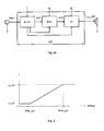
- Fig. 1
- sketches the structure of a simple ICC system aimed to support front-to-rear conversations with one microphone and one loudspeaker;
- Fig. 2
- is an overview of the system;
- Fig. 3a
- shows the sub-band energy decay curve from the test impulse response which may be used for estimating parameters for this sub-band energy decay model;
- Fig. 3b
- shows a block diagram of a circuit for carrying out a preferred embodiment of the method according to the invention;
- Fig. 4a
- illustrates how an echo compensator can be used for decay model parameter estimation; and
- Fig. 4b
- is another block diagram of the ICC-system together with noise dependent gain control (NDGC) and equalizer (Eq).
- In a
room 1, such as a car cabin, there are adriver 2a and apassenger 2b behind. In front of thedriver 2a is amicrophone 3 so that the driver's speech is better intelligible for thepassenger 2b to whom aloudspeaker 4 is assigned. This is a simplified example, because, of course, a (further) microphone might be near thepassenger 2b to be better understood by thedriver 2a to whom a loudspeaker of the type ofloudspeaker 4 may also be assigned. - Clearly, the
microphone 3 will not only take the speech signal s(n) of thedriver 2a, but also the noise b(n), and noise suppression in the line from themicrophone 3 to theloudspeaker 4 is known per se. However, in addition, there are interferences received by the microphone, such as the audio signal fAudio,Mic(n) from afurther loudspeaker 5, by means of which the driver wants, for example, to become informed about street conditions or obtains a navigation aid from an audio-source 6. Thus, the output m(n) of themicrophone 3, which is composed of the voice signal s(n) of thedriver 2a, the noise b(n), the audio-signal fAudio,Mic(n) and the ICC-system feedback signal fICC,Mic(n) coming fromloudspeaker 4, the two latter signals forming interferences. If one feeds at least one of the interferences, such as fAudio,Ls(n), into the ICC-system 7 for suppression, speech of thedriver 2a is better intelligible, because the signal to theloudspeaker 4 is enhanced (vide alsoFig. 2 ). For this invention the signals in time domain with the time index n are defined as lower case characters and signals in sub-band domain with the sub-band index µ and the frame index k are defined as upper case characters. In which for signals played back inside the acoustic room, e.g. vehicle interior, the index Mic is used for the signal at the microphone and the index Ls is used for the signal at the loudspeaker. The index Mic has a different value for each microphone, where it runs for example from 0 to the maximum number ofmicrophones minus 1. The index Ls has a different value for each loudspeaker, where it runs for example from 0 to the maximum number of loudspeakers minus 1 For this invention the upper case character S with an index, i.e. Sbb(µ,k) is used for power signals, while other capital letters, e.g. B(µ,k), are used for complex sub-band signals. The power signal can be approximated as the square of the sub-band signal, e.g. Sbb(µ,k) = |B(µ,k|.2 - Now in detail, the sub-band microphone signal M(µ,k) of a given sub-band µ at a given time k consists of the local speech signal S(µ,k), the background noise B(µ,k), the feedback of the ICC-system output FICC,Mic(µ,k) and the feedback of the audio system FAudio,Mic(µ,k), in which µ is the sub-band index and k is the time frame index. The invention provides a method of interference suppression using a mathematical model on the base of sound energy decay inside a room. In addition to the energy decay there is also a delay effect.
- The signal processing system is estimating an interference signal by an energy decay model with frequency dependent coupling factors, frequency dependent decay factors and frequency dependent delay factors, wherein an estimated interference signal includes at least one product of the respective coupling factor times a respective part of a loudspeaker signal delayed by the respective delay factor plus at least one product of an estimated interference signal at an earlier moment times the respective decay factor, and that the estimated interference signal is used for generating an interference suppressed loudspeaker signal. Frequency dependent coupling factors, frequency dependent decay factors and frequency dependent delay factors can be calculated preferably from a room impulse response.
- The estimated interference signal is a system feedback signal, which can be calculated according to the formula

wherein Sff,Mic,(µ,k) is the estimated feedback level at the microphone Mic, for a predetermined frequency sub-band µ at time k; PLs,Mic(µ) is the coupling factor of the sub-band µ between the loudspeaker Ls and the microphone Mic; Sff,Ls(µ,k-D(µ)) is the feedback signal level at the loudspeaker Ls for a predetermined frequency sub-band at time k-D(µ), D(µ) is the delay factor of the sub-band µ, Sff,Mic,(µ,k-1) is the feedback signal level at the microphone Mic for a predetermined frequency sub-band at time k-1 and e-ϕ(µ) is an exponential decay factor of the sub-band µ. - The interference model parameters are deduced form at least one microphone signal or from automatically detecting and interpreting decaying signal slopes, wherein after deducting the parameters to be applied are updated and the parameter deduction occurs preferably when there is no speech, no audio signal or no ICC-system output.
- The coefficients of an echo compensator can be used for the adaption of the interference model parameters preferably by placing an echo compensator parallel to the signal processing path, wherein the coefficients of the echo compensator are corresponding to the room impulse response and the parameters of the echo compensator should only be updated when there is no local speech detected, e.g. only at the decaying slopes of the microphone signal or only at the feedback of the audio signal.
- By preparing at least two different interference models on the basis of different parameters for different occupancy or different environment conditions and by detecting the actual occupancy of the vehicle or environment condition it is possible to select the interference model in accordance with the actual occupancy or environment condition detected.
- Noise components, as is known, can be suppressed by a Wiener-filter in sub-band domain. Signal processing can be applied in sub-band or also in a melband domain to take the psychoacoustics into the account or to reduce the algorithmic complexity. The difficulty is the estimation of the ICC-system feedback and the audio signal feedback at the microphone. However, the ICC-system feedback and the audio signal feedback are known at the loudspeaker or can be supplied as a reference channel from the output of the ICC and the audio system (
Fig. 2 ). The ICC-system feedback and the audio signal feedback at themicrophone 3 can be calculated now as a convolution of the feedback signal at theloudspeaker 4 and the room impulse response between theloudspeaker 4 and the microphone hLsMic(n):
and
- Because it is very difficult to update or estimate the loudspeaker-microphone impulse response during operating time the method according to the invention uses a model for the energy decay of the room impulse response. The energy decay of the room impulse response is modelled as the outcome of a non-stationary random process.


- In which the energy decay is modeled as

with the reverberation time T60, the sampling frequency fs. and the scaling factor for the signal energy σ2. - Similar to the time domain description, a constant decay of the energy in the sub-band domain is assumed as


- In which PLsMic(µ) is the coupling factor of the sub-band µ between the loudspeaker and the microphone and the energy decay ϕ(µ) is modelled as

with the sub-band reverberation time T60(µ), the sampling frequency fs, the frame shift N, the frame index k and the delay parameter D(µ). - The parameters for this sub-band energy decay model GLsMic(µ,k) can be estimated from the sub-band energy decay curve from the impulse response as shown in
Fig. 3a . Dependent on the use case, there are maybe different loudspeakers used for playing back the audio and the ICC system output. Therefore different model parameters from different impulse responses are used for ICC-system and audio system feedback suppression. - Very similar energy decay models can be used e.g. for dereverberation of a microphone signal. This has been disclosed in
US2009/0117948 and also by E. Habets in "Multichannel speech dereverberation based on a statistical model of late reverberation," in ICASSP, 2005. In the case of the present invention, the model is used for estimation of the ICC-system output and the audio signal at the microphone, i.e. for interference estimation. In the sub-band domain the estimation of the feedback signal at theloudspeaker 4 can be estimated with the recursive notation:

- Where Sff,ICC,Mic(µ,k) is the estimated feedback of the ICC-system output at the microphone and Sff,Audio,Mic(µ,k) is the estimated feedback of the audio signal at the microphone. It should be noted that the sign S with an index, i.e. Sxx(µ,k) is used in this specification for power, while other capital letters, such as M(µ,k) or B(µ,k), are used for complex sub-band signals. The power signal can be approximated as the square of the sub-band signal, e.g. Sbb(µ,k) = |B(µ,k|2.
- After the estimation of the interfering signals these components can be suppressed. Therefore Spectral Subtraction, e.g. Wiener-filter in the sub-band domain can be used. Here the attenuation of the filter coefficients is constrained to a maximum attenuation (spectral floor) β(µ).

- For reduction of the artefacts caused by the interference suppression, also called musical noise, an overestimation factor γ(µ) will be used. Conventionally the overestimation factor γ(µ) is a fixed value, with e.g. 1 ≤ γ(µ) 3. Because these artefacts are masked by the residual noise primarily caused by the noise suppression the improved solution contains a SNR(k,µ) (signal to noise ration) dependent overestimation factor γ(k, µ). Where the SNR(k,µ) is defined as

- Where T(µ,k) is the feedback and noise suppressed signal and approximates the clean local speech signal Sss(µ,k) power and Sbb(µ,k) is the estimated nose signal power.
- This adaptation of the SNR(k,µ) dependent overestimation factor γ(k,µ) depends on a characteristic which maps the SNR(k,µ) to the overestimation factor γ(k,µ). Some sample characteristics are depicted in
Fig. 5 . Common parameters are γmin(µ) = 1; γmax(µ) =3; SNRmin(µ) = 5 dB; SNRmax(µ) = 15 dB.


- The overestimation factor γ(k,µ) can also be defined and determined for every processing step as γF,ICC(k,µ), γF,Adio(k,µ) and γB(k,µ).
- It is beneficial to suppress the feedback and the audio signal before estimating the noise power and suppress the background noise. Due to the assumption that the power of the single signal components is uncorrelated, the power of the microphone signal can be defined as:

- Where all components are known or can be estimated as shown before, beside the power of the clean speech signal Sss(µ,k) which is unknown.
- In the illustrated embodiment, it is started with the ICC-system feedback suppression, but other arrangements are also possible. The coefficients of the feedback suppression filter can be calculated, e.g.

- This filter can be applied to the disturbed microphone signal.

to obtain the ICC-system feedback suppressed signal R(µ,k). - Now this ICC-system feedback suppressed signal R(µ,k) can advantageously be used for suppressing the audio system feedback.

- This filter can be applied to the processed microphone signal R(µ,k)

to obtain the ICC-system and audio system feedback suppressed signal L(µ,k). - Now the ICC-system and audio system feedback suppressed signal L(µ,k) can be used for noise signal suppression. The power of the background noise Sbb(µ,k) is a stationary process and can be estimated from noisy speech signal, e.g. in speech pauses as:


- With the estimated noise power the filter coefficients of the noise suppression filter can be calculated as:

- This filter can be applied to the noisy already ICC-system and audio system feedback suppressed signal L(µ,k)

to obtain the feedback and noise suppressed signal T(µ,k). - The suppression of these interferences has an influence to the signal output level of the processed speech and the residual interferences. Therefore the signal output level needs to be adjusted due to the signal suppression to keep the long term output and residual interference level constant. This amplification factor can be calculated for every sub-band V(µ,k) or as scalar fullband parameter v(k). One possible implementation for the update of the amplification factor is to calculate the update terms for every filter.

- Where the mean value of the filter coefficients is used for the update of the with smoothing parameter α smoothed amplification correction factor. Therefore 0≤α≤0.1 and Nsub is the number of the sub-bands. The parameter VAudio(k) and VB(k) are calculated the same way.
- Now the gain correction factors are combined to get the final gain correction factor

- The calculated amplification factor can be applied to the processed signal to correct the long term power level difference caused by the signal processing

- Where γ(µ,k) is the output of the signal enhancement.
- Certainly the amplification of the output signal changes the level of the residual interferences of the processed signal. To correct the power level of the residual interference signal the amplification factor can be used for adjusting the spectral floor of the filter calculation:

- Where βstart(µ) is the initial value for the spectral floor. The parameter βAudio(µ,k) and βB(µ,k) are updated the same way.
- The described method enables to enhance the interfered signal by a very robust and efficient way with a circuit schematically shown in
Fig. 3b . The configuration shown inFig. 3b depends on the actual system setup. Feedback suppression, audio suppression and noise suppression is applied stepwise, where for all these suppression steps corresponding estimations of interference signals are used. InFig. 3b the suppression modules are arranged in the following order: Feedback, Audio and Noise. Rearrangements of the used modules are possible and may in some cases be necessary. It is possible to perform every processing step independently like shown before. There the modules can also be rearranged and/or combined. - Combination and application of the filter coefficients of different modules can be described as follows

- Where H(µ,k) is the combined interference suppression filter coefficients dependent on the single components ICC-system feedback suppression filter coefficients HF,ICC(µ,k), audio system feedback suppression filter coefficients HF,Audio(µ,k) and noise suppression filter coefficients HB(µ,k).
- In that case the enhanced signal can be calculated now as

- According to
Fig. 3b , the microphone signal M(µ,k) is transformed by a ICC-systemfeedback suppression step 11 to a feedback reduced signal R(µ,k). In order to ensure that the suppression in thisstep 11 works precisely, there is an ICC-systemfeedback estimation step 12 preposed. In thestep 12 the ICC-system feedback signal at the loudspeaker FICC,Ls(µ,k) and determines the interference signal level Sff,ICC,Mic(µ,k) by applying the room energy decay model parameters on the base of the sub-band coupling factor PLsMic(µ) times the magnitude square of a sub-band delayed loudspeaker signal FICC,Ls(µ,k-D(µ)) plus a last interference signal level Sff,ICC,Mic(µ,k-1) times a sub-band decay factor e-ϕ(µ). The output ofmodule 12, the estimated interference signal level Sff,ICC,Mic(µ,k), is delivered tomodule 11 and is used there to suppress the interference signal accordingly. - The same applies to the feedback of the audio system and feeding the estimated signal level Sff,Audio,Mic(µ,k) of the
stage 13 to an audio systemfeedback suppression stage 14. - The output of
module 14 is now freed from feedback interference components and can, therefore, better be used for noise estimation inmodule 15, to feed anoise suppression stage 16. Since the enhanced signal has lost power, it is useful, to correct the signal level by again control module 17 which forms a power level corrected signal γ(µ,k) and is in connection withmodules gain control stage 17 analyzes the filter coefficients of themodules modules - In general, from the three energy decay model parameter, the delay D(µ) and the energy decay e-ϕ(µ) are related to the used hardware and the room characteristics e.g. the reverberation time T60. The changes of these parameters are slow and small. The coupling factor PLsMic(µ) depends on the actual position of the passengers inside the car and is changing faster. In the majority of cases it is sufficient only to adapt this parameter during signal processing.
- As described before the room energy decay parameters can be estimated from the impulse response respectively the sub-band impulse response. This impulse response can be measured, before calculating the signal processing and the estimated model parameters D(µ), PLsMic(µ) and e-ϕ(µ), see also
Fig 3a . With these parameters, signal processing can be applied. - Due to the changes of the impulse response, caused by changes of the car occupancy and environment conditions, e.g. open window or door, it is suitable to repeat the impulse response measurements for different car occupancies and environment conditions, e.g. to have different decay models for different occupancies and environment conditions. The occupancy or environment conditions of the car can be detected, e.g. with seat sensors or window sensor, and the signal processing can switch to the actual predefined decay model.
- Another possibility to estimate the room energy decay model parameters, is the use of an echo compensator 18 (
Fig. 4a ) which is placed parallel to thesignal processing path 7. The output of theecho compensator 18 is not used for feedback compensation, but only for updating the echo compensator. Due to the correspondence of the coefficients of the echo compensator to the room impulse response (as is known fromEP-A-2151983 ), the estimated coefficients can be used in a very similar way to estimate or to update the decay model parameter during the signal processing. The parameters of the echo compensator should only be updated when there is no local speech detected, e.g. only at the decaying slopes of the microphone signal or only at the feedback of the audio signal. - A further possibility to estimate the room energy decay model parameters, is to use of frequency/phase shift methods or other decorrelation methods like nonlinearities at the system output or additional noise signal. The decay model parameter can be easily updated from this decorrelated loudspeaker signal. This method can be used together to the
parallel echo compensator 18 to support and accelerate the adaptation of theecho compensator 18. - Still another possibility to estimate the room energy decay model parameters, is to automatically detect and interpret the decaying signal slopes. In this case, the energy decay of the slope needs to be monitored. The fastest decay appears when there is no additional excitation signal, e.g. no local speech, no audio signal or no ICC-system output. After detecting these moments the room energy decay model parameters can be updated by the estimated sub-band decay and the sub-band transfer at the beginning of the slope.
- Another possibility is to update the decay model parameter from the calculated cross correlation between the loudspeaker signal FICC,Ls(µ,k) and the microphone signal M(µ,k) to estimate the room energy decay model parameters.
- The described model for the energy decay can also be used for adjusting the coefficients of the equalizer which can also be a part of the ICC system. Therefore the sub-band coupling parameter PLsMic(µ,k) can be used to set up the sub-band equalizer 19 (vide
Fig 4b ) to improve the stability ICC-system gain in term of maximum ICC-system gain, due to the correlation between the room impulse response hLsMic(n) and the sub-band coupling parameter PLsMic(µ,k). The sub-band attenuation of the equalizer HEq(µ,k) can be determined directly from the sub-band coupling parameter PLsMic(µ,k)
- The estimation of the interference components can also be used to set up the ICC system gain. Of course, this gain is dependent on the background noise level Sbb(µ,k). But it is also dependent on the level of the feedback and audio signal. Because for a high feedback the ICC system produces many artefacts the system gain should be reduced. For very high audio signal level, the passengers prefer to listen to the audio system. The audio level at the microphone Sff,Audio,Mic(µ,k) can be estimated with the described method. This signal correlates to the sound level inside the car. In relation to the ratio between the estimated audio signal and the processed signal the system gain can be reduced or the system can be deactivated in order to not disturb the passengers, while listening music. For very high ICC-system feedback level Sff,ICC,Mic(µ,k) at the microphone the processed signal contains many artefacts caused by the signal processing. For reduction of this artefacts the ICC-system gain should be reduced to reduce the level of the feedback signal Sff,ICC,Mic(µ,k) or switch off the ICC-system while the ICC-system is working under inconvenient or not acceptable conditions.
- The communication system gain can be adjusted according to the estimated interference signal level, wherein this gain is dependent on the background noise level and on the level of the communication system feedback and audio system signal, for a high communication system feedback or for a high audio signal level the system gain should be reduced.
Claims (15)
- Method for interference suppression for an communication system as an indoor communication system or a handsfree telephony system or an automatic speech recognition system, comprising at least one loudspeaker, at least one microphone and a signal processing system, particularly in a vehicle, wherein the microphone is recording a signal comprising communication information and interferences, the signal processing system is processing the microphone signal and providing a loudspeaker signal and the loudspeaker is emitting a sound signal corresponding to the loudspeaker signal, characterized in that the signal processing system is estimating an interference signal by an energy decay model with frequency dependent coupling factors, frequency dependent decay factors and frequency dependent delay factors, wherein an estimated interference signal includes at least one product of the respective coupling factor times a respective part of a loudspeaker signal delayed by the respective delay factor plus at least one product of an estimated interference signal at an earlier moment times the respective decay factor, and that the estimated interference signal is used for generating an interference suppressed loudspeaker signal.
- Method according to claim 1, characterized in that the estimated interference signal is calculated according to the formula

wherein Sff,Mic(µ,k) is the estimated interference signal level at the microphone Mic, for a predetermined frequency sub-band µ at time k; PLsMic(µ) is the coupling factor of the sub-band µ between the loudspeaker Ls and the microphone Mic; Sff,Ls(µ,k-D(µ)) is the interference signal level at the loudspeaker Ls for a predetermined frequency sub-band at time k-D(µ), D(µ) is the delay factor of the sub-band µ, Sff,Mic(µ,k-1) is the interference signal level at the microphone Mic for a predetermined frequency sub-band at time k-1 and e-ϕ(µ) is an exponential decay factor of the sub-band µ. - Method according to claim 1 or 2, characterized in that the estimated interference signal is a communication system feedback signal or an audio-system feedback, wherein the audio signal is a part or all of the loudspeaker signal at loudspeaker Ls.
- Method according to claim 1, wherein a test signal is sent to the respective loudspeaker for determining system characteristics on the base of the test signal received by the respective microphone, wherein the system characteristics detected by the application of the test signal are used to determine the frequency dependent coupling factors, the frequency dependent decay factors and frequency dependent delay factors.
- Method according to any of the preceding claims, characterized in that generating an interference suppressed loudspeaker signal is performed by Spectral Subtraction, preferably by the application of a Wiener-filter using the estimated interference signal.
- Method according to any of the preceding claims, characterized in that an overestimation γ(µ,k) of the estimated interference signal of the sub-band µ is adjusted to an estimated noise to speech signal ratio SNR(µ,k) of the sub-band µ deduced by a noise suppression module and that a maximum attenuation β(µ,k) of the sub-band µ is adjusted to a gain correction factor V(µ,k) of the sub-band µ.
- Method according to any of the preceding claims, further characterized by applying stepwise independently or combined at least two suppressing steps out of communication system feedback suppression, audio system feedback suppression and noise suppression, wherein for all the suppression steps corresponding estimations of interference signals are used, and the suppression modules can be arranged in any order, but are preferably arranged in the following order: communication system feedback, audio system feedback and noise.
- Method according to any of the preceding claims, characterized in that the interference model parameters are deduced from at least one microphone signal or by automatically detecting and interpreting decaying signal slopes, wherein after deducting the parameters to be applied are updated and the parameter deduction occurs preferably when there is no local speech.
- Method according to any of the preceding claims, characterized by the further steps of preparing at least two different interference models on the basis of different parameters for different occupancy or different environment conditions; detecting the actual occupancy of the vehicle or environment condition; and selecting the interference models in accordance with the actual occupancy or environment condition detected.
- Method according to any of the preceding claims, characterized in that the coefficients of an echo compensator are used for the adaption of the interference model parameters preferably by placing an echo compensator parallel to the signal processing path, wherein the coefficients of the echo compensator are corresponding to the room impulse response and the parameters of the echo compensator should only be updated when there is no local speech detected, e.g. only at the decaying slopes of the microphone signal or only at the feedback of the audio signal.
- Method, characterized by adjusting a communication system equalizer HEq(µ,k) according to the energy decay model frequency dependent coupling factors PLsMic(µ,k).
- Method, characterized by adjusting the communication system gain according to the estimated interference signal level, wherein this gain is dependent on the background noise level and on the level of the communication system feedback and audio system feedback, for a high communication system feedback or audio system feedback signal level the system gain should be reduced.
- Software product for determining interference model parameters in the form of frequency dependent coupling factors and frequency dependent decay values that an estimated interference signal is formed on the base of the coupling factor times a loudspeaker signal plus a microphone signal at an earlier moment times a decay factor depending on the decay value.
- Software product for carrying out the method according to any of the preceding claims.
- Communication system as an indoor communication system or handsfree telephony system or automatic speech recognition system, comprising at least one loudspeaker and at least one microphone, as well as a signal treatment device, which carries out a method according to any of claims 1 to 12.
Priority Applications (1)
| Application Number | Priority Date | Filing Date | Title |
|---|---|---|---|
| EP11155047.1A EP2490218B1 (en) | 2011-02-18 | 2011-02-18 | Method for interference suppression |
Applications Claiming Priority (1)
| Application Number | Priority Date | Filing Date | Title |
|---|---|---|---|
| EP11155047.1A EP2490218B1 (en) | 2011-02-18 | 2011-02-18 | Method for interference suppression |
Publications (2)
| Publication Number | Publication Date |
|---|---|
| EP2490218A1 true EP2490218A1 (en) | 2012-08-22 |
| EP2490218B1 EP2490218B1 (en) | 2019-09-25 |
Family
ID=44351427
Family Applications (1)
| Application Number | Title | Priority Date | Filing Date |
|---|---|---|---|
| EP11155047.1A Active EP2490218B1 (en) | 2011-02-18 | 2011-02-18 | Method for interference suppression |
Country Status (1)
| Country | Link |
|---|---|
| EP (1) | EP2490218B1 (en) |
Cited By (5)
| Publication number | Priority date | Publication date | Assignee | Title |
|---|---|---|---|---|
| CN104601258A (en) * | 2014-12-23 | 2015-05-06 | 中国北方车辆研究所 | Multi-machine mutual-interference test method for vehicle-mounted communication systems in the same car |
| WO2017000813A1 (en) * | 2015-06-30 | 2017-01-05 | 芋头科技(杭州)有限公司 | Indoor noise pollution automatic identification and monitoring system |
| JP2017146207A (en) * | 2016-02-17 | 2017-08-24 | アルパイン株式会社 | On-vehicle device |
| US10002601B2 (en) | 2015-12-30 | 2018-06-19 | Qualcomm Incorporated | In-vehicle communication signal processing |
| CN112309364A (en) * | 2020-11-04 | 2021-02-02 | 广州市立锐升电子有限公司 | Method, system and chip for realizing DSP multichannel squeal reduction processing |
Citations (5)
| Publication number | Priority date | Publication date | Assignee | Title |
|---|---|---|---|---|
| EP1885154A1 (en) * | 2006-08-01 | 2008-02-06 | Harman Becker Automotive Systems GmbH | Dereverberation of microphone signals |
| WO2008122930A1 (en) * | 2007-04-04 | 2008-10-16 | Koninklijke Philips Electronics N.V. | Sound enhancement in closed spaces |
| US20090117948A1 (en) | 2007-10-31 | 2009-05-07 | Harman Becker Automotive Systems Gmbh | Method for dereverberation of an acoustic signal |
| EP1718103B1 (en) | 2005-04-29 | 2009-12-02 | Harman Becker Automotive Systems GmbH | Compensation of reverberation and feedback |
| EP2151983A1 (en) | 2008-08-07 | 2010-02-10 | Harman Becker Automotive Systems GmbH | Hands-free telephony and in-vehicle communication |
-
2011
- 2011-02-18 EP EP11155047.1A patent/EP2490218B1/en active Active
Patent Citations (5)
| Publication number | Priority date | Publication date | Assignee | Title |
|---|---|---|---|---|
| EP1718103B1 (en) | 2005-04-29 | 2009-12-02 | Harman Becker Automotive Systems GmbH | Compensation of reverberation and feedback |
| EP1885154A1 (en) * | 2006-08-01 | 2008-02-06 | Harman Becker Automotive Systems GmbH | Dereverberation of microphone signals |
| WO2008122930A1 (en) * | 2007-04-04 | 2008-10-16 | Koninklijke Philips Electronics N.V. | Sound enhancement in closed spaces |
| US20090117948A1 (en) | 2007-10-31 | 2009-05-07 | Harman Becker Automotive Systems Gmbh | Method for dereverberation of an acoustic signal |
| EP2151983A1 (en) | 2008-08-07 | 2010-02-10 | Harman Becker Automotive Systems GmbH | Hands-free telephony and in-vehicle communication |
Non-Patent Citations (5)
| Title |
|---|
| E. HABETS: "Multichannel speech dereverberation based on a statistical model of late reverberation", ICASSP, 2005 |
| E. HANSIER; G. SCHMIDT: "Topics in acoustic echo and noise control", 2006, SPRINGER, pages: 549 - 598 |
| E. LLEIDA; E. MASGRAU; A. ORTEGA: "Acoustic echo and noise reduction for car cabin communication", PROC. EUROSPEECH '01, vol. 3, 2001, pages 1585 - 1588 |
| SCHMIDT G ET AL: "Signal processing for in-car communication systems", SIGNAL PROCESSING, ELSEVIER SCIENCE PUBLISHERS B.V. AMSTERDAM, NL, vol. 86, no. 6, 1 June 2006 (2006-06-01), pages 1307 - 1326, XP024997680, ISSN: 0165-1684, [retrieved on 20060601], DOI: 10.1016/J.SIGPRO.2005.07.040 * |
| T. HAULICK; G. SCHMIDT: "Signal processing for in-car communication systems", SIGNAL PROCESSING, June 2006 (2006-06-01), pages 1307 - 1326, XP024997680, DOI: doi:10.1016/j.sigpro.2005.07.040 |
Cited By (5)
| Publication number | Priority date | Publication date | Assignee | Title |
|---|---|---|---|---|
| CN104601258A (en) * | 2014-12-23 | 2015-05-06 | 中国北方车辆研究所 | Multi-machine mutual-interference test method for vehicle-mounted communication systems in the same car |
| WO2017000813A1 (en) * | 2015-06-30 | 2017-01-05 | 芋头科技(杭州)有限公司 | Indoor noise pollution automatic identification and monitoring system |
| US10002601B2 (en) | 2015-12-30 | 2018-06-19 | Qualcomm Incorporated | In-vehicle communication signal processing |
| JP2017146207A (en) * | 2016-02-17 | 2017-08-24 | アルパイン株式会社 | On-vehicle device |
| CN112309364A (en) * | 2020-11-04 | 2021-02-02 | 广州市立锐升电子有限公司 | Method, system and chip for realizing DSP multichannel squeal reduction processing |
Also Published As
| Publication number | Publication date |
|---|---|
| EP2490218B1 (en) | 2019-09-25 |
Similar Documents
| Publication | Publication Date | Title |
|---|---|---|
| EP2237271B1 (en) | Method for determining a signal component for reducing noise in an input signal | |
| US9414158B2 (en) | Single-channel, binaural and multi-channel dereverberation | |
| US9992572B2 (en) | Dereverberation system for use in a signal processing apparatus | |
| EP1855456B1 (en) | Echo reduction in time-variant systems | |
| KR100860805B1 (en) | Voice enhancement system | |
| JP4755506B2 (en) | Audio enhancement system and method | |
| EP1591995B1 (en) | Indoor communication system for a vehicular cabin | |
| EP1718103B1 (en) | Compensation of reverberation and feedback | |
| US10553236B1 (en) | Multichannel noise cancellation using frequency domain spectrum masking | |
| Schmidt et al. | Signal processing for in-car communication systems | |
| JP4689269B2 (en) | Static spectral power dependent sound enhancement system | |
| US10755728B1 (en) | Multichannel noise cancellation using frequency domain spectrum masking | |
| EP3441969B1 (en) | Synthetic speech for in vehicle communication | |
| WO2009148049A1 (en) | Acoustic echo canceller and acoustic echo cancel method | |
| EP2597639A2 (en) | Sound processing device | |
| EP3025516B1 (en) | Automatic timbre, loudness and equalization control | |
| TWI666631B (en) | Comfort noise generation apparatus and method | |
| EP2490218B1 (en) | Method for interference suppression | |
| US8199928B2 (en) | System for processing an acoustic input signal to provide an output signal with reduced noise | |
| EP3529805B1 (en) | Apparatus and method for processing an audio signal | |
| EP3830823B1 (en) | Forced gap insertion for pervasive listening | |
| Miyazaki et al. | Theoretical analysis of parametric blind spatial subtraction array and its application to speech recognition performance prediction | |
| RU2589298C1 (en) | Method of increasing legible and informative audio signals in the noise situation | |
| Gimm et al. | Energy-Decay Based Postfilter for ICC Systems with Feedback Cancellation | |
| Mosayyebpour et al. | Single-microphone speech enhancement by skewness maximization and spectral subtraction |
Legal Events
| Date | Code | Title | Description |
|---|---|---|---|
| PUAI | Public reference made under article 153(3) epc to a published international application that has entered the european phase |
Free format text: ORIGINAL CODE: 0009012 |
|
| AK | Designated contracting states |
Kind code of ref document: A1 Designated state(s): AL AT BE BG CH CY CZ DE DK EE ES FI FR GB GR HR HU IE IS IT LI LT LU LV MC MK MT NL NO PL PT RO RS SE SI SK SM TR |
|
| AX | Request for extension of the european patent |
Extension state: BA ME |
|
| 17P | Request for examination filed |
Effective date: 20130213 |
|
| STAA | Information on the status of an ep patent application or granted ep patent |
Free format text: STATUS: EXAMINATION IS IN PROGRESS |
|
| 17Q | First examination report despatched |
Effective date: 20180413 |
|
| REG | Reference to a national code |
Ref country code: DE Ref legal event code: R079 Ref document number: 602011062262 Country of ref document: DE Free format text: PREVIOUS MAIN CLASS: G10L0021020000 Ipc: G10L0021020800 |
|
| GRAP | Despatch of communication of intention to grant a patent |
Free format text: ORIGINAL CODE: EPIDOSNIGR1 |
|
| STAA | Information on the status of an ep patent application or granted ep patent |
Free format text: STATUS: GRANT OF PATENT IS INTENDED |
|
| RIC1 | Information provided on ipc code assigned before grant |
Ipc: G10L 21/0208 20130101AFI20181129BHEP |
|
| INTG | Intention to grant announced |
Effective date: 20181214 |
|
| RIC1 | Information provided on ipc code assigned before grant |
Ipc: G10L 21/0208 20130101AFI20181129BHEP |
|
| GRAJ | Information related to disapproval of communication of intention to grant by the applicant or resumption of examination proceedings by the epo deleted |
Free format text: ORIGINAL CODE: EPIDOSDIGR1 |
|
| STAA | Information on the status of an ep patent application or granted ep patent |
Free format text: STATUS: EXAMINATION IS IN PROGRESS |
|
| GRAP | Despatch of communication of intention to grant a patent |
Free format text: ORIGINAL CODE: EPIDOSNIGR1 |
|
| STAA | Information on the status of an ep patent application or granted ep patent |
Free format text: STATUS: GRANT OF PATENT IS INTENDED |
|
| INTC | Intention to grant announced (deleted) | ||
| INTG | Intention to grant announced |
Effective date: 20190514 |
|
| GRAS | Grant fee paid |
Free format text: ORIGINAL CODE: EPIDOSNIGR3 |
|
| GRAA | (expected) grant |
Free format text: ORIGINAL CODE: 0009210 |
|
| STAA | Information on the status of an ep patent application or granted ep patent |
Free format text: STATUS: THE PATENT HAS BEEN GRANTED |
|
| AK | Designated contracting states |
Kind code of ref document: B1 Designated state(s): AL AT BE BG CH CY CZ DE DK EE ES FI FR GB GR HR HU IE IS IT LI LT LU LV MC MK MT NL NO PL PT RO RS SE SI SK SM TR |
|
| REG | Reference to a national code |
Ref country code: GB Ref legal event code: FG4D |
|
| REG | Reference to a national code |
Ref country code: CH Ref legal event code: EP |
|
| REG | Reference to a national code |
Ref country code: DE Ref legal event code: R096 Ref document number: 602011062262 Country of ref document: DE |
|
| REG | Reference to a national code |
Ref country code: AT Ref legal event code: REF Ref document number: 1184613 Country of ref document: AT Kind code of ref document: T Effective date: 20191015 |
|
| REG | Reference to a national code |
Ref country code: IE Ref legal event code: FG4D |
|
| REG | Reference to a national code |
Ref country code: NL Ref legal event code: FP |
|
| PG25 | Lapsed in a contracting state [announced via postgrant information from national office to epo] |
Ref country code: FI Free format text: LAPSE BECAUSE OF FAILURE TO SUBMIT A TRANSLATION OF THE DESCRIPTION OR TO PAY THE FEE WITHIN THE PRESCRIBED TIME-LIMIT Effective date: 20190925 Ref country code: HR Free format text: LAPSE BECAUSE OF FAILURE TO SUBMIT A TRANSLATION OF THE DESCRIPTION OR TO PAY THE FEE WITHIN THE PRESCRIBED TIME-LIMIT Effective date: 20190925 Ref country code: LT Free format text: LAPSE BECAUSE OF FAILURE TO SUBMIT A TRANSLATION OF THE DESCRIPTION OR TO PAY THE FEE WITHIN THE PRESCRIBED TIME-LIMIT Effective date: 20190925 Ref country code: BG Free format text: LAPSE BECAUSE OF FAILURE TO SUBMIT A TRANSLATION OF THE DESCRIPTION OR TO PAY THE FEE WITHIN THE PRESCRIBED TIME-LIMIT Effective date: 20191225 Ref country code: SE Free format text: LAPSE BECAUSE OF FAILURE TO SUBMIT A TRANSLATION OF THE DESCRIPTION OR TO PAY THE FEE WITHIN THE PRESCRIBED TIME-LIMIT Effective date: 20190925 Ref country code: NO Free format text: LAPSE BECAUSE OF FAILURE TO SUBMIT A TRANSLATION OF THE DESCRIPTION OR TO PAY THE FEE WITHIN THE PRESCRIBED TIME-LIMIT Effective date: 20191225 |
|
| REG | Reference to a national code |
Ref country code: LT Ref legal event code: MG4D |
|
| PG25 | Lapsed in a contracting state [announced via postgrant information from national office to epo] |
Ref country code: LV Free format text: LAPSE BECAUSE OF FAILURE TO SUBMIT A TRANSLATION OF THE DESCRIPTION OR TO PAY THE FEE WITHIN THE PRESCRIBED TIME-LIMIT Effective date: 20190925 Ref country code: RS Free format text: LAPSE BECAUSE OF FAILURE TO SUBMIT A TRANSLATION OF THE DESCRIPTION OR TO PAY THE FEE WITHIN THE PRESCRIBED TIME-LIMIT Effective date: 20190925 Ref country code: GR Free format text: LAPSE BECAUSE OF FAILURE TO SUBMIT A TRANSLATION OF THE DESCRIPTION OR TO PAY THE FEE WITHIN THE PRESCRIBED TIME-LIMIT Effective date: 20191226 |
|
| REG | Reference to a national code |
Ref country code: AT Ref legal event code: MK05 Ref document number: 1184613 Country of ref document: AT Kind code of ref document: T Effective date: 20190925 |
|
| PG25 | Lapsed in a contracting state [announced via postgrant information from national office to epo] |
Ref country code: EE Free format text: LAPSE BECAUSE OF FAILURE TO SUBMIT A TRANSLATION OF THE DESCRIPTION OR TO PAY THE FEE WITHIN THE PRESCRIBED TIME-LIMIT Effective date: 20190925 Ref country code: PL Free format text: LAPSE BECAUSE OF FAILURE TO SUBMIT A TRANSLATION OF THE DESCRIPTION OR TO PAY THE FEE WITHIN THE PRESCRIBED TIME-LIMIT Effective date: 20190925 Ref country code: AT Free format text: LAPSE BECAUSE OF FAILURE TO SUBMIT A TRANSLATION OF THE DESCRIPTION OR TO PAY THE FEE WITHIN THE PRESCRIBED TIME-LIMIT Effective date: 20190925 Ref country code: ES Free format text: LAPSE BECAUSE OF FAILURE TO SUBMIT A TRANSLATION OF THE DESCRIPTION OR TO PAY THE FEE WITHIN THE PRESCRIBED TIME-LIMIT Effective date: 20190925 Ref country code: RO Free format text: LAPSE BECAUSE OF FAILURE TO SUBMIT A TRANSLATION OF THE DESCRIPTION OR TO PAY THE FEE WITHIN THE PRESCRIBED TIME-LIMIT Effective date: 20190925 Ref country code: PT Free format text: LAPSE BECAUSE OF FAILURE TO SUBMIT A TRANSLATION OF THE DESCRIPTION OR TO PAY THE FEE WITHIN THE PRESCRIBED TIME-LIMIT Effective date: 20200127 Ref country code: IT Free format text: LAPSE BECAUSE OF FAILURE TO SUBMIT A TRANSLATION OF THE DESCRIPTION OR TO PAY THE FEE WITHIN THE PRESCRIBED TIME-LIMIT Effective date: 20190925 Ref country code: AL Free format text: LAPSE BECAUSE OF FAILURE TO SUBMIT A TRANSLATION OF THE DESCRIPTION OR TO PAY THE FEE WITHIN THE PRESCRIBED TIME-LIMIT Effective date: 20190925 |
|
| PG25 | Lapsed in a contracting state [announced via postgrant information from national office to epo] |
Ref country code: SK Free format text: LAPSE BECAUSE OF FAILURE TO SUBMIT A TRANSLATION OF THE DESCRIPTION OR TO PAY THE FEE WITHIN THE PRESCRIBED TIME-LIMIT Effective date: 20190925 Ref country code: SM Free format text: LAPSE BECAUSE OF FAILURE TO SUBMIT A TRANSLATION OF THE DESCRIPTION OR TO PAY THE FEE WITHIN THE PRESCRIBED TIME-LIMIT Effective date: 20190925 Ref country code: IS Free format text: LAPSE BECAUSE OF FAILURE TO SUBMIT A TRANSLATION OF THE DESCRIPTION OR TO PAY THE FEE WITHIN THE PRESCRIBED TIME-LIMIT Effective date: 20200224 Ref country code: CZ Free format text: LAPSE BECAUSE OF FAILURE TO SUBMIT A TRANSLATION OF THE DESCRIPTION OR TO PAY THE FEE WITHIN THE PRESCRIBED TIME-LIMIT Effective date: 20190925 |
|
| REG | Reference to a national code |
Ref country code: DE Ref legal event code: R097 Ref document number: 602011062262 Country of ref document: DE |
|
| PG2D | Information on lapse in contracting state deleted |
Ref country code: IS |
|
| PG25 | Lapsed in a contracting state [announced via postgrant information from national office to epo] |
Ref country code: DK Free format text: LAPSE BECAUSE OF FAILURE TO SUBMIT A TRANSLATION OF THE DESCRIPTION OR TO PAY THE FEE WITHIN THE PRESCRIBED TIME-LIMIT Effective date: 20190925 Ref country code: IS Free format text: LAPSE BECAUSE OF FAILURE TO SUBMIT A TRANSLATION OF THE DESCRIPTION OR TO PAY THE FEE WITHIN THE PRESCRIBED TIME-LIMIT Effective date: 20200126 |
|
| PLBE | No opposition filed within time limit |
Free format text: ORIGINAL CODE: 0009261 |
|
| STAA | Information on the status of an ep patent application or granted ep patent |
Free format text: STATUS: NO OPPOSITION FILED WITHIN TIME LIMIT |
|
| 26N | No opposition filed |
Effective date: 20200626 |
|
| REG | Reference to a national code |
Ref country code: CH Ref legal event code: PL |
|
| GBPC | Gb: european patent ceased through non-payment of renewal fee |
Effective date: 20200218 |
|
| REG | Reference to a national code |
Ref country code: BE Ref legal event code: MM Effective date: 20200229 |
|
| PG25 | Lapsed in a contracting state [announced via postgrant information from national office to epo] |
Ref country code: LU Free format text: LAPSE BECAUSE OF NON-PAYMENT OF DUE FEES Effective date: 20200218 Ref country code: MC Free format text: LAPSE BECAUSE OF FAILURE TO SUBMIT A TRANSLATION OF THE DESCRIPTION OR TO PAY THE FEE WITHIN THE PRESCRIBED TIME-LIMIT Effective date: 20190925 |
|
| PG25 | Lapsed in a contracting state [announced via postgrant information from national office to epo] |
Ref country code: CH Free format text: LAPSE BECAUSE OF NON-PAYMENT OF DUE FEES Effective date: 20200229 Ref country code: SI Free format text: LAPSE BECAUSE OF FAILURE TO SUBMIT A TRANSLATION OF THE DESCRIPTION OR TO PAY THE FEE WITHIN THE PRESCRIBED TIME-LIMIT Effective date: 20190925 Ref country code: LI Free format text: LAPSE BECAUSE OF NON-PAYMENT OF DUE FEES Effective date: 20200229 |
|
| PG25 | Lapsed in a contracting state [announced via postgrant information from national office to epo] |
Ref country code: IE Free format text: LAPSE BECAUSE OF NON-PAYMENT OF DUE FEES Effective date: 20200218 Ref country code: GB Free format text: LAPSE BECAUSE OF NON-PAYMENT OF DUE FEES Effective date: 20200218 Ref country code: FR Free format text: LAPSE BECAUSE OF NON-PAYMENT OF DUE FEES Effective date: 20200229 |
|
| PG25 | Lapsed in a contracting state [announced via postgrant information from national office to epo] |
Ref country code: BE Free format text: LAPSE BECAUSE OF NON-PAYMENT OF DUE FEES Effective date: 20200229 |
|
| REG | Reference to a national code |
Ref country code: GB Ref legal event code: 732E Free format text: REGISTERED BETWEEN 20220113 AND 20220119 |
|
| PG25 | Lapsed in a contracting state [announced via postgrant information from national office to epo] |
Ref country code: TR Free format text: LAPSE BECAUSE OF FAILURE TO SUBMIT A TRANSLATION OF THE DESCRIPTION OR TO PAY THE FEE WITHIN THE PRESCRIBED TIME-LIMIT Effective date: 20190925 Ref country code: MT Free format text: LAPSE BECAUSE OF FAILURE TO SUBMIT A TRANSLATION OF THE DESCRIPTION OR TO PAY THE FEE WITHIN THE PRESCRIBED TIME-LIMIT Effective date: 20190925 Ref country code: CY Free format text: LAPSE BECAUSE OF FAILURE TO SUBMIT A TRANSLATION OF THE DESCRIPTION OR TO PAY THE FEE WITHIN THE PRESCRIBED TIME-LIMIT Effective date: 20190925 |
|
| PG25 | Lapsed in a contracting state [announced via postgrant information from national office to epo] |
Ref country code: MK Free format text: LAPSE BECAUSE OF FAILURE TO SUBMIT A TRANSLATION OF THE DESCRIPTION OR TO PAY THE FEE WITHIN THE PRESCRIBED TIME-LIMIT Effective date: 20190925 |
|
| REG | Reference to a national code |
Ref country code: DE Ref legal event code: R082 Ref document number: 602011062262 Country of ref document: DE Representative=s name: BALS & VOGEL PATENTANWAELTE PARTG MBB, DE |
|
| PGFP | Annual fee paid to national office [announced via postgrant information from national office to epo] |
Ref country code: DE Payment date: 20221229 Year of fee payment: 13 |
|
| PGFP | Annual fee paid to national office [announced via postgrant information from national office to epo] |
Ref country code: NL Payment date: 20230113 Year of fee payment: 13 |
|
| PGFP | Annual fee paid to national office [announced via postgrant information from national office to epo] |
Ref country code: NL Payment date: 20240108 Year of fee payment: 14 |