EP2490093A1 - Accelerator pedal apparatus - Google Patents
Accelerator pedal apparatus Download PDFInfo
- Publication number
- EP2490093A1 EP2490093A1 EP12156332A EP12156332A EP2490093A1 EP 2490093 A1 EP2490093 A1 EP 2490093A1 EP 12156332 A EP12156332 A EP 12156332A EP 12156332 A EP12156332 A EP 12156332A EP 2490093 A1 EP2490093 A1 EP 2490093A1
- Authority
- EP
- European Patent Office
- Prior art keywords
- reaction force
- force
- accelerator pedal
- operational
- adjustment
- Prior art date
- Legal status (The legal status is an assumption and is not a legal conclusion. Google has not performed a legal analysis and makes no representation as to the accuracy of the status listed.)
- Granted
Links
Images




Classifications
-
- G—PHYSICS
- G05—CONTROLLING; REGULATING
- G05G—CONTROL DEVICES OR SYSTEMS INSOFAR AS CHARACTERISED BY MECHANICAL FEATURES ONLY
- G05G1/00—Controlling members, e.g. knobs or handles; Assemblies or arrangements thereof; Indicating position of controlling members
- G05G1/30—Controlling members actuated by foot
-
- B—PERFORMING OPERATIONS; TRANSPORTING
- B60—VEHICLES IN GENERAL
- B60K—ARRANGEMENT OR MOUNTING OF PROPULSION UNITS OR OF TRANSMISSIONS IN VEHICLES; ARRANGEMENT OR MOUNTING OF PLURAL DIVERSE PRIME-MOVERS IN VEHICLES; AUXILIARY DRIVES FOR VEHICLES; INSTRUMENTATION OR DASHBOARDS FOR VEHICLES; ARRANGEMENTS IN CONNECTION WITH COOLING, AIR INTAKE, GAS EXHAUST OR FUEL SUPPLY OF PROPULSION UNITS IN VEHICLES
- B60K26/00—Arrangement or mounting of propulsion-unit control devices in vehicles
- B60K26/02—Arrangement or mounting of propulsion-unit control devices in vehicles of initiating means or elements
- B60K26/021—Arrangement or mounting of propulsion-unit control devices in vehicles of initiating means or elements with means for providing feel, e.g. by changing pedal force characteristics
-
- G—PHYSICS
- G05—CONTROLLING; REGULATING
- G05G—CONTROL DEVICES OR SYSTEMS INSOFAR AS CHARACTERISED BY MECHANICAL FEATURES ONLY
- G05G5/00—Means for preventing, limiting or returning the movements of parts of a control mechanism, e.g. locking controlling member
- G05G5/03—Means for enhancing the operator's awareness of arrival of the controlling member at a command or datum position; Providing feel, e.g. means for creating a counterforce
-
- B—PERFORMING OPERATIONS; TRANSPORTING
- B60—VEHICLES IN GENERAL
- B60K—ARRANGEMENT OR MOUNTING OF PROPULSION UNITS OR OF TRANSMISSIONS IN VEHICLES; ARRANGEMENT OR MOUNTING OF PLURAL DIVERSE PRIME-MOVERS IN VEHICLES; AUXILIARY DRIVES FOR VEHICLES; INSTRUMENTATION OR DASHBOARDS FOR VEHICLES; ARRANGEMENTS IN CONNECTION WITH COOLING, AIR INTAKE, GAS EXHAUST OR FUEL SUPPLY OF PROPULSION UNITS IN VEHICLES
- B60K26/00—Arrangement or mounting of propulsion-unit control devices in vehicles
- B60K26/02—Arrangement or mounting of propulsion-unit control devices in vehicles of initiating means or elements
- B60K26/021—Arrangement or mounting of propulsion-unit control devices in vehicles of initiating means or elements with means for providing feel, e.g. by changing pedal force characteristics
- B60K2026/023—Arrangement or mounting of propulsion-unit control devices in vehicles of initiating means or elements with means for providing feel, e.g. by changing pedal force characteristics with electrical means to generate counter force or torque
-
- Y—GENERAL TAGGING OF NEW TECHNOLOGICAL DEVELOPMENTS; GENERAL TAGGING OF CROSS-SECTIONAL TECHNOLOGIES SPANNING OVER SEVERAL SECTIONS OF THE IPC; TECHNICAL SUBJECTS COVERED BY FORMER USPC CROSS-REFERENCE ART COLLECTIONS [XRACs] AND DIGESTS
- Y10—TECHNICAL SUBJECTS COVERED BY FORMER USPC
- Y10T—TECHNICAL SUBJECTS COVERED BY FORMER US CLASSIFICATION
- Y10T74/00—Machine element or mechanism
- Y10T74/20—Control lever and linkage systems
- Y10T74/20528—Foot operated
- Y10T74/20534—Accelerator
Definitions
- the APS 15 functions as accelerator position detection means which detects the accelerator opening of the accelerator pedal 12 and outputs the accelerator opening to the ECU 50.
- the APS 15 is structured to be directly controlled by the ECU 50 which is an upper unit. That is, as illustrated in FIG. 3 , reference voltage and ground voltage (GND) are supplied from the ECU 50 to the APS 15.
- the Hall element of the APS 15 is driven at constant voltage by the ECU 50.
- the APS signal output from the APS 15 is a voltage signal output in accordance with the magnetic flux density and is directly input to the ECU 50 without passing through the control unit (control substrate) 40. Thus, driving is safely continued even in a case that a failure occurs at the control unit 40.
- the adjustment force generation command is maintained in the microcomputer 43 until an adjustment force cancellation command to instruct cancellation of the adjustment force ⁇ Fa is input. Accordingly, in a case that the adjustment force ⁇ Fa is not generated by the reaction force adding control mechanism 30 without determining the adjustment force instruction value in the adjustment force determination process S2 and that the depression direction is detected in the operational direction detection process S1 while the adjustment force generation command is maintained, the abovementioned adjustment force determination process S2 is performed again and the adjustment force ⁇ Fa being the same as the hysteresis amount ⁇ F of the basic pedaling force characteristic F0 is to be added to the basic pedaling force characteristic F0.
Landscapes
- Engineering & Computer Science (AREA)
- Physics & Mathematics (AREA)
- General Physics & Mathematics (AREA)
- Automation & Control Theory (AREA)
- Chemical & Material Sciences (AREA)
- Combustion & Propulsion (AREA)
- Transportation (AREA)
- Mechanical Engineering (AREA)
- Auxiliary Drives, Propulsion Controls, And Safety Devices (AREA)
- Control Of Throttle Valves Provided In The Intake System Or In The Exhaust System (AREA)
Abstract
Description
- The present invention relates to an accelerator pedal apparatus applied to vehicles such as automobiles, and in particular, relates to an accelerator pedal apparatus which includes a reaction force adding control mechanism which invites driver's attention to accelerator pedal operation by varying operational reaction force.
- Recently, accelerator pedal apparatuses having a reaction force adding control mechanism to vary operational reaction force against accelerator pedal operation have been developed and adopted for vehicles such as automobiles. The variation of operational reaction force due to the reaction force adding control mechanism is for inviting driver's attention. Since large variation of the operational reaction force may surprise a driver to cause incorrect operation of the accelerator pedal, it is required to provide consideration not to extremely worsen operational feeling of the accelerator pedal. Particularly, in an accelerator pedal apparatus targeting to achieve eco-driving (i.e., to improve fuel consumption), it is important to invite driver's attention while maintaining excellent operational feeling of an accelerator pedal.
- For example, Japanese Patent Laid-open
2010-52721 - In Japanese Patent Laid-open
2010-52721 - Based on studies as focusing on accelerator pedal behaviors at the time of adding operational reaction force to the accelerator pedal, the inventors have revealed that reaction force feelings obtained at the time of adding operational reaction force to the accelerator pedal are different between those in depressing and returning of the accelerator pedal even if the same operational reaction force with the same stroke amount is added.
-
FIG. 7 illustrates a basic pedaling force characteristic (hereinafter, called a basic pedaling force characteristic F0) of an accelerator pedal of which operational reaction force is not increased by a reaction force adding control mechanism. An appropriate hysteresis characteristic (i.e., a hysteresis amount ΔF) is provided between a depression direction (arrow A) in which the accelerator opening is enlarged with depressing of the accelerator pedal and a return direction (arrow B) in which the accelerator opening is lessened with returning of the accelerator pedal. Here, the operational reaction force F in the depression direction is set to be larger than the operational reaction force F in the return direction even at the same accelerator opening. Since the appropriate hysteresis characteristic is provided as described above, the accelerator opening can be easily maintained at constant owing to the hysteresis amount ΔF even when accelerator depressing force is varied to some extent. - In
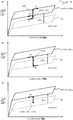
FIGS. 8A to 8C , a dotted line indicates a basic pedaling force characteristic line of the basic pedaling force characteristic F0 and a solid line indicates an operational reaction force characteristic line (hereinafter, called increased operational reaction force Fi) in a state that adjustment force ΔFa (i.e., operational reaction force) is added to the basic pedaling force characteristic F0 by the reaction force adding control mechanism. When the adjustment force ΔFa (i.e., the operational reaction force) is added by the reaction force adding control mechanism, it is shifted to the operational reaction force characteristic line in the return direction (arrow B') of the operational reaction force characteristic line of the increased operational reaction force Fi in every case that accelerator operation before the adjustment force ΔFa (i.e., the operational reaction force) is added is in the depression direction, in the return direction, or in a stopped state. When pedaling force being ΔFb or larger is applied as the driver continues to further depress the accelerator pedal against the operational reaction force, it is shifted to the operational reaction force characteristic line in the depressing direction (arrow A') of the operational reaction force characteristic line of the increased operational reaction force Fi. Accordingly, as long as pedaling force being ΔFb or larger is not applied to the accelerator pedal by the driver after the operational reaction force is added, the operational reaction force F is increased by the amount of ΔFa-ΔF as illustrated inFIG. 8A when the adjustment force ΔFa is added to the basic pedaling force characteristic F0 by the reaction force adding control mechanism while the accelerator pedal operation is in the depression direction (arrow A). When the adjustment force ΔFa is added to the basic pedaling force characteristic F0 by the reaction force adding control mechanism while the accelerator pedal operation is in the return direction (arrow B), the operational reaction force F is increased by the amount of ΔFa as illustrated inFIG. 8B . When the adjustment force ΔFa is added to the basic pedaling force characteristic F0 by the reaction force adding control mechanism while the accelerator pedal operation is in a stopped state, the operational reaction force F is increased by the amount in a range between ΔFa-ΔF and ΔFa as illustrated inFIG. 8C in accordance with the depression force of the accelerator pedal. In this manner, the increased amount of the operational reaction force F is varied in the range between ΔFa-ΔF and ΔFa depending on the operational direction of the accelerator pedal as being influenced by the hysteresis characteristic. - As described above, the same reaction force feeling cannot be provided to the driver even if the same operational reaction force at the same stroke amount is added to the accelerator pedal. Accordingly, when trying to recognize the eco-driving point, the driver feels a sense of strangeness as causing worsened operability. Since the above causes contribution to accelerator pedal flipping to disturb fuel consumption improvement, an accelerator pedal especially targeting eco-driving (i.e., fuel consumption improvement) cannot achieve the primary target.
- To address the above issues, the present invention provides an accelerator pedal apparatus having pedaling force characteristics with hysteresis capable of preventing operational feeling worsening accompanied by operational reaction force generation while clearly notifying an eco-driving point.
- To address the above issues, the present invention provides an accelerator pedal apparatus including an accelerator pedal, a hysteresis generating mechanism which provides a hysteresis pedaling force characteristic having larger pedaling force in a depression direction than that in a return direction, and a reaction force adding control mechanism which adds operational reaction force to operation of the accelerator pedal based on an adjustment force generation command from an upper unit. Here, the operational reaction force added by the reaction force adding control mechanism is not larger than a hysteresis amount generated by the hysteresis generating mechanism. The accelerator pedal apparatus may further include operation detection means which detects whether motion of the accelerator pedal is in the depression direction or the return direction. Here, the reaction force adding control mechanism adds the operational reaction force which is not larger than the hysteresis amount generated by the hysteresis generating mechanism in a case that the motion of the accelerator pedal is detected as being in the depression direction by the operation detection means while the adjustment force generation command is provided from the upper unit, and the reaction force adding control mechanism does not add the operational reaction force in a case that the motion of the accelerator pedal is detected as being in the return direction by the operation detection means while the adjustment force generation command is provided from the upper unit.
- According to the present invention, worsening of operational feeling corresponding to operational reaction force generation can be prevented with a structure that the operational reaction force is not added in a case that motion of the acceleration pedal is detected as being in the return direction at the time of receiving an adjustment force generation command from an upper unit.
-
-
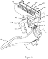
FIG. 1A is a perspective view andFIG. 1B is a side view illustrating a structure of an accelerator pedal apparatus of an embodiment according to the present invention; -
FIG. 2 is a perspective view illustrating an inner structure of the accelerator pedal apparatus of the embodiment according to the present invention; -
FIG. 3 is a schematic block diagram illustrating the structure of the accelerator pedal apparatus of the embodiment according to the present invention; -
FIG. 4 is an explanatory data flowchart for operation of the accelerator pedal apparatus of the embodiment according to the present invention; -
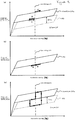
FIGS. 5A to 5C are explanatory graphs indicating operational reaction force characteristics for adjustment force generating operation when an adjustment force generation command eco is inputted to the accelerator pedal apparatus of the embodiment according to the present invention; whileFIG. 5A is an explanatory graph for variation of operational reaction force F when the adjustment force generation command eco is inputted during depressing,FIG. 5B is an explanatory graph for variation of the operational reaction force F when the adjustment force generation command eco is inputted during returning, andFIG. 5C is an explanatory graph for variation of the operational reaction force F under respective conditions; -
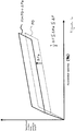
FIG. 6 is an explanatory graph indicating operational reaction force characteristics for adjustment force generating operation when the adjustment force generation command eco is inputted to an accelerator pedal apparatus of another embodiment according to the present invention; -
FIG. 7 is a graph indicating operational reaction force characteristics of a basic pedaling force characteristic F0; and -
FIGS. 8A to 8C are explanatory graphs indicating operational reaction force characteristics in a state that an adjustment force ΔFa is added to the basic pedaling force characteristic F0; whileFIG. 8A is an explanatory graph for variation of the operational reaction force F when the adjustment force ΔFa is added during depressing,FIG. 8B is an explanatory view for variation of the operational reaction force F when the adjustment force ΔFa is added during returning, andFIG. 8C is an explanatory view for variation of the operational reaction force F when the adjustment force ΔFa is added in a stopped state. - In the following, embodiments of the present invention will be described with reference to the drawings. An
accelerator pedal apparatus 10 of a present embodiment is adopted for an electrically controlled throttle system (i.e., a drive-by-wire system). As illustrated inFIGS. 1 to 3 , theaccelerator pedal apparatus 10 includes ahousing 11 which is fixed to a vehicle body of an automobile and the like, apedal arm 13 which has anaccelerator pedal 12 and which is swingably supported by thehousing 11, areturn spring 14 which exerts urging force to return thepedal arm 13 toward a rest position, ahysteresis generating mechanism 20 which generates hysteresis at pedaling force characteristics, an accelerator pedal position sensor (APS) 15 which detects a rotational angle of thepedal arm 13 due to operation of theaccelerator pedal 12 as the accelerator opening and which outputs the detected accelerator opening as an APS signal to an engine control unit (ECU) 50 being an upper unit, a reaction force addingcontrol mechanism 30 which varies operational reaction force F against operation of theaccelerator pedal 12 by generating operational reaction force, and a control unit (a control board) 40 which generates the operational reaction force by controlling the reaction force addingcontrol mechanism 30 based on an adjustment force generation command input from theECU 50 via a controller area network (CAN) communication line. - The
APS 15 is a position sensor which detects the rotational angle of thepedal arm 13 as the accelerator opening as being arranged around a swing axis L of thepedal arm 13 in asensor accommodating portion 11a formed in thehousing 11. For example, theAPS 15 being required to detect the rotational angle of thepedal arm 13 with high accuracy may adopt a non-contact type magnetic sensor which detects the rotational angle of the pedal arm as the accelerator opening by detecting variation of magnetic flux density with a Hall element while varying the magnetic flux density around the swing axis L in accordance with the swinging of thepedal arm 13. - The
APS 15 functions as accelerator position detection means which detects the accelerator opening of theaccelerator pedal 12 and outputs the accelerator opening to theECU 50. As being a main component to transmit accelerator operation to theECU 50, theAPS 15 is structured to be directly controlled by theECU 50 which is an upper unit. That is, as illustrated inFIG. 3 , reference voltage and ground voltage (GND) are supplied from theECU 50 to theAPS 15. The Hall element of theAPS 15 is driven at constant voltage by theECU 50. Further, the APS signal output from theAPS 15 is a voltage signal output in accordance with the magnetic flux density and is directly input to theECU 50 without passing through the control unit (control substrate) 40. Thus, driving is safely continued even in a case that a failure occurs at thecontrol unit 40. - As illustrated in
FIG. 2 , thehysteresis generating mechanism 20 includes afirst slider 61, asecond slider 62, and areturn spring 24 which are accommodated in thehousing 11. Thefirst slider 61 and thesecond slider 62 are engaged with anupper end portion 13a of thepedal arm 13 as being detachably attachable. Thefirst slider 61 and thesecond slider 62 generate frictional force with an inner wall face of thehousing 11 owing to depressing pedaling force of theaccelerator pedal 12. Thehysteresis generating mechanism 20 generates hysteresis on the pedaling force (i.e., a pedal load) owing to the frictional force and functions as first operational reaction force adding means which provides the basic pedaling force characteristic F0 as illustrated inFIG. 7 to the operation of theaccelerator pedal 12. The basic pedaling force characteristic F0 denotes the operational reaction force F in a state that operational reaction force (i.e., adjustment force ΔFa which is described later) is not added by controlling the reaction force addingcontrol mechanism 30. In this hysteresis characteristics, the operational reaction force F in the depression direction indicated by arrow A is larger than the operational reaction force F in the return direction indicated by arrow B. The difference between the operational reaction force F in the depression direction and the operational reaction force F in the return direction is to be a hysteresis amount ΔF. - The reaction force adding
control mechanism 30 functions as second operational reaction force adding means which adds adjustment force ΔFa being operational reaction force to the operation of theacceleration pedal 12 in addition to the basic pedaling force characteristic F0. As illustrated inFIG. 2 , the reaction force addingcontrol mechanism 30 includes atorque motor 31 of which rotation axis R is arranged at a position being different from the swing axis L of thepedal arm 13, areturn lever 32 which is arranged at the rotation axis R and which adds the adjustment force ΔFa as being contacted to thepedal arm 13, and a motor position sensor (MPS) 33. Thetorque motor 31 functions as a drive source for generating the adjustment force ΔFa. Thereturn lever 32 follows the swinging of thepedal arm 13 owing to magnetic spring action due to magnets (not illustrated) arranged in thetorque motor 31 even when motor torque (i.e., drive force) is not exerted by thetorque motor 31. Accordingly, a rotation shaft of thetorque motor 31 is rotated in accordance with the swinging of thepedal arm 13. On the other hand, when the motor torque (i.e., the drive force) is exerted by thetorque motor 31, the adjustment force ΔFa is exerted to thepedal arm 13 in a direction to push back toward the rest position owing to action of thereturn lever 32 against theupper end portion 13a of thepedal arm 13. - The
MPS 33 is arranged at thesensor accommodating portion 11b formed at thehousing 11. TheMPS 33 functions as motor position detection means which detects a rotational angle of thetorque motor 31 as a motor angle and outputs the motor angle to thecontrol unit 40. Since the rotation shaft of thetorque motor 31 is rotated in accordance with the swinging of thepedal arm 13, the motor angle output from theMPS 33 is increased with depressing of thepedal arm 13 and is decreased with returning of thepedal arm 13. Here, theMPS 33 may adopt a sensor of a contact type or a non-contact type. - The
control unit 40 functions as reaction force control means which adds the adjustment force ΔFa by controlling driving of thetorque motor 31. As illustrated inFIG. 3 , thecontrol unit 40 includes adrive circuit 41 which drives thetorque motor 31 with a PWM signal, acurrent detection circuit 42 which detects an actual motor current value being an actual current value flowing through thetorque motor 31, amicrocomputer 43 which controls generation of the adjustment force ΔFa utilizing thetorque motor 31 being the drive source, apower source circuit 44 which supplies power from a battery (not illustrated) to themicrocomputer 43, acommunication interface circuit 45 being an interface circuit connected to a CAN communication line, and anMPS input circuit 46 which inputs, to themicrocomputer 43, the MPS signal output from theMPS 33. - Next, operation of adjustment force generation in the
accelerator pedal apparatus 10 according to the present embodiment will be described with reference toFIGS. 4 and5 . - When the need for inviting driver's attention arises based on various information regarding driving situations, the
ECU 50 outputs the adjustment force generation command instructing to generate the adjustment force ΔFa against theaccelerator pedal apparatus 10 to the accelerator pedal apparatus via the CAN communication line. For example, the adjustment force generation command to be output from theECU 50 is output when it is determined that fuel consumption is to be worsened if theaccelerator pedal 12 is further depressed based on evaluation of driving situations (engine speed, vehicle speed, a load, and the like). The accelerator opening of theaccelerator pedal 12 at that time is to be the eco-driving point. - The adjustment force generation command input to the
accelerator pedal apparatus 10 via the CAN communication line is input to themicrocomputer 43 via thecommunication interface circuit 45 of thecontrol unit 40. Themicrocomputer 43 to which the adjustment force generation command is input performs an operational direction detection process S1 to detect the operational direction of theaccelerator pedal 12 and an adjustment force determination process S2 to determine magnitude of the adjustment force ΔFa which is to be generated by the reaction force addingcontrol mechanism 30. - The operational direction detection process S1 is performed by detecting variation of the motor angle in each unit time input from the
MPS 33 via theMPS input circuit 46. When the difference of the motor angle is positive with depressing of thepedal arm 13, it is detected as being in the depression direction. When the difference of the motor angle is negative with returning of thepedal arm 13, it is detected as being in the return direction. Here, when thepedal arm 13 is stopped without variation of the motor angle, it is detected as being in the return direction. In the operational direction detection process S1, it is only required to detect the operational direction. Therefore, it is also possible to adopt an APS signal output from theAPS 15 instead of the motor angle output from theMPS 33. Alternatively, it is also possible to adopt another sensor capable of detecting the operational direction. Here, theMPS 33 and theAPS 15 are examples of operation detection means. Further, since the adjustment force generation command is input at irregular timing, it is preferable to continuously perform the operational direction detection process S1. - The adjustment force determination process S2 determines an adjustment force instruction value indicating magnitude of the adjustment force ΔFa based on the input adjustment force generation command and the operational direction detected in the operational direction detection process S1. In the adjustment force determination process S2, when the operational direction detected in the operational direction detection process S1 is the depression direction, the adjustment force instruction value is determined as the hysteresis amount ΔF of the basic pedaling force characteristic F0 which is generated by the
hysteresis generating mechanism 20. - Next, the
microcomputer 43 performs a motor current calculation process S3 to calculate a target current value for driving themotor torque 31. Themicrocomputer 43 previously stores a torque-current conversion map in which the current value to be applied to thetorque motor 31 to obtain the target adjustment force ΔFa and the motor angle of thetorque motor 31 are corresponded. Themicrocomputer 43 calculates the target current value to be applied to thetorque motor 31 from the determined adjustment force instruction value ΔF by utilizing the torque-current conversion map as the motor current calculation process S3. - The target current value calculated in the motor current calculation process S3 is compared with the actual current value of the
torque motor 31 detected by thecurrent detection circuit 42 in motor drive control S4. By performing the motor drive control S4, the difference between the target current value and the actual current value is calculated as the PWM signal as a required current value to be applied to thetorque motor 31. Further, in the motor drive control S4, the PWM signal is output to thedrive circuit 41 as being corrected in accordance with actual battery voltage while comparing the actual battery voltage being the current power voltage with referential battery voltage. - The PWM signal is input to the
drive circuit 41 from themicrocomputer 43 as a required current value, and then, feedback control is performed with the actual motor current value detected by thecurrent detection circuit 42 while driving thetorque motor 31. Accordingly, the adjustment force ΔFa being the same as the hysteresis amount ΔF of the basic pedaling force characteristic F0 is generated by thetorque motor 31, so that the adjustment force ΔFa is added to the basic pedaling force characteristic F0. InFIG. 5A , a dotted line indicates an operational reaction force characteristic line of the basic pedaling force characteristic F0 and a solid line indicates an operational reaction force characteristic line (hereinafter, called increased operational reaction force Fi) in a state that the adjustment force ΔFa is added to the basic pedaling force characteristic F0 by the reaction force addingcontrol mechanism 30. - In a case that the adjustment force ΔFa being the same as the hysteresis amount ΔF of the basic pedaling force characteristic F0 is added to the basic pedaling force characteristic F0 as described above, the pedaling force F in the depression direction indicated by dotted arrow A in the basic pedaling force characteristic F0 and the pedaling force F in the return direction indicated by arrow B' in the reaction-force-increased pedaling force Fi (i.e., the increased operational reaction force Fi) are to be matched as illustrated in
FIG. 5A . - As described above, in a case that the adjustment force ΔFa being the operational force is added to the basic pedaling force characteristic F0 by the reaction force adding
control mechanism 30, the pedaling force is shifted to the operational reaction force characteristic line in the return direction of the operational reaction force characteristic line (arrow B'). Accordingly, in a case that the adjustment force ΔFa is added so that the pedaling force F in the depression direction indicated by dotted arrow A in the basic pedaling force characteristic F0 and the pedaling force F in the return direction indicated by arrow B' in the reaction-force-increased pedaling force Fi (i.e., the increased operational reaction force Fi) are to be overlapped, there is no feeling that theaccelerator pedal 12 is bounced or returned even when the adjustment force is generated. When the driver tries to further depress theaccelerator pedal 12, the pedaling force being larger than the adjustment force ΔFa is further required for depressing theaccelerator pedal 12 as the operational reaction force F indicated by arrow A' in the depression direction of the operational reaction force characteristic line. Since the pedaling force required to depress theaccelerator pedal 12 becomes large, the driver cannot depress theaccelerator pedal 12 with the same as before and feels a wall-like sense (a sense of resistance). However, when theaccelerator pedal 12 is continuously depressed with the pedaling force being larger than the adjustment force ΔFa, the pedaling force characteristic is shifted to arrow A' of the operational reaction force characteristic line in the depression direction. Thus, since bouncing of theaccelerator pedal 12 is prevented, it is possible to naturally invite driver's attention while clearly notifying the eco-driving point without losing operational feeling. In addition, further depressing can be performed while proving the wall-like sense to theaccelerator pedal 12. - In the present embodiment, the adjustment force ΔFa is set to be equal to the hysteresis amount ΔF when the operational direction detected in the operational direction detection process S1 is the depression direction. Here, it is preferable that the adjustment force ΔFa is not smaller than a half of the hysteresis amount ΔF and not larger than the hysteresis amount ΔF, as illustrated in
FIG. 6 . That is, as long as the adjustment force ΔFa is smaller than the hysteresis amount ΔF as illustrated inFIG. 6 , the operational reaction force F of the increased operational reaction force Fi in the return direction falls below the pedaling force F of the basic pedaling force characteristic F0 in the depression direction. Accordingly, operational feeling is not worsened without having feeling of bouncing or returning of theaccelerator pedal 12. However, when the adjustment force ΔFa is set to be extremely small compared to the hysteresis amount ΔF, the wall-like sense cannot be obtained at the time of further depressing theaccelerator pedal 12. - In the adjustment force determination process S2, when the operational direction detected in the operational direction detection process S1 is the return direction, the
microcomputer 43 does not determine the adjustment force instruction value and does not have the reaction force addingcontrol mechanism 30 generate the adjustment force ΔFa. Accordingly, even when the adjustment instruction command is input, the operational reaction force F in the return direction indicated by arrow B at the basic pedaling force characteristic F0 does not vary, as illustrated inFIG. 5B . Thus, operational feeling is not worsened without having feeling of bouncing or returning of theaccelerator pedal 12. - Here, once the adjustment force generation command is input, the adjustment force generation command is maintained in the
microcomputer 43 until an adjustment force cancellation command to instruct cancellation of the adjustment force ΔFa is input. Accordingly, in a case that the adjustment force ΔFa is not generated by the reaction force addingcontrol mechanism 30 without determining the adjustment force instruction value in the adjustment force determination process S2 and that the depression direction is detected in the operational direction detection process S1 while the adjustment force generation command is maintained, the abovementioned adjustment force determination process S2 is performed again and the adjustment force ΔFa being the same as the hysteresis amount ΔF of the basic pedaling force characteristic F0 is to be added to the basic pedaling force characteristic F0. That is, even in a case that the operational direction is once detected as being the return direction in the operational direction detection process S1 and that the adjustment force ΔFa is not generated by the reaction force addingcontrol mechanism 30 without determining the adjustment force instruction value, the operational direction is detected as being the depression direction in the operational direction detection process S1 when the accelerator opening arrives at the eco-driving point with further depression of theaccelerator pedal 12. Then, the adjustment force ΔFa is added to the basic pedaling force characteristic F0 by the reaction force addingcontrol mechanism 30 as illustrated inFIG. 5C . In contrast, in a case that the adjustment force ΔFa is generated by the reaction force addingcontrol mechanism 30 and that the return direction is detected in the operational direction detection process S1, adding of the adjustment force ΔFa by the reaction force addingcontrol mechanism 30 is cancelled, as illustrated inFIG. 5C . Accordingly, when theaccelerator pedal 12 is depressed again at the accelerator opening being equal to the eco-driving point or larger, the operational direction is detected as being the depressing direction in the operational direction detection process S1 and the adjustment force ΔFa is to be added to the basic pedaling force characteristic F0 by the reaction force addingcontrol mechanism 30. - In the present embodiment, the operational direction detection process S1 and the adjustment force determination process S2 are performed by the
microcomputer 43 of theaccelerator pedal apparatus 10. Here, it is also possible that theECU 50 being the upper unit performs either or both of the operational direction detection process S1 and the adjustment force determination process S2. In this case, it is considered that an accelerator pedal apparatus of the present invention includes the function to perform the operational direction detection process S1 and the adjustment force determination process S2 at theECU 50. - Here, not limited to the above embodiments, the present invention may be appropriately modified within the technical scope of the present invention. Further, not limited to the above embodiments, the number, location, shape and the like of the respective structural members may be modified appropriately for actualizing the present invention. Here, in each drawing, the same numeral is given to the same structural element.
-
- 10
- Accelerator pedal apparatus
- 11
- Housing
- 11a, 11b
- Sensor accommodating portion
- 12
- Accelerator pedal
- 13
- Pedal arm
- 13a
- Upper end portion
- 14
- Return spring
- 15
- Accelerator position sensor (APS)
- 20
- Hysteresis generating mechanism
- 24
- Return spring
- 30
- Reaction force adding control mechanism
- 31
- Torque motor
- 32
- Return lever
- 33
- Motor position sensor (MPS)
- 40
- Control unit (Control board)
- 41
- Drive circuit
- 42
- Current detection circuit
- 43
- Microcomputer
- 44
- Power source circuit
- 45
- Communication interface circuit
- 46
- MPS input circuit
- 50
- Engine control unit (EUC)
- 61
- First slider
- 62
- Second slider
Claims (2)
- An accelerator pedal apparatus, comprising:an accelerator pedal;a hysteresis generating mechanism which provides a hysteresis pedaling force characteristic having larger pedaling force in a depression direction than that in a return direction; anda reaction force adding control mechanism which adds operational reaction force to operation of the accelerator pedal based on an adjustment force generation command from an upper unit;wherein the operational reaction force added by the reaction force adding control mechanism is not larger than a hysteresis amount generated by the hysteresis generating mechanism.
- The accelerator pedal apparatus according to claim 1, further comprising operation detection means which detects whether motion of the accelerator pedal is in the depression direction or the return direction;
wherein the reaction force adding control mechanism adds the operational reaction force which is not larger than the hysteresis amount generated by the hysteresis generating mechanism in a case that the motion of the accelerator pedal is detected as being in the depression direction by the operation detection means while the adjustment force generation command is provided from the upper unit; and
the reaction force adding control mechanism does not add the operational reaction force in a case that the motion of the accelerator pedal is detected as being in the return direction by the operation detection means while the adjustment force generation command is provided from the upper unit.
Applications Claiming Priority (1)
| Application Number | Priority Date | Filing Date | Title |
|---|---|---|---|
| JP2011034897A JP5740175B2 (en) | 2011-02-21 | 2011-02-21 | Accelerator pedal device |
Publications (2)
| Publication Number | Publication Date |
|---|---|
| EP2490093A1 true EP2490093A1 (en) | 2012-08-22 |
| EP2490093B1 EP2490093B1 (en) | 2016-08-03 |
Family
ID=45656283
Family Applications (1)
| Application Number | Title | Priority Date | Filing Date |
|---|---|---|---|
| EP12156332.4A Active EP2490093B1 (en) | 2011-02-21 | 2012-02-21 | Accelerator pedal apparatus |
Country Status (3)
| Country | Link |
|---|---|
| US (1) | US8521360B2 (en) |
| EP (1) | EP2490093B1 (en) |
| JP (1) | JP5740175B2 (en) |
Cited By (1)
| Publication number | Priority date | Publication date | Assignee | Title |
|---|---|---|---|---|
| EP4029714A1 (en) * | 2021-01-13 | 2022-07-20 | Mazda Motor Corporation | Driving assistance device |
Families Citing this family (11)
| Publication number | Priority date | Publication date | Assignee | Title |
|---|---|---|---|---|
| JP5806480B2 (en) * | 2011-02-23 | 2015-11-10 | 株式会社ミクニ | Accelerator pedal device |
| DE102013205281A1 (en) | 2013-01-29 | 2014-07-31 | Robert Bosch Gmbh | An accelerator pedal unit |
| KR101406533B1 (en) * | 2013-04-16 | 2014-06-12 | 기아자동차주식회사 | Active control method of accelerator pedal effort |
| JP6304559B2 (en) * | 2015-03-04 | 2018-04-04 | 株式会社ホンダロック | Reaction force output device |
| JP6198768B2 (en) * | 2015-04-27 | 2017-09-20 | 本田技研工業株式会社 | Pedal reaction force applying device |
| DE102015109810B4 (en) * | 2015-06-19 | 2025-07-10 | HELLA GmbH & Co. KGaA | Accelerator pedal unit for a motor vehicle |
| JP7207269B2 (en) * | 2019-11-11 | 2023-01-18 | トヨタ自動車株式会社 | Pedal reaction force controller |
| KR102829327B1 (en) * | 2020-11-06 | 2025-07-02 | 현대자동차주식회사 | Organ type electronic brake pedal apparatus |
| KR102898372B1 (en) | 2020-11-09 | 2025-12-09 | 현대자동차주식회사 | Organ type electronic brake pedal apparatus |
| CN112896122A (en) * | 2021-03-05 | 2021-06-04 | 南京经纬达汽车科技有限公司 | Pedal feel simulation device and control method thereof |
| JP7694331B2 (en) * | 2021-10-21 | 2025-06-18 | 株式会社デンソー | Reaction force application device |
Citations (3)
| Publication number | Priority date | Publication date | Assignee | Title |
|---|---|---|---|---|
| EP1375232A1 (en) * | 2002-06-20 | 2004-01-02 | Nissan Motor Co., Ltd. | Accelerator pedal device |
| JP2010052721A (en) | 2008-07-31 | 2010-03-11 | Nissan Motor Co Ltd | Accelerator pedalling force control device and method |
| WO2010130606A1 (en) * | 2009-05-15 | 2010-11-18 | Conti Temic Microelectronic Gmbh | Speed regulation method and device |
Family Cites Families (7)
| Publication number | Priority date | Publication date | Assignee | Title |
|---|---|---|---|---|
| US6240801B1 (en) * | 1998-03-20 | 2001-06-05 | Oiles Corporation | Friction damper and pedal device for vehicle having the friction damper |
| US7237453B2 (en) * | 2002-07-08 | 2007-07-03 | Siemens Ag | Acceleration pedal module with controllable friction device |
| JP2004314871A (en) | 2003-04-18 | 2004-11-11 | Nissan Motor Co Ltd | Accelerator pedal depression force control device |
| JP4367089B2 (en) * | 2003-10-30 | 2009-11-18 | 日産自動車株式会社 | Accelerator pedal force control device |
| JP5381321B2 (en) * | 2008-07-31 | 2014-01-08 | 日産自動車株式会社 | Accelerator pedal force control device |
| JP5452108B2 (en) * | 2008-10-06 | 2014-03-26 | 株式会社ミクニ | Accelerator pedal device |
| JP5481933B2 (en) * | 2009-05-25 | 2014-04-23 | 日産自動車株式会社 | Accelerator pedal force control device |
-
2011
- 2011-02-21 JP JP2011034897A patent/JP5740175B2/en not_active Expired - Fee Related
-
2012
- 2012-02-21 EP EP12156332.4A patent/EP2490093B1/en active Active
- 2012-02-21 US US13/400,960 patent/US8521360B2/en active Active
Patent Citations (4)
| Publication number | Priority date | Publication date | Assignee | Title |
|---|---|---|---|---|
| EP1375232A1 (en) * | 2002-06-20 | 2004-01-02 | Nissan Motor Co., Ltd. | Accelerator pedal device |
| JP2010052721A (en) | 2008-07-31 | 2010-03-11 | Nissan Motor Co Ltd | Accelerator pedalling force control device and method |
| WO2010133915A1 (en) * | 2008-07-31 | 2010-11-25 | Nissan Motor Co., Ltd. | Accelerator-pedal reaction force control apparatus |
| WO2010130606A1 (en) * | 2009-05-15 | 2010-11-18 | Conti Temic Microelectronic Gmbh | Speed regulation method and device |
Cited By (1)
| Publication number | Priority date | Publication date | Assignee | Title |
|---|---|---|---|---|
| EP4029714A1 (en) * | 2021-01-13 | 2022-07-20 | Mazda Motor Corporation | Driving assistance device |
Also Published As
| Publication number | Publication date |
|---|---|
| US20120216652A1 (en) | 2012-08-30 |
| JP5740175B2 (en) | 2015-06-24 |
| EP2490093B1 (en) | 2016-08-03 |
| US8521360B2 (en) | 2013-08-27 |
| JP2012171475A (en) | 2012-09-10 |
Similar Documents
| Publication | Publication Date | Title |
|---|---|---|
| EP2490093B1 (en) | Accelerator pedal apparatus | |
| US8738261B2 (en) | Accelerator pedal apparatus | |
| US8660746B2 (en) | Accelerator pedal apparatus | |
| JP7258919B2 (en) | accelerator pedal device | |
| JP5728563B2 (en) | Reaction force pedal device | |
| KR20140102212A (en) | Method and control device for controlling a haptic accelerator pedal of a motor vehicle by means of a position control | |
| JP6198768B2 (en) | Pedal reaction force applying device | |
| JP6033197B2 (en) | Reaction force output device | |
| US7946191B2 (en) | Accelerator pedal system | |
| US9783054B2 (en) | Accelerator pedal information feedback system | |
| JP2006111174A (en) | Vehicle accelerator pedal control device and vehicle control device | |
| JP2018071395A (en) | Drive force control device | |
| JP2016113971A (en) | Driving force control device for vehicle | |
| JP2010137584A (en) | Accelerator stepping force control device | |
| JP2012245853A (en) | Accelerator | |
| JP2016159836A (en) | Reaction force output device | |
| JP2023060759A (en) | Driving assistance control device | |
| JP2011256721A (en) | Throttle valve control device | |
| JP2004132252A (en) | Vehicle speed limiting device | |
| JP2016159838A (en) | Reaction force output device |
Legal Events
| Date | Code | Title | Description |
|---|---|---|---|
| PUAI | Public reference made under article 153(3) epc to a published international application that has entered the european phase |
Free format text: ORIGINAL CODE: 0009012 |
|
| AK | Designated contracting states |
Kind code of ref document: A1 Designated state(s): AL AT BE BG CH CY CZ DE DK EE ES FI FR GB GR HR HU IE IS IT LI LT LU LV MC MK MT NL NO PL PT RO RS SE SI SK SM TR |
|
| AX | Request for extension of the european patent |
Extension state: BA ME |
|
| 17P | Request for examination filed |
Effective date: 20130222 |
|
| GRAP | Despatch of communication of intention to grant a patent |
Free format text: ORIGINAL CODE: EPIDOSNIGR1 |
|
| INTG | Intention to grant announced |
Effective date: 20151009 |
|
| GRAS | Grant fee paid |
Free format text: ORIGINAL CODE: EPIDOSNIGR3 |
|
| GRAP | Despatch of communication of intention to grant a patent |
Free format text: ORIGINAL CODE: EPIDOSNIGR1 |
|
| INTG | Intention to grant announced |
Effective date: 20160309 |
|
| GRAA | (expected) grant |
Free format text: ORIGINAL CODE: 0009210 |
|
| AK | Designated contracting states |
Kind code of ref document: B1 Designated state(s): AL AT BE BG CH CY CZ DE DK EE ES FI FR GB GR HR HU IE IS IT LI LT LU LV MC MK MT NL NO PL PT RO RS SE SI SK SM TR |
|
| REG | Reference to a national code |
Ref country code: GB Ref legal event code: FG4D |
|
| REG | Reference to a national code |
Ref country code: CH Ref legal event code: EP Ref country code: AT Ref legal event code: REF Ref document number: 817735 Country of ref document: AT Kind code of ref document: T Effective date: 20160815 |
|
| REG | Reference to a national code |
Ref country code: IE Ref legal event code: FG4D |
|
| REG | Reference to a national code |
Ref country code: DE Ref legal event code: R096 Ref document number: 602012021143 Country of ref document: DE |
|
| REG | Reference to a national code |
Ref country code: NL Ref legal event code: MP Effective date: 20160803 |
|
| REG | Reference to a national code |
Ref country code: LT Ref legal event code: MG4D |
|
| REG | Reference to a national code |
Ref country code: FR Ref legal event code: PLFP Year of fee payment: 6 |
|
| REG | Reference to a national code |
Ref country code: AT Ref legal event code: MK05 Ref document number: 817735 Country of ref document: AT Kind code of ref document: T Effective date: 20160803 |
|
| PG25 | Lapsed in a contracting state [announced via postgrant information from national office to epo] |
Ref country code: HR Free format text: LAPSE BECAUSE OF FAILURE TO SUBMIT A TRANSLATION OF THE DESCRIPTION OR TO PAY THE FEE WITHIN THE PRESCRIBED TIME-LIMIT Effective date: 20160803 Ref country code: IS Free format text: LAPSE BECAUSE OF FAILURE TO SUBMIT A TRANSLATION OF THE DESCRIPTION OR TO PAY THE FEE WITHIN THE PRESCRIBED TIME-LIMIT Effective date: 20161203 Ref country code: IT Free format text: LAPSE BECAUSE OF FAILURE TO SUBMIT A TRANSLATION OF THE DESCRIPTION OR TO PAY THE FEE WITHIN THE PRESCRIBED TIME-LIMIT Effective date: 20160803 Ref country code: LT Free format text: LAPSE BECAUSE OF FAILURE TO SUBMIT A TRANSLATION OF THE DESCRIPTION OR TO PAY THE FEE WITHIN THE PRESCRIBED TIME-LIMIT Effective date: 20160803 Ref country code: NO Free format text: LAPSE BECAUSE OF FAILURE TO SUBMIT A TRANSLATION OF THE DESCRIPTION OR TO PAY THE FEE WITHIN THE PRESCRIBED TIME-LIMIT Effective date: 20161103 Ref country code: RS Free format text: LAPSE BECAUSE OF FAILURE TO SUBMIT A TRANSLATION OF THE DESCRIPTION OR TO PAY THE FEE WITHIN THE PRESCRIBED TIME-LIMIT Effective date: 20160803 Ref country code: NL Free format text: LAPSE BECAUSE OF FAILURE TO SUBMIT A TRANSLATION OF THE DESCRIPTION OR TO PAY THE FEE WITHIN THE PRESCRIBED TIME-LIMIT Effective date: 20160803 Ref country code: FI Free format text: LAPSE BECAUSE OF FAILURE TO SUBMIT A TRANSLATION OF THE DESCRIPTION OR TO PAY THE FEE WITHIN THE PRESCRIBED TIME-LIMIT Effective date: 20160803 |
|
| PG25 | Lapsed in a contracting state [announced via postgrant information from national office to epo] |
Ref country code: PT Free format text: LAPSE BECAUSE OF FAILURE TO SUBMIT A TRANSLATION OF THE DESCRIPTION OR TO PAY THE FEE WITHIN THE PRESCRIBED TIME-LIMIT Effective date: 20161205 Ref country code: PL Free format text: LAPSE BECAUSE OF FAILURE TO SUBMIT A TRANSLATION OF THE DESCRIPTION OR TO PAY THE FEE WITHIN THE PRESCRIBED TIME-LIMIT Effective date: 20160803 Ref country code: ES Free format text: LAPSE BECAUSE OF FAILURE TO SUBMIT A TRANSLATION OF THE DESCRIPTION OR TO PAY THE FEE WITHIN THE PRESCRIBED TIME-LIMIT Effective date: 20160803 Ref country code: LV Free format text: LAPSE BECAUSE OF FAILURE TO SUBMIT A TRANSLATION OF THE DESCRIPTION OR TO PAY THE FEE WITHIN THE PRESCRIBED TIME-LIMIT Effective date: 20160803 Ref country code: GR Free format text: LAPSE BECAUSE OF FAILURE TO SUBMIT A TRANSLATION OF THE DESCRIPTION OR TO PAY THE FEE WITHIN THE PRESCRIBED TIME-LIMIT Effective date: 20161104 Ref country code: AT Free format text: LAPSE BECAUSE OF FAILURE TO SUBMIT A TRANSLATION OF THE DESCRIPTION OR TO PAY THE FEE WITHIN THE PRESCRIBED TIME-LIMIT Effective date: 20160803 Ref country code: SE Free format text: LAPSE BECAUSE OF FAILURE TO SUBMIT A TRANSLATION OF THE DESCRIPTION OR TO PAY THE FEE WITHIN THE PRESCRIBED TIME-LIMIT Effective date: 20160803 |
|
| PG25 | Lapsed in a contracting state [announced via postgrant information from national office to epo] |
Ref country code: RO Free format text: LAPSE BECAUSE OF FAILURE TO SUBMIT A TRANSLATION OF THE DESCRIPTION OR TO PAY THE FEE WITHIN THE PRESCRIBED TIME-LIMIT Effective date: 20160803 Ref country code: EE Free format text: LAPSE BECAUSE OF FAILURE TO SUBMIT A TRANSLATION OF THE DESCRIPTION OR TO PAY THE FEE WITHIN THE PRESCRIBED TIME-LIMIT Effective date: 20160803 |
|
| REG | Reference to a national code |
Ref country code: DE Ref legal event code: R097 Ref document number: 602012021143 Country of ref document: DE |
|
| PG25 | Lapsed in a contracting state [announced via postgrant information from national office to epo] |
Ref country code: CZ Free format text: LAPSE BECAUSE OF FAILURE TO SUBMIT A TRANSLATION OF THE DESCRIPTION OR TO PAY THE FEE WITHIN THE PRESCRIBED TIME-LIMIT Effective date: 20160803 Ref country code: DK Free format text: LAPSE BECAUSE OF FAILURE TO SUBMIT A TRANSLATION OF THE DESCRIPTION OR TO PAY THE FEE WITHIN THE PRESCRIBED TIME-LIMIT Effective date: 20160803 Ref country code: SM Free format text: LAPSE BECAUSE OF FAILURE TO SUBMIT A TRANSLATION OF THE DESCRIPTION OR TO PAY THE FEE WITHIN THE PRESCRIBED TIME-LIMIT Effective date: 20160803 Ref country code: BE Free format text: LAPSE BECAUSE OF FAILURE TO SUBMIT A TRANSLATION OF THE DESCRIPTION OR TO PAY THE FEE WITHIN THE PRESCRIBED TIME-LIMIT Effective date: 20160803 Ref country code: SK Free format text: LAPSE BECAUSE OF FAILURE TO SUBMIT A TRANSLATION OF THE DESCRIPTION OR TO PAY THE FEE WITHIN THE PRESCRIBED TIME-LIMIT Effective date: 20160803 Ref country code: BG Free format text: LAPSE BECAUSE OF FAILURE TO SUBMIT A TRANSLATION OF THE DESCRIPTION OR TO PAY THE FEE WITHIN THE PRESCRIBED TIME-LIMIT Effective date: 20161103 |
|
| PLBE | No opposition filed within time limit |
Free format text: ORIGINAL CODE: 0009261 |
|
| STAA | Information on the status of an ep patent application or granted ep patent |
Free format text: STATUS: NO OPPOSITION FILED WITHIN TIME LIMIT |
|
| 26N | No opposition filed |
Effective date: 20170504 |
|
| PG25 | Lapsed in a contracting state [announced via postgrant information from national office to epo] |
Ref country code: SI Free format text: LAPSE BECAUSE OF FAILURE TO SUBMIT A TRANSLATION OF THE DESCRIPTION OR TO PAY THE FEE WITHIN THE PRESCRIBED TIME-LIMIT Effective date: 20160803 |
|
| PG25 | Lapsed in a contracting state [announced via postgrant information from national office to epo] |
Ref country code: MC Free format text: LAPSE BECAUSE OF FAILURE TO SUBMIT A TRANSLATION OF THE DESCRIPTION OR TO PAY THE FEE WITHIN THE PRESCRIBED TIME-LIMIT Effective date: 20160803 |
|
| REG | Reference to a national code |
Ref country code: CH Ref legal event code: PL |
|
| PG25 | Lapsed in a contracting state [announced via postgrant information from national office to epo] |
Ref country code: LI Free format text: LAPSE BECAUSE OF NON-PAYMENT OF DUE FEES Effective date: 20170228 Ref country code: CH Free format text: LAPSE BECAUSE OF NON-PAYMENT OF DUE FEES Effective date: 20170228 |
|
| REG | Reference to a national code |
Ref country code: IE Ref legal event code: MM4A |
|
| PG25 | Lapsed in a contracting state [announced via postgrant information from national office to epo] |
Ref country code: LU Free format text: LAPSE BECAUSE OF NON-PAYMENT OF DUE FEES Effective date: 20170221 |
|
| REG | Reference to a national code |
Ref country code: FR Ref legal event code: PLFP Year of fee payment: 7 |
|
| PG25 | Lapsed in a contracting state [announced via postgrant information from national office to epo] |
Ref country code: IE Free format text: LAPSE BECAUSE OF NON-PAYMENT OF DUE FEES Effective date: 20170221 |
|
| PG25 | Lapsed in a contracting state [announced via postgrant information from national office to epo] |
Ref country code: MT Free format text: LAPSE BECAUSE OF NON-PAYMENT OF DUE FEES Effective date: 20170221 |
|
| PG25 | Lapsed in a contracting state [announced via postgrant information from national office to epo] |
Ref country code: AL Free format text: LAPSE BECAUSE OF FAILURE TO SUBMIT A TRANSLATION OF THE DESCRIPTION OR TO PAY THE FEE WITHIN THE PRESCRIBED TIME-LIMIT Effective date: 20160803 |
|
| RIC2 | Information provided on ipc code assigned after grant |
Ipc: B60K 26/02 20060101ALI20120622BHEP Ipc: G05G 5/03 20080401AFI20120622BHEP Ipc: G05G 1/30 20080401ALI20120622BHEP |
|
| PGFP | Annual fee paid to national office [announced via postgrant information from national office to epo] |
Ref country code: IE Payment date: 20190327 Year of fee payment: 15 |
|
| PG25 | Lapsed in a contracting state [announced via postgrant information from national office to epo] |
Ref country code: HU Free format text: LAPSE BECAUSE OF FAILURE TO SUBMIT A TRANSLATION OF THE DESCRIPTION OR TO PAY THE FEE WITHIN THE PRESCRIBED TIME-LIMIT; INVALID AB INITIO Effective date: 20120221 |
|
| PG25 | Lapsed in a contracting state [announced via postgrant information from national office to epo] |
Ref country code: CY Free format text: LAPSE BECAUSE OF NON-PAYMENT OF DUE FEES Effective date: 20160803 |
|
| PG25 | Lapsed in a contracting state [announced via postgrant information from national office to epo] |
Ref country code: MK Free format text: LAPSE BECAUSE OF FAILURE TO SUBMIT A TRANSLATION OF THE DESCRIPTION OR TO PAY THE FEE WITHIN THE PRESCRIBED TIME-LIMIT Effective date: 20160803 |
|
| PG25 | Lapsed in a contracting state [announced via postgrant information from national office to epo] |
Ref country code: TR Free format text: LAPSE BECAUSE OF FAILURE TO SUBMIT A TRANSLATION OF THE DESCRIPTION OR TO PAY THE FEE WITHIN THE PRESCRIBED TIME-LIMIT Effective date: 20160803 |
|
| GBPC | Gb: european patent ceased through non-payment of renewal fee |
Effective date: 20200221 |
|
| PG25 | Lapsed in a contracting state [announced via postgrant information from national office to epo] |
Ref country code: GB Free format text: LAPSE BECAUSE OF NON-PAYMENT OF DUE FEES Effective date: 20200221 |
|
| PGFP | Annual fee paid to national office [announced via postgrant information from national office to epo] |
Ref country code: FR Payment date: 20240103 Year of fee payment: 13 |
|
| PGFP | Annual fee paid to national office [announced via postgrant information from national office to epo] |
Ref country code: DE Payment date: 20241231 Year of fee payment: 14 |
|
| PG25 | Lapsed in a contracting state [announced via postgrant information from national office to epo] |
Ref country code: FR Free format text: LAPSE BECAUSE OF NON-PAYMENT OF DUE FEES Effective date: 20250228 |