EP2489985A1 - Metering infrastructure smart cards - Google Patents
Metering infrastructure smart cards Download PDFInfo
- Publication number
- EP2489985A1 EP2489985A1 EP12153976A EP12153976A EP2489985A1 EP 2489985 A1 EP2489985 A1 EP 2489985A1 EP 12153976 A EP12153976 A EP 12153976A EP 12153976 A EP12153976 A EP 12153976A EP 2489985 A1 EP2489985 A1 EP 2489985A1
- Authority
- EP
- European Patent Office
- Prior art keywords
- application programs
- smart
- card
- smart card
- controllable device
- Prior art date
- Legal status (The legal status is an assumption and is not a legal conclusion. Google has not performed a legal analysis and makes no representation as to the accuracy of the status listed.)
- Granted
Links
- 238000004891 communication Methods 0.000 claims description 20
- 238000012545 processing Methods 0.000 claims description 7
- 238000012423 maintenance Methods 0.000 claims description 6
- 230000003213 activating effect Effects 0.000 claims description 5
- 230000004913 activation Effects 0.000 claims description 5
- 230000006870 function Effects 0.000 description 5
- 238000010586 diagram Methods 0.000 description 3
- 238000000034 method Methods 0.000 description 3
- 230000003287 optical effect Effects 0.000 description 3
- 238000013459 approach Methods 0.000 description 2
- 238000012986 modification Methods 0.000 description 2
- 230000004048 modification Effects 0.000 description 2
- 239000004065 semiconductor Substances 0.000 description 2
- 230000005540 biological transmission Effects 0.000 description 1
- 230000001413 cellular effect Effects 0.000 description 1
- 238000004590 computer program Methods 0.000 description 1
- 238000013523 data management Methods 0.000 description 1
- 238000009826 distribution Methods 0.000 description 1
- 230000000694 effects Effects 0.000 description 1
- 230000005611 electricity Effects 0.000 description 1
- 239000000835 fiber Substances 0.000 description 1
- 239000012530 fluid Substances 0.000 description 1
- 238000009434 installation Methods 0.000 description 1
- 238000004519 manufacturing process Methods 0.000 description 1
- 230000008569 process Effects 0.000 description 1
- 230000008672 reprogramming Effects 0.000 description 1
- 239000007787 solid Substances 0.000 description 1
- 238000003860 storage Methods 0.000 description 1
- 238000012360 testing method Methods 0.000 description 1
- XLYOFNOQVPJJNP-UHFFFAOYSA-N water Substances O XLYOFNOQVPJJNP-UHFFFAOYSA-N 0.000 description 1
Images


Classifications
-
- G—PHYSICS
- G06—COMPUTING; CALCULATING OR COUNTING
- G06K—GRAPHICAL DATA READING; PRESENTATION OF DATA; RECORD CARRIERS; HANDLING RECORD CARRIERS
- G06K17/00—Methods or arrangements for effecting co-operative working between equipments covered by two or more of main groups G06K1/00 - G06K15/00, e.g. automatic card files incorporating conveying and reading operations
-
- G—PHYSICS
- G01—MEASURING; TESTING
- G01D—MEASURING NOT SPECIALLY ADAPTED FOR A SPECIFIC VARIABLE; ARRANGEMENTS FOR MEASURING TWO OR MORE VARIABLES NOT COVERED IN A SINGLE OTHER SUBCLASS; TARIFF METERING APPARATUS; MEASURING OR TESTING NOT OTHERWISE PROVIDED FOR
- G01D4/00—Tariff metering apparatus
- G01D4/002—Remote reading of utility meters
-
- Y—GENERAL TAGGING OF NEW TECHNOLOGICAL DEVELOPMENTS; GENERAL TAGGING OF CROSS-SECTIONAL TECHNOLOGIES SPANNING OVER SEVERAL SECTIONS OF THE IPC; TECHNICAL SUBJECTS COVERED BY FORMER USPC CROSS-REFERENCE ART COLLECTIONS [XRACs] AND DIGESTS
- Y02—TECHNOLOGIES OR APPLICATIONS FOR MITIGATION OR ADAPTATION AGAINST CLIMATE CHANGE
- Y02B—CLIMATE CHANGE MITIGATION TECHNOLOGIES RELATED TO BUILDINGS, e.g. HOUSING, HOUSE APPLIANCES OR RELATED END-USER APPLICATIONS
- Y02B90/00—Enabling technologies or technologies with a potential or indirect contribution to GHG emissions mitigation
- Y02B90/20—Smart grids as enabling technology in buildings sector
-
- Y—GENERAL TAGGING OF NEW TECHNOLOGICAL DEVELOPMENTS; GENERAL TAGGING OF CROSS-SECTIONAL TECHNOLOGIES SPANNING OVER SEVERAL SECTIONS OF THE IPC; TECHNICAL SUBJECTS COVERED BY FORMER USPC CROSS-REFERENCE ART COLLECTIONS [XRACs] AND DIGESTS
- Y04—INFORMATION OR COMMUNICATION TECHNOLOGIES HAVING AN IMPACT ON OTHER TECHNOLOGY AREAS
- Y04S—SYSTEMS INTEGRATING TECHNOLOGIES RELATED TO POWER NETWORK OPERATION, COMMUNICATION OR INFORMATION TECHNOLOGIES FOR IMPROVING THE ELECTRICAL POWER GENERATION, TRANSMISSION, DISTRIBUTION, MANAGEMENT OR USAGE, i.e. SMART GRIDS
- Y04S20/00—Management or operation of end-user stationary applications or the last stages of power distribution; Controlling, monitoring or operating thereof
- Y04S20/30—Smart metering, e.g. specially adapted for remote reading
Definitions
- the present invention relates generally to managing a metering infrastructure, and more particularly for managing and controlling devices in a metering infrastructure using deployed smart cards.
- AMI Advanced Metering Infrastructure
- MDM Meter Data Management
- a typical AMI may include a significant number of smart devices (e.g., meters, supervisory control and data acquisition "SCADA" devices, routers, etc.) having advanced (i.e., "smart") functional capabilities implemented with some type of computational system. Because many of these devices are heterogeneous in nature, providing different functions, being manufactured by different suppliers, etc., implementing and managing the devices within such an infrastructure poses a significant challenge.
- smart devices e.g., meters, supervisory control and data acquisition "SCADA” devices, routers, etc.
- an advanced metering infrastructure having a plurality of smart devices, each smart device being adapted to be controlled by a removable smart card, wherein each removable smart card includes: a computational platform capable of storing and executing program code; and a set of application programs having program code capable of being executed on the computational platform, wherein each of the set of application programs is implemented to control an aspect of an associated smart device into which the removable smart card is inserted.
- AMI advanced metering infrastructure
- SIM card generally refers to any portable card, device or token that includes a computational platform, such as an embedded integrated circuit.
- a computational platform such as an embedded integrated circuit.
- Common examples include SIMs (subscriber identity modules) commonly found in cell phones and other network devices, chip cards such as those provided by Gemalto®, etc.
- AMI advanced metering infrastructure
- computational functionality is implemented using software and firmware embedded within the different hardware devices that form the infrastructure.
- each meter may include special purpose hardware programmed to perform certain functions, e.g., manage meter readings, implement communication and security protocols, handle subscriber identification, etc.
- this greatly limits the flexibility of the infrastructure i.e., devices have to be manufactured, programmed and tested to meet rigorous specifications and protocols to ensure fluid operation.
- FIG. 1 depicts a schematic view of an AMI 10 having a plurality of smart devices, including smart meters 12, a router 14, a SCADA device 16 and a data aggregator 18.
- the smart devices form a network that is ultimately driven by a home office 20 via a back haul.
- the depicted set of devices is intended to show a simple example of an AMI, and the type and number of devices can vary depending on the particular application.
- Each smart device in the AMI 10 is equipped with a set of predefined functions that are controlled and/or implemented by a removable smart card 22a-f. Accordingly, some or all of the actual computational functionality is removed from each device and is implemented in the device's associated smart card 22a-f. As such, the "smart" features of the hardware devices do not need to be built into each device, but are instead located on an associated smart card 22a-f.
- an associated smart card e.g., card 22a
- a device e.g., meter 12
- this approach allows for the mass production of "generic" card controllable devices that can customized via a smart card 22a-f for specific customers, desired functionality, locations, etc., simply by inserting a smart card that is programmed to the installation's specific functionality requirements. Upgrades and changes to hardware functionality can be achieved by simply changing or reprogramming the smart card 22a-f.
- FIG. 2 depicts an illustrative schematic of a smart card 22 having a computational platform 24.
- Computational platform 24 may for example be implemented via an integrated circuit (not shown) that includes a processor, memory, I/O, and bus.
- an operating system 26 e.g., a Java Virtual Machine (JVM), having for instance a master controller 28 and an I/O controller.
- Master controller 28 facilitates the configuring and programming of the smart card 22, while I/O controller 30 facilitates communications with the associated hardware device via physical interface 44.
- a set of application programs 32 that perform functionality specific to the associated device into which the smart card 22 is inserted.
- application programs 32 include: (1) a communication module 34 for implementing communication protocols and methods (e.g., cellular, fiber, TCP/IP, etc.); (2) a security module 36 for implementing security protocols, establishing secure communications, providing encryption support, etc.; (3) an activation / subscriber information module 38 for activating an associated device, managing associated licenses, maintaining subscriber information, etc.; (4) a hardware control module 40 for controlling and managing actual device operations, e.g., scheduling and obtaining meter readings, relaying or retrieving readings over a network, etc.; and (5) a maintenance module 42 for handing errors, e.g., ensuring proper operation of the device, performing self tests, servicing problems, performing upgrades, etc. It is understood that the number and type of application programs 32 will depend upon the specific requirements of the associated hardware device.
- communication protocols and methods e.g., cellular, fiber, TCP/IP, etc.
- security module 36 for implementing security protocols, establishing secure communications, providing encryption support, etc.
- any type of computational platform 24 / operating system 26 could be utilized, including, e.g., Java, .NET, C++, a proprietary system, an open system, etc.
- Operating systems such as Java allow application programs 32 written in Java to be securely protected and tamperproof, thus providing a high level of inherent security.
- each of the application programs 32 are stored and executed within the smart card 22 itself, thus eliminating (or reducing) the need for a computational platform on the associated device. As such, most or all of the "smart" functionality is maintained and run on the smart card 22.
- the operating system 26 is automatically launched when the smart card 22 is inserted into an associated device and the device is powered on.
- the operating system 26 then launches master controller 28, which in turn launches one or more application programs 32, which may run continuously or be launched as needed.
- the hardware control module 40 may continuously run to collect a continuous stream of meter data while the maintenance module 42 may be launched as needed to install upgrades or check for errors.
- I/O controller 30 is likewise launched by the operating system 26 to allow the smart card to talk to the associated device.
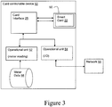
- FIG. 3 depicts an example of a card controllable device 50, such as a utility meter, configured for control by smart card 22.
- card controllable device 50 includes a physical slot 60 for receiving smart card 22.
- Smart card 22 can be inserted and removed as needed from physical slot 60 using a mechanical latch or the like.
- a card interface 25 that is configured to provide a communication channel between the inserted smart card 22 and one or more operational units 52, 54.
- card interface 25 may be adapted to receive instructions, data or control signals generated from applications running on the smart card 22, and relay the same to operational units 52, 54.
- card interface 25 may also be adapted to relay data from the operational units 52, 54 to the smart card 22, where the data can be processed.
- card controllable device 50 includes a first operational unit 52 for collecting meter data 58, e.g., power usage, error conditions, etc. Also included is a second operational unit 54 that provides input/output (I/O) functions to an associated network 56.
- smart card 22 may: (1) instruct operational unit 52 to collect meter readings every ten minutes, (2) store the readings in a temporary cache on the smart card 22, and (3) instruct operational unit 54 to transmit daily readings to the home office, e.g., at a predetermined time.
- the technical effects include a metering infrastructure having a plurality of smart devices in which some or all of the smart devices are controlled and managed by smart cards that include a computation platform and application programs for implementing the smart functionality of an associated device.
- aspects of the smart card 22 described herein can be implemented in the form of an entirely hardware embodiment, an entirely software embodiment or an embodiment containing both hardware and software elements.
- the operating system 26 and application programs 32 may be implemented in software, which includes but is not limited to firmware, resident software, microcode, etc.
- processing functions can take the form of a computer program product accessible from a computer-usable or computer-readable medium providing program code for use by or in connection with a computer platform resident on the smart card 22 or any instruction execution system (e.g., processing units).
- a computer-usable or computer readable medium can be any computer readable storage medium that can contain or store the program for use by or in connection with the computer, instruction execution system, apparatus, or device.
- a computer readable transmission medium may be utilized that can communicate, propagate or transport the program for use by or in connection with the computer, instruction execution system, apparatus, or device.
- the computer readable medium can be an electronic, magnetic, optical, electromagnetic, infrared, or semiconductor system (or apparatus or device).
- Examples of a computer-readable medium include a semiconductor or solid state memory, a random access memory (RAM), a read-only memory (ROM), a rigid magnetic disk and an optical disk.
- Current examples of optical disks include a compact disk - read only memory (CD-ROM), a compact disk - read/write (CD-R/W) and a digital video disc (DVD).
Abstract
Description
- The present invention relates generally to managing a metering infrastructure, and more particularly for managing and controlling devices in a metering infrastructure using deployed smart cards.
- Large scale smart infrastructures may incorporate a large number of smart devices. One such example is an Advanced Metering Infrastructure (AMI), which refers to systems that measure, collect and analyze energy usage, and interact with advanced devices such as electricity meters, gas meters, heat meters, cable meters and water meters, through various communication media either on request (on-demand) or on pre-defined schedules. These infrastructures include hardware, software, communications, consumer energy displays and controllers, customer associated systems, Meter Data Management (MDM) software, supplier and network distribution business systems, etc.
- A typical AMI may include a significant number of smart devices (e.g., meters, supervisory control and data acquisition "SCADA" devices, routers, etc.) having advanced (i.e., "smart") functional capabilities implemented with some type of computational system. Because many of these devices are heterogeneous in nature, providing different functions, being manufactured by different suppliers, etc., implementing and managing the devices within such an infrastructure poses a significant challenge.
- In one aspect of the present invention, a smart card for use in a card controllable device within a metering infrastructure is disclosed, the smart card comprising: a computational platform capable of storing and executing program code; and a set of application programs having program code capable of being executed on the computational platform, wherein each of the set of application programs is implemented to control an aspect of an associated card controllable device into which the smart card is inserted.
- In a further aspect, an advanced metering infrastructure (AMI) having a plurality of smart devices is disclosed, each smart device being adapted to be controlled by a removable smart card, wherein each removable smart card includes: a computational platform capable of storing and executing program code; and a set of application programs having program code capable of being executed on the computational platform, wherein each of the set of application programs is implemented to control an aspect of an associated smart device into which the removable smart card is inserted.
- In still a further aspect, a card controllable device for use in a metering infrastructure is provided, the card controllable device comprising: a set of operational units; a slot for receiving a smart card, wherein the smart card includes: a computational platform capable of storing and executing program code; and a set of application programs having program code capable of being executed on the computational platform, wherein each of the set of application programs is implemented to control aspects of the set of operational units; and a card interface for providing a communication channel between the smart card and the set of operational units.
- Various aspects and embodiments of the present invention will now be described in connection with the accompanying drawings, in which:
-
Figure 1 is a schematic diagram illustrating an AMI being managed using smart cards according to one embodiment of the present invention; -
Figure 2 is a schematic block diagram of a smart card according to one embodiment of the present invention; and -
Figure 3 shows a schematic diagram of a card controllable device according to one embodiment of the present invention. - Various embodiments of the present invention are directed to managing and controlling devices in a metering infrastructure using smart cards. For the purposes of this disclosure, the term "smart card" generally refers to any portable card, device or token that includes a computational platform, such as an embedded integrated circuit. Common examples include SIMs (subscriber identity modules) commonly found in cell phones and other network devices, chip cards such as those provided by Gemalto®, etc.
- In a typical advanced metering infrastructure (AMI), computational functionality is implemented using software and firmware embedded within the different hardware devices that form the infrastructure. For example, each meter may include special purpose hardware programmed to perform certain functions, e.g., manage meter readings, implement communication and security protocols, handle subscriber identification, etc. Unfortunately, as noted above, this greatly limits the flexibility of the infrastructure, i.e., devices have to be manufactured, programmed and tested to meet rigorous specifications and protocols to ensure fluid operation.
- Described herein is a more flexible approach to managing and controlling a smart infrastructure such as an AMI, in which computational functionality is moved from the hardware devices to portable smart cards.
Figure 1 depicts a schematic view of an AMI 10 having a plurality of smart devices, includingsmart meters 12, arouter 14, aSCADA device 16 and adata aggregator 18. The smart devices form a network that is ultimately driven by ahome office 20 via a back haul. Obviously, the depicted set of devices is intended to show a simple example of an AMI, and the type and number of devices can vary depending on the particular application. - Each smart device in the AMI 10 is equipped with a set of predefined functions that are controlled and/or implemented by a removable smart card 22a-f. Accordingly, some or all of the actual computational functionality is removed from each device and is implemented in the device's associated smart card 22a-f. As such, the "smart" features of the hardware devices do not need to be built into each device, but are instead located on an associated smart card 22a-f. Upon inserting an associated smart card (e.g., card 22a) into a device (e.g., meter 12), the smart functionality specific to the smart card becomes enabled on the device. Among other benefits, this approach allows for the mass production of "generic" card controllable devices that can customized via a smart card 22a-f for specific customers, desired functionality, locations, etc., simply by inserting a smart card that is programmed to the installation's specific functionality requirements. Upgrades and changes to hardware functionality can be achieved by simply changing or reprogramming the smart card 22a-f.
-
Figure 2 depicts an illustrative schematic of asmart card 22 having acomputational platform 24.Computational platform 24 may for example be implemented via an integrated circuit (not shown) that includes a processor, memory, I/O, and bus. Within thecomputational platform 24 is anoperating system 26, e.g., a Java Virtual Machine (JVM), having for instance amaster controller 28 and an I/O controller.Master controller 28 facilitates the configuring and programming of thesmart card 22, while I/O controller 30 facilitates communications with the associated hardware device viaphysical interface 44. Also included within thecomputational platform 24 are a set ofapplication programs 32 that perform functionality specific to the associated device into which thesmart card 22 is inserted. - In this illustrative embodiment,
application programs 32 include: (1) acommunication module 34 for implementing communication protocols and methods (e.g., cellular, fiber, TCP/IP, etc.); (2) asecurity module 36 for implementing security protocols, establishing secure communications, providing encryption support, etc.; (3) an activation / subscriber information module 38 for activating an associated device, managing associated licenses, maintaining subscriber information, etc.; (4) ahardware control module 40 for controlling and managing actual device operations, e.g., scheduling and obtaining meter readings, relaying or retrieving readings over a network, etc.; and (5) amaintenance module 42 for handing errors, e.g., ensuring proper operation of the device, performing self tests, servicing problems, performing upgrades, etc. It is understood that the number and type ofapplication programs 32 will depend upon the specific requirements of the associated hardware device. - It is understood that any type of
computational platform 24 /operating system 26 could be utilized, including, e.g., Java, .NET, C++, a proprietary system, an open system, etc. Operating systems such as Java allowapplication programs 32 written in Java to be securely protected and tamperproof, thus providing a high level of inherent security. - Accordingly, each of the
application programs 32 are stored and executed within thesmart card 22 itself, thus eliminating (or reducing) the need for a computational platform on the associated device. As such, most or all of the "smart" functionality is maintained and run on thesmart card 22. - In one illustrative embodiment, the
operating system 26 is automatically launched when thesmart card 22 is inserted into an associated device and the device is powered on. Theoperating system 26 then launchesmaster controller 28, which in turn launches one ormore application programs 32, which may run continuously or be launched as needed. For example, thehardware control module 40 may continuously run to collect a continuous stream of meter data while themaintenance module 42 may be launched as needed to install upgrades or check for errors. I/O controller 30 is likewise launched by theoperating system 26 to allow the smart card to talk to the associated device. -
Figure 3 depicts an example of a cardcontrollable device 50, such as a utility meter, configured for control bysmart card 22. In this example, cardcontrollable device 50 includes aphysical slot 60 for receivingsmart card 22. Smartcard 22 can be inserted and removed as needed fromphysical slot 60 using a mechanical latch or the like. Also included is acard interface 25 that is configured to provide a communication channel between the insertedsmart card 22 and one or moreoperational units card interface 25 may be adapted to receive instructions, data or control signals generated from applications running on thesmart card 22, and relay the same tooperational units card interface 25 may also be adapted to relay data from theoperational units smart card 22, where the data can be processed. - In this example, card
controllable device 50 includes a firstoperational unit 52 for collectingmeter data 58, e.g., power usage, error conditions, etc. Also included is a secondoperational unit 54 that provides input/output (I/O) functions to an associatednetwork 56. Thus, for instance,smart card 22 may: (1) instructoperational unit 52 to collect meter readings every ten minutes, (2) store the readings in a temporary cache on thesmart card 22, and (3) instructoperational unit 54 to transmit daily readings to the home office, e.g., at a predetermined time. - The technical effects include a metering infrastructure having a plurality of smart devices in which some or all of the smart devices are controlled and managed by smart cards that include a computation platform and application programs for implementing the smart functionality of an associated device.
- In various embodiments of the present invention, aspects of the
smart card 22 described herein can be implemented in the form of an entirely hardware embodiment, an entirely software embodiment or an embodiment containing both hardware and software elements. In one embodiment, theoperating system 26 and application programs 32 (Figure 2 ) may be implemented in software, which includes but is not limited to firmware, resident software, microcode, etc. - Furthermore, the processing functions can take the form of a computer program product accessible from a computer-usable or computer-readable medium providing program code for use by or in connection with a computer platform resident on the
smart card 22 or any instruction execution system (e.g., processing units). For the purposes of this description, a computer-usable or computer readable medium can be any computer readable storage medium that can contain or store the program for use by or in connection with the computer, instruction execution system, apparatus, or device. In a further embodiment, a computer readable transmission medium may be utilized that can communicate, propagate or transport the program for use by or in connection with the computer, instruction execution system, apparatus, or device. - The computer readable medium can be an electronic, magnetic, optical, electromagnetic, infrared, or semiconductor system (or apparatus or device). Examples of a computer-readable medium include a semiconductor or solid state memory, a random access memory (RAM), a read-only memory (ROM), a rigid magnetic disk and an optical disk. Current examples of optical disks include a compact disk - read only memory (CD-ROM), a compact disk - read/write (CD-R/W) and a digital video disc (DVD).
- The terminology used herein is for the purpose of describing particular embodiments only and is not intended to be limiting of the disclosure. As used herein, the singular forms "a", "an" and "the" are intended to include the plural forms as well, unless the context clearly indicates otherwise. It will be further understood that the terms "comprises" and/or "comprising," when used in this specification, specify the presence of stated features, integers, steps, operations, elements, and/or components, but do not preclude the presence or addition of one or more other features, integers, steps, operations, elements, components, and/or groups thereof.
- While the disclosure has been particularly shown and described in conjunction with a preferred embodiment thereof, it will be appreciated that variations and modifications will occur to those skilled in the art. Therefore, it is to be understood that the appended claims are intended to cover all such modifications and changes as fall within the true spirit of the disclosure.
- This written description uses examples to disclose the invention, including the preferred mode, and also to enable any person skilled in the art to practice the invention, including making and using any devices or systems and performing any incorporated methods. The patentable scope of the invention is defined by the claims, and may include other examples that occur to those skilled in the art. Such other examples are intended to be within the scope of the claims if they have structural elements that do not differ from the literal language of the claims, or if they include equivalent structural elements with insubstantial differences from the literal languages of the claims.
- Various aspects and embodiments of the present invention are defined by the following numbered clauses:
- 1. A smart card for use in a card controllable device within a metering infrastructure, the smart card comprising:
- a computational platform capable of storing and executing program code; and
- a set of application programs having program code capable of being executed on the computational platform, wherein each of the set of application programs is implemented to control an aspect of an associated card controllable device into which the smart card is inserted.
- 2. The smart card of clause 1, wherein the set of application programs includes a hardware control module for managing and processing data being collected from a utility meter.
- 3. The smart card of any preceding clause, wherein the set of application programs includes a communication module for managing communications between the associated card controllable device and a network.
- 4. The smart card of any preceding clause, wherein the set of application programs includes a security module for establishing a security protocol for data being collected, processed or communicated within or by the associated card controllable device.
- 5. The smart card of any preceding clause, wherein the set of application programs includes an activation/subscriber information module for activating the associated card controllable device and maintaining subscriber information.
- 6. The smart card of any preceding clause, wherein the set of application programs includes a maintenance module for handling errors occurring at the associated card controllable device and providing updates to the set of application programs in the smart card.
- 7. An advanced metering infrastructure (AMI) comprising a plurality of smart devices, each smart device being adapted to be controlled by a removable smart card, wherein each removable smart card includes:
- a computational platform capable of storing and executing program code; and
- a set of application programs having program code capable of being executed on the computational platform, wherein each of the set of application programs is implemented to control an aspect of an associated smart device into which the removable smart card is inserted.
- 8. The AMI of any preceding clause, wherein the set of application programs includes a hardware control module for managing and processing data being collected from the associated smart device.
- 9. The AMI of any preceding clause, wherein the set of application programs includes a communication module for managing communications between the associated smart device and a network.
- 10. The AMI of any preceding clause, wherein the set of application programs includes a security module for establishing a security protocol for data being collected, processed or communicated within or by the associated smart device.
- 11. The AMI of any preceding clause, wherein the set of application programs includes an activation/subscriber information module for activating the associated smart device and maintaining subscriber information.
- 12. The AMI of any preceding clause, wherein the set of application programs includes a maintenance module for handling errors occurring at the associated smart device and providing updates to the set of application programs in the removable smart card.
- 13. A card controllable device for use in a metering infrastructure, the card controllable device comprising:
- a set of operational units;
- a slot for receiving a smart card, wherein the smart card includes:
- a computational platform capable of storing and executing program code; and
- a set of application programs having program code capable of being executed on the computational platform, wherein each of the set of application programs is implemented to control aspects of the set of operational units; and
- a card interface for providing a communication channel between the smart card and the set of operational units.
- 14. The card controllable device of any preceding clause, wherein the smart card includes:
- a first application program to receive and process meter data from a first operational unit; and
- a second application program to cause a second operational unit to transmit processed meter data over a network.
- 15. The card controllable device of any preceding clause, wherein the set of application programs includes a hardware control module for managing and processing data being collected from an operational unit.
- 16. The card controllable device of any preceding clause, wherein the set of application programs includes a communication module for managing communications between the card controllable device and a network.
- 17. The card controllable device of any preceding clause, wherein the set of application programs includes a security module for establishing a security protocol for data being collected, processed or communicated within or by the card controllable device.
- 18. The card controllable device of any preceding clause, wherein the set of application programs includes an activation/subscriber information module for activating the card controllable device and maintaining subscriber information.
- 19. The card controllable device of any preceding clause, wherein the set of application programs includes a maintenance module for handling errors occurring at the card controllable device and providing updates to the set of application programs in the smart card.
- 20. The card controllable device of any preceding clause, wherein the card controllable device is selected from a group consisting of: a meter, a supervisory control and data acquisition (SCADA) device, a router, and a data aggregator.
Claims (10)
- A smart card (22) for use in a card controllable device (50) within a metering infrastructure (10), the smart card (22) comprising:a computational platform (24) capable of storing and executing program code; anda set of application programs (32) having program code capable of being executed on the computational platform (24), wherein each of the set of application programs (32) is implemented to control an aspect of an associated card controllable device (50) into which the smart card (22) is inserted.
- The smart card (22) of claim 1, wherein the set of application programs (32) includes a hardware control module (40) for managing and processing data being collected from a utility meter (12).
- The smart card (22) of any preceding claim, wherein the set of application programs (32) includes a communication module (34) for managing communications between the associated card controllable device (50) and a network.
- The smart card (22) of any preceding claim, wherein the set of application programs (32) includes a security module (38) for establishing a security protocol for data being collected, processed or communicated within or by the associated card controllable device (50).
- The smart card (22) of any preceding claim, wherein the set of application programs (32) includes an activation/subscriber information module (36) for activating the associated card controllable device (50) and maintaining subscriber information.
- The smart card (22) of any preceding claim, wherein the set of application programs (32) includes a maintenance module (42) for handling errors occurring at the associated card controllable device (50) and providing updates to the set of application programs (32) in the smart card (22).
- An advanced metering infrastructure (10) (AMI (10)) comprising a plurality of smart devices, each smart device being adapted to be controlled by a removable smart card (22a-f), wherein each removable smart card (22a-f) includes:a computational platform (24) capable of storing and executing program code; anda set of application programs (32) having program code capable of being executed on the computational platform (24), wherein each of the set of application programs (32) is implemented to control an aspect of an associated smart device into which the removable smart card (22a-f) is inserted.
- The AMI (10) of claim 7, wherein the set of application programs (32) includes a hardware control module (40) for managing and processing data being collected from the associated smart device.
- The AMI (10) of claim 7 or claim 8, wherein the set of application programs (32) includes a communication module (34) for managing communications between the associated smart device and a network.
- The AMI (10) of any of claims 7 to 9, wherein the set of application programs (32) includes a security module (36) for establishing a security protocol for data being collected, processed or communicated within or by the associated smart device.
Priority Applications (1)
| Application Number | Priority Date | Filing Date | Title |
|---|---|---|---|
| PL12153976T PL2489985T3 (en) | 2011-02-17 | 2012-02-06 | Metering infrastructure smart cards |
Applications Claiming Priority (1)
| Application Number | Priority Date | Filing Date | Title |
|---|---|---|---|
| US13/029,460 US8348148B2 (en) | 2011-02-17 | 2011-02-17 | Metering infrastructure smart cards |
Publications (2)
| Publication Number | Publication Date |
|---|---|
| EP2489985A1 true EP2489985A1 (en) | 2012-08-22 |
| EP2489985B1 EP2489985B1 (en) | 2013-09-25 |
Family
ID=45655383
Family Applications (1)
| Application Number | Title | Priority Date | Filing Date |
|---|---|---|---|
| EP12153976.1A Active EP2489985B1 (en) | 2011-02-17 | 2012-02-06 | Metering infrastructure smart cards |
Country Status (9)
| Country | Link |
|---|---|
| US (1) | US8348148B2 (en) |
| EP (1) | EP2489985B1 (en) |
| JP (1) | JP6143254B2 (en) |
| AU (1) | AU2012200681B2 (en) |
| BR (1) | BR102012003530B1 (en) |
| CA (1) | CA2767678C (en) |
| ES (1) | ES2435476T3 (en) |
| NZ (1) | NZ598043A (en) |
| PL (1) | PL2489985T3 (en) |
Cited By (1)
| Publication number | Priority date | Publication date | Assignee | Title |
|---|---|---|---|---|
| EP2793441A1 (en) * | 2013-04-18 | 2014-10-22 | Nxp B.V. | Aggregator node, method for aggregating data, and computer program product |
Families Citing this family (4)
| Publication number | Priority date | Publication date | Assignee | Title |
|---|---|---|---|---|
| WO2012073393A1 (en) * | 2010-11-29 | 2012-06-07 | 株式会社アドバンテスト | Communication system and test device |
| US8770484B2 (en) * | 2012-09-21 | 2014-07-08 | Alcatel Lucent | Data exchange using streamed barcodes |
| CN102865063B (en) * | 2012-10-09 | 2015-01-21 | 付强 | Oil and gas integrating instrument |
| CN113280874B (en) * | 2021-06-17 | 2022-06-14 | 孚洛泰(重庆)科技有限公司 | Self-checking flowmeter and self-checking method thereof |
Citations (1)
| Publication number | Priority date | Publication date | Assignee | Title |
|---|---|---|---|---|
| EP0992958A2 (en) * | 1998-10-09 | 2000-04-12 | Schlumberger Industries S.A. | Metering device with programmable smart card |
Family Cites Families (7)
| Publication number | Priority date | Publication date | Assignee | Title |
|---|---|---|---|---|
| GB9710912D0 (en) | 1997-05-27 | 1997-07-23 | Abb Metering Syst Ltd | Commodity consumption meters |
| FI105723B (en) | 1997-10-28 | 2000-09-29 | Enermet Oy | Modular measuring device for measuring electrical energy |
| US7379791B2 (en) * | 2004-08-03 | 2008-05-27 | Uscl Corporation | Integrated metrology systems and information and control apparatus for interaction with integrated metrology systems |
| US8032181B2 (en) | 2007-09-01 | 2011-10-04 | Apple Inc. | Service provider activation with subscriber identity module policy |
| US7929959B2 (en) | 2007-09-01 | 2011-04-19 | Apple Inc. | Service provider activation |
| US8289130B2 (en) | 2009-02-19 | 2012-10-16 | Apple Inc. | Systems and methods for identifying unauthorized users of an electronic device |
| JP2012113425A (en) * | 2010-11-22 | 2012-06-14 | Chugoku Electric Power Co Inc:The | Data mediation system |
-
2011
- 2011-02-17 US US13/029,460 patent/US8348148B2/en active Active
-
2012
- 2012-02-06 EP EP12153976.1A patent/EP2489985B1/en active Active
- 2012-02-06 ES ES12153976T patent/ES2435476T3/en active Active
- 2012-02-06 AU AU2012200681A patent/AU2012200681B2/en active Active
- 2012-02-06 PL PL12153976T patent/PL2489985T3/en unknown
- 2012-02-07 NZ NZ598043A patent/NZ598043A/en unknown
- 2012-02-09 CA CA2767678A patent/CA2767678C/en active Active
- 2012-02-15 JP JP2012030024A patent/JP6143254B2/en active Active
- 2012-02-16 BR BR102012003530-8A patent/BR102012003530B1/en active IP Right Grant
Patent Citations (1)
| Publication number | Priority date | Publication date | Assignee | Title |
|---|---|---|---|---|
| EP0992958A2 (en) * | 1998-10-09 | 2000-04-12 | Schlumberger Industries S.A. | Metering device with programmable smart card |
Cited By (4)
| Publication number | Priority date | Publication date | Assignee | Title |
|---|---|---|---|---|
| EP2793441A1 (en) * | 2013-04-18 | 2014-10-22 | Nxp B.V. | Aggregator node, method for aggregating data, and computer program product |
| CN104113523A (en) * | 2013-04-18 | 2014-10-22 | Nxp股份有限公司 | Aggregator and method used for aggregating data |
| US9720957B2 (en) | 2013-04-18 | 2017-08-01 | Nxp B.V. | Aggregator node, method for aggregating data, and computer program product |
| CN104113523B (en) * | 2013-04-18 | 2018-02-06 | Nxp股份有限公司 | Polymerizer and the method for aggregated data |
Also Published As
| Publication number | Publication date |
|---|---|
| ES2435476T3 (en) | 2013-12-19 |
| BR102012003530B1 (en) | 2021-02-23 |
| US8348148B2 (en) | 2013-01-08 |
| AU2012200681B2 (en) | 2013-09-26 |
| EP2489985B1 (en) | 2013-09-25 |
| BR102012003530A2 (en) | 2017-11-07 |
| US20120211554A1 (en) | 2012-08-23 |
| NZ598043A (en) | 2013-08-30 |
| AU2012200681A1 (en) | 2012-09-06 |
| PL2489985T3 (en) | 2014-01-31 |
| CA2767678A1 (en) | 2012-08-17 |
| CA2767678C (en) | 2014-03-25 |
| JP2012175705A (en) | 2012-09-10 |
| JP6143254B2 (en) | 2017-06-07 |
Similar Documents
| Publication | Publication Date | Title |
|---|---|---|
| EP2489985B1 (en) | Metering infrastructure smart cards | |
| US8812979B2 (en) | Feature license management system | |
| CN104144109A (en) | Equipment control method, device and system | |
| CN107360014A (en) | Intelligent management terminal, intelligent Optical Distribution Network equipment and its management method and system | |
| CN103257694A (en) | Monitoring power source redundancy via power distribution unit | |
| KR100938616B1 (en) | Remote automatic meter reading system | |
| CN104950853A (en) | Intelligent control system | |
| EP2584486A2 (en) | Meter access management system | |
| CN106708688B (en) | Module test method and terminal | |
| CN108107791B (en) | Wind power plant control device, method and system | |
| CN109033805A (en) | Intelligent power distribution terminal and authorization and authentication method with micro services authorization identifying function | |
| CN103745515A (en) | Intelligent combined equipment system and control method | |
| CN105335192B (en) | A kind of information processing method and electronic equipment | |
| CN104169883A (en) | Information processing device, information processing method, server device, retrieval method, and information processing system | |
| US20140074276A1 (en) | Method and system for bay typical based iec 61850 engineering and integration | |
| US20140115371A1 (en) | Decommission of a Server in Wireless Environment | |
| CN106707435B (en) | For realizing the voice broadcasting system and method for fiber cable cross connection box intelligent control management | |
| CN202939437U (en) | Device ensuring FPGA intelligent operation | |
| CN105897789A (en) | High-voltage frequency-converter remote monitoring system based on Internet | |
| CN102404362B (en) | Digital electric meter communication system and method | |
| CN105577655A (en) | 104 protocol expansion method applied to distribution network automation station terminal | |
| KR20100128784A (en) | Internet-based business management system | |
| KR20140076036A (en) | Data interworking gateway structure based on cim | |
| CN104782083A (en) | Optical line termination device, line package, and monitoring package | |
| CN100414884C (en) | Wireless type system status monitoring method and apparatus |
Legal Events
| Date | Code | Title | Description |
|---|---|---|---|
| PUAI | Public reference made under article 153(3) epc to a published international application that has entered the european phase |
Free format text: ORIGINAL CODE: 0009012 |
|
| AK | Designated contracting states |
Kind code of ref document: A1 Designated state(s): AL AT BE BG CH CY CZ DE DK EE ES FI FR GB GR HR HU IE IS IT LI LT LU LV MC MK MT NL NO PL PT RO RS SE SI SK SM TR |
|
| AX | Request for extension of the european patent |
Extension state: BA ME |
|
| 17P | Request for examination filed |
Effective date: 20130222 |
|
| GRAP | Despatch of communication of intention to grant a patent |
Free format text: ORIGINAL CODE: EPIDOSNIGR1 |
|
| INTG | Intention to grant announced |
Effective date: 20130510 |
|
| GRAS | Grant fee paid |
Free format text: ORIGINAL CODE: EPIDOSNIGR3 |
|
| GRAA | (expected) grant |
Free format text: ORIGINAL CODE: 0009210 |
|
| AK | Designated contracting states |
Kind code of ref document: B1 Designated state(s): AL AT BE BG CH CY CZ DE DK EE ES FI FR GB GR HR HU IE IS IT LI LT LU LV MC MK MT NL NO PL PT RO RS SE SI SK SM TR |
|
| REG | Reference to a national code |
Ref country code: GB Ref legal event code: FG4D |
|
| REG | Reference to a national code |
Ref country code: CH Ref legal event code: EP |
|
| REG | Reference to a national code |
Ref country code: AT Ref legal event code: REF Ref document number: 633887 Country of ref document: AT Kind code of ref document: T Effective date: 20131015 |
|
| REG | Reference to a national code |
Ref country code: IE Ref legal event code: FG4D |
|
| REG | Reference to a national code |
Ref country code: DE Ref legal event code: R081 Ref document number: 602012000327 Country of ref document: DE Owner name: ACLARA METERS LLC (N.D.GES.D. STAATES DELAWARE, US Free format text: FORMER OWNER: GENERAL ELECTRIC COMPANY, SCHENECTADY, N.Y., US |
|
| REG | Reference to a national code |
Ref country code: DE Ref legal event code: R096 Ref document number: 602012000327 Country of ref document: DE Effective date: 20131121 |
|
| REG | Reference to a national code |
Ref country code: NL Ref legal event code: T3 |
|
| REG | Reference to a national code |
Ref country code: ES Ref legal event code: FG2A Ref document number: 2435476 Country of ref document: ES Kind code of ref document: T3 Effective date: 20131219 |
|
| PG25 | Lapsed in a contracting state [announced via postgrant information from national office to epo] |
Ref country code: SE Free format text: LAPSE BECAUSE OF FAILURE TO SUBMIT A TRANSLATION OF THE DESCRIPTION OR TO PAY THE FEE WITHIN THE PRESCRIBED TIME-LIMIT Effective date: 20130925 Ref country code: NO Free format text: LAPSE BECAUSE OF FAILURE TO SUBMIT A TRANSLATION OF THE DESCRIPTION OR TO PAY THE FEE WITHIN THE PRESCRIBED TIME-LIMIT Effective date: 20131225 Ref country code: HR Free format text: LAPSE BECAUSE OF FAILURE TO SUBMIT A TRANSLATION OF THE DESCRIPTION OR TO PAY THE FEE WITHIN THE PRESCRIBED TIME-LIMIT Effective date: 20130925 Ref country code: LT Free format text: LAPSE BECAUSE OF FAILURE TO SUBMIT A TRANSLATION OF THE DESCRIPTION OR TO PAY THE FEE WITHIN THE PRESCRIBED TIME-LIMIT Effective date: 20130925 |
|
| REG | Reference to a national code |
Ref country code: PL Ref legal event code: T3 |
|
| REG | Reference to a national code |
Ref country code: LT Ref legal event code: MG4D |
|
| PG25 | Lapsed in a contracting state [announced via postgrant information from national office to epo] |
Ref country code: GR Free format text: LAPSE BECAUSE OF FAILURE TO SUBMIT A TRANSLATION OF THE DESCRIPTION OR TO PAY THE FEE WITHIN THE PRESCRIBED TIME-LIMIT Effective date: 20131226 Ref country code: SI Free format text: LAPSE BECAUSE OF FAILURE TO SUBMIT A TRANSLATION OF THE DESCRIPTION OR TO PAY THE FEE WITHIN THE PRESCRIBED TIME-LIMIT Effective date: 20130925 Ref country code: FI Free format text: LAPSE BECAUSE OF FAILURE TO SUBMIT A TRANSLATION OF THE DESCRIPTION OR TO PAY THE FEE WITHIN THE PRESCRIBED TIME-LIMIT Effective date: 20130925 Ref country code: LV Free format text: LAPSE BECAUSE OF FAILURE TO SUBMIT A TRANSLATION OF THE DESCRIPTION OR TO PAY THE FEE WITHIN THE PRESCRIBED TIME-LIMIT Effective date: 20130925 Ref country code: RS Free format text: LAPSE BECAUSE OF FAILURE TO SUBMIT A TRANSLATION OF THE DESCRIPTION OR TO PAY THE FEE WITHIN THE PRESCRIBED TIME-LIMIT Effective date: 20130925 |
|
| PG25 | Lapsed in a contracting state [announced via postgrant information from national office to epo] |
Ref country code: BE Free format text: LAPSE BECAUSE OF FAILURE TO SUBMIT A TRANSLATION OF THE DESCRIPTION OR TO PAY THE FEE WITHIN THE PRESCRIBED TIME-LIMIT Effective date: 20130925 |
|
| PG25 | Lapsed in a contracting state [announced via postgrant information from national office to epo] |
Ref country code: CZ Free format text: LAPSE BECAUSE OF FAILURE TO SUBMIT A TRANSLATION OF THE DESCRIPTION OR TO PAY THE FEE WITHIN THE PRESCRIBED TIME-LIMIT Effective date: 20130925 Ref country code: IS Free format text: LAPSE BECAUSE OF FAILURE TO SUBMIT A TRANSLATION OF THE DESCRIPTION OR TO PAY THE FEE WITHIN THE PRESCRIBED TIME-LIMIT Effective date: 20140125 Ref country code: SK Free format text: LAPSE BECAUSE OF FAILURE TO SUBMIT A TRANSLATION OF THE DESCRIPTION OR TO PAY THE FEE WITHIN THE PRESCRIBED TIME-LIMIT Effective date: 20130925 Ref country code: RO Free format text: LAPSE BECAUSE OF FAILURE TO SUBMIT A TRANSLATION OF THE DESCRIPTION OR TO PAY THE FEE WITHIN THE PRESCRIBED TIME-LIMIT Effective date: 20130925 Ref country code: EE Free format text: LAPSE BECAUSE OF FAILURE TO SUBMIT A TRANSLATION OF THE DESCRIPTION OR TO PAY THE FEE WITHIN THE PRESCRIBED TIME-LIMIT Effective date: 20130925 |
|
| PG25 | Lapsed in a contracting state [announced via postgrant information from national office to epo] |
Ref country code: CY Free format text: LAPSE BECAUSE OF FAILURE TO SUBMIT A TRANSLATION OF THE DESCRIPTION OR TO PAY THE FEE WITHIN THE PRESCRIBED TIME-LIMIT Effective date: 20130925 |
|
| REG | Reference to a national code |
Ref country code: DE Ref legal event code: R097 Ref document number: 602012000327 Country of ref document: DE |
|
| PG25 | Lapsed in a contracting state [announced via postgrant information from national office to epo] |
Ref country code: PT Free format text: LAPSE BECAUSE OF FAILURE TO SUBMIT A TRANSLATION OF THE DESCRIPTION OR TO PAY THE FEE WITHIN THE PRESCRIBED TIME-LIMIT Effective date: 20140127 |
|
| PLBE | No opposition filed within time limit |
Free format text: ORIGINAL CODE: 0009261 |
|
| STAA | Information on the status of an ep patent application or granted ep patent |
Free format text: STATUS: NO OPPOSITION FILED WITHIN TIME LIMIT |
|
| 26N | No opposition filed |
Effective date: 20140626 |
|
| PG25 | Lapsed in a contracting state [announced via postgrant information from national office to epo] |
Ref country code: MC Free format text: LAPSE BECAUSE OF FAILURE TO SUBMIT A TRANSLATION OF THE DESCRIPTION OR TO PAY THE FEE WITHIN THE PRESCRIBED TIME-LIMIT Effective date: 20130925 Ref country code: LU Free format text: LAPSE BECAUSE OF FAILURE TO SUBMIT A TRANSLATION OF THE DESCRIPTION OR TO PAY THE FEE WITHIN THE PRESCRIBED TIME-LIMIT Effective date: 20140206 Ref country code: DK Free format text: LAPSE BECAUSE OF FAILURE TO SUBMIT A TRANSLATION OF THE DESCRIPTION OR TO PAY THE FEE WITHIN THE PRESCRIBED TIME-LIMIT Effective date: 20130925 |
|
| REG | Reference to a national code |
Ref country code: DE Ref legal event code: R097 Ref document number: 602012000327 Country of ref document: DE Effective date: 20140626 |
|
| REG | Reference to a national code |
Ref country code: IE Ref legal event code: MM4A |
|
| PG25 | Lapsed in a contracting state [announced via postgrant information from national office to epo] |
Ref country code: IE Free format text: LAPSE BECAUSE OF NON-PAYMENT OF DUE FEES Effective date: 20140206 |
|
| REG | Reference to a national code |
Ref country code: FR Ref legal event code: PLFP Year of fee payment: 5 |
|
| PG25 | Lapsed in a contracting state [announced via postgrant information from national office to epo] |
Ref country code: MT Free format text: LAPSE BECAUSE OF FAILURE TO SUBMIT A TRANSLATION OF THE DESCRIPTION OR TO PAY THE FEE WITHIN THE PRESCRIBED TIME-LIMIT Effective date: 20130925 |
|
| PG25 | Lapsed in a contracting state [announced via postgrant information from national office to epo] |
Ref country code: SM Free format text: LAPSE BECAUSE OF FAILURE TO SUBMIT A TRANSLATION OF THE DESCRIPTION OR TO PAY THE FEE WITHIN THE PRESCRIBED TIME-LIMIT Effective date: 20130925 |
|
| REG | Reference to a national code |
Ref country code: DE Ref legal event code: R081 Ref document number: 602012000327 Country of ref document: DE Owner name: ACLARA METERS LLC (N.D.GES.D. STAATES DELAWARE, US Free format text: FORMER OWNER: GENERAL ELECTRIC CO., SCHENECTADY, N.Y., US |
|
| PG25 | Lapsed in a contracting state [announced via postgrant information from national office to epo] |
Ref country code: BG Free format text: LAPSE BECAUSE OF FAILURE TO SUBMIT A TRANSLATION OF THE DESCRIPTION OR TO PAY THE FEE WITHIN THE PRESCRIBED TIME-LIMIT Effective date: 20130925 |
|
| REG | Reference to a national code |
Ref country code: FR Ref legal event code: CD Owner name: ACLARA METERS LLC, US Effective date: 20160613 Ref country code: FR Ref legal event code: TP Owner name: ACLARA METERS LLC, US Effective date: 20160613 |
|
| PG25 | Lapsed in a contracting state [announced via postgrant information from national office to epo] |
Ref country code: TR Free format text: LAPSE BECAUSE OF FAILURE TO SUBMIT A TRANSLATION OF THE DESCRIPTION OR TO PAY THE FEE WITHIN THE PRESCRIBED TIME-LIMIT Effective date: 20130925 Ref country code: HU Free format text: LAPSE BECAUSE OF FAILURE TO SUBMIT A TRANSLATION OF THE DESCRIPTION OR TO PAY THE FEE WITHIN THE PRESCRIBED TIME-LIMIT; INVALID AB INITIO Effective date: 20120206 |
|
| REG | Reference to a national code |
Ref country code: CH Ref legal event code: PUE Owner name: ACLARA METERS LLC, US Free format text: FORMER OWNER: GENERAL ELECTRIC COMPANY, US Ref country code: CH Ref legal event code: NV Representative=s name: DR. ALEXANDER MILLER, LL.M. RECHTSANWALT (D), CH |
|
| REG | Reference to a national code |
Ref country code: GB Ref legal event code: 732E Free format text: REGISTERED BETWEEN 20160804 AND 20160810 |
|
| REG | Reference to a national code |
Ref country code: FR Ref legal event code: PLFP Year of fee payment: 6 |
|
| REG | Reference to a national code |
Ref country code: ES Ref legal event code: PC2A Owner name: ACLARA METERS LLC Effective date: 20171117 |
|
| REG | Reference to a national code |
Ref country code: AT Ref legal event code: PC Ref document number: 633887 Country of ref document: AT Kind code of ref document: T Owner name: C/O SUN CAPITAL PARTNERS, INC. ACLARA METERS L, US Effective date: 20171024 |
|
| REG | Reference to a national code |
Ref country code: FR Ref legal event code: PLFP Year of fee payment: 7 |
|
| PG25 | Lapsed in a contracting state [announced via postgrant information from national office to epo] |
Ref country code: MK Free format text: LAPSE BECAUSE OF FAILURE TO SUBMIT A TRANSLATION OF THE DESCRIPTION OR TO PAY THE FEE WITHIN THE PRESCRIBED TIME-LIMIT Effective date: 20130925 |
|
| PG25 | Lapsed in a contracting state [announced via postgrant information from national office to epo] |
Ref country code: AL Free format text: LAPSE BECAUSE OF FAILURE TO SUBMIT A TRANSLATION OF THE DESCRIPTION OR TO PAY THE FEE WITHIN THE PRESCRIBED TIME-LIMIT Effective date: 20130925 |
|
| PGFP | Annual fee paid to national office [announced via postgrant information from national office to epo] |
Ref country code: ES Payment date: 20230303 Year of fee payment: 12 Ref country code: CH Payment date: 20230307 Year of fee payment: 12 Ref country code: AT Payment date: 20230125 Year of fee payment: 12 |
|
| PGFP | Annual fee paid to national office [announced via postgrant information from national office to epo] |
Ref country code: IT Payment date: 20230110 Year of fee payment: 12 |
|
| PGFP | Annual fee paid to national office [announced via postgrant information from national office to epo] |
Ref country code: GB Payment date: 20231214 Year of fee payment: 13 |
|
| PGFP | Annual fee paid to national office [announced via postgrant information from national office to epo] |
Ref country code: NL Payment date: 20231215 Year of fee payment: 13 Ref country code: FR Payment date: 20231212 Year of fee payment: 13 |
|
| PGFP | Annual fee paid to national office [announced via postgrant information from national office to epo] |
Ref country code: PL Payment date: 20231208 Year of fee payment: 13 |
|
| PGFP | Annual fee paid to national office [announced via postgrant information from national office to epo] |
Ref country code: ES Payment date: 20240307 Year of fee payment: 13 |
|
| PGFP | Annual fee paid to national office [announced via postgrant information from national office to epo] |
Ref country code: AT Payment date: 20240125 Year of fee payment: 13 |
|
| PGFP | Annual fee paid to national office [announced via postgrant information from national office to epo] |
Ref country code: DE Payment date: 20231212 Year of fee payment: 13 Ref country code: CH Payment date: 20240301 Year of fee payment: 13 |