EP2489974A1 - Heat exchanger and vehicle air conditioning apparatus provided with the same - Google Patents
Heat exchanger and vehicle air conditioning apparatus provided with the same Download PDFInfo
- Publication number
- EP2489974A1 EP2489974A1 EP10823153A EP10823153A EP2489974A1 EP 2489974 A1 EP2489974 A1 EP 2489974A1 EP 10823153 A EP10823153 A EP 10823153A EP 10823153 A EP10823153 A EP 10823153A EP 2489974 A1 EP2489974 A1 EP 2489974A1
- Authority
- EP
- European Patent Office
- Prior art keywords
- plate
- header
- tank
- intermediate plate
- heat exchanger
- Prior art date
- Legal status (The legal status is an assumption and is not a legal conclusion. Google has not performed a legal analysis and makes no representation as to the accuracy of the status listed.)
- Granted
Links
Images





Classifications
-
- F—MECHANICAL ENGINEERING; LIGHTING; HEATING; WEAPONS; BLASTING
- F28—HEAT EXCHANGE IN GENERAL
- F28F—DETAILS OF HEAT-EXCHANGE AND HEAT-TRANSFER APPARATUS, OF GENERAL APPLICATION
- F28F9/00—Casings; Header boxes; Auxiliary supports for elements; Auxiliary members within casings
- F28F9/02—Header boxes; End plates
- F28F9/026—Header boxes; End plates with static flow control means, e.g. with means for uniformly distributing heat exchange media into conduits
- F28F9/0278—Header boxes; End plates with static flow control means, e.g. with means for uniformly distributing heat exchange media into conduits in the form of stacked distribution plates or perforated plates arranged over end plates
-
- F—MECHANICAL ENGINEERING; LIGHTING; HEATING; WEAPONS; BLASTING
- F28—HEAT EXCHANGE IN GENERAL
- F28D—HEAT-EXCHANGE APPARATUS, NOT PROVIDED FOR IN ANOTHER SUBCLASS, IN WHICH THE HEAT-EXCHANGE MEDIA DO NOT COME INTO DIRECT CONTACT
- F28D1/00—Heat-exchange apparatus having stationary conduit assemblies for one heat-exchange medium only, the media being in contact with different sides of the conduit wall, in which the other heat-exchange medium is a large body of fluid, e.g. domestic or motor car radiators
- F28D1/02—Heat-exchange apparatus having stationary conduit assemblies for one heat-exchange medium only, the media being in contact with different sides of the conduit wall, in which the other heat-exchange medium is a large body of fluid, e.g. domestic or motor car radiators with heat-exchange conduits immersed in the body of fluid
- F28D1/04—Heat-exchange apparatus having stationary conduit assemblies for one heat-exchange medium only, the media being in contact with different sides of the conduit wall, in which the other heat-exchange medium is a large body of fluid, e.g. domestic or motor car radiators with heat-exchange conduits immersed in the body of fluid with tubular conduits
- F28D1/053—Heat-exchange apparatus having stationary conduit assemblies for one heat-exchange medium only, the media being in contact with different sides of the conduit wall, in which the other heat-exchange medium is a large body of fluid, e.g. domestic or motor car radiators with heat-exchange conduits immersed in the body of fluid with tubular conduits the conduits being straight
- F28D1/0535—Heat-exchange apparatus having stationary conduit assemblies for one heat-exchange medium only, the media being in contact with different sides of the conduit wall, in which the other heat-exchange medium is a large body of fluid, e.g. domestic or motor car radiators with heat-exchange conduits immersed in the body of fluid with tubular conduits the conduits being straight the conduits having a non-circular cross-section
- F28D1/05366—Assemblies of conduits connected to common headers, e.g. core type radiators
- F28D1/05391—Assemblies of conduits connected to common headers, e.g. core type radiators with multiple rows of conduits or with multi-channel conduits combined with a particular flow pattern, e.g. multi-row multi-stage radiators
-
- F—MECHANICAL ENGINEERING; LIGHTING; HEATING; WEAPONS; BLASTING
- F28—HEAT EXCHANGE IN GENERAL
- F28F—DETAILS OF HEAT-EXCHANGE AND HEAT-TRANSFER APPARATUS, OF GENERAL APPLICATION
- F28F9/00—Casings; Header boxes; Auxiliary supports for elements; Auxiliary members within casings
- F28F9/02—Header boxes; End plates
- F28F9/0202—Header boxes having their inner space divided by partitions
- F28F9/0204—Header boxes having their inner space divided by partitions for elongated header box, e.g. with transversal and longitudinal partitions
-
- F—MECHANICAL ENGINEERING; LIGHTING; HEATING; WEAPONS; BLASTING
- F28—HEAT EXCHANGE IN GENERAL
- F28D—HEAT-EXCHANGE APPARATUS, NOT PROVIDED FOR IN ANOTHER SUBCLASS, IN WHICH THE HEAT-EXCHANGE MEDIA DO NOT COME INTO DIRECT CONTACT
- F28D21/00—Heat-exchange apparatus not covered by any of the groups F28D1/00 - F28D20/00
- F28D2021/0019—Other heat exchangers for particular applications; Heat exchange systems not otherwise provided for
- F28D2021/008—Other heat exchangers for particular applications; Heat exchange systems not otherwise provided for for vehicles
- F28D2021/0084—Condensers
-
- F—MECHANICAL ENGINEERING; LIGHTING; HEATING; WEAPONS; BLASTING
- F28—HEAT EXCHANGE IN GENERAL
- F28D—HEAT-EXCHANGE APPARATUS, NOT PROVIDED FOR IN ANOTHER SUBCLASS, IN WHICH THE HEAT-EXCHANGE MEDIA DO NOT COME INTO DIRECT CONTACT
- F28D21/00—Heat-exchange apparatus not covered by any of the groups F28D1/00 - F28D20/00
- F28D2021/0019—Other heat exchangers for particular applications; Heat exchange systems not otherwise provided for
- F28D2021/008—Other heat exchangers for particular applications; Heat exchange systems not otherwise provided for for vehicles
- F28D2021/0085—Evaporators
-
- F—MECHANICAL ENGINEERING; LIGHTING; HEATING; WEAPONS; BLASTING
- F28—HEAT EXCHANGE IN GENERAL
- F28F—DETAILS OF HEAT-EXCHANGE AND HEAT-TRANSFER APPARATUS, OF GENERAL APPLICATION
- F28F2225/00—Reinforcing means
- F28F2225/08—Reinforcing means for header boxes
-
- F—MECHANICAL ENGINEERING; LIGHTING; HEATING; WEAPONS; BLASTING
- F28—HEAT EXCHANGE IN GENERAL
- F28F—DETAILS OF HEAT-EXCHANGE AND HEAT-TRANSFER APPARATUS, OF GENERAL APPLICATION
- F28F9/00—Casings; Header boxes; Auxiliary supports for elements; Auxiliary members within casings
- F28F9/02—Header boxes; End plates
- F28F9/0202—Header boxes having their inner space divided by partitions
- F28F9/0204—Header boxes having their inner space divided by partitions for elongated header box, e.g. with transversal and longitudinal partitions
- F28F9/0209—Header boxes having their inner space divided by partitions for elongated header box, e.g. with transversal and longitudinal partitions having only transversal partitions
Definitions
- the present invention relates to a heat exchanger and a vehicle air conditioning apparatus provided with the same.
- Some heat exchangers provided in an air conditioning apparatus include a plurality of heat exchange tubes, which constitute a refrigerant flow path, and heat exchange fins, which are provided between the heat exchange tubes, between a pair of header tanks arranged opposedly to each other (for example, refer to Patent Document 1).
- the header tank of the heat exchanger of this type is formed by combining a plurality of plates and by brazing them together. The spaces formed between these plates serve as the refrigerant flow path.
- a header tank 6 is formed by two tank tubes 7 and 8 each having a circular cross section.
- a return flow path 9 in order to return the refrigerant flowing into one tank tube 7 from the heat exchange tube 4 to the other tank 8, a return flow path 9 must be provided additionally, which leads to an increase in the number of parts, an increase in size of heat exchanger caused by the provision of the return flow path 9, and the like.
- the refrigerant is returned from the one flow path 3a to the other flow path 3b through holes formed in a partition wall 5 provided between the flow paths 3a and 3b, so that the above-described problems do not occur.
- the present invention has been accomplished to solve the above-described technical problems, and accordingly an object thereof is to provide a heat exchanger having sufficient pressure-tightness without an increase in the number of parts and an increase in size of the heat exchanger.
- the heat exchanger of the present invention which has been accomplished to achieve the above object, comprises a plurality of heat exchange tubes arranged in parallel with each other, a fin provided between the heat exchange tubes adjacent to each other, a first header tank connected to one end side of the plurality of heat exchange tubes, and a second header tank connected to the other end side of the plurality of heat exchange tubes.
- the first header tank and the second header tank each comprises a header plate into which the end parts of the plurality of heat exchange tubes are inserted, a tank plate facing the header plate, and an intermediate plate held between the header plate and the tank plate.
- the header plate, the tank plate, and the intermediate plate are joined to each other in end parts on both sides and a middle part in the width direction thereof, whereby between the header plate and the tank plate, refrigerant flow paths are formed on one side and the other side with the middle part being held therebetween.
- the intermediate plate crosses the refrigerant flow paths in the direction in which the end parts and the middle part are connected in the refrigerant flow paths, and the intermediate plate has an elastically deformed part which allows the end parts and the middle part to be displaced relatively in the direction where they move closer to or away from each other.
- the intermediate plate that is provided between the header plate and the tank plate and crosses the refrigerant flow paths, the first header tank and the second header tank are reinforced. Further, the intermediate plate has the elastically deformed part. When the end part on each side and the middle part in the width direction, in which the header plate, the tank plate, and the intermediate plate are joined to each other, are displaced relatively in the direction where they move closer to or away from each other, the elastic deformation of the elastically deformed part can allow this displacement.
- the intermediate plate can have a concave part, which is continuous in the longitudinal direction of the intermediate plate, on at least one surface thereof.
- at least one of the header plate and the tank plate has a convex part having a shape corresponding to the concave part.
- the concave part of the intermediate plate be formed in the middle part in the width direction of the intermediate plate, the convex part of the at least one of the header plate and the tank plate be formed in a portion facing the concave part, and the concave part and the convex part be joined to each other.
- At least one of the intermediate plate of the first header tank and the intermediate plate of the second header tank may be characterized by a communicating port which is continuous to both sides with the middle part being straddled, and the refrigerant flow path on one side and the refrigerant flow path on the other side communicate with each other via the communicating port with the middle part being held therebetween. Thereby, the refrigerant can be returned from the refrigerant flow path on one side to the refrigerant flow path on the other side with the middle part being held therebetween.
- the width in the header tank longitudinal direction of the communicating port in the intermediate plate is preferably not narrower than 2.0 mm and not wider than 3.8 mm. This can provide an optimal width capable of assuring the flowability of refrigerant and preventing the performance of heat exchanger from decreasing while assuring the strength of the intermediate plate.
- the plate thicknesses of the header plate, the tank plate, and the intermediate plate each are preferably not smaller than 1.0 mm and not larger than 2.0 mm. Thereby, the strength can be assured while the increase in weight of the whole of heat exchanger is restrained.
- an optimal plate thickness capable of restraining the increase in pressure loss and preventing the performance of heat exchanger from decreasing without decreasing the volumes in the first and second header tanks than necessary can be provided.
- a vehicle air conditioning apparatus provided with any of the above-described heat exchangers can be configured. Thereby, the size of the whole of an air conditioning unit can be inhibited from increasing and the performance of the heat exchanger can be prevented from decreasing, so that a compact and high-performance air conditioning apparatus can be provided.
- the intermediate plate that is provided between the header plate and the tank plate and crosses the refrigerant flow paths, the first header tank and the second header tank are reinforced. Further, the intermediate plate has the elastically deformed part. When the end part on each side and the middle part in the width direction, in which the header plate, the tank plate, and the intermediate plate are joined to each other, are displaced relatively in the direction where they move closer to or away from each other, the elastically deformed part can allow this displacement. Thereby, stresses are prevented from concentrating in the joint portion of the header plate, the tank plate, and the intermediate plate, and the like portions, so that the strength performance of the first header tank and the second header tank can be improved. As a result, a heat exchanger having sufficient pressure-tightness can be configured without an increase in the number of parts and an increase in the size of the heat exchanger.
- FIG. 1 is a perspective view showing a general configuration of a heat exchanger 10 in accordance with the embodiment of the present invention.
- the heat exchanger 10 includes a pair of header tanks, a first header tank 20A and a second header tank 20B, a plurality of flat heat exchange tubes 30 provided in parallel with each other between these header tanks 20A and 20B, and a corrugated fin 31 provided between the heat exchange tubes 30 adjacent to each other.
- the header tank 20A is formed by a header plate 40 disposed on the heat exchange tube 30 side of the header tank 20A, a tank plate 50 disposed on the outside of the heat exchanger 10 so as to face the header plate 40, and an intermediate plate 60 held between the header plate 40 and the tank plate 50.
- the header plate 40 is configured so that the cross section thereof on a plane perpendicular to the axis line direction of the header tank 20A substantially has a W shape, joint wall parts 41 for joining the header plate 40 to the tank plate 50 are formed on both sides in the width direction thereof, and a joint surface part 42 is formed in the middle portion in the width direction thereof.
- the joint wall part 41 is formed so as to rise toward the side facing the tank plate 50.
- the joint surface part 42 is formed in the direction (on the surface) such as to connect the both-side joint wall parts 41 to each other.
- the swelling part 43 comprises a plurality of slits 44 each having a shape corresponding to the cross-sectional shape of the heat exchange tube 30.
- the tank plate 50 is configured, like the header plate 40, so that the cross section thereof on a plane perpendicular to the axis line direction of the header tank 20A substantially has a W shape, joint wall parts 51 for joining the tank plate 50 to the header plate 40 are formed on both sides in the width direction thereof, and a joint surface part 52 is formed in the middle portion in the width direction thereof.
- the joint wall part 51 is formed so as to rise toward the side facing the header plate 40.
- the joint surface part 52 is formed in the direction (on the surface) such as to connect the both-side joint wall parts 51 to each other.
- the intermediate plate 60 is of a substantially planar shape, and is configured so that both end parts 61 and a middle part 62 in the width direction thereof are held between the header plate 40 and the tank plate 50.
- the intermediate plate 60 comprises a plurality of openings 63 between the both end parts 61 and the middle part 62 on one side extending from an intermediate portion in the longitudinal direction of the intermediate plate 60.
- communicating slits (communicating ports) 64 that are continuous to both sides with a middle part 62 being straddled are formed on the other side extending from the intermediate portion in the longitudinal direction of the intermediate plate 60.
- closing plates 70A, 70B and 70C are provided on one end side and the other end side and in an intermediate portion in the longitudinal direction of the header plate 40 and the tank plate 50, so that the space between the header plate 40 and the tank plate 50 is dividedly closed.
- the header plate 40, the tank plate 50, the intermediate plate 60, and the closing plates 70A, 70B and 70C are joined integrally with each other by brazing, thereby forming the header tank 20A.
- the header tank 20A has an eyeglasses-shaped cross section as the whole, and refrigerant flow paths 80A and 80B are formed on one side and on the other side of the joint surface part 52 in the width direction.
- These refrigerant flow paths 80A and 80B each are divided into refrigerant flow paths 80A-1 and 80A-2 and into refrigerant flow paths 80B-1 and 80B-2, respectively, by closing plate 70C.
- the refrigerant flow path 80A-2 and the refrigerant flow path 80B-2 are caused to communicate with each other by the communicating slits 64 between the joint surface part 42 of the header plate 40 and the joint surface part 52 of the tank plate 50.
- the header tank 20B is formed by the header plate 40 disposed on the heat exchange tube 30 side of the header tank 20B, the tank plate 50 disposed on the outside of the heat exchanger 10 so as to face the header plate 40, and an intermediate plate 90 held between the header plate 40 and the tank plate 50.
- header tank 20B For the header tank 20B, many constituent elements common to those of the header tank 20A are used. In the explanation below, the same signs are applied to the constituent element common to that of the header tank 20A, and the explanation thereof is sometimes omitted.
- the intermediate plate 90 is of a substantially planar shape, and is configured so that both end parts 91 and a middle part 92 in the width direction thereof are held between the joint wall parts 41 in both-end portions of the header plate 40 and the joint wall parts 51 in both-end portions of the tank plate 50 and between the joint surface part 42 in the middle portion of the header plate 40 and the joint surface part 52 in the middle portion of the tank plate 50.
- the intermediate plate 90 comprises a plurality of openings 93 along the longitudinal direction thereof.
- closing plates 70A and 70B are provided in both-end portions in the longitudinal direction of the header plate 40 and the tank plate 50, so that the space between the header plate 40 and the tank plate 50 is dividedly closed.
- the header plate 40, the tank plate 50, the intermediate plate 90, and the closing plates 70A and 70B are joined integrally with each other by brazing, thereby forming the header tank 20B.
- the header tank 20B has an eyeglasses-shaped cross section as the whole, and refrigerant flow paths 80C and 80D are formed on one side and on the other side of the joint surface part 52 in the width direction. These refrigerant flow paths 80C and 80D do not communicate with each other.
- the plate thicknesses of the header plate 40, the tank plate 50, and the intermediate plate 60, 90 were studied.
- FIG. 8 shows the analysis result, showing the relationship between plate thicknesses of the header plate 40, the tank plate 50, and the intermediate plate 60, 90 and breaking pressure.
- the breaking pressure is defined as an internal pressure applied on the header tank 20A, 20B in the case where there is a possibility that the header tank 20A, 20B may be broken, for example, in the state in which the refrigerant evaporates and the volume thereof increases after being heat-exchanged with air.
- the plate thickness of the intermediate plate 60, 90 must be 1.0 mm or larger in terms of the assurance of the strength thereof as indicated by the solid line in FIG. 8 . Also, as the plate thickness of the intermediate plate 60, 90 are increased, the strength is assured more; however, the weight of the whole of the heat exchanger 10 increases undesirably.
- the plate thickness of the intermediate plate 60, 90 are increased excessively, the volume in the header tank 20A, 20B decreases undesirably, which may present a problem that the pressure loss increases, leading to the deterioration in performance of the heat exchanger 10. Therefore, considering the strength of the header tank 20A, 20B, and the performance and further the safety of the heat exchanger 10, it is important to make the plate thickness optimal.
- each of the plate thicknesses of the header plate 40, the tank plate 50, and the intermediate plate 60, 90 should be preferably not smaller than 1.0 mm and not larger than 2.0 mm, further preferably not smaller than 1.3 mm and not larger than 1.5 mm.
- the method for determining the plate thickness is explained.
- the stress occurring in the circumferential direction in the header tank is determined by Expression (1).
- Expression 1 ⁇ rP t in which ⁇ is the occurring stress, P is the internal pressure, r is the inside radius of cylindrical shape, and t is the plate thickness.
- the plate thickness t in the case where the header tank is of a cylindrical shape is determined by Expression (4), and at least this plate thickness t is necessary to assure the strength.
- FIG. 9 shows the analysis result, showing the relationship between slit width of the communicating slit 64 in the intermediate plate 60 and breaking pressure.
- the communicating slit 64 have a slit width at most not wider than 3.8 mm to assure the strength of the intermediate plate 60.
- the slit width of the communicating slit 64 is decreased, the strength of the intermediate plate 60 is assured more.
- the slit width is made too narrow, the refrigerant is less liable to pass through the communicating slit 60, and the flowability of refrigerant is impaired, which may resultantly lead to the deterioration in performance of the heat exchanger 10.
- the slit width of the communicating slit 64 is preferably made not narrower than 2.0 mm. If it is desired to further enhance the performance and safety (to assure the strength) of the heat exchanger 10, the slit width of the communicating slit 64 is preferably made not narrower than 2.5 mm and not wider than 3.0 mm.
- the refrigerant which has flown into the refrigerant flow path 80A-1 of the one header tank 20A through an inflow port 22A, passes through the heat exchange tubes 30 and flows into the refrigerant flow path 80C of the other header tank 20B (refer to FIG. 1 ). At this time, in the refrigerant flow path 80C, the refrigerant flows into one side corresponding to the refrigerant flow path 80A-1.
- the refrigerant moves to the other side, that is, the side corresponding to the refrigerant flow path 80A-2, and flows into the refrigerant flow path 80A-2 of the one header tank 20A after passing through the heat exchange tubes 30.
- the refrigerant having flown into the refrigerant flow path 80A-2 flows into the refrigerant flow path 80B-2 through the communicating slits 64. Thereafter, the refrigerant flows into the refrigerant flow path 80D of the other header tank 20B from the refrigerant flow path 80B-2 after passing through the heat exchange tubes 30 (refer to FIG. 1 ). At this time, in the refrigerant flow path 80D, the refrigerant flows into one side corresponding to the refrigerant flow path 80B-2.
- the refrigerant moves to the other side, that is, the side corresponding to the refrigerant flow path 80B-1, flows into the refrigerant flow path 80B-1 of the one header tank 20A after passing through the heat exchange tubes 30, and is discharged to the outside of the heat exchanger 10 through an outflow port 22B.
- the intermediate plate 60 comprises bent parts (elastically deformed parts) 100 between the central portion and the both-end portions in the width direction of the header tank 20A.
- the intermediate plate 60 is bent into, for example, a crank shape between a central portion side 100a and an end portion side 100b of the header tank 20A, and is formed so that the heights of the central portion side 100a and the end portion side 100b are different from each other.
- the bent part 100 is elastically deformed when the middle part 62 and the end part 61 on each side are displaced relatively in the direction where they move closer to or away from each other.
- a tip end part 30a of the heat exchange tube 30 inserted through the slit 44 hits the central portion side 100a of the intermediate plate 60, and a clearance is formed between the tip end part 30a of the heat exchange tube 30 and the end portion side 100b.
- the configuration can be made such that the tip end part 30a of the heat exchange tube 30 penetrates the intermediate plate 60, 90 so as to be located on the tank plate 50 side rather than being located on the intermediate plate 60, 90.
- the rigidity of the header tank 20A, 20B can be improved by the heat exchange tubes 30.
- the middle part 62, 92 of the intermediate plate 60, 90 comprises concave parts 95A and 95B, which are continuous in the longitudinal direction of the intermediate plate 60, 90, on one surface and the other surface thereof.
- the joint surface part 42 of the header plate 40 and the joint surface part 52 of the tank plate 50 are formed with convex parts 96A and 96B, respectively, having external shapes corresponding to the concave parts 95A and 95B.
- the header tank 20A, 20B since the header tank 20A, 20B is configured so that the intermediate plate 60, 90 is held between the header plate 40 and the tank plate 50, the intermediate plate 60, 90 functions as a reinforcing member, so that the strength can be improved. Therefore, the heat exchanger 10 capable of sufficiently accommodating a high-pressure refrigerant can be configured. Moreover, for the header tanks 20A and 20B having the above-described configuration, the manufacturing process thereof need not be changed greatly as compared with the conventional header tank, and time and labor are not required for manufacturing the header tanks 20A and 20B. Also, for the header tank 20A, 20B having the above-described configuration, the plate thicknesses of the header plate 40 and the tank plate 50 need not be increased, so that the increase in size and weight of the heat exchanger 10 and the increase in material cost can be prevented.
- the intermediate plate 60 comprises the communicating slits 64, and the refrigerant flow paths 80A-2 and 80B-2 communicate with each other, and thereby a return flow path of refrigerant in the header tank 20A is secured. Therefore, a return flow path 9 as shown in FIG. 13 need not be provided additionally to secure the return flow path of refrigerant. In this respect as well, the increase in size and the like of the heat exchanger 10 can be avoided.
- the intermediate plate 60, 90 comprises the openings 63, 93, the flow of refrigerant is not hindered in portions other than the portion in which the communicating slits 64 are provided.
- the intermediate plate 60, 90 serving as a reinforcing element comprises the bent parts 100 between the central portion and the both end portions in the width direction of the header tank 20A, 20B, the rigidities of these portions can be reduced as compared with other portions.
- the elastic deformation of the bent parts 100 can prevent, for example, the stresses developed in brazing of the header tank 20A, 20B, and the stresses at the time when a refrigerant pressure is applied from concentrating in the joint portion of the header plate 40, the tank plate 50, and the intermediate plate 60, 90. Thereby, the strength of the header tank 20A, 20B can be improved.
- the intermediate plate 60, 90 comprises the concave parts 95A and 95B corresponding to the external shapes of the joint surface part 42 of the header plate 40 and the joint surface part 52 of the tank plate 50, respectively, the contact length of the header plate 40, the tank plate 50, and the intermediate plate 60 can be made longer, and therefore the joint strength can be improved.
- the specific shapes of the header tanks 20A and 20B have been shown typically.
- the cross-sectional shapes of the header tanks 20A and 20B, the shape and size, the number, the arrangement etc. of each of the openings 63 and 93 and the communicating slits 64 formed in the intermediate plates 60 and 90 can be changed as appropriate without departing from the spirit and scope of the present invention.
- the opening 63 can be an elongated hole that is long in the longitudinal direction of the intermediate plate 60 so as not to hinder the flow of refrigerant as far as possible.
- bent part 100 may be formed into any shape and of any material if it is formed on the intermediate plate 60, 90 between the central portion side 100a and the end portion side 100b of the header tank 20A, 20B, and can allow the middle part 62 and the end part 61 on each side to be displaced relatively in the direction where they move closer to or away from each other.
- 10 heat exchanger, 20A ... header tank (first header tank), 20B ... header tank (second header tank), 30 ... heat exchange tube, 31 ... fin, 40 ... header plate, 41, 51 ... joint wall part, 42, 52 ... joint surface part, 43, 53 ... swelling part, 50 ... tank plate, 60, 90 ... intermediate plate, 61, 91 ... end part, 62, 92 ... middle part, 63, 93 ... opening, 64 ... communicating slit (communicating port), 70A, 70B, 70C ... closing plate, 80A, 80B, 80C, 80D ... refrigerant flow path, 95A, 95B ... concave part, 96A, 96B ... convex part, 100 ... bent part (elastically deformed part)
Landscapes
- Engineering & Computer Science (AREA)
- Physics & Mathematics (AREA)
- Thermal Sciences (AREA)
- Mechanical Engineering (AREA)
- General Engineering & Computer Science (AREA)
- Heat-Exchange Devices With Radiators And Conduit Assemblies (AREA)
- Details Of Heat-Exchange And Heat-Transfer (AREA)
Abstract
Description
- The present invention relates to a heat exchanger and a vehicle air conditioning apparatus provided with the same.
- Some heat exchangers provided in an air conditioning apparatus include a plurality of heat exchange tubes, which constitute a refrigerant flow path, and heat exchange fins, which are provided between the heat exchange tubes, between a pair of header tanks arranged opposedly to each other (for example, refer to Patent Document 1).
- The header tank of the heat exchanger of this type is formed by combining a plurality of plates and by brazing them together. The spaces formed between these plates serve as the refrigerant flow path.
-
- Patent Document 1: Japanese Patent Laid-Open No.
2005-300135 - If the above-described conventional heat exchanger is used as a heat exchanger for heating a heat pump, there arises a problem of insufficient pressure-tightness because the refrigerant pressure is high in the heat exchanger for the heat pump.
- The reason for this is that, as shown in
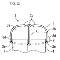
FIG. 12 , since the cross-sectional shapes of twoflow paths 3a and 3b of aheader tank 3 formed by a plurality ofplates header tank 3, stresses concentrate inbent parts 3c,joint parts 3d of theplates joint parts 3e of theplate 2 andheat exchange tubes 4, and the like parts. - On the other hand, it is conceivable that sufficient pressure-tightness is assured by making the configuration such that, as shown in
FIG. 13 , aheader tank 6 is formed by twotank tubes - In this case, however, in order to return the refrigerant flowing into one
tank tube 7 from theheat exchange tube 4 to theother tank 8, areturn flow path 9 must be provided additionally, which leads to an increase in the number of parts, an increase in size of heat exchanger caused by the provision of thereturn flow path 9, and the like. In the configuration shown inFIG. 12 , the refrigerant is returned from the one flow path 3a to theother flow path 3b through holes formed in apartition wall 5 provided between theflow paths 3a and 3b, so that the above-described problems do not occur. - The present invention has been accomplished to solve the above-described technical problems, and accordingly an object thereof is to provide a heat exchanger having sufficient pressure-tightness without an increase in the number of parts and an increase in size of the heat exchanger.
- The heat exchanger of the present invention, which has been accomplished to achieve the above object, comprises a plurality of heat exchange tubes arranged in parallel with each other, a fin provided between the heat exchange tubes adjacent to each other, a first header tank connected to one end side of the plurality of heat exchange tubes, and a second header tank connected to the other end side of the plurality of heat exchange tubes. The first header tank and the second header tank each comprises a header plate into which the end parts of the plurality of heat exchange tubes are inserted, a tank plate facing the header plate, and an intermediate plate held between the header plate and the tank plate. The header plate, the tank plate, and the intermediate plate are joined to each other in end parts on both sides and a middle part in the width direction thereof, whereby between the header plate and the tank plate, refrigerant flow paths are formed on one side and the other side with the middle part being held therebetween. The intermediate plate crosses the refrigerant flow paths in the direction in which the end parts and the middle part are connected in the refrigerant flow paths, and the intermediate plate has an elastically deformed part which allows the end parts and the middle part to be displaced relatively in the direction where they move closer to or away from each other.
- By the intermediate plate that is provided between the header plate and the tank plate and crosses the refrigerant flow paths, the first header tank and the second header tank are reinforced. Further, the intermediate plate has the elastically deformed part. When the end part on each side and the middle part in the width direction, in which the header plate, the tank plate, and the intermediate plate are joined to each other, are displaced relatively in the direction where they move closer to or away from each other, the elastic deformation of the elastically deformed part can allow this displacement.
- The intermediate plate can have a concave part, which is continuous in the longitudinal direction of the intermediate plate, on at least one surface thereof. In this case, at least one of the header plate and the tank plate has a convex part having a shape corresponding to the concave part. It is preferable that the concave part of the intermediate plate be formed in the middle part in the width direction of the intermediate plate, the convex part of the at least one of the header plate and the tank plate be formed in a portion facing the concave part, and the concave part and the convex part be joined to each other. By the use of such a configuration, the joint strength between the header plate and the intermediate plate and between the tank plate and the intermediate plate can be enhanced.
- At least one of the intermediate plate of the first header tank and the intermediate plate of the second header tank may be characterized by a communicating port which is continuous to both sides with the middle part being straddled, and the refrigerant flow path on one side and the refrigerant flow path on the other side communicate with each other via the communicating port with the middle part being held therebetween. Thereby, the refrigerant can be returned from the refrigerant flow path on one side to the refrigerant flow path on the other side with the middle part being held therebetween.
- At this time, the width in the header tank longitudinal direction of the communicating port in the intermediate plate is preferably not narrower than 2.0 mm and not wider than 3.8 mm. This can provide an optimal width capable of assuring the flowability of refrigerant and preventing the performance of heat exchanger from decreasing while assuring the strength of the intermediate plate.
- The plate thicknesses of the header plate, the tank plate, and the intermediate plate each are preferably not smaller than 1.0 mm and not larger than 2.0 mm. Thereby, the strength can be assured while the increase in weight of the whole of heat exchanger is restrained. In addition, an optimal plate thickness capable of restraining the increase in pressure loss and preventing the performance of heat exchanger from decreasing without decreasing the volumes in the first and second header tanks than necessary can be provided.
- Further, a vehicle air conditioning apparatus provided with any of the above-described heat exchangers can be configured. Thereby, the size of the whole of an air conditioning unit can be inhibited from increasing and the performance of the heat exchanger can be prevented from decreasing, so that a compact and high-performance air conditioning apparatus can be provided.
- According to the present invention, by the intermediate plate that is provided between the header plate and the tank plate and crosses the refrigerant flow paths, the first header tank and the second header tank are reinforced. Further, the intermediate plate has the elastically deformed part. When the end part on each side and the middle part in the width direction, in which the header plate, the tank plate, and the intermediate plate are joined to each other, are displaced relatively in the direction where they move closer to or away from each other, the elastically deformed part can allow this displacement. Thereby, stresses are prevented from concentrating in the joint portion of the header plate, the tank plate, and the intermediate plate, and the like portions, so that the strength performance of the first header tank and the second header tank can be improved. As a result, a heat exchanger having sufficient pressure-tightness can be configured without an increase in the number of parts and an increase in the size of the heat exchanger.
-
- [
FIG. 1] FIG. 1 is a perspective view showing a general configuration of a heat exchanger in accordance with an embodiment of the present invention. - [
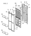
FIG. 2] FIG. 2 is an exploded perspective view showing a configuration of one header tank. - [
FIG. 3] FIG. 3 is a perspective transparent view of one header tank. - [
FIG. 4] FIG. 4 is a sectional view of a header tank. - [
FIG. 5] FIG. 5A is a sectional view showing a configuration of an intermediate plate provided in a header tank, andFIG. 5B is a perspective sectional view showing the same. - [
FIG. 6] FIG. 6 is an exploded perspective view showing a configuration of the other header tank. - [
FIG. 7] FIG. 7 is a perspective transparent view of the other header tank. - [
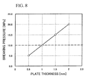
FIG. 8] FIG. 8 is a graph showing the relationship between plate thicknesses of a header plate, a tank plate, and an intermediate plate of the present embodiment and breaking pressure. - [
FIG. 9] FIG. 9 is a graph showing the relationship between slit width of a communicating slit in an intermediate plate of the present embodiment and breaking pressure. - [
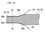
FIG. 10] FIG. 10 is an enlarged sectional view of a concave part provided on an intermediate plate. - [
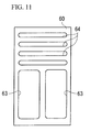
FIG. 11] FIG. 11 is a plan view showing another example of an intermediate plate. - [
FIG. 12] FIG. 12 is a sectional view showing one example of a conventional header tank. - [
FIG. 13] FIG. 13 is schematic views showing one example of a conventional heat exchanger provided with a return flow path on a header tank,FIG. 13A being a schematic view of the heat exchanger, andFIG. 13B being a schematic view showing a configuration near a return flow path. - The present invention will now be described in detail based on an embodiment shown in the accompanying drawings.
-
FIG. 1 is a perspective view showing a general configuration of aheat exchanger 10 in accordance with the embodiment of the present invention. - The
heat exchanger 10 includes a pair of header tanks, afirst header tank 20A and asecond header tank 20B, a plurality of flatheat exchange tubes 30 provided in parallel with each other between theseheader tanks corrugated fin 31 provided between theheat exchange tubes 30 adjacent to each other. - As shown in
FIGS. 1 to 4 , theheader tank 20A is formed by aheader plate 40 disposed on theheat exchange tube 30 side of theheader tank 20A, atank plate 50 disposed on the outside of theheat exchanger 10 so as to face theheader plate 40, and anintermediate plate 60 held between theheader plate 40 and thetank plate 50. - The
header plate 40 is configured so that the cross section thereof on a plane perpendicular to the axis line direction of theheader tank 20A substantially has a W shape,joint wall parts 41 for joining theheader plate 40 to thetank plate 50 are formed on both sides in the width direction thereof, and ajoint surface part 42 is formed in the middle portion in the width direction thereof. - The
joint wall part 41 is formed so as to rise toward the side facing thetank plate 50. - The
joint surface part 42 is formed in the direction (on the surface) such as to connect the both-sidejoint wall parts 41 to each other. - Between the both-side
joint wall parts 41 and thejoint surface part 42 of the middle portion, swellingparts 43 swelling toward the side opposite to the facingtank plate 50 are formed. To insert the end portions of theheat exchange tubes 30, the swellingpart 43 comprises a plurality ofslits 44 each having a shape corresponding to the cross-sectional shape of theheat exchange tube 30. - The
tank plate 50 is configured, like theheader plate 40, so that the cross section thereof on a plane perpendicular to the axis line direction of theheader tank 20A substantially has a W shape,joint wall parts 51 for joining thetank plate 50 to theheader plate 40 are formed on both sides in the width direction thereof, and ajoint surface part 52 is formed in the middle portion in the width direction thereof. - The
joint wall part 51 is formed so as to rise toward the side facing theheader plate 40. - The
joint surface part 52 is formed in the direction (on the surface) such as to connect the both-sidejoint wall parts 51 to each other. - Between the both-side
joint wall parts 51 and thejoint surface part 52 of the middle portion, swellingparts 53 swelling toward the side opposite to the facingheader plate 40 are formed. - The
intermediate plate 60 is of a substantially planar shape, and is configured so that bothend parts 61 and amiddle part 62 in the width direction thereof are held between theheader plate 40 and thetank plate 50. - The
intermediate plate 60 comprises a plurality ofopenings 63 between the bothend parts 61 and themiddle part 62 on one side extending from an intermediate portion in the longitudinal direction of theintermediate plate 60. - Also, in the
intermediate plate 60, communicating slits (communicating ports) 64 that are continuous to both sides with amiddle part 62 being straddled are formed on the other side extending from the intermediate portion in the longitudinal direction of theintermediate plate 60. - Between the
header plate 40 and thetank plate 50,closing plates header plate 40 and thetank plate 50, so that the space between theheader plate 40 and thetank plate 50 is dividedly closed. - The
header plate 40, thetank plate 50, theintermediate plate 60, and theclosing plates header tank 20A. - Since the
header plate 40 and thetank plate 50 are joined to each other via theintermediate plate 60 in thejoint wall parts joint surface parts header tank 20A has an eyeglasses-shaped cross section as the whole, andrefrigerant flow paths joint surface part 52 in the width direction. Theserefrigerant flow paths refrigerant flow paths 80A-1 and 80A-2 and intorefrigerant flow paths 80B-1 and 80B-2, respectively, by closingplate 70C. - As shown in
FIGS. 3 and5 , on the side on which the communicatingslits 64 are formed in theintermediate plate 60 with respect to theclosing plate 70C, therefrigerant flow path 80A-2 and therefrigerant flow path 80B-2 are caused to communicate with each other by the communicatingslits 64 between thejoint surface part 42 of theheader plate 40 and thejoint surface part 52 of thetank plate 50. - On the other hand, as shown in
FIGS. 1 ,6 and7 , theheader tank 20B is formed by theheader plate 40 disposed on theheat exchange tube 30 side of theheader tank 20B, thetank plate 50 disposed on the outside of theheat exchanger 10 so as to face theheader plate 40, and anintermediate plate 90 held between theheader plate 40 and thetank plate 50. - For the
header tank 20B, many constituent elements common to those of theheader tank 20A are used. In the explanation below, the same signs are applied to the constituent element common to that of theheader tank 20A, and the explanation thereof is sometimes omitted. - The
intermediate plate 90 is of a substantially planar shape, and is configured so that bothend parts 91 and amiddle part 92 in the width direction thereof are held between thejoint wall parts 41 in both-end portions of theheader plate 40 and thejoint wall parts 51 in both-end portions of thetank plate 50 and between thejoint surface part 42 in the middle portion of theheader plate 40 and thejoint surface part 52 in the middle portion of thetank plate 50. - The
intermediate plate 90 comprises a plurality ofopenings 93 along the longitudinal direction thereof. - Between the
header plate 40 and thetank plate 50,closing plates header plate 40 and thetank plate 50, so that the space between theheader plate 40 and thetank plate 50 is dividedly closed. - The
header plate 40, thetank plate 50, theintermediate plate 90, and theclosing plates header tank 20B. - As shown in
FIG. 4 , since theheader plate 40 and thetank plate 50 are joined to each other via theintermediate plate 90 in thejoint wall parts joint surface parts header tank 20B has an eyeglasses-shaped cross section as the whole, andrefrigerant flow paths joint surface part 52 in the width direction. Theserefrigerant flow paths - Herein, the plate thicknesses of the
header plate 40, thetank plate 50, and theintermediate plate -
FIG. 8 shows the analysis result, showing the relationship between plate thicknesses of theheader plate 40, thetank plate 50, and theintermediate plate - The breaking pressure is defined as an internal pressure applied on the
header tank header tank - In the case where the refrigerant design pressure is made about 3.0 MPa as one example of this embodiment, as shown in
FIG. 8 , a plate thickness that can withstand a breaking pressure of at least about 10.0 MPa is necessary. Therefore, it is found that the plate thickness of theintermediate plate FIG. 8 . Also, as the plate thickness of theintermediate plate heat exchanger 10 increases undesirably. In addition, if the plate thickness of theintermediate plate header tank heat exchanger 10. Therefore, considering the strength of theheader tank heat exchanger 10, it is important to make the plate thickness optimal. - From the above-described analysis result, in the case where the design pressure of this embodiment is about 3.0 MPa, the plate thickness of the
intermediate plate heat exchanger 10 can be provided. Therefore, each of the plate thicknesses of theheader plate 40, thetank plate 50, and theintermediate plate - Hereunder, the method for determining the plate thickness is explained. For example, in the case where the header tank is of a cylindrical shape, from the formula for stress on a thin-wall cylinder, the stress occurring in the circumferential direction in the header tank is determined by Expression (1).

in which σ is the occurring stress, P is the internal pressure, r is the inside radius of cylindrical shape, and t is the plate thickness. - The header tank is broken when the occurring stress σ exceeds the tensile strength σB, so that the relationship of Expression (2) holds.

- In the case where the inner periphery (circumference) of the cylindrical header tank is taken as L, and the inner area (cross-sectional area) thereof is taken as A, the occurring stress σ is expressed by Expression (3).
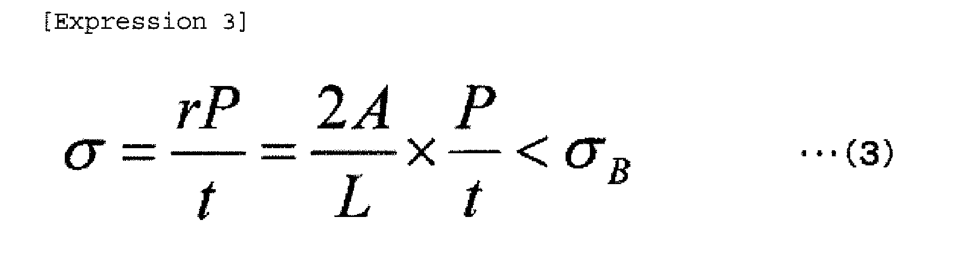
- Therefore, the plate thickness t in the case where the header tank is of a cylindrical shape is determined by Expression (4), and at least this plate thickness t is necessary to assure the strength.

- In this embodiment and the like in which the header tank is not of a cylindrical shape, a thickness not smaller than the plate thickness t determined by Expression (4) is necessary to consider the safety. Therefore, a factor α (a factor considering the safety) in Expression (5) is calculated based on the above-described analysis result of plate thickness and breaking pressure, and finally the optimal plate thickness t is determined by Expression (5).

-
FIG. 9 shows the analysis result, showing the relationship between slit width of the communicatingslit 64 in theintermediate plate 60 and breaking pressure. - In this embodiment, in the case where the
intermediate plate 60 has a plate thickness capable of withstanding a breaking pressure not lower than 10.0 MPa as described above, from the analysis result shown inFIG. 9 , as indicated by the solid line inFIG. 9 , it is preferable that the communicatingslit 64 have a slit width at most not wider than 3.8 mm to assure the strength of theintermediate plate 60. As the slit width of the communicatingslit 64 is decreased, the strength of theintermediate plate 60 is assured more. However, if the slit width is made too narrow, the refrigerant is less liable to pass through the communicatingslit 60, and the flowability of refrigerant is impaired, which may resultantly lead to the deterioration in performance of theheat exchanger 10. Upon this consideration, the slit width of the communicatingslit 64 is preferably made not narrower than 2.0 mm. If it is desired to further enhance the performance and safety (to assure the strength) of theheat exchanger 10, the slit width of the communicatingslit 64 is preferably made not narrower than 2.5 mm and not wider than 3.0 mm. - In the
heat exchanger 10 configured as described above, the refrigerant, which has flown into therefrigerant flow path 80A-1 of the oneheader tank 20A through aninflow port 22A, passes through theheat exchange tubes 30 and flows into therefrigerant flow path 80C of theother header tank 20B (refer toFIG. 1 ). At this time, in therefrigerant flow path 80C, the refrigerant flows into one side corresponding to therefrigerant flow path 80A-1. Then, in therefrigerant flow path 80C, the refrigerant moves to the other side, that is, the side corresponding to therefrigerant flow path 80A-2, and flows into therefrigerant flow path 80A-2 of the oneheader tank 20A after passing through theheat exchange tubes 30. - The refrigerant having flown into the
refrigerant flow path 80A-2, flows into therefrigerant flow path 80B-2 through the communicatingslits 64. Thereafter, the refrigerant flows into therefrigerant flow path 80D of theother header tank 20B from therefrigerant flow path 80B-2 after passing through the heat exchange tubes 30 (refer toFIG. 1 ). At this time, in therefrigerant flow path 80D, the refrigerant flows into one side corresponding to therefrigerant flow path 80B-2. Then, in therefrigerant flow path 80D, the refrigerant moves to the other side, that is, the side corresponding to therefrigerant flow path 80B-1, flows into therefrigerant flow path 80B-1 of the oneheader tank 20A after passing through theheat exchange tubes 30, and is discharged to the outside of theheat exchanger 10 through anoutflow port 22B. - In this embodiment, as shown in
FIGS. 4 and5A , theintermediate plate 60 comprises bent parts (elastically deformed parts) 100 between the central portion and the both-end portions in the width direction of theheader tank 20A. - In the
bent part 100, theintermediate plate 60 is bent into, for example, a crank shape between acentral portion side 100a and anend portion side 100b of theheader tank 20A, and is formed so that the heights of thecentral portion side 100a and theend portion side 100b are different from each other. Thebent part 100 is elastically deformed when themiddle part 62 and theend part 61 on each side are displaced relatively in the direction where they move closer to or away from each other. In this embodiment, atip end part 30a of theheat exchange tube 30 inserted through theslit 44 hits thecentral portion side 100a of theintermediate plate 60, and a clearance is formed between thetip end part 30a of theheat exchange tube 30 and theend portion side 100b. - Also, the configuration can be made such that the
tip end part 30a of theheat exchange tube 30 penetrates theintermediate plate tank plate 50 side rather than being located on theintermediate plate header tank heat exchange tubes 30. - Also, as shown in
FIGS. 5 and10 , in this embodiment, themiddle part intermediate plate concave parts intermediate plate joint surface part 42 of theheader plate 40 and thejoint surface part 52 of thetank plate 50 are formed withconvex parts concave parts concave parts convex parts header plate 40, thetank plate 50, and theintermediate plate 60 can be made longer, and therefore the joint strength can be improved. - In the above-described
heat exchanger 10, since theheader tank intermediate plate header plate 40 and thetank plate 50, theintermediate plate heat exchanger 10 capable of sufficiently accommodating a high-pressure refrigerant can be configured. Moreover, for theheader tanks header tanks header tank header plate 40 and thetank plate 50 need not be increased, so that the increase in size and weight of theheat exchanger 10 and the increase in material cost can be prevented. - In the
header tank 20A, theintermediate plate 60 comprises the communicatingslits 64, and therefrigerant flow paths 80A-2 and 80B-2 communicate with each other, and thereby a return flow path of refrigerant in theheader tank 20A is secured. Therefore, areturn flow path 9 as shown inFIG. 13 need not be provided additionally to secure the return flow path of refrigerant. In this respect as well, the increase in size and the like of theheat exchanger 10 can be avoided. - Also, since the
intermediate plate openings slits 64 are provided. - Since the
intermediate plate bent parts 100 between the central portion and the both end portions in the width direction of theheader tank bent parts 100 can prevent, for example, the stresses developed in brazing of theheader tank header plate 40, thetank plate 50, and theintermediate plate header tank - Further, since the
intermediate plate concave parts joint surface part 42 of theheader plate 40 and thejoint surface part 52 of thetank plate 50, respectively, the contact length of theheader plate 40, thetank plate 50, and theintermediate plate 60 can be made longer, and therefore the joint strength can be improved. - In the above-described embodiment, the specific shapes of the
header tanks header tanks openings slits 64 formed in theintermediate plates FIG. 11 , theopening 63 can be an elongated hole that is long in the longitudinal direction of theintermediate plate 60 so as not to hinder the flow of refrigerant as far as possible. - Also, the
bent part 100 may be formed into any shape and of any material if it is formed on theintermediate plate central portion side 100a and theend portion side 100b of theheader tank middle part 62 and theend part 61 on each side to be displaced relatively in the direction where they move closer to or away from each other. - Besides, the configurations described in this embodiment can be selected, or can be changed as appropriate to any other configurations without departing from the spirit and scope of the present invention.
- 10 ... heat exchanger, 20A ... header tank (first header tank), 20B ... header tank (second header tank), 30 ... heat exchange tube, 31 ... fin, 40 ... header plate, 41, 51 ... joint wall part, 42, 52 ... joint surface part, 43, 53 ... swelling part, 50 ... tank plate, 60, 90 ... intermediate plate, 61, 91 ... end part, 62, 92 ... middle part, 63, 93 ... opening, 64 ... communicating slit (communicating port), 70A, 70B, 70C ... closing plate, 80A, 80B, 80C, 80D ... refrigerant flow path, 95A, 95B ... concave part, 96A, 96B ... convex part, 100 ... bent part (elastically deformed part)
Claims (6)
- A heat exchanger comprising:a plurality of heat exchange tubes arranged in parallel with each other;fins provided between the heat exchange tubes adjacent to each other;a first header tank connected to one end side of the plurality of heat exchange tubes; anda second header tank connected to the other end side of the plurality of heat exchange tubes, whereinthe first header tank and the second header tank each comprises:a header plate into which the end parts of the plurality of heat exchange tubes are inserted;a tank plate facing the header plate; andan intermediate plate held between the header plate and the tank plate;the header plate, the tank plate, and the intermediate plate are joined to each other in end parts on both sides and a middle part in the width direction thereof, whereby between the header plate and the tank plate, refrigerant flow paths are formed on one side and the other side with the middle part being held therebetween; andthe intermediate plate crosses the refrigerant flow paths in the direction in which the end parts and the middle part are connected in the refrigerant flow paths, and the intermediate plate has an elastically deformed part which allows the end parts and the middle part to be displaced relatively in the direction where they move closer to or away from each other.
- The heat exchanger according to claim 1, wherein the intermediate plate has a concave part, which is continuous in the longitudinal direction of the intermediate plate, on at least one surface thereof;
at least one of the header plate and the tank plate has a convex part having a shape corresponding to the concave part;
the concave part of the intermediate plate is formed in the middle part in the width direction of the intermediate plate, and the convex part of the at least one of the header plate and the tank plate is formed in a portion facing the concave part; and
the concave part and the convex part are joined to each other. - The heat exchanger according to claim 1 or 2, wherein
at least one of the intermediate plate of the first header tank and the intermediate plate of the second header tank is provided with a communicating port which is continuous to both sides with the middle part being straddled; and
the refrigerant flow path on one side and the refrigerant flow path on the other side communicate with each other via the communicating port with the middle part being held therebetween. - The heat exchanger according to claim 1, wherein the plate thicknesses of the header plate, the tank plate, and the intermediate plate each are not smaller than 1.0 mm and not larger than 2.0 mm.
- The heat exchanger according to claim 3, wherein the width of the communicating port in the intermediate plate is not narrower than 2.0 mm and not wider than 3.8 mm.
- A vehicle air conditioning apparatus provided with the heat exchanger according to claim 1.
Applications Claiming Priority (2)
| Application Number | Priority Date | Filing Date | Title |
|---|---|---|---|
| JP2009239432A JP5737837B2 (en) | 2009-10-16 | 2009-10-16 | HEAT EXCHANGER AND VEHICLE AIR CONDITIONER INCLUDING THE SAME |
| PCT/JP2010/005089 WO2011045884A1 (en) | 2009-10-16 | 2010-08-17 | Heat exchanger and vehicle air conditioning apparatus provided with same |
Publications (3)
| Publication Number | Publication Date |
|---|---|
| EP2489974A1 true EP2489974A1 (en) | 2012-08-22 |
| EP2489974A4 EP2489974A4 (en) | 2018-04-11 |
| EP2489974B1 EP2489974B1 (en) | 2018-11-28 |
Family
ID=43875941
Family Applications (1)
| Application Number | Title | Priority Date | Filing Date |
|---|---|---|---|
| EP10823153.1A Not-in-force EP2489974B1 (en) | 2009-10-16 | 2010-08-17 | Heat exchanger and vehicle air conditioning apparatus provided with the same |
Country Status (4)
| Country | Link |
|---|---|
| US (1) | US20120204595A1 (en) |
| EP (1) | EP2489974B1 (en) |
| JP (1) | JP5737837B2 (en) |
| WO (1) | WO2011045884A1 (en) |
Cited By (3)
| Publication number | Priority date | Publication date | Assignee | Title |
|---|---|---|---|---|
| CN104019582A (en) * | 2013-02-28 | 2014-09-03 | 杭州三花研究院有限公司 | Parallel flow heat exchanger |
| CN104019583A (en) * | 2013-02-28 | 2014-09-03 | 杭州三花研究院有限公司 | Parallel flow heat exchanger |
| US11073345B2 (en) | 2018-10-31 | 2021-07-27 | Hanon Systems | Heat exchanger header with stiffening element |
Families Citing this family (18)
| Publication number | Priority date | Publication date | Assignee | Title |
|---|---|---|---|---|
| DE102006028017A1 (en) * | 2006-02-10 | 2007-08-16 | Behr Gmbh & Co. Kg | Heat exchanger, in particular with cold storage |
| JP5732592B2 (en) * | 2011-05-04 | 2015-06-10 | ハラ、ビステオン、クライメイト、コントロール コーポレーション | Cold storage heat exchanger |
| JP5809931B2 (en) * | 2011-11-02 | 2015-11-11 | 株式会社ケーヒン・サーマル・テクノロジー | Heat exchanger |
| JP6050978B2 (en) | 2012-07-23 | 2016-12-21 | 株式会社ケーヒン・サーマル・テクノロジー | Evaporator |
| JP2014055736A (en) * | 2012-09-13 | 2014-03-27 | Denso Corp | Heat exchanger |
| JP5749305B2 (en) * | 2013-09-03 | 2015-07-15 | 三桜工業株式会社 | Heat transfer tube, heat transfer tube manufacturing method, and heat exchanger |
| CN103541805B (en) * | 2013-11-12 | 2016-02-03 | 泰安鼎鑫冷却器有限公司 | A kind of automobile radiators with reinforced water chamber structure |
| EP2960609B1 (en) * | 2014-06-26 | 2022-10-05 | Valeo Autosystemy SP. Z.O.O. | Manifold, in particular for use in a cooler of a cooling system |
| JP6224564B2 (en) * | 2014-09-30 | 2017-11-01 | ダイキン工業株式会社 | Heat exchanger header |
| US9816766B2 (en) * | 2015-05-06 | 2017-11-14 | Hamilton Sundstrand Corporation | Two piece manifold |
| JP6978692B2 (en) * | 2019-05-10 | 2021-12-08 | ダイキン工業株式会社 | Heat exchanger and heat pump equipment |
| JP7037076B2 (en) * | 2019-05-10 | 2022-03-16 | ダイキン工業株式会社 | Manufacturing method of heat exchanger, heat pump device and heat exchanger |
| CN110118505A (en) * | 2019-06-19 | 2019-08-13 | 浙江银轮机械股份有限公司 | Flow collection pipe component and heat exchanger |
| JP7437418B2 (en) * | 2019-12-24 | 2024-02-22 | 東芝キヤリア株式会社 | Heat exchanger and refrigeration cycle equipment |
| WO2021130834A1 (en) * | 2019-12-24 | 2021-07-01 | 東芝キヤリア株式会社 | Heat exchanger and refrigeration cycle device |
| WO2021234962A1 (en) * | 2020-05-22 | 2021-11-25 | 三菱電機株式会社 | Heat exchanger |
| CN116157644B (en) * | 2020-09-23 | 2025-03-14 | 三菱电机株式会社 | Heat exchanger and air conditioner provided with same |
| JP7668903B2 (en) * | 2021-12-22 | 2025-04-25 | 三菱電機株式会社 | Heat exchanger and air conditioning device |
Family Cites Families (16)
| Publication number | Priority date | Publication date | Assignee | Title |
|---|---|---|---|---|
| US3307620A (en) * | 1965-11-24 | 1967-03-07 | Allie B Holmes | Engine cooling system with vacuum relief device therein |
| JPH10185463A (en) * | 1996-12-19 | 1998-07-14 | Sanden Corp | Heat-exchanger |
| JP3728534B2 (en) * | 2001-04-09 | 2005-12-21 | 漢拏空調株式会社 | Aluminum radiator |
| TW552382B (en) * | 2001-06-18 | 2003-09-11 | Showa Dendo Kk | Evaporator, manufacturing method of the same, header for evaporator and refrigeration system |
| JP2005532525A (en) * | 2002-07-05 | 2005-10-27 | ベール・ゲーエムベーハー・ウント・コ・カーゲー | Heat exchangers, especially evaporators for vehicle air conditioning units |
| JP4724433B2 (en) | 2004-03-17 | 2011-07-13 | 昭和電工株式会社 | Heat exchanger |
| JP2005326135A (en) * | 2004-04-12 | 2005-11-24 | Showa Denko Kk | Heat exchanger |
| JP2006189205A (en) * | 2005-01-06 | 2006-07-20 | Denso Corp | Heat exchanger |
| EP1848948B1 (en) * | 2005-02-18 | 2010-04-14 | ebm-papst St. Georgen GmbH & Co. KG | Heat exchanger |
| JP2007155268A (en) * | 2005-12-07 | 2007-06-21 | Denso Corp | Heat exchanger and refrigerant evaporator |
| US7448440B2 (en) * | 2005-12-14 | 2008-11-11 | Showa Denko K.K. | Heat exchanger |
| JP4724594B2 (en) * | 2006-04-28 | 2011-07-13 | 昭和電工株式会社 | Heat exchanger |
| US8371366B2 (en) * | 2006-10-03 | 2013-02-12 | Showa Denko K.K. | Heat exchanger |
| WO2008064219A1 (en) * | 2006-11-22 | 2008-05-29 | Johnson Controls Technology Company | Multichannel evaporator with flow mixing manifold |
| JP5114771B2 (en) * | 2007-05-29 | 2013-01-09 | 株式会社ケーヒン・サーマル・テクノロジー | Heat exchanger |
| JP4945399B2 (en) * | 2007-10-16 | 2012-06-06 | 昭和電工株式会社 | Heat exchanger |
-
2009
- 2009-10-16 JP JP2009239432A patent/JP5737837B2/en not_active Expired - Fee Related
-
2010
- 2010-08-17 EP EP10823153.1A patent/EP2489974B1/en not_active Not-in-force
- 2010-08-17 WO PCT/JP2010/005089 patent/WO2011045884A1/en not_active Ceased
- 2010-08-17 US US13/500,164 patent/US20120204595A1/en not_active Abandoned
Non-Patent Citations (1)
| Title |
|---|
| See references of WO2011045884A1 * |
Cited By (4)
| Publication number | Priority date | Publication date | Assignee | Title |
|---|---|---|---|---|
| CN104019582A (en) * | 2013-02-28 | 2014-09-03 | 杭州三花研究院有限公司 | Parallel flow heat exchanger |
| CN104019583A (en) * | 2013-02-28 | 2014-09-03 | 杭州三花研究院有限公司 | Parallel flow heat exchanger |
| CN104019583B (en) * | 2013-02-28 | 2018-09-11 | 杭州三花微通道换热器有限公司 | Parallel-flow heat exchanger |
| US11073345B2 (en) | 2018-10-31 | 2021-07-27 | Hanon Systems | Heat exchanger header with stiffening element |
Also Published As
| Publication number | Publication date |
|---|---|
| EP2489974B1 (en) | 2018-11-28 |
| WO2011045884A1 (en) | 2011-04-21 |
| JP5737837B2 (en) | 2015-06-17 |
| EP2489974A4 (en) | 2018-04-11 |
| US20120204595A1 (en) | 2012-08-16 |
| JP2011085343A (en) | 2011-04-28 |
Similar Documents
| Publication | Publication Date | Title |
|---|---|---|
| EP2489974B1 (en) | Heat exchanger and vehicle air conditioning apparatus provided with the same | |
| JP4724594B2 (en) | Heat exchanger | |
| US6216776B1 (en) | Heat exchanger | |
| JP4107051B2 (en) | Heat exchanger | |
| US10859327B2 (en) | Heat exchanger and manufacturing method for the same | |
| EP2981780B1 (en) | Plate heat exchanger and method for constructing multiple passes in the plate heat exchanger | |
| JP2010139088A (en) | Heat exchanger | |
| US7007745B2 (en) | Core structure of heat exchanger | |
| EP1564517B1 (en) | Tank for heat exchanger | |
| JP2007147172A (en) | Heat exchanger | |
| JP2015227737A (en) | Heat exchanger header | |
| KR102371382B1 (en) | A tube for heat exchanger | |
| JP2006194522A (en) | Heat exchanger | |
| JP4280133B2 (en) | Heat exchanger | |
| JP2010025447A (en) | Heat exchanger | |
| JP4533040B2 (en) | Connection structure between header tank of refrigerant and refrigerant distribution pipe | |
| JP2009198132A (en) | Tube for heat exchanger | |
| EP1724546A2 (en) | Heat Exchanger | |
| JP4852304B2 (en) | Heat exchanger | |
| JP2006017442A (en) | Heat exchanger | |
| JP2007147173A (en) | Heat exchanger and its manufacturing method | |
| JP4103762B2 (en) | Brazed flat tube | |
| JP2025167553A (en) | heat exchanger | |
| JP7485993B1 (en) | Heat exchanger | |
| JPH07103683A (en) | Heat exchanger |
Legal Events
| Date | Code | Title | Description |
|---|---|---|---|
| PUAI | Public reference made under article 153(3) epc to a published international application that has entered the european phase |
Free format text: ORIGINAL CODE: 0009012 |
|
| 17P | Request for examination filed |
Effective date: 20120330 |
|
| AK | Designated contracting states |
Kind code of ref document: A1 Designated state(s): AL AT BE BG CH CY CZ DE DK EE ES FI FR GB GR HR HU IE IS IT LI LT LU LV MC MK MT NL NO PL PT RO SE SI SK SM TR |
|
| DAX | Request for extension of the european patent (deleted) | ||
| RA4 | Supplementary search report drawn up and despatched (corrected) |
Effective date: 20180308 |
|
| RIC1 | Information provided on ipc code assigned before grant |
Ipc: F28F 9/02 20060101AFI20180303BHEP |
|
| GRAP | Despatch of communication of intention to grant a patent |
Free format text: ORIGINAL CODE: EPIDOSNIGR1 |
|
| STAA | Information on the status of an ep patent application or granted ep patent |
Free format text: STATUS: GRANT OF PATENT IS INTENDED |
|
| INTG | Intention to grant announced |
Effective date: 20180629 |
|
| GRAS | Grant fee paid |
Free format text: ORIGINAL CODE: EPIDOSNIGR3 |
|
| GRAA | (expected) grant |
Free format text: ORIGINAL CODE: 0009210 |
|
| STAA | Information on the status of an ep patent application or granted ep patent |
Free format text: STATUS: THE PATENT HAS BEEN GRANTED |
|
| AK | Designated contracting states |
Kind code of ref document: B1 Designated state(s): AL AT BE BG CH CY CZ DE DK EE ES FI FR GB GR HR HU IE IS IT LI LT LU LV MC MK MT NL NO PL PT RO SE SI SK SM TR |
|
| REG | Reference to a national code |
Ref country code: GB Ref legal event code: FG4D |
|
| REG | Reference to a national code |
Ref country code: CH Ref legal event code: EP |
|
| REG | Reference to a national code |
Ref country code: AT Ref legal event code: REF Ref document number: 1070722 Country of ref document: AT Kind code of ref document: T Effective date: 20181215 |
|
| REG | Reference to a national code |
Ref country code: DE Ref legal event code: R096 Ref document number: 602010055507 Country of ref document: DE |
|
| REG | Reference to a national code |
Ref country code: IE Ref legal event code: FG4D |
|
| REG | Reference to a national code |
Ref country code: NL Ref legal event code: MP Effective date: 20181128 |
|
| REG | Reference to a national code |
Ref country code: LT Ref legal event code: MG4D |
|
| REG | Reference to a national code |
Ref country code: AT Ref legal event code: MK05 Ref document number: 1070722 Country of ref document: AT Kind code of ref document: T Effective date: 20181128 |
|
| PG25 | Lapsed in a contracting state [announced via postgrant information from national office to epo] |
Ref country code: ES Free format text: LAPSE BECAUSE OF FAILURE TO SUBMIT A TRANSLATION OF THE DESCRIPTION OR TO PAY THE FEE WITHIN THE PRESCRIBED TIME-LIMIT Effective date: 20181128 Ref country code: AT Free format text: LAPSE BECAUSE OF FAILURE TO SUBMIT A TRANSLATION OF THE DESCRIPTION OR TO PAY THE FEE WITHIN THE PRESCRIBED TIME-LIMIT Effective date: 20181128 Ref country code: BG Free format text: LAPSE BECAUSE OF FAILURE TO SUBMIT A TRANSLATION OF THE DESCRIPTION OR TO PAY THE FEE WITHIN THE PRESCRIBED TIME-LIMIT Effective date: 20190228 Ref country code: NO Free format text: LAPSE BECAUSE OF FAILURE TO SUBMIT A TRANSLATION OF THE DESCRIPTION OR TO PAY THE FEE WITHIN THE PRESCRIBED TIME-LIMIT Effective date: 20190228 Ref country code: FI Free format text: LAPSE BECAUSE OF FAILURE TO SUBMIT A TRANSLATION OF THE DESCRIPTION OR TO PAY THE FEE WITHIN THE PRESCRIBED TIME-LIMIT Effective date: 20181128 Ref country code: IS Free format text: LAPSE BECAUSE OF FAILURE TO SUBMIT A TRANSLATION OF THE DESCRIPTION OR TO PAY THE FEE WITHIN THE PRESCRIBED TIME-LIMIT Effective date: 20190328 Ref country code: LT Free format text: LAPSE BECAUSE OF FAILURE TO SUBMIT A TRANSLATION OF THE DESCRIPTION OR TO PAY THE FEE WITHIN THE PRESCRIBED TIME-LIMIT Effective date: 20181128 Ref country code: LV Free format text: LAPSE BECAUSE OF FAILURE TO SUBMIT A TRANSLATION OF THE DESCRIPTION OR TO PAY THE FEE WITHIN THE PRESCRIBED TIME-LIMIT Effective date: 20181128 Ref country code: HR Free format text: LAPSE BECAUSE OF FAILURE TO SUBMIT A TRANSLATION OF THE DESCRIPTION OR TO PAY THE FEE WITHIN THE PRESCRIBED TIME-LIMIT Effective date: 20181128 |
|
| PG25 | Lapsed in a contracting state [announced via postgrant information from national office to epo] |
Ref country code: SE Free format text: LAPSE BECAUSE OF FAILURE TO SUBMIT A TRANSLATION OF THE DESCRIPTION OR TO PAY THE FEE WITHIN THE PRESCRIBED TIME-LIMIT Effective date: 20181128 Ref country code: AL Free format text: LAPSE BECAUSE OF FAILURE TO SUBMIT A TRANSLATION OF THE DESCRIPTION OR TO PAY THE FEE WITHIN THE PRESCRIBED TIME-LIMIT Effective date: 20181128 Ref country code: GR Free format text: LAPSE BECAUSE OF FAILURE TO SUBMIT A TRANSLATION OF THE DESCRIPTION OR TO PAY THE FEE WITHIN THE PRESCRIBED TIME-LIMIT Effective date: 20190301 Ref country code: PT Free format text: LAPSE BECAUSE OF FAILURE TO SUBMIT A TRANSLATION OF THE DESCRIPTION OR TO PAY THE FEE WITHIN THE PRESCRIBED TIME-LIMIT Effective date: 20190328 |
|
| PG25 | Lapsed in a contracting state [announced via postgrant information from national office to epo] |
Ref country code: NL Free format text: LAPSE BECAUSE OF FAILURE TO SUBMIT A TRANSLATION OF THE DESCRIPTION OR TO PAY THE FEE WITHIN THE PRESCRIBED TIME-LIMIT Effective date: 20181128 |
|
| PG25 | Lapsed in a contracting state [announced via postgrant information from national office to epo] |
Ref country code: CZ Free format text: LAPSE BECAUSE OF FAILURE TO SUBMIT A TRANSLATION OF THE DESCRIPTION OR TO PAY THE FEE WITHIN THE PRESCRIBED TIME-LIMIT Effective date: 20181128 Ref country code: PL Free format text: LAPSE BECAUSE OF FAILURE TO SUBMIT A TRANSLATION OF THE DESCRIPTION OR TO PAY THE FEE WITHIN THE PRESCRIBED TIME-LIMIT Effective date: 20181128 Ref country code: DK Free format text: LAPSE BECAUSE OF FAILURE TO SUBMIT A TRANSLATION OF THE DESCRIPTION OR TO PAY THE FEE WITHIN THE PRESCRIBED TIME-LIMIT Effective date: 20181128 Ref country code: IT Free format text: LAPSE BECAUSE OF FAILURE TO SUBMIT A TRANSLATION OF THE DESCRIPTION OR TO PAY THE FEE WITHIN THE PRESCRIBED TIME-LIMIT Effective date: 20181128 |
|
| REG | Reference to a national code |
Ref country code: DE Ref legal event code: R097 Ref document number: 602010055507 Country of ref document: DE |
|
| PG25 | Lapsed in a contracting state [announced via postgrant information from national office to epo] |
Ref country code: SK Free format text: LAPSE BECAUSE OF FAILURE TO SUBMIT A TRANSLATION OF THE DESCRIPTION OR TO PAY THE FEE WITHIN THE PRESCRIBED TIME-LIMIT Effective date: 20181128 Ref country code: RO Free format text: LAPSE BECAUSE OF FAILURE TO SUBMIT A TRANSLATION OF THE DESCRIPTION OR TO PAY THE FEE WITHIN THE PRESCRIBED TIME-LIMIT Effective date: 20181128 Ref country code: SM Free format text: LAPSE BECAUSE OF FAILURE TO SUBMIT A TRANSLATION OF THE DESCRIPTION OR TO PAY THE FEE WITHIN THE PRESCRIBED TIME-LIMIT Effective date: 20181128 Ref country code: EE Free format text: LAPSE BECAUSE OF FAILURE TO SUBMIT A TRANSLATION OF THE DESCRIPTION OR TO PAY THE FEE WITHIN THE PRESCRIBED TIME-LIMIT Effective date: 20181128 |
|
| PLBE | No opposition filed within time limit |
Free format text: ORIGINAL CODE: 0009261 |
|
| STAA | Information on the status of an ep patent application or granted ep patent |
Free format text: STATUS: NO OPPOSITION FILED WITHIN TIME LIMIT |
|
| PG25 | Lapsed in a contracting state [announced via postgrant information from national office to epo] |
Ref country code: SI Free format text: LAPSE BECAUSE OF FAILURE TO SUBMIT A TRANSLATION OF THE DESCRIPTION OR TO PAY THE FEE WITHIN THE PRESCRIBED TIME-LIMIT Effective date: 20181128 |
|
| PGFP | Annual fee paid to national office [announced via postgrant information from national office to epo] |
Ref country code: DE Payment date: 20190710 Year of fee payment: 10 |
|
| 26N | No opposition filed |
Effective date: 20190829 |
|
| PG25 | Lapsed in a contracting state [announced via postgrant information from national office to epo] |
Ref country code: TR Free format text: LAPSE BECAUSE OF FAILURE TO SUBMIT A TRANSLATION OF THE DESCRIPTION OR TO PAY THE FEE WITHIN THE PRESCRIBED TIME-LIMIT Effective date: 20181128 |
|
| PG25 | Lapsed in a contracting state [announced via postgrant information from national office to epo] |
Ref country code: LI Free format text: LAPSE BECAUSE OF NON-PAYMENT OF DUE FEES Effective date: 20190831 Ref country code: LU Free format text: LAPSE BECAUSE OF NON-PAYMENT OF DUE FEES Effective date: 20190817 Ref country code: MC Free format text: LAPSE BECAUSE OF FAILURE TO SUBMIT A TRANSLATION OF THE DESCRIPTION OR TO PAY THE FEE WITHIN THE PRESCRIBED TIME-LIMIT Effective date: 20181128 Ref country code: CH Free format text: LAPSE BECAUSE OF NON-PAYMENT OF DUE FEES Effective date: 20190831 |
|
| REG | Reference to a national code |
Ref country code: BE Ref legal event code: MM Effective date: 20190831 |
|
| PG25 | Lapsed in a contracting state [announced via postgrant information from national office to epo] |
Ref country code: IE Free format text: LAPSE BECAUSE OF NON-PAYMENT OF DUE FEES Effective date: 20190817 |
|
| PG25 | Lapsed in a contracting state [announced via postgrant information from national office to epo] |
Ref country code: BE Free format text: LAPSE BECAUSE OF NON-PAYMENT OF DUE FEES Effective date: 20190831 |
|
| REG | Reference to a national code |
Ref country code: DE Ref legal event code: R119 Ref document number: 602010055507 Country of ref document: DE |
|
| PG25 | Lapsed in a contracting state [announced via postgrant information from national office to epo] |
Ref country code: CY Free format text: LAPSE BECAUSE OF FAILURE TO SUBMIT A TRANSLATION OF THE DESCRIPTION OR TO PAY THE FEE WITHIN THE PRESCRIBED TIME-LIMIT Effective date: 20181128 |
|
| PG25 | Lapsed in a contracting state [announced via postgrant information from national office to epo] |
Ref country code: MT Free format text: LAPSE BECAUSE OF FAILURE TO SUBMIT A TRANSLATION OF THE DESCRIPTION OR TO PAY THE FEE WITHIN THE PRESCRIBED TIME-LIMIT Effective date: 20181128 Ref country code: HU Free format text: LAPSE BECAUSE OF FAILURE TO SUBMIT A TRANSLATION OF THE DESCRIPTION OR TO PAY THE FEE WITHIN THE PRESCRIBED TIME-LIMIT; INVALID AB INITIO Effective date: 20100817 Ref country code: DE Free format text: LAPSE BECAUSE OF NON-PAYMENT OF DUE FEES Effective date: 20210302 |
|
| PG25 | Lapsed in a contracting state [announced via postgrant information from national office to epo] |
Ref country code: MK Free format text: LAPSE BECAUSE OF FAILURE TO SUBMIT A TRANSLATION OF THE DESCRIPTION OR TO PAY THE FEE WITHIN THE PRESCRIBED TIME-LIMIT Effective date: 20181128 |
|
| PGFP | Annual fee paid to national office [announced via postgrant information from national office to epo] |
Ref country code: GB Payment date: 20230629 Year of fee payment: 14 |
|
| PGFP | Annual fee paid to national office [announced via postgrant information from national office to epo] |
Ref country code: FR Payment date: 20230703 Year of fee payment: 14 |
|
| GBPC | Gb: european patent ceased through non-payment of renewal fee |
Effective date: 20240817 |
|
| PG25 | Lapsed in a contracting state [announced via postgrant information from national office to epo] |
Ref country code: GB Free format text: LAPSE BECAUSE OF NON-PAYMENT OF DUE FEES Effective date: 20240817 |
|
| PG25 | Lapsed in a contracting state [announced via postgrant information from national office to epo] |
Ref country code: FR Free format text: LAPSE BECAUSE OF NON-PAYMENT OF DUE FEES Effective date: 20240831 |