EP2489893A1 - Power-transmission shaft and assembly - Google Patents
Power-transmission shaft and assembly Download PDFInfo
- Publication number
- EP2489893A1 EP2489893A1 EP10823287A EP10823287A EP2489893A1 EP 2489893 A1 EP2489893 A1 EP 2489893A1 EP 10823287 A EP10823287 A EP 10823287A EP 10823287 A EP10823287 A EP 10823287A EP 2489893 A1 EP2489893 A1 EP 2489893A1
- Authority
- EP
- European Patent Office
- Prior art keywords
- power transmission
- transmission shaft
- boot
- diameter
- spline
- Prior art date
- Legal status (The legal status is an assumption and is not a legal conclusion. Google has not performed a legal analysis and makes no representation as to the accuracy of the status listed.)
- Withdrawn
Links
Images


Classifications
-
- F—MECHANICAL ENGINEERING; LIGHTING; HEATING; WEAPONS; BLASTING
- F16—ENGINEERING ELEMENTS AND UNITS; GENERAL MEASURES FOR PRODUCING AND MAINTAINING EFFECTIVE FUNCTIONING OF MACHINES OR INSTALLATIONS; THERMAL INSULATION IN GENERAL
- F16D—COUPLINGS FOR TRANSMITTING ROTATION; CLUTCHES; BRAKES
- F16D1/00—Couplings for rigidly connecting two coaxial shafts or other movable machine elements
- F16D1/10—Quick-acting couplings in which the parts are connected by simply bringing them together axially
- F16D1/108—Quick-acting couplings in which the parts are connected by simply bringing them together axially having retaining means rotating with the coupling and acting by interengaging parts, i.e. positive coupling
- F16D1/116—Quick-acting couplings in which the parts are connected by simply bringing them together axially having retaining means rotating with the coupling and acting by interengaging parts, i.e. positive coupling the interengaging parts including a continuous or interrupted circumferential groove in the surface of one of the coupling parts
-
- F—MECHANICAL ENGINEERING; LIGHTING; HEATING; WEAPONS; BLASTING
- F16—ENGINEERING ELEMENTS AND UNITS; GENERAL MEASURES FOR PRODUCING AND MAINTAINING EFFECTIVE FUNCTIONING OF MACHINES OR INSTALLATIONS; THERMAL INSULATION IN GENERAL
- F16D—COUPLINGS FOR TRANSMITTING ROTATION; CLUTCHES; BRAKES
- F16D1/00—Couplings for rigidly connecting two coaxial shafts or other movable machine elements
- F16D1/10—Quick-acting couplings in which the parts are connected by simply bringing them together axially
- F16D2001/103—Quick-acting couplings in which the parts are connected by simply bringing them together axially the torque is transmitted via splined connections
-
- F—MECHANICAL ENGINEERING; LIGHTING; HEATING; WEAPONS; BLASTING
- F16—ENGINEERING ELEMENTS AND UNITS; GENERAL MEASURES FOR PRODUCING AND MAINTAINING EFFECTIVE FUNCTIONING OF MACHINES OR INSTALLATIONS; THERMAL INSULATION IN GENERAL
- F16D—COUPLINGS FOR TRANSMITTING ROTATION; CLUTCHES; BRAKES
- F16D3/00—Yielding couplings, i.e. with means permitting movement between the connected parts during the drive
- F16D3/16—Universal joints in which flexibility is produced by means of pivots or sliding or rolling connecting parts
- F16D3/20—Universal joints in which flexibility is produced by means of pivots or sliding or rolling connecting parts one coupling part entering a sleeve of the other coupling part and connected thereto by sliding or rolling members
- F16D3/22—Universal joints in which flexibility is produced by means of pivots or sliding or rolling connecting parts one coupling part entering a sleeve of the other coupling part and connected thereto by sliding or rolling members the rolling members being balls, rollers, or the like, guided in grooves or sockets in both coupling parts
- F16D3/223—Universal joints in which flexibility is produced by means of pivots or sliding or rolling connecting parts one coupling part entering a sleeve of the other coupling part and connected thereto by sliding or rolling members the rolling members being balls, rollers, or the like, guided in grooves or sockets in both coupling parts the rolling members being guided in grooves in both coupling parts
- F16D2003/22313—Details of the inner part of the core or means for attachment of the core on the shaft
Definitions
- the present invention relates to a power transmission shaft (shaft) to be used in a constant velocity universal joint and the like used in a power transmission system for automobiles and various industrial machines, and to an assembly unit.
- a shaft S1 to be coupled to a constant velocity universal joint generally has an end portion provided with a male spline 1 as illustrated in FIG. 4 , and a boot mount portion 2 is formed at a position apart from the male spline 1 by a predetermined dimension.
- the boot mount portion 2 is provided with a circumferential boot groove 3, and both opening portions of the boot groove 3 are provided with circumferential linear protrusions 4 and 5. Further, a small diameter portion 6 is provided between the boot mount portion 2 and the male spline 1. The small diameter portion 6 is provided so that the shaft S1 is prevented from interfering with an outer joint member of the constant velocity universal joint when the constant velocity universal joint forms an operating angle. An engagement large diameter portion 7, which is to be engaged with a female spline of an inner race 11 serving as an inner joint member of the constant velocity universal joint as described below, is provided between the small diameter portion 6 and the male spline 1.
- a tapered portion 8 is provided between the engagement large diameter portion 7 and the small diameter portion 6, and a tapered portion 9 is provided between the small diameter portion 6 and the boot mount portion 2. Further, a circumferential groove 10 is provided in an end portion (counter boot-mount-portion side) of the male spline 1.
- the shaft S1 is configured such that, when a maximum outer diameter of the male spline 1 is denoted by D11, an outer dimension of the engagement large diameter portion 7 is denoted by D12, an outer dimension of the small diameter portion 6 is denoted by D13, and a maximum outer dimension of the boot mount portion 2 (outer dimensions of the circumferential linear protrusions 4 and 5) is denoted by D14, a relationship D13 ⁇ D11 ⁇ D12 ⁇ D14 is established.
- the shaft S1 configured as described above is united, by fit-insertion, with the inner race 11 serving as the inner joint member of the constant velocity universal joint.
- the inner race 11 is provided with track grooves 13 circumferentially arranged at a predetermined pitch in an outer surface 12 thereof. Further, an inner surface of a hole portion 14 of the inner race 11 is provided with a female spline 15.
- the end portion of the shaft S1 is fit-inserted into the hole portion 14 of the inner race 11 in an arrow A direction.
- the male spline 1 of the end portion of the shaft S1 and the female spline 15 of the inner race 11 are fitted to each other.
- the fit-insertion of the shaft S1 is continued until the engagement large diameter portion 7 is engaged with a terminal end (one rim) of the female spline 15 of the inner race 11.
- the shaft S1 is fit-inserted into the hole portion 14 of the inner race 11 under a state in which a stopper ring 16 is fitted to the circumferential groove 10.
- the stopper ring 16 is pressed by the female spline 15 so as to radially shrink.
- the stopper ring 16 radially expands, and is engaged with a circumferential cutout portion 17 provided at an end portion of the hole portion 14 of the inner race 11 (end portion corresponding to a fit-insertion leading end portion of the shaft S1).
- the stopper ring 16 prevents the shaft S1 from dropping off in an arrow B direction, and the engagement large diameter portion 7 prevents the shaft S1 from being pushed in the arrow A direction. Therefore, axial displacement of the shaft S1 is avoided.
- the boot groove 3 provided with the above-mentioned circumferential linear protrusions 4 and 5 as illustrated in FIG. 4 is used so that, for securing sealing properties, the circumferential linear protrusions 4 and 5 bite into the resin boot at the time of mounting.
- Patent Literature 1 a constant velocity universal joint free from the circumferential linear protrusions 4 and 5 as illustrated in FIG. 4 (Patent Literature 1).
- an edge portion is provided at an opening portion of the boot groove by forming the boot groove into a predetermined shape so that the edge portion bites into the boot when the boot is mounted.
- a raw material diameter of the shaft is determined by a balance with respect to a male spline diameter and a boot groove diameter.
- a maximum diameter portions of the conventional shaft S1 as illustrated in FIG. 4 has been outer diameters of the circumferential linear protrusions 4 and 5 or an outer diameter of the engagement large diameter portion 7.
- Patent Literature 1 JP 3977975 B
- the raw material diameter of the shaft S1 As the raw material diameter of the shaft becomes smaller, a material cost can be correspondingly saved, and hence cost reduction can be achieved.
- a diameter of a shoulder portion of the shaft (outer diameter of the engagement large diameter portion 7) becomes largest.
- the raw material diameter of the shaft S1 is determined by the diameters of the circumferential linear protrusions 4 and 5 of the boot groove 3 or the diameter of the engagement large diameter portion 7, and hence cannot be set to be equal to or smaller than those diameters.
- the raw material diameter becomes relatively larger, and hence cost reduction cannot be expected.
- the diameter of the engagement large diameter portion 7 is used as a reference.
- the raw material diameter becomes relatively larger, and hence cost reduction cannot be expected.
- a power transmission shaft (shaft) which can achieve cost reduction by reducing the raw material diameter, and thus reducing a material cost and a lathing cost, and to provide an assembly unit using the power transmission shaft.
- the outer diameter of the engagement large diameter portion and the outer diameter of the boot mount portion are set to be equal to the diameter of the raw material of the shaft to maintain the diameter of the raw material of the shaft.
- the outer diameter of the engagement large diameter portion is smaller than the outer diameter of the male spline provided at the end portion.
- the male spline is formed by a rolling process or a spline pressing process.
- An inner diameter of a linear recess of the male spline can be set to be smaller than a blank diameter before rolling or a blank diameter before pressing, and an outer diameter of a linear protrusion of the male spline can be set to be larger than the blank diameter before rolling or the blank diameter before pressing.
- the outer diameter of the male spline provided at the end portion can be set to be larger than the outer diameter of the engagement large diameter portion.
- a material for the power transmission shaft may include a medium carbon steel.
- male splines may be provided at both end portions of the power transmission shaft, and each of the male splines may be capable of fitting to a female spline of any one of a fixed type constant velocity universal joint and a plunging type constant velocity universal joint.
- a boot material for the boot to be mounted to the boot mount portion may include a resin and a rubber.
- the resin include an ester-based, an olefin-based, a urethane-based, an amide-based, or a styrene-based thermoplastic elastomer.
- the rubber include a chloroprene rubber.
- the present invention provides an assembly unit including: the power transmission shaft; and an inner joint member of a constant velocity universal joint, the assembly unit being formed by combining the power transmission shaft and the inner joint member with each other, in which the male spline provided at the end portion of the power transmission shaft is fitted to a female spline provided in an inner surface of a hole portion of the inner joint member.
- the female spline of the inner joint member include a relief portion provided at a position corresponding to a part between the male spline and the engagement large diameter portion.
- the power transmission shaft according to the present invention can achieve cost reduction by reducing the raw material diameter, and thus reducing a material cost and a lathing cost of the shaft.
- a shape of the power transmission shaft (shaft) as a whole is formed closer into a flat shape.
- an axial variation in depth of a heat-treated hardened layer is reduced at the time of heat treatment, and hence product quality is stabilized.
- a medium carbon steel can be used, and hence it is unnecessary to use special materials.
- the power transmission shaft can be stably provided at low cost.
- the male spline can be fitted to the female spline of any one of the fixed type constant velocity universal joint and the plunging type constant velocity universal joint, the power transmission shaft is excellent in versatility.
- the boot to be used may be made of a resin or rubber.
- the power transmission shaft is applicable to boots made of various materials.
- the assembly unit according to the present invention uses the power transmission shaft.
- the material cost and the lathing cost can be saved, with the result that cost reduction can be achieved.
- the relief portion is provided to the inner joint member, further weight reduction can be achieved.
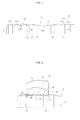
- FIG. 1 illustrates a power transmission shaft (shaft) according to the present invention.
- the shaft S is fixed by fit-insertion to an inner race 41 serving as an inner joint member of a constant velocity universal joint, and has an end portion provided with a male spline 31.
- a boot mount portion 32 is formed at a position apart from the male spline 31 by a predetermined dimension.
- a medium carbon steel is employed as a material for the shaft S.
- a carbon steel is an alloy of iron and carbon.
- a carbon steel with a carbon content of approximately 0.3 [mass%] or less is called a low carbon steel
- a carbon steel with a carbon content of approximately 0.3 [mass%] to 0.7 [mass%] is called the medium carbon steel
- a carbon steel with a carbon content of approximately 0.7 [mass%] or more is called a high carbon steel.
- the boot mount portion 32 is provided with a circumferential boot groove 33.
- the boot groove 33 in this case is free from a conventional circumferential linear protrusion.
- a groove bottom of the boot groove 33 is formed of a spline-side tapered portion 33a, a counter-spline-side circular arc portion 33c, and a straight portion 33b provided between the tapered portion 33a and the circular arc portion 33c.
- an edge portion is formed on the counter spline side of the boot groove 33.
- a small diameter portion 36 is provided between the boot mount portion 32 and the male spline 31.
- the small diameter portion 36 is provided so that the shaft S is prevented from interfering with an outer joint member of the constant velocity universal joint when the constant velocity universal joint forms an operating angle.
- An engagement large diameter portion 37 is provided between the small diameter portion 36 and the male spline 31.
- a tapered portion 38 is provided between the engagement large diameter portion 37 and the small diameter portion 36
- a tapered portion 39 is provided between the small diameter portion 36 and the boot mount portion 32.
- a circumferential groove 40 is provided in an end portion (counter boot-mount-portion side) of the male spline 31.
- the male spline 31 is formed by a rolling process or a spline pressing process.
- An inner diameter of a linear recess 31a of the male spline 31 can be set to be smaller than a blank diameter before rolling or a blank diameter before pressing, and an outer diameter of a linear protrusion 31b of the male spline 31 can be set to be larger than the blank diameter before rolling or the blank diameter before pressing.
- the maximum outer diameter of the male spline 31 can be set to be larger than the outer diameters of the engagement large diameter portion 37 and the boot mount portion 32.
- the inner race 41 serving as the inner joint member of the constant velocity universal joint, along which the shaft S is fit-inserted, is provided with track grooves 43 circumferentially arranged at a predetermined pitch in an outer surface 42 thereof. Further, an inner surface of a hole portion 44 of the inner race 41 is provided with a female spline 45.
- the end portion of the shaft S is fit-inserted into the hole portion 44 of the inner race 41 in an arrow A direction.
- the male spline 31 of the end portion of the shaft S is fitted to the female spline 45 of the inner race 41.
- the fit-insertion of the shaft S is continued until the engagement large diameter portion 37 is engaged with one tapered rim 45a of the female spline 45 of the inner race 41.
- a rim 37a on the inner-race hole portion side of the engagement large diameter portion 37 abuts against the tapered rim 45a.
- the shaft S is fit-inserted into the hole portion 44 of the inner race 41 under a state in which a stopper ring 46 is fitted to the circumferential groove 40.
- the stopper ring 46 is pressed by the female spline 45 so as to radially shrink.
- the stopper ring 46 Under a state in which the engagement large diameter portion 37 is engaged with the terminal end of the female spline 45 of the inner race 41, the stopper ring 46 radially expands, and is engaged with (fitted to) a circumferential cutout portion 47 provided at an end portion of the hole portion 44 of the inner race 41 (end portion corresponding to a fit-insertion leading end portion of the shaft S).
- the stopper ring 46 prevents the shaft S from dropping off in an arrow B direction, and the engagement large diameter portion 37 prevents the shaft S from being pushed in the arrow A direction. Therefore, axial displacement of the shaft S is avoided.
- an opposite end portion (not shown) of the shaft S is also provided with the male spline 31, the boot mount portion 32, and the like as illustrated in FIG. 1 .
- a boot material for the boot (not shown) to be mounted to the boot mount portion 32 may include a resin and rubber.
- the resin include an ester-based, an olefin-based, a urethane-based, an amide-based, or a styrene-based thermoplastic elastomer.
- the rubber include a chloroprene rubber.
- the outer diameters of the engagement large diameter portion 37 and the boot mount portion 32 are set to be equal to the diameter of the raw material of the shaft to maintain the diameter of the raw material of the shaft.
- the outer diameter of the engagement large diameter portion 37 is smaller than the outer diameter of the male spline 31 at the end portion.
- a diameter of a maximum diameter part (engagement large diameter portion) of the rawmaterial can be reduced.
- a diameter of the raw material can be set to be smaller than that of a conventional raw material, and hence lathing amounts of the boot groove and the male spline can be saved.
- a shape of the power transmission shaft (shaft) as a whole is formed closer into a flat shape.
- thermosetting treatment an axial variation in depth of a heat-treated hardened layer is reduced at the time of heat treatment, and hence product quality is stabilized.
- a medium carbon steel can be used, and hence it is unnecessary to use special materials. As a result, the power transmission shaft can be stably provided at low cost.
- the male spline 31 of the shaft (power transmission shaft) S can be fitted to a female spline of any one of a fixed type constant velocity universal joint and a plunging type constant velocity universal joint.
- the power transmission shaft S is excellent in versatility.
- the boot to be used may be made of a resin or rubber.
- the shaft S is applicable to boots made of various materials.
- the assembly unit according to the present invention uses the power transmission shaft.
- a material cost and a lathing cost can be saved, with the result that cost reduction can be achieved.
- FIG. 3 illustrates a modification of the inner race 41.
- the female spline 45 specifically, a linear protrusion 50 of the female spline 45 is provided with a relief portion (cutout portion) 56 at a position corresponding to a part (small diameter portion) 55 between the male spline 31 and the large diameter portion 37.
- the relief portion 56 can be formed in this way.
- FIG. 3 Other structural details of the assembly unit illustrated in FIG. 3 are the same as those of the above-mentioned assembly unit illustrated in FIG. 2 .
- the same components as those in FIG. 2 are denoted by the same reference symbols as in FIG. 2 , and description thereof is omitted. Therefore, the assembly unit illustrated in FIG. 3 also has the same functions and advantages as those of the assembly unit illustrated in FIG. 2 .
- the relief portion 56 is provided to the inner race 41, and hence further weight reduction can be achieved.
- any one of the fixed type constant velocity universal joint and the plunging type constant velocity universal joint may be employed as the constant velocity universal joint.
- the fixed type constant velocity universal joint may include various ones of a Rzeppa type and an undercut free type
- the plunging type constant velocity universal joint may include various ones of a double offset type, a tripod type, and a cross groove type.
- the power transmission shaft (shaft) may be solid or hollow.
- the medium carbon steel is employed as the material for the power transmission shaft (shaft), but the power transmission shaft (shaft) may be made of a low carbon steel or a high carbon steel. That is, such a shaft is generally made of a steel, but the shaft may be a made of a composite material such as an alloy and carbon. Further, it is preferred to perform thermosetting treatment on the surface of the shaft. As thermosetting treatment, there may be employed various heat treatments such as induction hardening and carburizing-and-quenching.
- the induction hardening refers to a quenching method in which a part required to be quenched is inserted into a coil carrying a high-frequency current, and which applies a principle that, with an electromagnetic induction action, Joule heat is generated to heat a conductive body.
- the carburizing-and-quenching refers to a method of causing carbon to intrude/spread from a surface of a low carbon material and then performing quenching of the material.
- Thepowertransmissionshaft (shaft) isused, for example, for a constant velocity universal joint to be used in a power transmission system for automobiles and various industrial machines.
- the power transmission shaft may be used as an assembly unit formed by being combined with a constant velocity universal joint.
Landscapes
- Engineering & Computer Science (AREA)
- General Engineering & Computer Science (AREA)
- Mechanical Engineering (AREA)
- Shafts, Cranks, Connecting Bars, And Related Bearings (AREA)
- Sealing Devices (AREA)
Abstract
Provided are a power transmission shaft (shaft) which can achieve cost reduction by reducing a raw material diameter, and thus reducing a material cost and a lathing cost, and an assembly unit using the power transmission shaft. The power transmission shaft includes: a male spline (31) provided at an end portion of the power transmission shaft; an engagement large diameter portion (37) for preventing the power transmission shaft from being pushed in an axial direction of the power transmission shaft under a state in which the male spline (31) is fitted to a female spline (45) of another member; and a boot groove (33) for mounting a boot. When an outer dimension of the engagement large diameter portion (37) is denoted by D2, a maximum outer dimension of the male spline (45) is denoted by D1, and an outer dimension of a boot mount portion (32) provided with the boot groove (33) is denoted by D4, relationships D2<D1 and D2=D4 are established. An outer diameter of the engagement large diameter portion (37) and an outer diameter of the boot mount portion (32) are set to be equal to the diameter of the raw material of the power transmission shaft to maintain the diameter of the raw material of the power transmission shaft.
Description
- The present invention relates to a power transmission shaft (shaft) to be used in a constant velocity universal joint and the like used in a power transmission system for automobiles and various industrial machines, and to an assembly unit.
- A shaft S1 to be coupled to a constant velocity universal joint generally has an end portion provided with a
male spline 1 as illustrated inFIG. 4 , and aboot mount portion 2 is formed at a position apart from themale spline 1 by a predetermined dimension. - The
boot mount portion 2 is provided with acircumferential boot groove 3, and both opening portions of theboot groove 3 are provided with circumferentiallinear protrusions small diameter portion 6 is provided between theboot mount portion 2 and themale spline 1. Thesmall diameter portion 6 is provided so that the shaft S1 is prevented from interfering with an outer joint member of the constant velocity universal joint when the constant velocity universal joint forms an operating angle. An engagementlarge diameter portion 7, which is to be engaged with a female spline of aninner race 11 serving as an inner joint member of the constant velocity universal joint as described below, is provided between thesmall diameter portion 6 and themale spline 1. Note that, atapered portion 8 is provided between the engagementlarge diameter portion 7 and thesmall diameter portion 6, and atapered portion 9 is provided between thesmall diameter portion 6 and theboot mount portion 2. Further, acircumferential groove 10 is provided in an end portion (counter boot-mount-portion side) of themale spline 1. - The shaft S1 is configured such that, when a maximum outer diameter of the
male spline 1 is denoted by D11, an outer dimension of the engagementlarge diameter portion 7 is denoted by D12, an outer dimension of thesmall diameter portion 6 is denoted by D13, and a maximum outer dimension of the boot mount portion 2 (outer dimensions of the circumferentiallinear protrusions 4 and 5) is denoted by D14, a relationship D13<D11<D12<D14 is established. - As illustrated in
FIG. 5 , the shaft S1 configured as described above is united, by fit-insertion, with theinner race 11 serving as the inner joint member of the constant velocity universal joint. Theinner race 11 is provided withtrack grooves 13 circumferentially arranged at a predetermined pitch in anouter surface 12 thereof. Further, an inner surface of ahole portion 14 of theinner race 11 is provided with afemale spline 15. - In this case, the end portion of the shaft S1 is fit-inserted into the
hole portion 14 of theinner race 11 in an arrow A direction. With this fit-insertion, themale spline 1 of the end portion of the shaft S1 and thefemale spline 15 of theinner race 11 are fitted to each other. The fit-insertion of the shaft S1 is continued until the engagementlarge diameter portion 7 is engaged with a terminal end (one rim) of thefemale spline 15 of theinner race 11. - Further, the shaft S1 is fit-inserted into the
hole portion 14 of theinner race 11 under a state in which astopper ring 16 is fitted to thecircumferential groove 10. During the fit-insertion, thestopper ring 16 is pressed by thefemale spline 15 so as to radially shrink. Under a state in which the engagementlarge diameter portion 7 is engaged with the terminal end of thefemale spline 15 of theinner race 11, thestopper ring 16 radially expands, and is engaged with acircumferential cutout portion 17 provided at an end portion of thehole portion 14 of the inner race 11 (end portion corresponding to a fit-insertion leading end portion of the shaft S1). - Thus, the
stopper ring 16 prevents the shaft S1 from dropping off in an arrow B direction, and the engagementlarge diameter portion 7 prevents the shaft S1 from being pushed in the arrow A direction. Therefore, axial displacement of the shaft S1 is avoided. - In a case of using resin boots that are widely used in recent years because resistance to rotational expansion, durability, and the like, the
boot groove 3 provided with the above-mentioned circumferentiallinear protrusions FIG. 4 is used so that, for securing sealing properties, the circumferentiallinear protrusions linear protrusions FIG. 4 (Patent Literature 1). In this case, an edge portion is provided at an opening portion of the boot groove by forming the boot groove into a predetermined shape so that the edge portion bites into the boot when the boot is mounted. - In the case of forming the shaft S1, a raw material diameter of the shaft is determined by a balance with respect to a male spline diameter and a boot groove diameter. A maximum diameter portions of the conventional shaft S1 as illustrated in
FIG. 4 has been outer diameters of the circumferentiallinear protrusions large diameter portion 7. - Patent Literature 1:
JP 3977975 B - With regard to cost of the shaft S1, as the raw material diameter of the shaft becomes smaller, a material cost can be correspondingly saved, and hence cost reduction can be achieved. However, in the case of the conventional shaft shape as illustrated in
FIG. 4 , when the diameters of the circumferentiallinear protrusions boot groove 3 or a diameter of theboot groove 3 can be set to be small, a diameter of a shoulder portion of the shaft (outer diameter of the engagement large diameter portion 7) becomes largest. In other words, in this case, the raw material diameter of the shaft S1 is determined by the diameters of the circumferentiallinear protrusions boot groove 3 or the diameter of the engagementlarge diameter portion 7, and hence cannot be set to be equal to or smaller than those diameters. As a result, the raw material diameter becomes relatively larger, and hence cost reduction cannot be expected. Further, also in the case where the circumferentiallinear protrusions large diameter portion 7 is used as a reference. Thus, also in this case, the raw material diameter becomes relatively larger, and hence cost reduction cannot be expected. - In view of the above-mentioned circumstances, it is an object of the present invention to provide a power transmission shaft (shaft) which can achieve cost reduction by reducing the raw material diameter, and thus reducing a material cost and a lathing cost, and to provide an assembly unit using the power transmission shaft.
- The present invention provides a power transmission shaft including: a male spline provided at an end portion of the power transmission shaft; an engagement large diameter portion for preventing the power transmission shaft from being pushed in an axial direction of the power transmission shaft under a state in which the male spline is fitted to a female spline of another member; and a boot groove for mounting a boot, in which, when an outer dimension of the engagement large diameter portion is denoted by D2, a maximum outer dimension of the male spline is denoted by D1, and an outer dimension of a boot mount portion provided with the boot groove is denoted by D4, relationships D2<D1 and D2=D4 are established, and in which an outer diameter of the engagement large diameter portion and an outer diameter of the boot mount portion are set to be equal to a diameter of a raw material of the power transmission shaft to maintain the diameter of the raw material of the power transmission shaft.
- According to the power transmission shaft of the present invention, the outer diameter of the engagement large diameter portion and the outer diameter of the boot mount portion are set to be equal to the diameter of the raw material of the shaft to maintain the diameter of the raw material of the shaft. In addition, the outer diameter of the engagement large diameter portion is smaller than the outer diameter of the male spline provided at the end portion. Thus, in comparison with a conventional shaft having a male spline of the same diameter, a diameter of a maximum diameter part (engagement large diameter portion) of the raw material can be reduced. In other words, a diameter of the raw material can be set to be smaller than that of a conventional raw material, and hence lathing amounts of the boot groove and the male spline can be saved. The male spline is formed by a rolling process or a spline pressing process. An inner diameter of a linear recess of the male spline can be set to be smaller than a blank diameter before rolling or a blank diameter before pressing, and an outer diameter of a linear protrusion of the male spline can be set to be larger than the blank diameter before rolling or the blank diameter before pressing. Thus, the outer diameter of the male spline provided at the end portion can be set to be larger than the outer diameter of the engagement large diameter portion.
- A material for the power transmission shaft may include a medium carbon steel. Further, male splines may be provided at both end portions of the power transmission shaft, and each of the male splines may be capable of fitting to a female spline of any one of a fixed type constant velocity universal joint and a plunging type constant velocity universal joint.
- A boot material for the boot to be mounted to the boot mount portion may include a resin and a rubber. Examples of the resin include an ester-based, an olefin-based, a urethane-based, an amide-based, or a styrene-based thermoplastic elastomer. Further, examples of the rubber include a chloroprene rubber.
- Further, the present invention provides an assembly unit including: the power transmission shaft; and an inner joint member of a constant velocity universal joint, the assembly unit being formed by combining the power transmission shaft and the inner joint member with each other, in which the male spline provided at the end portion of the power transmission shaft is fitted to a female spline provided in an inner surface of a hole portion of the inner joint member. In this case, it is preferred that the female spline of the inner joint member include a relief portion provided at a position corresponding to a part between the male spline and the engagement large diameter portion.
- The power transmission shaft according to the present invention can achieve cost reduction by reducing the raw material diameter, and thus reducing a material cost and a lathing cost of the shaft. A shape of the power transmission shaft (shaft) as a whole is formed closer into a flat shape. Thus, in a case of performing thermosetting treatment, an axial variation in depth of a heat-treated hardened layer is reduced at the time of heat treatment, and hence product quality is stabilized. Further, also in terms of the material, a medium carbon steel can be used, and hence it is unnecessary to use special materials. As a result, the power transmission shaft can be stably provided at low cost. When the male spline can be fitted to the female spline of any one of the fixed type constant velocity universal joint and the plunging type constant velocity universal joint, the power transmission shaft is excellent in versatility.
- The boot to be used may be made of a resin or rubber. Thus, the power transmission shaft is applicable to boots made of various materials.
- The assembly unit according to the present invention uses the power transmission shaft. Thus, the material cost and the lathing cost can be saved, with the result that cost reduction can be achieved. Further, when the relief portion is provided to the inner joint member, further weight reduction can be achieved.
-
- [
FIG. 1 ] A side view of a power transmission shaft according to an embodiment of the present invention. - [
FIG. 2 ] A sectional view of an assembly unit using the power transmission shaft illustrated inFIG. 1 . - [
FIG. 3 ] A sectional view illustrating a modification of the assembly unit. - [
FIG. 4 ] A side view of a conventional power transmission shaft. - [
FIG. 5 ] A sectional view of an assembly unit using the conventional power transmission shaft. - In the following, description is made of an embodiment of the present invention with reference to
FIGS. 1 to 3 . -
FIG. 1 illustrates a power transmission shaft (shaft) according to the present invention. As illustrated inFIG. 2 , the shaft S is fixed by fit-insertion to aninner race 41 serving as an inner joint member of a constant velocity universal joint, and has an end portion provided with amale spline 31. In addition, aboot mount portion 32 is formed at a position apart from themale spline 31 by a predetermined dimension. A medium carbon steel is employed as a material for the shaft S. A carbon steel is an alloy of iron and carbon. Of carbon steels, a carbon steel with a carbon content of approximately 0.3 [mass%] or less is called a low carbon steel, a carbon steel with a carbon content of approximately 0.3 [mass%] to 0.7 [mass%] is called the medium carbon steel, and a carbon steel with a carbon content of approximately 0.7 [mass%] or more is called a high carbon steel. - The
boot mount portion 32 is provided with acircumferential boot groove 33. Theboot groove 33 in this case is free from a conventional circumferential linear protrusion. Further, a groove bottom of theboot groove 33 is formed of a spline-sidetapered portion 33a, a counter-spline-sidecircular arc portion 33c, and astraight portion 33b provided between thetapered portion 33a and thecircular arc portion 33c. Thus, an edge portion is formed on the counter spline side of theboot groove 33. When a boot (not shown) is mounted to theboot mount portion 32, the edge portion bites into the boot, and hence a stable mounting state can be maintained. - Further, a
small diameter portion 36 is provided between theboot mount portion 32 and themale spline 31. Thesmall diameter portion 36 is provided so that the shaft S is prevented from interfering with an outer joint member of the constant velocity universal joint when the constant velocity universal joint forms an operating angle. An engagementlarge diameter portion 37 is provided between thesmall diameter portion 36 and themale spline 31. Note that, a taperedportion 38 is provided between the engagementlarge diameter portion 37 and thesmall diameter portion 36, and a taperedportion 39 is provided between thesmall diameter portion 36 and theboot mount portion 32. Further, acircumferential groove 40 is provided in an end portion (counter boot-mount-portion side) of themale spline 31. - In this case, when a maximum outer diameter of the
male spline 31 is denoted by D1, an outer dimension of the engagementlarge diameter portion 37 is denoted by D2, an outer dimension of thesmall diameter portion 36 is denoted by D3, and a maximum outer dimension of theboot mount portion 32 is denoted by D4, relationships D2<D1 and D2=D4 are established. In other words, outer diameters of the engagementlarge diameter portion 37 and theboot mount portion 32 are set to be equal to a diameter of a raw material of the shaft to maintain the diameter of the raw material of the shaft. Note that, a relationship D3<D2 is established. - The
male spline 31 is formed by a rolling process or a spline pressing process. An inner diameter of alinear recess 31a of themale spline 31 can be set to be smaller than a blank diameter before rolling or a blank diameter before pressing, and an outer diameter of alinear protrusion 31b of themale spline 31 can be set to be larger than the blank diameter before rolling or the blank diameter before pressing. Thus, even when the raw material diameter is smaller than the maximum outer diameter of themale spline 31, when themale spline 31 is formed, the maximum outer diameter of themale spline 31 can be set to be larger than the outer diameters of the engagementlarge diameter portion 37 and theboot mount portion 32. - By the way, as illustrated in
FIG. 2 , theinner race 41 serving as the inner joint member of the constant velocity universal joint, along which the shaft S is fit-inserted, is provided withtrack grooves 43 circumferentially arranged at a predetermined pitch in anouter surface 42 thereof. Further, an inner surface of ahole portion 44 of theinner race 41 is provided with afemale spline 45. - In this case, the end portion of the shaft S is fit-inserted into the
hole portion 44 of theinner race 41 in an arrow A direction. With this fit-insertion, themale spline 31 of the end portion of the shaft S is fitted to thefemale spline 45 of theinner race 41. The fit-insertion of the shaft S is continued until the engagementlarge diameter portion 37 is engaged with one taperedrim 45a of thefemale spline 45 of theinner race 41. In other words, arim 37a on the inner-race hole portion side of the engagementlarge diameter portion 37 abuts against thetapered rim 45a. - Further, the shaft S is fit-inserted into the
hole portion 44 of theinner race 41 under a state in which astopper ring 46 is fitted to thecircumferential groove 40. During the fit-insertion, thestopper ring 46 is pressed by thefemale spline 45 so as to radially shrink. Under a state in which the engagementlarge diameter portion 37 is engaged with the terminal end of thefemale spline 45 of theinner race 41, thestopper ring 46 radially expands, and is engaged with (fitted to) acircumferential cutout portion 47 provided at an end portion of thehole portion 44 of the inner race 41 (end portion corresponding to a fit-insertion leading end portion of the shaft S). In this way, an assembly unit, which is obtained by combining the power transmission shaft S and theinner race 41 of the constant velocity universal joint with each other, is formed. - Thus, the
stopper ring 46 prevents the shaft S from dropping off in an arrow B direction, and the engagementlarge diameter portion 37 prevents the shaft S from being pushed in the arrow A direction. Therefore, axial displacement of the shaft S is avoided. - Further, an opposite end portion (not shown) of the shaft S is also provided with the
male spline 31, theboot mount portion 32, and the like as illustrated inFIG. 1 . - A boot material for the boot (not shown) to be mounted to the
boot mount portion 32 may include a resin and rubber. Examples of the resin include an ester-based, an olefin-based, a urethane-based, an amide-based, or a styrene-based thermoplastic elastomer. Further, examples of the rubber include a chloroprene rubber. - In the present invention, the outer diameters of the engagement
large diameter portion 37 and theboot mount portion 32 are set to be equal to the diameter of the raw material of the shaft to maintain the diameter of the raw material of the shaft. In addition, the outer diameter of the engagementlarge diameter portion 37 is smaller than the outer diameter of themale spline 31 at the end portion. Thus, in comparison with a conventional shaft having a male spline of the same diameter, a diameter of a maximum diameter part (engagement large diameter portion) of the rawmaterial can be reduced. In other words, a diameter of the raw material can be set to be smaller than that of a conventional raw material, and hence lathing amounts of the boot groove and the male spline can be saved. With this, a material cost and a lathing cost of the shaft can be saved, with the result that cost reduction can be achieved. A shape of the power transmission shaft (shaft) as a whole is formed closer into a flat shape. Thus, in a case of performing thermosetting treatment, an axial variation in depth of a heat-treated hardened layer is reduced at the time of heat treatment, and hence product quality is stabilized. Further, also in terms of the material, a medium carbon steel can be used, and hence it is unnecessary to use special materials. As a result, the power transmission shaft can be stably provided at low cost. - The
male spline 31 of the shaft (power transmission shaft) S can be fitted to a female spline of any one of a fixed type constant velocity universal joint and a plunging type constant velocity universal joint. Thus, the power transmission shaft S is excellent in versatility. - The boot to be used may be made of a resin or rubber. Thus, the shaft S is applicable to boots made of various materials.
- The assembly unit according to the present invention uses the power transmission shaft. Thus, a material cost and a lathing cost can be saved, with the result that cost reduction can be achieved.
- Next,
FIG. 3 illustrates a modification of theinner race 41. In this case, thefemale spline 45, specifically, alinear protrusion 50 of thefemale spline 45 is provided with a relief portion (cutout portion) 56 at a position corresponding to a part (small diameter portion) 55 between themale spline 31 and thelarge diameter portion 37. In other words, at the position corresponding to thepart 55, it is unnecessary to perform spline fitting, and hence therelief portion 56 can be formed in this way. - Other structural details of the assembly unit illustrated in
FIG. 3 are the same as those of the above-mentioned assembly unit illustrated inFIG. 2 . Thus, the same components as those inFIG. 2 are denoted by the same reference symbols as inFIG. 2 , and description thereof is omitted. Therefore, the assembly unit illustrated inFIG. 3 also has the same functions and advantages as those of the assembly unit illustrated inFIG. 2 . More advantageously, therelief portion 56 is provided to theinner race 41, and hence further weight reduction can be achieved. - Hereinabove, description is made of the embodiment of the present invention, but the present invention is not limited to the above-mentioned embodiment, and various modifications may be made thereto. For example, any one of the fixed type constant velocity universal joint and the plunging type constant velocity universal joint may be employed as the constant velocity universal joint. The fixed type constant velocity universal joint may include various ones of a Rzeppa type and an undercut free type, and the plunging type constant velocity universal joint may include various ones of a double offset type, a tripod type, and a cross groove type. Further, the power transmission shaft (shaft) may be solid or hollow.
- In the above-mentioned embodiment, the medium carbon steel is employed as the material for the power transmission shaft (shaft), but the power transmission shaft (shaft) may be made of a low carbon steel or a high carbon steel. That is, such a shaft is generally made of a steel, but the shaft may be a made of a composite material such as an alloy and carbon. Further, it is preferred to perform thermosetting treatment on the surface of the shaft. As thermosetting treatment, there may be employed various heat treatments such as induction hardening and carburizing-and-quenching. Here, the induction hardening refers to a quenching method in which a part required to be quenched is inserted into a coil carrying a high-frequency current, and which applies a principle that, with an electromagnetic induction action, Joule heat is generated to heat a conductive body. The carburizing-and-quenching refers to a method of causing carbon to intrude/spread from a surface of a low carbon material and then performing quenching of the material.
- Thepowertransmissionshaft (shaft) isused, for example, for a constant velocity universal joint to be used in a power transmission system for automobiles and various industrial machines. The power transmission shaft may be used as an assembly unit formed by being combined with a constant velocity universal joint.
-
- 31
- male spline
- 32
- boot mount portion
- 33
- boot groove
- 37
- engagement large diameter portion
- 45
- female spline
- 55
- part
- 56
- relief portion
Claims (8)
- A power transmission shaft, comprising:a male spline provided at an end portion of the power transmission shaft;an engagement large diameter portion for preventing the power transmission shaft from being pushed in an axial direction of the power transmission shaft under a state in which the male spline is fitted to a female spline of another member; anda boot groove for mounting a boot,wherein, when an outer dimension of the engagement large diameter portion is denoted by D2, a maximum outer dimension of the male spline is denoted by D1, and an outer dimension of a boot mount portion provided with the boot groove is denoted by D4, relationships D2<D1 and D2=D4 are established, andwherein an outer diameter of the engagement large diameter portion and an outer diameter of the boot mount portion are set to be equal to a diameter of a raw material of the power transmission shaft to maintain the diameter of the raw material of the power transmission shaft.
- A power transmission shaft according to claim 1, wherein a material for the power transmission shaft comprises a medium carbon steel.
- A power transmission shaft according to claim 1 or 2, wherein the male spline is finished by a rolling process or a pressing process.
- A power transmission shaft according to any one of claims 1 to 3, wherein the male spline comprises male splines provided at both end portions of the power transmission shaft, each of the male splines being capable of fitting to a female spline of any one of a fixed type constant velocity universal joint and a plunging type constant velocity universal joint.
- A power transmission shaft according to any one of claims 1 to 4, wherein a boot material for the boot to be mounted to the boot mount portion comprises a resin.
- A power transmission shaft according to any one of claims 1 to 4, wherein a boot material for the boot to be mounted to the boot mount portion comprises rubber.
- An assembly unit, comprising:the power transmission shaft according to any one of claims 1 to 6; andan inner joint member of a constant velocity universal joint, the assembly unit being formed by combining the power transmission shaft and the inner joint member with each other,wherein the male spline provided at the end portion of the power transmission shaft is fitted to a female spline provided in an inner surface of a hole portion of the inner joint member.
- An assembly unit according to claim 7, wherein the female spline of the inner joint member comprises a relief portion provided at a position corresponding to a part between the male spline and the engagement large diameter portion.
Applications Claiming Priority (2)
| Application Number | Priority Date | Filing Date | Title |
|---|---|---|---|
| JP2009236117A JP2011085152A (en) | 2009-10-13 | 2009-10-13 | Power transmission shaft, and assembly |
| PCT/JP2010/066876 WO2011046019A1 (en) | 2009-10-13 | 2010-09-29 | Power-transmission shaft and assembly |
Publications (1)
| Publication Number | Publication Date |
|---|---|
| EP2489893A1 true EP2489893A1 (en) | 2012-08-22 |
Family
ID=43876072
Family Applications (1)
| Application Number | Title | Priority Date | Filing Date |
|---|---|---|---|
| EP10823287A Withdrawn EP2489893A1 (en) | 2009-10-13 | 2010-09-29 | Power-transmission shaft and assembly |
Country Status (5)
| Country | Link |
|---|---|
| US (1) | US20120172137A1 (en) |
| EP (1) | EP2489893A1 (en) |
| JP (1) | JP2011085152A (en) |
| CN (1) | CN102575718A (en) |
| WO (1) | WO2011046019A1 (en) |
Families Citing this family (5)
| Publication number | Priority date | Publication date | Assignee | Title |
|---|---|---|---|---|
| EP2980433B1 (en) * | 2013-03-25 | 2019-08-21 | NTN Corporation | Power transmission shaft and spline-processing method |
| US9915291B2 (en) | 2013-07-30 | 2018-03-13 | Nsk Ltd. | Torque transmission shaft having universal joint yoke and method of manufacturing the same |
| US11125277B2 (en) | 2017-07-19 | 2021-09-21 | Zhejiang CFMOTO Power Co., Ltd. | Type of constant velocity universal joint with the spline slip structure |
| US11242896B2 (en) * | 2017-07-19 | 2022-02-08 | Zhejiang Cfmoto Power Co. Ltd. | Spline slip constant velocity joint |
| JP6533860B1 (en) * | 2018-12-04 | 2019-06-19 | 株式会社ショーワ | Propulsion shaft |
Family Cites Families (10)
| Publication number | Priority date | Publication date | Assignee | Title |
|---|---|---|---|---|
| DE3326990A1 (en) * | 1983-07-27 | 1985-02-07 | Dr.Ing.H.C. F. Porsche Ag, 7000 Stuttgart | DEVICE FOR ADJUSTING JOINT SHAFTS |
| WO2000005514A1 (en) * | 1998-07-22 | 2000-02-03 | Ntn Corporation | Power transmission mechanism |
| JP3977975B2 (en) | 2000-01-25 | 2007-09-19 | Ntn株式会社 | Constant velocity universal joint |
| JP2005146313A (en) * | 2003-11-12 | 2005-06-09 | Ntn Corp | Power transmission shaft |
| US7419433B2 (en) * | 2004-05-24 | 2008-09-02 | Ntn Corporation | ATV drive shaft and constant velocity joint |
| JP2005344746A (en) * | 2004-05-31 | 2005-12-15 | Toyoda Mach Works Ltd | Drive shaft |
| JP4979938B2 (en) * | 2005-12-26 | 2012-07-18 | Ntn株式会社 | Constant velocity universal joint and its inner member |
| JP2007232043A (en) * | 2006-02-28 | 2007-09-13 | Ntn Corp | Boot mounting structure |
| JP2007292170A (en) * | 2006-04-24 | 2007-11-08 | Ntn Corp | Power transmission shaft and its manufacturing method |
| EP2175177B1 (en) * | 2007-07-31 | 2015-11-04 | NTN Corporation | Boot fixing method |
-
2009
- 2009-10-13 JP JP2009236117A patent/JP2011085152A/en not_active Withdrawn
-
2010
- 2010-09-29 US US13/394,571 patent/US20120172137A1/en not_active Abandoned
- 2010-09-29 WO PCT/JP2010/066876 patent/WO2011046019A1/en not_active Ceased
- 2010-09-29 EP EP10823287A patent/EP2489893A1/en not_active Withdrawn
- 2010-09-29 CN CN201080046266XA patent/CN102575718A/en active Pending
Non-Patent Citations (1)
| Title |
|---|
| See references of WO2011046019A1 * |
Also Published As
| Publication number | Publication date |
|---|---|
| JP2011085152A (en) | 2011-04-28 |
| US20120172137A1 (en) | 2012-07-05 |
| WO2011046019A1 (en) | 2011-04-21 |
| CN102575718A (en) | 2012-07-11 |
Similar Documents
| Publication | Publication Date | Title |
|---|---|---|
| KR101510797B1 (en) | constant velocity universal joint | |
| US10086648B2 (en) | Bearing device for a wheel | |
| US10508692B2 (en) | Propeller shaft and propeller shaft production method | |
| US20120172137A1 (en) | Power-transmission shaft and assembly | |
| US9856906B2 (en) | Hollow shaft and constant velocity universal joint | |
| CN108394452B (en) | Assembly of shaft and yoke | |
| US20100195947A1 (en) | Bearing device for a wheel | |
| JP2008284919A (en) | Bearing device for wheel, method of assembling bearing device for wheel, assembly body, and method of assembling assembly body | |
| EP2202419B1 (en) | Fixed constant velocity universal joint | |
| US10962063B2 (en) | Fixed constant velocity universal joint | |
| JP2011231792A (en) | Sliding constant velocity universal joint, and ironing process method of outer joint member thereof | |
| CN109578450B (en) | Rotational drive force transmission mechanism | |
| JP2009121673A (en) | Constant speed universal joint | |
| EP1760347B1 (en) | Shaft for constant velocity universal joint | |
| WO2012128278A1 (en) | Bearing device for wheel and method of manufacturing same | |
| JP2007032760A (en) | Constant velocity universal joint and its inside member | |
| JP2009228813A (en) | Constant velocity universal joint | |
| CN1924377B (en) | Shaft for constant velocity universal joint | |
| JP2008207586A (en) | Wheel bearing device and its manufacturing method | |
| JP2009264535A (en) | Fixed type constant velocity universal joint | |
| JP2009255659A (en) | Bearing device for wheel | |
| JP2007211926A (en) | Inner member of constant velocity universal joint and its manufacturing method | |
| WO2024176892A1 (en) | Wheel bearing device | |
| JP2009228811A (en) | Constant velocity universal joint | |
| JP2010031910A (en) | Outside joint member of constant velocity universal joint and constant velocity universal joint |
Legal Events
| Date | Code | Title | Description |
|---|---|---|---|
| PUAI | Public reference made under article 153(3) epc to a published international application that has entered the european phase |
Free format text: ORIGINAL CODE: 0009012 |
|
| 17P | Request for examination filed |
Effective date: 20120511 |
|
| AK | Designated contracting states |
Kind code of ref document: A1 Designated state(s): AL AT BE BG CH CY CZ DE DK EE ES FI FR GB GR HR HU IE IS IT LI LT LU LV MC MK MT NL NO PL PT RO SE SI SK SM TR |
|
| STAA | Information on the status of an ep patent application or granted ep patent |
Free format text: STATUS: THE APPLICATION HAS BEEN WITHDRAWN |
|
| DAX | Request for extension of the european patent (deleted) | ||
| 18W | Application withdrawn |
Effective date: 20121228 |