EP2489873B1 - Blade pitch angle adjusting apparatus for a wind turbine - Google Patents
Blade pitch angle adjusting apparatus for a wind turbine Download PDFInfo
- Publication number
- EP2489873B1 EP2489873B1 EP11154655.2A EP11154655A EP2489873B1 EP 2489873 B1 EP2489873 B1 EP 2489873B1 EP 11154655 A EP11154655 A EP 11154655A EP 2489873 B1 EP2489873 B1 EP 2489873B1
- Authority
- EP
- European Patent Office
- Prior art keywords
- pitch
- brake
- maximum
- torque
- motor
- Prior art date
- Legal status (The legal status is an assumption and is not a legal conclusion. Google has not performed a legal analysis and makes no representation as to the accuracy of the status listed.)
- Active
Links
- 239000011295 pitch Substances 0.000 description 111
- 239000003638 chemical reducing agent Substances 0.000 description 1
- 210000003746 feather Anatomy 0.000 description 1
- 238000002955 isolation Methods 0.000 description 1
- 230000001360 synchronised effect Effects 0.000 description 1
Images
Classifications
-
- F—MECHANICAL ENGINEERING; LIGHTING; HEATING; WEAPONS; BLASTING
- F03—MACHINES OR ENGINES FOR LIQUIDS; WIND, SPRING, OR WEIGHT MOTORS; PRODUCING MECHANICAL POWER OR A REACTIVE PROPULSIVE THRUST, NOT OTHERWISE PROVIDED FOR
- F03D—WIND MOTORS
- F03D7/00—Controlling wind motors
- F03D7/02—Controlling wind motors the wind motors having rotation axis substantially parallel to the air flow entering the rotor
- F03D7/022—Adjusting aerodynamic properties of the blades
- F03D7/0224—Adjusting blade pitch
-
- F—MECHANICAL ENGINEERING; LIGHTING; HEATING; WEAPONS; BLASTING
- F05—INDEXING SCHEMES RELATING TO ENGINES OR PUMPS IN VARIOUS SUBCLASSES OF CLASSES F01-F04
- F05B—INDEXING SCHEME RELATING TO WIND, SPRING, WEIGHT, INERTIA OR LIKE MOTORS, TO MACHINES OR ENGINES FOR LIQUIDS COVERED BY SUBCLASSES F03B, F03D AND F03G
- F05B2240/00—Components
- F05B2240/40—Use of a multiplicity of similar components
-
- F—MECHANICAL ENGINEERING; LIGHTING; HEATING; WEAPONS; BLASTING
- F05—INDEXING SCHEMES RELATING TO ENGINES OR PUMPS IN VARIOUS SUBCLASSES OF CLASSES F01-F04
- F05B—INDEXING SCHEME RELATING TO WIND, SPRING, WEIGHT, INERTIA OR LIKE MOTORS, TO MACHINES OR ENGINES FOR LIQUIDS COVERED BY SUBCLASSES F03B, F03D AND F03G
- F05B2260/00—Function
- F05B2260/70—Adjusting of angle of incidence or attack of rotating blades
- F05B2260/79—Bearing, support or actuation arrangements therefor
-
- F—MECHANICAL ENGINEERING; LIGHTING; HEATING; WEAPONS; BLASTING
- F05—INDEXING SCHEMES RELATING TO ENGINES OR PUMPS IN VARIOUS SUBCLASSES OF CLASSES F01-F04
- F05B—INDEXING SCHEME RELATING TO WIND, SPRING, WEIGHT, INERTIA OR LIKE MOTORS, TO MACHINES OR ENGINES FOR LIQUIDS COVERED BY SUBCLASSES F03B, F03D AND F03G
- F05B2260/00—Function
- F05B2260/90—Braking
- F05B2260/903—Braking using electrical or magnetic forces
-
- Y—GENERAL TAGGING OF NEW TECHNOLOGICAL DEVELOPMENTS; GENERAL TAGGING OF CROSS-SECTIONAL TECHNOLOGIES SPANNING OVER SEVERAL SECTIONS OF THE IPC; TECHNICAL SUBJECTS COVERED BY FORMER USPC CROSS-REFERENCE ART COLLECTIONS [XRACs] AND DIGESTS
- Y02—TECHNOLOGIES OR APPLICATIONS FOR MITIGATION OR ADAPTATION AGAINST CLIMATE CHANGE
- Y02E—REDUCTION OF GREENHOUSE GAS [GHG] EMISSIONS, RELATED TO ENERGY GENERATION, TRANSMISSION OR DISTRIBUTION
- Y02E10/00—Energy generation through renewable energy sources
- Y02E10/70—Wind energy
- Y02E10/72—Wind turbines with rotation axis in wind direction
Definitions
- the present invention pertains to a wind turbine blade pitch angle adjusting apparatus for adjusting the pitch angle of a blade of a wind turbine, comprising an electric pitch motor able to output a maximum motor torque Tm, and a pitch brake assembly able to generate a maximum brake assembly torque Tb.
- Pitch control systems having blade pitch angle adjusting apparatuses are known from the state of the art.
- a pitch control system according to the prior art is known from the document WO 00/61942 .
- each rotor blade is pitched individually with a dedicated blade pitch angle adjusting apparatus, namely an electromechanical actuator.
- Each such actuator comprises an electric pitch motor, a reducer and an electromagnetic pitch brake.
- the pitch brake is in a braking condition.
- the pitch brake is released, and the pitch motor drives the blade in a rotary motion around its longitudinal axis.
- the pitch brake returns to its default braking condition and stops the rotating blade.
- Such a blade pitch angle adjusting apparatus has the drawback that the pitching of the blade is no longer possible when the pitch brake fails. When such a failure occurs, the pitch brake cannot be released and consequently the pitch motor operates against a closed brake. This can cause an overload to the motor's electric circuit and damage the motor. In any case, the pitch motor is unable to turn the blade. Accordingly, the wind turbine looses its pitching capability, can no longer adapt to varying wind conditions, and risks to be subjected to dangerously high loads caused by aerodynamic imbalances.
- a solution to this problem is to provide the blade pitch angle adjusting apparatus with a high power pitch motor that is able to overcome the braking force of the pitch brake in case of brake failure.
- this solution is not satisfying since it increases the size, cost and weight of the pitch motor.
- An object of the present invention is therefore to provide a blade pitch angle adjusting apparatus of small size, low weight and low cost that is able to adjust blade pitch even in case of pitch brake failure.
- a wind turbine blade pitch angle adjusting apparatus for adjusting the pitch angle of a blade of a wind turbine, comprising an electric pitch motor able to output a maximum motor torque Tm, and a pitch brake assembly able to generate a maximum brake assembly torque Tb, characterised in that the pitch brake assembly comprises a plurality of individual pitch brakes each able to generate a maximum individual brake torque Tsb, the maximum brake assembly torque Tb is the sum of all maximum individual brake torques Tsb, and the maximum motor torque Tm is higher than the maximum individual brake torque Tsb of any one of the pitch brakes.
- the pitch brake assembly By providing a pitch brake assembly with several individual pitch brakes, the total braking force and the risk of pitch brake failure are distributed over several brakes instead of one. If one of the individual pitch brakes fails the pitch motor only has to overcome the partial braking force of this individual pitch brake for pitching. Hence, the pitch motor can be kept smaller than in the prior art solution using a high power pitch motor.
- Document RU 2 354 845 C1 discloses a blade pitch angle adjusting apparatus which, instead of having an electric pitch motor, exploits the kinetic energy of the wind turbine for pitching.
- the apparatus of the invention has one or several of the following features, taken in isolation or in all technically possible combinations:
- the invention also relates to a wind turbine comprising a rotor, the rotor comprising a hub, at least one blade rotatably mounted on the hub about a pitch axis for adjusting the pitch angle of the blade, and a blade pitch angle adjusting apparatus for adjusting the pitch angle of the blade as defined above.
- a blade pitch angle adjusting apparatus 1 This apparatus is located in a rotor hub (not shown) of a wind turbine. One end 2 of the apparatus 1 is in meshing engagement with a ring gear 3. The ring gear 3 is fixed to the lower end of a rotor blade (not shown). The ring gear 3 and the rotor blade are rotatable with respect to the rotor hub about a pitch axis corresponding substantially to a longitudinal axis of the rotor blade.
- the blade pitch angle adjusting apparatus 1 comprises, from the figure's left to the right, a pinion 4, a reduction gear 5, a drive shaft 6, an electric pitch motor M, and a pitch brake assembly 7.
- Pitch motor M is able to output a maximum motor torque Tm.
- the drive shaft 6 is connected to the motor M so as to be driven by the motor M and has a driving end 9 and a braking end 10.
- the driving end 9 is connected to the reduction gear 5, which in turn is connected to the pinion 4.
- the pinion 4 is in meshing engagement with the ring gear 3.
- the pitch brake assembly 7 comprises two individual pitch brakes 11 and 12. If desired, the pitch brake assembly 7 could comprise more than two individual pitch brakes.
- the pitch brakes 11 and 12 surround the braking end 10 of the motor shaft 6 and are arranged next to each other. However, pitch brakes 11 and 12 may also be arranged between the pitch motor M and the reduction gear 5. Another possible arrangement is to have one of the pitch brakes between the pitch motor M and the reduction gear 5, while the other pitch brake is located at the braking end 10. The advantage of having a pitch brake between the motor M and the reduction gear 5 is that the rotor blade can be kept locked in position during a replacement of motor M.
- Pitch brakes 11, 12 are of the self-locking type, which means that, by default, pitch brakes 11, 12 are in a braking condition.
- Each pitch brake 11, 12 is a self contained brake unit with its own power supply. Accordingly, each pitch brake 11, 12 is able to function independently from the other. In particular, pitch brake 11 is able to operate even in case of failure of pitch brake 12 and vice versa.
- pitch brakes 11 and 12 are electromagnetic brakes. In another embodiment, not shown, the pitch brakes are hydraulic brakes.
- the blade pitch angle adjusting apparatus 1 also comprises means (not shown) for controlling the pitch brakes 11, 12 to behave as a single pitch brake.
- the pitch motor M and the pitch brakes 11, 12 are chosen such that Tb > Tm > Tsb.
- the blade pitch angle adjusting apparatus 1 operates in the following manner in order to adjust the pitch of the associated rotor blade:
- the pitch brake control means provides power to both individual brakes 11, 12 concurrently in order to release the pitch brake assembly 7.
- the pitch motor M is energised and drives the drive shaft 6.
- the pinion 4 rotates, which leads to a rotation of the ring gear 3 and the attached rotor blade.
- the pitch motor M stops and the pitch brake control means deactivates both individual brakes 11, 12 in order to brake the drive shaft 6 and hence the rotor blade.
- control means controls the pitch brakes 11, 12 in such a manner that they operate as a single pitch brake.
- the control means controls the pitch brakes 11, 12 in a synchronous manner.
- the pitch motor M thanks to its maximum motor torque Tm that is higher than the maximum individual brake torque Tsb, overcomes the failed individual brake's braking force and pitches the wind blade into the safe feather position in order to avoid damage to the wind turbine.
- the remaining pitch brake can be released to allow pitching the rotor blade. Meanwhile the rotor blade can be maintained reliably in the desired position upon deactivating the said remaining pitch brake 11, 12.
- the pitch motor M Since the likelihood of simultaneous failure of both independent brakes 11, 12 is negligible the pitch motor M only needs sufficient power to overcome the partial braking force of one failed individual brake. Accordingly, the pitch motor M can have a compact size without jeopardising the wind turbine's security.
Abstract
Description
- The present invention pertains to a wind turbine blade pitch angle adjusting apparatus for adjusting the pitch angle of a blade of a wind turbine, comprising an electric pitch motor able to output a maximum motor torque Tm, and a pitch brake assembly able to generate a maximum brake assembly torque Tb.
- Pitch control systems having blade pitch angle adjusting apparatuses are known from the state of the art.
- A pitch control system according to the prior art is known from the document
WO 00/61942 - In these systems, each rotor blade is pitched individually with a dedicated blade pitch angle adjusting apparatus, namely an electromechanical actuator. Each such actuator comprises an electric pitch motor, a reducer and an electromagnetic pitch brake.
- By default, the pitch brake is in a braking condition. In order to adjust the pitch angle, the pitch brake is released, and the pitch motor drives the blade in a rotary motion around its longitudinal axis. When reaching the desired pitch angle, the pitch brake returns to its default braking condition and stops the rotating blade.
- Such a blade pitch angle adjusting apparatus has the drawback that the pitching of the blade is no longer possible when the pitch brake fails. When such a failure occurs, the pitch brake cannot be released and consequently the pitch motor operates against a closed brake. This can cause an overload to the motor's electric circuit and damage the motor. In any case, the pitch motor is unable to turn the blade. Accordingly, the wind turbine looses its pitching capability, can no longer adapt to varying wind conditions, and risks to be subjected to dangerously high loads caused by aerodynamic imbalances.
- A solution to this problem is to provide the blade pitch angle adjusting apparatus with a high power pitch motor that is able to overcome the braking force of the pitch brake in case of brake failure. However, this solution is not satisfying since it increases the size, cost and weight of the pitch motor.
- An object of the present invention is therefore to provide a blade pitch angle adjusting apparatus of small size, low weight and low cost that is able to adjust blade pitch even in case of pitch brake failure.
- This object is achieved by a wind turbine blade pitch angle adjusting apparatus for adjusting the pitch angle of a blade of a wind turbine, comprising an electric pitch motor able to output a maximum motor torque Tm, and a pitch brake assembly able to generate a maximum brake assembly torque Tb, characterised in that the pitch brake assembly comprises a plurality of individual pitch brakes each able to generate a maximum individual brake torque Tsb, the maximum brake assembly torque Tb is the sum of all maximum individual brake torques Tsb, and the maximum motor torque Tm is higher than the maximum individual brake torque Tsb of any one of the pitch brakes.
- By providing a pitch brake assembly with several individual pitch brakes, the total braking force and the risk of pitch brake failure are distributed over several brakes instead of one. If one of the individual pitch brakes fails the pitch motor only has to overcome the partial braking force of this individual pitch brake for pitching. Hence, the pitch motor can be kept smaller than in the prior art solution using a high power pitch motor.
- Document
RU 2 354 845 C1 - According to preferred embodiments, the apparatus of the invention has one or several of the following features, taken in isolation or in all technically possible combinations:
- the maximum brake assembly torque Tb is higher than the maximum motor torque Tm;
- means for controlling the pitch brakes to brake jointly;
- each of the pitch brakes is a self contained brake unit with its own power supply;
- the pitch brake assembly consists of two pitch brakes;
- the maximum individual brake torque Tsb of each pitch brake is half the maximum brake assembly torque Tb of the pitch brake assembly;
- a drive shaft connected to the pitch motor and the pitch brake assembly in order to be driven by the pitch motor and braked by the pitch brake assembly;
- a reduction gear connected to the pitch motor.
- The invention also relates to a wind turbine comprising a rotor, the rotor comprising a hub, at least one blade rotatably mounted on the hub about a pitch axis for adjusting the pitch angle of the blade, and a blade pitch angle adjusting apparatus for adjusting the pitch angle of the blade as defined above.
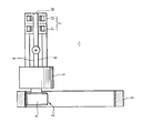
- The invention will be better understood when reading the following description of a non limiting example of the invention, with reference to the accompanying figure, which is a schematic side view of a blade pitch angle adjusting apparatus according to the invention.
- With reference to the figure, there is shown a blade pitch
angle adjusting apparatus 1. This apparatus is located in a rotor hub (not shown) of a wind turbine. One end 2 of theapparatus 1 is in meshing engagement with aring gear 3. Thering gear 3 is fixed to the lower end of a rotor blade (not shown). Thering gear 3 and the rotor blade are rotatable with respect to the rotor hub about a pitch axis corresponding substantially to a longitudinal axis of the rotor blade. - The blade pitch
angle adjusting apparatus 1 comprises, from the figure's left to the right, a pinion 4, a reduction gear 5, a drive shaft 6, an electric pitch motor M, and a pitch brake assembly 7. - Pitch motor M is able to output a maximum motor torque Tm.
- The drive shaft 6 is connected to the motor M so as to be driven by the motor M and has a driving
end 9 and a braking end 10. The drivingend 9 is connected to the reduction gear 5, which in turn is connected to the pinion 4. The pinion 4 is in meshing engagement with thering gear 3. - In the shown example, the pitch brake assembly 7 comprises two individual pitch brakes 11 and 12. If desired, the pitch brake assembly 7 could comprise more than two individual pitch brakes. In the shown example, the pitch brakes 11 and 12 surround the braking end 10 of the motor shaft 6 and are arranged next to each other. However, pitch brakes 11 and 12 may also be arranged between the pitch motor M and the reduction gear 5. Another possible arrangement is to have one of the pitch brakes between the pitch motor M and the reduction gear 5, while the other pitch brake is located at the braking end 10. The advantage of having a pitch brake between the motor M and the reduction gear 5 is that the rotor blade can be kept locked in position during a replacement of motor M.
- Pitch brakes 11, 12 are of the self-locking type, which means that, by default, pitch brakes 11, 12 are in a braking condition.
- Each pitch brake 11, 12 is a self contained brake unit with its own power supply. Accordingly, each pitch brake 11, 12 is able to function independently from the other. In particular, pitch brake 11 is able to operate even in case of failure of pitch brake 12 and vice versa. Preferably, pitch brakes 11 and 12 are electromagnetic brakes. In another embodiment, not shown, the pitch brakes are hydraulic brakes.
- The blade pitch
angle adjusting apparatus 1 also comprises means (not shown) for controlling the pitch brakes 11, 12 to behave as a single pitch brake. - Each pitch brake 11, 12 is able to generate a maximum individual brake torque Tsb (Tsb1 and Tsb2, respectively). Accordingly, the pitch brake assembly 7 is able to generate a maximum brake assembly torque Tb = Tsb1 + Tsb2. In the present example, Tsb1 = Tsb2 such that Tb = 2 * Tsb1 = 2 * Tsb2.
- In an alternative embodiment, Tsb1 = 2 * Tsb2 such that Tsb2 = Tb/3 and Tsb1 = 2 * Tb/3.
- The pitch motor M and the pitch brakes 11, 12 are chosen such that Tb > Tm > Tsb.
- The blade pitch
angle adjusting apparatus 1 operates in the following manner in order to adjust the pitch of the associated rotor blade: - Firstly, the pitch brake control means provides power to both individual brakes 11, 12 concurrently in order to release the pitch brake assembly 7. Then, the pitch motor M is energised and drives the drive shaft 6. Hence, via the reduction gear 5, the pinion 4 rotates, which leads to a rotation of the
ring gear 3 and the attached rotor blade. When the desired pitch angle is reached, the pitch motor M stops and the pitch brake control means deactivates both individual brakes 11, 12 in order to brake the drive shaft 6 and hence the rotor blade. - Under normal pitching operations, the control means controls the pitch brakes 11, 12 in such a manner that they operate as a single pitch brake. The control means controls the pitch brakes 11, 12 in a synchronous manner.
- If one of the individual brakes 11, 12 fails and thus cannot be released, the pitch motor M, thanks to its maximum motor torque Tm that is higher than the maximum individual brake torque Tsb, overcomes the failed individual brake's braking force and pitches the wind blade into the safe feather position in order to avoid damage to the wind turbine. The remaining pitch brake can be released to allow pitching the rotor blade. Meanwhile the rotor blade can be maintained reliably in the desired position upon deactivating the said remaining pitch brake 11, 12.
- Since the likelihood of simultaneous failure of both independent brakes 11, 12 is negligible the pitch motor M only needs sufficient power to overcome the partial braking force of one failed individual brake. Accordingly, the pitch motor M can have a compact size without jeopardising the wind turbine's security.
Claims (9)
- A wind turbine blade pitch angle adjusting apparatus (1) for adjusting the pitch angle of a blade of a wind turbine, comprising:an electric pitch motor (M) able to output a maximum motor torque Tm; anda pitch brake assembly (7) able to generate a maximum brake assembly torque Tb;characterised in that:the pitch brake assembly (7) comprises a plurality of individual pitch brakes (11, 12) each able to generate a maximum individual brake torque Tsb,the maximum brake assembly torque Tb is the sum of all maximum individual brake torques Tsb, andthe maximum motor torque Tm is higher than the maximum individual brake torque Tsb of any one of the pitch brakes.
- The apparatus of claim 1, wherein the maximum brake assembly torque Tb is higher than the maximum motor torque Tm.
- The apparatus of any one of the previous claims, further comprising means for controlling the pitch brakes (11, 12) to brake jointly.
- The apparatus of any one of the previous claims, wherein each of the pitch brakes is a self contained brake unit with its own power supply.
- The apparatus of any one of the previous claims, wherein the pitch brake assembly consists of two pitch brakes (11, 12).
- The apparatus of claim 5, wherein the maximum individual brake torque Tsb of each pitch brake is half the maximum brake assembly torque Tb of the pitch brake assembly.
- The apparatus of any one of the previous claims, further comprising a drive shaft (6) connected to the pitch motor and the pitch brake assembly in order to be driven by the pitch motor and braked by the pitch brake assembly.
- The apparatus of any one of the previous claims, further comprising a reduction gear (5) connected to the pitch motor.
- Wind turbine comprising a rotor, the rotor comprising:- a hub,- at least one blade rotatably mounted on the hub about a pitch axis for adjusting the pitch angle of the blade, and- a blade pitch angle adjusting apparatus as per any one of the preceding claims for adjusting the pitch angle of the blade.
Priority Applications (13)
| Application Number | Priority Date | Filing Date | Title |
|---|---|---|---|
| PT111546552T PT2489873E (en) | 2011-02-16 | 2011-02-16 | Blade pitch angle adjusting apparatus for a wind turbine |
| ES11154655T ES2430817T3 (en) | 2011-02-16 | 2011-02-16 | Blade pitch angle adjustment device for a wind turbine |
| DK11154655.2T DK2489873T3 (en) | 2011-02-16 | 2011-02-16 | Apparatus for adjusting a blade setting angle for a wind turbine |
| PL11154655T PL2489873T3 (en) | 2011-02-16 | 2011-02-16 | Blade pitch angle adjusting apparatus for a wind turbine |
| EP11154655.2A EP2489873B1 (en) | 2011-02-16 | 2011-02-16 | Blade pitch angle adjusting apparatus for a wind turbine |
| TW101100186A TWI557317B (en) | 2011-02-16 | 2012-01-03 | Blade pitch angle adjusting apparatus for a wind turbine |
| US13/985,557 US9644607B2 (en) | 2011-02-16 | 2012-01-20 | Blade pitch angle adjusting apparatus for a wind turbine |
| JP2013553856A JP5612229B2 (en) | 2011-02-16 | 2012-01-20 | Blade pitch angle adjustment device for wind turbine |
| CA2826803A CA2826803A1 (en) | 2011-02-16 | 2012-01-20 | Blade pitch angle adjusting apparatus for a wind turbine |
| BR112013020791A BR112013020791A2 (en) | 2011-02-16 | 2012-01-20 | wind turbine and wind turbine blade tilt angle adjusting device |
| KR1020137024345A KR101778105B1 (en) | 2011-02-16 | 2012-01-20 | Blade pitch angle adjusting apparatus for a wind turbine |
| CN201280009347.1A CN103415699B (en) | 2011-02-16 | 2012-01-20 | Wind turbine and the blade pitch angle controlling device for wind turbine |
| PCT/EP2012/050887 WO2012110278A1 (en) | 2011-02-16 | 2012-01-20 | Blade pitch angle adjusting apparatus for a wind turbine |
Applications Claiming Priority (1)
| Application Number | Priority Date | Filing Date | Title |
|---|---|---|---|
| EP11154655.2A EP2489873B1 (en) | 2011-02-16 | 2011-02-16 | Blade pitch angle adjusting apparatus for a wind turbine |
Publications (2)
| Publication Number | Publication Date |
|---|---|
| EP2489873A1 EP2489873A1 (en) | 2012-08-22 |
| EP2489873B1 true EP2489873B1 (en) | 2013-07-24 |
Family
ID=44209734
Family Applications (1)
| Application Number | Title | Priority Date | Filing Date |
|---|---|---|---|
| EP11154655.2A Active EP2489873B1 (en) | 2011-02-16 | 2011-02-16 | Blade pitch angle adjusting apparatus for a wind turbine |
Country Status (13)
| Country | Link |
|---|---|
| US (1) | US9644607B2 (en) |
| EP (1) | EP2489873B1 (en) |
| JP (1) | JP5612229B2 (en) |
| KR (1) | KR101778105B1 (en) |
| CN (1) | CN103415699B (en) |
| BR (1) | BR112013020791A2 (en) |
| CA (1) | CA2826803A1 (en) |
| DK (1) | DK2489873T3 (en) |
| ES (1) | ES2430817T3 (en) |
| PL (1) | PL2489873T3 (en) |
| PT (1) | PT2489873E (en) |
| TW (1) | TWI557317B (en) |
| WO (1) | WO2012110278A1 (en) |
Families Citing this family (2)
| Publication number | Priority date | Publication date | Assignee | Title |
|---|---|---|---|---|
| AT514711B1 (en) * | 2013-08-01 | 2016-12-15 | Andritz Hydro Gmbh | Device for changing the position of rotor blades |
| CN107701376B (en) * | 2017-10-17 | 2019-05-10 | 西南交通大学 | Blower single blade installs pitch adjusting method |
Family Cites Families (16)
| Publication number | Priority date | Publication date | Assignee | Title |
|---|---|---|---|---|
| US5102613A (en) * | 1990-12-06 | 1992-04-07 | General Electric Company | Radial brake assembly for a control rod drive |
| US6428274B1 (en) | 1997-11-04 | 2002-08-06 | Windtec Anlagenerrichtungs-Und Consulting Gmbh | Drive mechanism for adjusting the rotor blades of wind power installations |
| ATE257218T1 (en) * | 1998-08-13 | 2004-01-15 | Neg Micon As | CONTROL DEVICE FOR ADJUSTING AND STOPPING THE BLADES OF A WIND TURBINE |
| EP1173676A1 (en) * | 1999-04-14 | 2002-01-23 | NEG Micon A/S | Device for adjusting the pitch of the blades of a wind turbine and a method for stopping the rotation of the main shaft |
| MXPA03004160A (en) * | 2000-11-14 | 2003-09-22 | Aloys Wobben | Wind energy turbine. |
| US7126236B2 (en) * | 2005-03-15 | 2006-10-24 | General Electric Company | Methods and apparatus for pitch control power conversion |
| US7331761B2 (en) | 2005-11-10 | 2008-02-19 | Kaydon Corporation | Wind turbine pitch bearing and method |
| RU2354845C1 (en) | 2007-08-17 | 2009-05-10 | Владимир Иванович Салмин | Windfarm blade drive exploiting windwheel kinetic energy |
| JP4885096B2 (en) * | 2007-09-11 | 2012-02-29 | 三菱重工業株式会社 | Wind power generation system and control method thereof |
| CN201187405Y (en) | 2008-07-01 | 2009-01-28 | 浙江华仪风能开发有限公司 | Wind generating set hub |
| TW201031821A (en) * | 2009-02-25 | 2010-09-01 | Mitsubishi Heavy Ind Ltd | Wind driven generator and method for controlling the same |
| WO2010130057A2 (en) * | 2009-05-15 | 2010-11-18 | Redriven Power Inc. | System and method for controlling a wind turbine |
| DE102009025819A1 (en) * | 2009-05-17 | 2010-11-25 | Ssb Wind Systems Gmbh & Co. Kg | Method for checking an electrical energy store |
| JP5390261B2 (en) * | 2009-05-25 | 2014-01-15 | 株式会社日立製作所 | Horizontal axis windmill |
| CN101915211B (en) * | 2010-08-19 | 2012-05-30 | 三一电气有限责任公司 | Wind turbine generator system and pitch system applied to same |
| US8177510B2 (en) * | 2011-01-04 | 2012-05-15 | General Electric Company | Method and system for braking in a wind turbine |
-
2011
- 2011-02-16 PL PL11154655T patent/PL2489873T3/en unknown
- 2011-02-16 PT PT111546552T patent/PT2489873E/en unknown
- 2011-02-16 ES ES11154655T patent/ES2430817T3/en active Active
- 2011-02-16 EP EP11154655.2A patent/EP2489873B1/en active Active
- 2011-02-16 DK DK11154655.2T patent/DK2489873T3/en active
-
2012
- 2012-01-03 TW TW101100186A patent/TWI557317B/en not_active IP Right Cessation
- 2012-01-20 CA CA2826803A patent/CA2826803A1/en not_active Abandoned
- 2012-01-20 CN CN201280009347.1A patent/CN103415699B/en not_active Expired - Fee Related
- 2012-01-20 KR KR1020137024345A patent/KR101778105B1/en active IP Right Grant
- 2012-01-20 WO PCT/EP2012/050887 patent/WO2012110278A1/en active Application Filing
- 2012-01-20 US US13/985,557 patent/US9644607B2/en not_active Expired - Fee Related
- 2012-01-20 BR BR112013020791A patent/BR112013020791A2/en not_active Application Discontinuation
- 2012-01-20 JP JP2013553856A patent/JP5612229B2/en not_active Expired - Fee Related
Also Published As
| Publication number | Publication date |
|---|---|
| DK2489873T3 (en) | 2013-09-30 |
| KR20140008387A (en) | 2014-01-21 |
| CN103415699B (en) | 2016-04-20 |
| CN103415699A (en) | 2013-11-27 |
| WO2012110278A1 (en) | 2012-08-23 |
| BR112013020791A2 (en) | 2018-07-10 |
| PL2489873T3 (en) | 2013-12-31 |
| PT2489873E (en) | 2013-10-29 |
| CA2826803A1 (en) | 2012-08-23 |
| JP5612229B2 (en) | 2014-10-22 |
| EP2489873A1 (en) | 2012-08-22 |
| ES2430817T3 (en) | 2013-11-21 |
| TW201237263A (en) | 2012-09-16 |
| US9644607B2 (en) | 2017-05-09 |
| JP2014508879A (en) | 2014-04-10 |
| TWI557317B (en) | 2016-11-11 |
| KR101778105B1 (en) | 2017-09-13 |
| US20130330191A1 (en) | 2013-12-12 |
Similar Documents
| Publication | Publication Date | Title |
|---|---|---|
| US11414174B1 (en) | Electrically driven blade control for rotorcraft | |
| DK2352918T3 (en) | Device for adjusting a rotor blade, wind energy converter, and method for setting a rotor blade | |
| US10036368B2 (en) | Control device for a yaw system of a wind power plant | |
| US20100123039A1 (en) | Tail rotor system and method for controlling a tail rotor system | |
| ES2863648T3 (en) | Procedure and system for operating a wind turbine during a breakdown | |
| EP2489873B1 (en) | Blade pitch angle adjusting apparatus for a wind turbine | |
| US9726146B2 (en) | Assembly for fixing a rotor blade of a wind power plant | |
| EP2759702A1 (en) | Renewable energy-type electric power generation device and method for operating renewable energy-type electric power generation device | |
| DK3058219T3 (en) | Pitch Control | |
| AU2006225057B2 (en) | Method and device for braking the rotor of a wind energy plant | |
| KR101411475B1 (en) | Wind power generator and method for adjusting pitch angle of blade | |
| KR101411478B1 (en) | Wind power generator | |
| EP2781736A1 (en) | Wind turbine and method |
Legal Events
| Date | Code | Title | Description |
|---|---|---|---|
| PUAI | Public reference made under article 153(3) epc to a published international application that has entered the european phase |
Free format text: ORIGINAL CODE: 0009012 |
|
| AK | Designated contracting states |
Kind code of ref document: A1 Designated state(s): AL AT BE BG CH CY CZ DE DK EE ES FI FR GB GR HR HU IE IS IT LI LT LU LV MC MK MT NL NO PL PT RO RS SE SI SK SM TR |
|
| AX | Request for extension of the european patent |
Extension state: BA ME |
|
| 17P | Request for examination filed |
Effective date: 20130103 |
|
| GRAP | Despatch of communication of intention to grant a patent |
Free format text: ORIGINAL CODE: EPIDOSNIGR1 |
|
| GRAS | Grant fee paid |
Free format text: ORIGINAL CODE: EPIDOSNIGR3 |
|
| GRAA | (expected) grant |
Free format text: ORIGINAL CODE: 0009210 |
|
| AK | Designated contracting states |
Kind code of ref document: B1 Designated state(s): AL AT BE BG CH CY CZ DE DK EE ES FI FR GB GR HR HU IE IS IT LI LT LU LV MC MK MT NL NO PL PT RO RS SE SI SK SM TR |
|
| REG | Reference to a national code |
Ref country code: GB Ref legal event code: FG4D |
|
| REG | Reference to a national code |
Ref country code: CH Ref legal event code: EP |
|
| REG | Reference to a national code |
Ref country code: AT Ref legal event code: REF Ref document number: 623623 Country of ref document: AT Kind code of ref document: T Effective date: 20130815 |
|
| REG | Reference to a national code |
Ref country code: IE Ref legal event code: FG4D |
|
| REG | Reference to a national code |
Ref country code: DE Ref legal event code: R096 Ref document number: 602011002413 Country of ref document: DE Effective date: 20130926 |
|
| REG | Reference to a national code |
Ref country code: DK Ref legal event code: T3 Effective date: 20130925 Ref country code: DK Ref legal event code: T3 |
|
| REG | Reference to a national code |
Ref country code: SE Ref legal event code: TRGR |
|
| REG | Reference to a national code |
Ref country code: PT Ref legal event code: SC4A Free format text: AVAILABILITY OF NATIONAL TRANSLATION Effective date: 20131022 |
|
| REG | Reference to a national code |
Ref country code: NL Ref legal event code: T3 |
|
| REG | Reference to a national code |
Ref country code: ES Ref legal event code: FG2A Ref document number: 2430817 Country of ref document: ES Kind code of ref document: T3 Effective date: 20131121 |
|
| REG | Reference to a national code |
Ref country code: NO Ref legal event code: T2 Effective date: 20130724 |
|
| REG | Reference to a national code |
Ref country code: AT Ref legal event code: MK05 Ref document number: 623623 Country of ref document: AT Kind code of ref document: T Effective date: 20130724 |
|
| REG | Reference to a national code |
Ref country code: LT Ref legal event code: MG4D |
|
| REG | Reference to a national code |
Ref country code: PL Ref legal event code: T3 |
|
| PG25 | Lapsed in a contracting state [announced via postgrant information from national office to epo] |
Ref country code: CY Free format text: LAPSE BECAUSE OF FAILURE TO SUBMIT A TRANSLATION OF THE DESCRIPTION OR TO PAY THE FEE WITHIN THE PRESCRIBED TIME-LIMIT Effective date: 20130911 Ref country code: LT Free format text: LAPSE BECAUSE OF FAILURE TO SUBMIT A TRANSLATION OF THE DESCRIPTION OR TO PAY THE FEE WITHIN THE PRESCRIBED TIME-LIMIT Effective date: 20130724 Ref country code: AT Free format text: LAPSE BECAUSE OF FAILURE TO SUBMIT A TRANSLATION OF THE DESCRIPTION OR TO PAY THE FEE WITHIN THE PRESCRIBED TIME-LIMIT Effective date: 20130724 Ref country code: HR Free format text: LAPSE BECAUSE OF FAILURE TO SUBMIT A TRANSLATION OF THE DESCRIPTION OR TO PAY THE FEE WITHIN THE PRESCRIBED TIME-LIMIT Effective date: 20130724 Ref country code: IS Free format text: LAPSE BECAUSE OF FAILURE TO SUBMIT A TRANSLATION OF THE DESCRIPTION OR TO PAY THE FEE WITHIN THE PRESCRIBED TIME-LIMIT Effective date: 20131124 |
|
| PG25 | Lapsed in a contracting state [announced via postgrant information from national office to epo] |
Ref country code: LV Free format text: LAPSE BECAUSE OF FAILURE TO SUBMIT A TRANSLATION OF THE DESCRIPTION OR TO PAY THE FEE WITHIN THE PRESCRIBED TIME-LIMIT Effective date: 20130724 Ref country code: GR Free format text: LAPSE BECAUSE OF FAILURE TO SUBMIT A TRANSLATION OF THE DESCRIPTION OR TO PAY THE FEE WITHIN THE PRESCRIBED TIME-LIMIT Effective date: 20131025 Ref country code: SI Free format text: LAPSE BECAUSE OF FAILURE TO SUBMIT A TRANSLATION OF THE DESCRIPTION OR TO PAY THE FEE WITHIN THE PRESCRIBED TIME-LIMIT Effective date: 20130724 |
|
| PG25 | Lapsed in a contracting state [announced via postgrant information from national office to epo] |
Ref country code: CY Free format text: LAPSE BECAUSE OF FAILURE TO SUBMIT A TRANSLATION OF THE DESCRIPTION OR TO PAY THE FEE WITHIN THE PRESCRIBED TIME-LIMIT Effective date: 20130724 |
|
| PG25 | Lapsed in a contracting state [announced via postgrant information from national office to epo] |
Ref country code: EE Free format text: LAPSE BECAUSE OF FAILURE TO SUBMIT A TRANSLATION OF THE DESCRIPTION OR TO PAY THE FEE WITHIN THE PRESCRIBED TIME-LIMIT Effective date: 20130724 Ref country code: RO Free format text: LAPSE BECAUSE OF FAILURE TO SUBMIT A TRANSLATION OF THE DESCRIPTION OR TO PAY THE FEE WITHIN THE PRESCRIBED TIME-LIMIT Effective date: 20130724 Ref country code: CZ Free format text: LAPSE BECAUSE OF FAILURE TO SUBMIT A TRANSLATION OF THE DESCRIPTION OR TO PAY THE FEE WITHIN THE PRESCRIBED TIME-LIMIT Effective date: 20130724 Ref country code: SK Free format text: LAPSE BECAUSE OF FAILURE TO SUBMIT A TRANSLATION OF THE DESCRIPTION OR TO PAY THE FEE WITHIN THE PRESCRIBED TIME-LIMIT Effective date: 20130724 |
|
| PLBE | No opposition filed within time limit |
Free format text: ORIGINAL CODE: 0009261 |
|
| STAA | Information on the status of an ep patent application or granted ep patent |
Free format text: STATUS: NO OPPOSITION FILED WITHIN TIME LIMIT |
|
| 26N | No opposition filed |
Effective date: 20140425 |
|
| REG | Reference to a national code |
Ref country code: DE Ref legal event code: R097 Ref document number: 602011002413 Country of ref document: DE Effective date: 20140425 |
|
| PG25 | Lapsed in a contracting state [announced via postgrant information from national office to epo] |
Ref country code: MC Free format text: LAPSE BECAUSE OF FAILURE TO SUBMIT A TRANSLATION OF THE DESCRIPTION OR TO PAY THE FEE WITHIN THE PRESCRIBED TIME-LIMIT Effective date: 20130724 Ref country code: LU Free format text: LAPSE BECAUSE OF FAILURE TO SUBMIT A TRANSLATION OF THE DESCRIPTION OR TO PAY THE FEE WITHIN THE PRESCRIBED TIME-LIMIT Effective date: 20140216 |
|
| REG | Reference to a national code |
Ref country code: CH Ref legal event code: PL |
|
| PG25 | Lapsed in a contracting state [announced via postgrant information from national office to epo] |
Ref country code: LI Free format text: LAPSE BECAUSE OF NON-PAYMENT OF DUE FEES Effective date: 20140228 Ref country code: CH Free format text: LAPSE BECAUSE OF NON-PAYMENT OF DUE FEES Effective date: 20140228 |
|
| REG | Reference to a national code |
Ref country code: IE Ref legal event code: MM4A |
|
| PG25 | Lapsed in a contracting state [announced via postgrant information from national office to epo] |
Ref country code: IE Free format text: LAPSE BECAUSE OF NON-PAYMENT OF DUE FEES Effective date: 20140216 |
|
| REG | Reference to a national code |
Ref country code: FR Ref legal event code: PLFP Year of fee payment: 6 |
|
| PG25 | Lapsed in a contracting state [announced via postgrant information from national office to epo] |
Ref country code: MT Free format text: LAPSE BECAUSE OF FAILURE TO SUBMIT A TRANSLATION OF THE DESCRIPTION OR TO PAY THE FEE WITHIN THE PRESCRIBED TIME-LIMIT Effective date: 20130724 |
|
| PG25 | Lapsed in a contracting state [announced via postgrant information from national office to epo] |
Ref country code: SM Free format text: LAPSE BECAUSE OF FAILURE TO SUBMIT A TRANSLATION OF THE DESCRIPTION OR TO PAY THE FEE WITHIN THE PRESCRIBED TIME-LIMIT Effective date: 20130724 |
|
| PG25 | Lapsed in a contracting state [announced via postgrant information from national office to epo] |
Ref country code: RS Free format text: LAPSE BECAUSE OF FAILURE TO SUBMIT A TRANSLATION OF THE DESCRIPTION OR TO PAY THE FEE WITHIN THE PRESCRIBED TIME-LIMIT Effective date: 20130724 Ref country code: BG Free format text: LAPSE BECAUSE OF FAILURE TO SUBMIT A TRANSLATION OF THE DESCRIPTION OR TO PAY THE FEE WITHIN THE PRESCRIBED TIME-LIMIT Effective date: 20130724 |
|
| PG25 | Lapsed in a contracting state [announced via postgrant information from national office to epo] |
Ref country code: HU Free format text: LAPSE BECAUSE OF FAILURE TO SUBMIT A TRANSLATION OF THE DESCRIPTION OR TO PAY THE FEE WITHIN THE PRESCRIBED TIME-LIMIT; INVALID AB INITIO Effective date: 20110216 |
|
| REG | Reference to a national code |
Ref country code: FR Ref legal event code: PLFP Year of fee payment: 7 |
|
| REG | Reference to a national code |
Ref country code: FR Ref legal event code: PLFP Year of fee payment: 8 |
|
| PG25 | Lapsed in a contracting state [announced via postgrant information from national office to epo] |
Ref country code: MK Free format text: LAPSE BECAUSE OF FAILURE TO SUBMIT A TRANSLATION OF THE DESCRIPTION OR TO PAY THE FEE WITHIN THE PRESCRIBED TIME-LIMIT Effective date: 20130724 |
|
| PG25 | Lapsed in a contracting state [announced via postgrant information from national office to epo] |
Ref country code: AL Free format text: LAPSE BECAUSE OF FAILURE TO SUBMIT A TRANSLATION OF THE DESCRIPTION OR TO PAY THE FEE WITHIN THE PRESCRIBED TIME-LIMIT Effective date: 20130724 |
|
| PGFP | Annual fee paid to national office [announced via postgrant information from national office to epo] |
Ref country code: GB Payment date: 20190215 Year of fee payment: 9 Ref country code: IT Payment date: 20190208 Year of fee payment: 9 Ref country code: NL Payment date: 20190115 Year of fee payment: 9 Ref country code: DE Payment date: 20190211 Year of fee payment: 9 Ref country code: FI Payment date: 20190123 Year of fee payment: 9 Ref country code: FR Payment date: 20190125 Year of fee payment: 9 Ref country code: PL Payment date: 20190117 Year of fee payment: 9 Ref country code: ES Payment date: 20190321 Year of fee payment: 9 Ref country code: NO Payment date: 20190124 Year of fee payment: 9 |
|
| PGFP | Annual fee paid to national office [announced via postgrant information from national office to epo] |
Ref country code: SE Payment date: 20190214 Year of fee payment: 9 Ref country code: BE Payment date: 20190222 Year of fee payment: 9 Ref country code: DK Payment date: 20190130 Year of fee payment: 9 Ref country code: TR Payment date: 20190205 Year of fee payment: 9 |
|
| REG | Reference to a national code |
Ref country code: DE Ref legal event code: R082 Ref document number: 602011002413 Country of ref document: DE Representative=s name: ASPACHER, KARL-GEORG, DE |
|
| PGFP | Annual fee paid to national office [announced via postgrant information from national office to epo] |
Ref country code: PT Payment date: 20190121 Year of fee payment: 9 |
|
| REG | Reference to a national code |
Ref country code: NO Ref legal event code: CHAD Owner name: ADWEN GMBH, DE Ref country code: NO Ref legal event code: CREP Representative=s name: ONSAGERS AS, POSTBOKS 1813, VIKA, 0123 OSLO, NORGE |
|
| REG | Reference to a national code |
Ref country code: BE Ref legal event code: HC Owner name: ADWEN GMBH; DE Free format text: DETAILS ASSIGNMENT: CHANGE OF OWNER(S), CHANGEMENT DE NOM DU PROPRIETAIRE; FORMER OWNER NAME: AREVA WIND GMBH Effective date: 20190716 |
|
| REG | Reference to a national code |
Ref country code: DE Ref legal event code: R119 Ref document number: 602011002413 Country of ref document: DE |
|
| REG | Reference to a national code |
Ref country code: FI Ref legal event code: MAE |
|
| REG | Reference to a national code |
Ref country code: DK Ref legal event code: EBP Effective date: 20200229 |
|
| REG | Reference to a national code |
Ref country code: NO Ref legal event code: MMEP |
|
| REG | Reference to a national code |
Ref country code: SE Ref legal event code: EUG |
|
| REG | Reference to a national code |
Ref country code: NL Ref legal event code: MM Effective date: 20200301 |
|
| GBPC | Gb: european patent ceased through non-payment of renewal fee |
Effective date: 20200216 |
|
| REG | Reference to a national code |
Ref country code: BE Ref legal event code: MM Effective date: 20200229 |
|
| PG25 | Lapsed in a contracting state [announced via postgrant information from national office to epo] |
Ref country code: FI Free format text: LAPSE BECAUSE OF NON-PAYMENT OF DUE FEES Effective date: 20200216 Ref country code: SE Free format text: LAPSE BECAUSE OF NON-PAYMENT OF DUE FEES Effective date: 20200217 Ref country code: NO Free format text: LAPSE BECAUSE OF NON-PAYMENT OF DUE FEES Effective date: 20200229 Ref country code: PT Free format text: LAPSE BECAUSE OF NON-PAYMENT OF DUE FEES Effective date: 20200917 |
|
| PG25 | Lapsed in a contracting state [announced via postgrant information from national office to epo] |
Ref country code: NL Free format text: LAPSE BECAUSE OF NON-PAYMENT OF DUE FEES Effective date: 20200301 |
|
| PG25 | Lapsed in a contracting state [announced via postgrant information from national office to epo] |
Ref country code: DE Free format text: LAPSE BECAUSE OF NON-PAYMENT OF DUE FEES Effective date: 20200901 Ref country code: DK Free format text: LAPSE BECAUSE OF NON-PAYMENT OF DUE FEES Effective date: 20200229 Ref country code: FR Free format text: LAPSE BECAUSE OF NON-PAYMENT OF DUE FEES Effective date: 20200229 Ref country code: GB Free format text: LAPSE BECAUSE OF NON-PAYMENT OF DUE FEES Effective date: 20200216 |
|
| PG25 | Lapsed in a contracting state [announced via postgrant information from national office to epo] |
Ref country code: BE Free format text: LAPSE BECAUSE OF NON-PAYMENT OF DUE FEES Effective date: 20200229 |
|
| REG | Reference to a national code |
Ref country code: ES Ref legal event code: FD2A Effective date: 20210706 |
|
| PG25 | Lapsed in a contracting state [announced via postgrant information from national office to epo] |
Ref country code: ES Free format text: LAPSE BECAUSE OF NON-PAYMENT OF DUE FEES Effective date: 20200217 |
|
| PG25 | Lapsed in a contracting state [announced via postgrant information from national office to epo] |
Ref country code: IT Free format text: LAPSE BECAUSE OF NON-PAYMENT OF DUE FEES Effective date: 20200216 |
|
| PG25 | Lapsed in a contracting state [announced via postgrant information from national office to epo] |
Ref country code: PL Free format text: LAPSE BECAUSE OF NON-PAYMENT OF DUE FEES Effective date: 20200216 |