EP2489827A2 - Self-boosting, non-elastomeric resilient seal for check valve - Google Patents
Self-boosting, non-elastomeric resilient seal for check valve Download PDFInfo
- Publication number
- EP2489827A2 EP2489827A2 EP20120250030 EP12250030A EP2489827A2 EP 2489827 A2 EP2489827 A2 EP 2489827A2 EP 20120250030 EP20120250030 EP 20120250030 EP 12250030 A EP12250030 A EP 12250030A EP 2489827 A2 EP2489827 A2 EP 2489827A2
- Authority
- EP
- European Patent Office
- Prior art keywords
- seal
- mandrel
- valve
- side pocket
- check valve
- Prior art date
- Legal status (The legal status is an assumption and is not a legal conclusion. Google has not performed a legal analysis and makes no representation as to the accuracy of the status listed.)
- Granted
Links
- 229910052751 metal Inorganic materials 0.000 claims abstract description 26
- 239000002184 metal Substances 0.000 claims abstract description 26
- 239000012530 fluid Substances 0.000 claims description 20
- 229920001343 polytetrafluoroethylene Polymers 0.000 claims description 15
- 239000004810 polytetrafluoroethylene Substances 0.000 claims description 15
- 239000013536 elastomeric material Substances 0.000 claims description 10
- 239000004696 Poly ether ether ketone Substances 0.000 claims description 7
- 229920002530 polyetherether ketone Polymers 0.000 claims description 7
- 239000007769 metal material Substances 0.000 claims description 5
- -1 polytetrafluoroethylene Polymers 0.000 claims description 4
- 229920001169 thermoplastic Polymers 0.000 claims description 4
- 238000004891 communication Methods 0.000 claims description 3
- 239000004416 thermosoftening plastic Substances 0.000 claims description 3
- 229920001971 elastomer Polymers 0.000 description 10
- 239000000806 elastomer Substances 0.000 description 9
- 238000004519 manufacturing process Methods 0.000 description 7
- 230000006837 decompression Effects 0.000 description 6
- 239000002360 explosive Substances 0.000 description 6
- 238000007789 sealing Methods 0.000 description 6
- 239000000463 material Substances 0.000 description 5
- 229920000642 polymer Polymers 0.000 description 5
- 238000000034 method Methods 0.000 description 4
- 230000008569 process Effects 0.000 description 4
- 239000000243 solution Substances 0.000 description 4
- 229920000459 Nitrile rubber Polymers 0.000 description 3
- 229910000701 elgiloys (Co-Cr-Ni Alloy) Inorganic materials 0.000 description 3
- 229920002449 FKM Polymers 0.000 description 2
- 229920006169 Perfluoroelastomer Polymers 0.000 description 2
- 239000004809 Teflon Substances 0.000 description 2
- 229920006362 Teflon® Polymers 0.000 description 2
- 230000015572 biosynthetic process Effects 0.000 description 2
- 230000006835 compression Effects 0.000 description 2
- 238000007906 compression Methods 0.000 description 2
- 230000009977 dual effect Effects 0.000 description 2
- 238000002347 injection Methods 0.000 description 2
- 239000007924 injection Substances 0.000 description 2
- 230000007246 mechanism Effects 0.000 description 2
- 230000008439 repair process Effects 0.000 description 2
- 238000011144 upstream manufacturing Methods 0.000 description 2
- 241000237518 Arion Species 0.000 description 1
- 229920001780 ECTFE Polymers 0.000 description 1
- 229920000181 Ethylene propylene rubber Polymers 0.000 description 1
- 239000002033 PVDF binder Substances 0.000 description 1
- 239000004734 Polyphenylene sulfide Substances 0.000 description 1
- 230000004075 alteration Effects 0.000 description 1
- 230000004888 barrier function Effects 0.000 description 1
- 230000008901 benefit Effects 0.000 description 1
- 230000000694 effects Effects 0.000 description 1
- NBVXSUQYWXRMNV-UHFFFAOYSA-N fluoromethane Chemical compound FC NBVXSUQYWXRMNV-UHFFFAOYSA-N 0.000 description 1
- 229920006168 hydrated nitrile rubber Polymers 0.000 description 1
- 238000012986 modification Methods 0.000 description 1
- 230000004048 modification Effects 0.000 description 1
- CWQXQMHSOZUFJS-UHFFFAOYSA-N molybdenum disulfide Chemical compound S=[Mo]=S CWQXQMHSOZUFJS-UHFFFAOYSA-N 0.000 description 1
- 230000009972 noncorrosive effect Effects 0.000 description 1
- 238000012856 packing Methods 0.000 description 1
- 229920002312 polyamide-imide Polymers 0.000 description 1
- 229920000069 polyphenylene sulfide Polymers 0.000 description 1
- 229920002981 polyvinylidene fluoride Polymers 0.000 description 1
- 239000005060 rubber Substances 0.000 description 1
- BFKJFAAPBSQJPD-UHFFFAOYSA-N tetrafluoroethene Chemical compound FC(F)=C(F)F BFKJFAAPBSQJPD-UHFFFAOYSA-N 0.000 description 1
Images

Classifications
-
- E—FIXED CONSTRUCTIONS
- E21—EARTH DRILLING; MINING
- E21B—EARTH DRILLING, e.g. DEEP DRILLING; OBTAINING OIL, GAS, WATER, SOLUBLE OR MELTABLE MATERIALS OR A SLURRY OF MINERALS FROM WELLS
- E21B43/00—Methods or apparatus for obtaining oil, gas, water, soluble or meltable materials or a slurry of minerals from wells
- E21B43/12—Methods or apparatus for controlling the flow of the obtained fluid to or in wells
- E21B43/121—Lifting well fluids
- E21B43/122—Gas lift
- E21B43/123—Gas lift valves
-
- Y—GENERAL TAGGING OF NEW TECHNOLOGICAL DEVELOPMENTS; GENERAL TAGGING OF CROSS-SECTIONAL TECHNOLOGIES SPANNING OVER SEVERAL SECTIONS OF THE IPC; TECHNICAL SUBJECTS COVERED BY FORMER USPC CROSS-REFERENCE ART COLLECTIONS [XRACs] AND DIGESTS
- Y10—TECHNICAL SUBJECTS COVERED BY FORMER USPC
- Y10T—TECHNICAL SUBJECTS COVERED BY FORMER US CLASSIFICATION
- Y10T137/00—Fluid handling
- Y10T137/7722—Line condition change responsive valves
- Y10T137/7837—Direct response valves [i.e., check valve type]
Abstract
Description
- The subject matter of the present disclosure is directed to a gas lift check valve, and more particularly to a seal arrangement for improved well integrity in gas lift completions.
- Operators use gas lift valves in side pocket mandrels to lift produced fluids in a well to the surface. Ideally, the gas lift valves allow gas from the tubing annulus to enter the tubing through the valve, but prevent flow from the tubing to the annulus. A typical
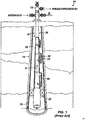
gas lift completion 10 illustrated inFigure 1 has awellhead 12 atop acasing 14 that passes through a formation. Tubing 20 positioned in thecasing 14 has a number ofside pocket mandrels 30 and aproduction packer 22. To conduct a gas lift operation, operators installgas lift valves 40 by slickline into theside pocket mandrels 30. One suitable example of a gas lift valve is the Mcmurry-Macco® gas lift valveavailable from Weatherford-the Assignee of the present disclosure. (McMURRY-MACCO is a registered trademark of WeathertordlLamb, Inc.) - With the
valves 40 installed, compressed gas G from thewellhead 12 is injected into theannulus 16 between theproduction tubing 20 and thecasing 14. In theside pocket mandrels 30, thegas lift valves 40 then act as one-way valves by allowing gas flow from theannulus 16 to thetubing string 20 and preventing gas flow from thetubing 20 to theannulus 16. Downhole, theproduction packer 22 forces produced fluid enteringcasing perforations 15 from the formation to travel up through thetubing 20. Additionally, thepacker 22 keeps the gas flow in theannulus 16 from entering thetubing 20. - The injected gas G passes down the
annulus 16 until it reaches theside pocket mandrels 30. Entering the mandrel's ports 35, the gas G must first pass through thegas lift valve 40 before it can pass into thetubing string 20. Once in thetubing 20, the gas G can then rise to the surface, lifting produced fluid in thetubing 20 in the process. - As noted above, the installed
gas lift valves 40 regulate the flow of gas from theannulus 16 to thetubing 20. To prevent fluid in thetubing 20 from passing out thevalve 40 to theannulus 16, the gas lift valve 40can use a check valve that restricts backflow. - One type of
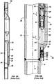
side pocket mandrel 30 is shown in more detail inFigures 2A-2B . Thismandrel 30 is similar to a Double-Valved external (DVX) gas-lift mandrel, such as disclosed inU.S. Pat. No. 7,228,909 incorporated herein by reference in its entirety.Themandrel 30 has aside pocket 32 in an offset bulge from the mandrel'smain passage 31. Thispocket 32 holds thegas lift valve 40 as shown inFigure 2B . The pocket's upper end has aseating profile 33 for engaging a locking mechanism of thegas lift valve 40, while the pocket's other end has anopening 34 to the mandrel'smain passage 31. -
Lower ports 36 in the mandrel'spocket 32 communicate with the surrounding annulus (16) and allow for fluid communication during gas lift operations. As shown inFigures 2A-2B . theseports 36 communicate alongside passages 37 on either side of thepocket 32. When thesepassages 37 reach aseating area 39 of thepocket 32, thesepassages 37 communicate with thepocket 32 viatransverse ports 38. In this way, fluid entering theports 36 can flow along theside passage 37 to thetransverse ports 38 and into theseating area 39 of thepocket 32 where portion of thegas lift valve 40 positions. As shown inFigure 2B , thegas lift valve 40 haspackings 43 that straddle and packoff the exit of theports 38 in the mandrel'sseating area 39. This is whereinlets 42 of thegas lift valve 40 position to receive the flow of gas. - In the current arrangement, the
ports 36 on themandrel 30 can receiveexternal check valves 50 that dispose in theports 36. Thecheck valves 50 allow gas G flow from the annulus (16) into the mandrel'sports 36, but prevent fluid flow in the reverse direction to the annulus (16). In general, thecheck valve 50 has a tubular body having two or moretubular members - The upper end of the
valve 50 threads into the mandrel'sport 36, while the lower end can have female threads for attaching other components thereto. Internally, acompression spring 58 or the like biases acheck dart 55 in the valve's bore against aseat 56. To open the one-way valve 50, pressure from the annulus (16) moves thecheck dart 55 away from theseat 56 against the bias of thespring 58. If backflow occurs, the dart 55can seal against theseat 56 to prevent fluid flow out thecheck valve 50. - During gas lift, for example, the injected gas G can flow through the
check valves 50, continue through separate flow paths in theports 36 andpassage 37, and then flow from thetransverse ports 38 toward theinlets 42 of thegas lift valve 40. In turn, thegas lift valve 40 allows the gas G to flaw downward within thevalve 40, through acheck valve 45, and eventually flow out throughoutlets 44 and into theside pocket 32. From there, the gas G flows out through theslot 34 in themandrel 30 and into the production tubing (20) connected to the mandrel'smain passage 31. - Because the
gas lift valve 40 and theseparate check valves 50 both prevent fluid flow from thetubing 20 into theannulus 16, they can act as redundant backups to one another. Moreover, thecheck valves 50 allow thegas lift valve 40 to be removed from themandrel 30 for repair or replacement, while still preventing flow from thetubing 20 to theannulus 16. This can improve gas lift operations by eliminating the time and cost required to unload production fluid from theannulus 16 as typically encountered when gas lift valves are removed and replaced in conventional mandrels. - Various types of check valves can be used with gas lift valves or with other downhole components. For example,
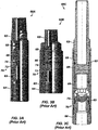
Figures 3A-3C illustrates types of prior art check valves for use with gas lift valves and mandrels. In particular,Figures 3A and 3B respectively show a CV-1check valve 60A and a CV-2check valve 60B from Weatherford's McMurry-Macco.CV series of reverse-flow check valve. Thesecheck valves 60A-B can attach to the bottom of a gaslift valve, to ports of a side pocket mandrel, or other flow-control device. - As shown, the
check valves 60A-B each have anupper housing 62 threadably coupled to atower housing 64 with an O-ring seal 63 therebetween. Disposed in the bore of thevalves 60A-B, adart 66 is biased by aspring 68 toward aseat 70. As shown inFigures 3A-3B , theseat 70 has anelastomeric component 72 and aretainer 74. - Another example of a
check valve 60C is shown inFigure 3C . Thischeck valve 60C is similar to the DVX check valveavailable from Weatherford. Thisparticular check valve 60C is well suited for a Double-Valved External (DVX) gas-lift mandrel described previously with reference toFigures 2A-2B . As shown, thischeck valve 60C includes anupper body 62 coupled to alower body 64 by aport housing 65 and O-rings 63_ As before, thecheck dart 66 can move in theport housing 65 against the bias of aspring 68 relative to aseat 70. Here, theseat 70 has acheck seal 72 typically composed of elastomer (i.e., elastic polymer), such as nitrile butadiene rubber, hydrogenated nitrile butadiene rubber, fluorocarbon rubber, tetra-fluoro-ethylene-propylene, and perfluoroelastomers. - Duringa gaslift operation, upstream pressuretypically from the surrounding annulus acts against the
check valve 60A-C and is higher than the downstream pressure from the tubing. The pressure differential depresses the spring-loadeddart 66 in thevalve 60A-C, allowing injection gas to flow through thecheck valve 60A-C and into the production tubing. If the downstream pressure is greater than the upstream pressure, flow across thecheck dart 66 forces thedart 66 against the seat 17, which prevents backflow. In the seating process, an elastomeric seal is first established between thedart 66 andelastomeric component 72. As the differential pressure increases, a metal-to-metal seal is then formed for additional protection between thedart 66 and portion of thelower housing 64 forming part oftheseat 70. - As seen in
Figures 3A-3C ,check valves 60A-C for gas lift valves use elastomericresilient seals 72 to provide a secondary seal to the metal-to-metal seal between thecheck dart 66 and theseat 70. As expected, such a dual seal protects against backflow, prevents casing from damage, and avoids costly workover operations. Unfortunately, theelastomeric seal 72 can be prone to explosivedecompression during use. - In explosive decompression, the
seal 72 is exposed to gas laden fluid at high pressure, and the compressed gas enters the interstices of the seal's elastomer. As long as operating pressures remain high, theseal 72 remains intact. Whenever the pressure falls, however, the gas in the elastomer of theseal 72 expands and can cause theseal 72 to rupture. - Explosive decompression has been a recognized problem in valve seals, and two solutions have been developed for handling it. In a first solution, specific types of elastomers have been developed that are more resistant than others to explosive decompression. An example of such an elastomer is FKM XploR V9T20, which is available from Trelleborg Sealing Solutions. Although these types of elastomers may be useful, even seals with such elastomers can still have issues with explosive decompression in check valves used for gas lift operations.
- Another solution developed in the art has been to use only metal-to-metal sealingwith no resilient seal in check valves. An example of such a check valve with only metal-to-metal sealing is the 15K Severe Service MTM Check Valve available from Halliburton, Although exclusive metal sealing may solve problems related to explosive decompression, a check valve utilizing only a metal-ta-metal seal can be less reliable in sealing, especially if there is any debris present in the injection fluid. Moreover, the exclusive metal-to-metal seal can be costly to manufacture and maintain.
- The subject matter of the present disclosure is directed to overcoming, or at least reducing the effects of, one or more of the problems set forth above.
- A check valve apparatus for a gas lift application can be used as an external check valve attached to the outside of a side pocket mandrel that holds a gas lift valve therein. Atternatively, the check valve apparatus can actually be part of a gas lift valve or any other type of valve.
- The apparatus has a valve body with a seat and dart disposed in the valve's bore. The seat has a first seal element composed of a non-elastomeric material and has a second seal element composed of a metal material. Being non-elastomeric material, the first seal element can be composed of a thermoplastic, such as polytetrafluoroethylene (PTFE), a moly-filed PTFE, or polyetheretherketone (PEEK). A biasing element, such as a spring, resiliently biases this first (non-elastomeric) seal element of the seat to provide resiliency to the seal produced.
- When the dart composed of a metal material moves in the valve's bore relative to the seat,the dart allows or prevents flow through the valve body by engaging or disengaging the seat. When exposed to proper flow from the annulus to the mandrel, the dart moves against the bias of the dart's spring away from the seat. When exposed to a first differential pressure from backflow, however, the dart engages the first (non-elastomeric) seal element resiliently biased by the biasing element. When exposed to a greater differential pressure, the dart further engages the second (metal) seal element, which can include portion of the valve body in the bore.
- In one arrangement, the biasing element is an energized seal disposed in a face seal configuration that biases the first seal element axially along the bore. This energized seal can be a metal spring energized seal having a jacket with a metal finger spring disposed therein. In another arrangement, the first seal element can be a jacket of an energized seal, while the biasing element is a spring of the energized seal disposed in the jacket. The energized seal in this arrangement can be a metal spring energized seal disposed in a rod and piston seal configuration and can bias transversely to the bore. The spring can use a coil spring for this energized seal.
- The foregoing summary is not intended to summarize each potential embodiment or every aspect of the present disclosure.
-
Fig. 1 illustrates a typical gas lift completion. -
Fig. 2A illustrates a side pocket mandrel according to the prior art for use with dual external check valves. -
Fig. 2B illustrates portion of a gas lift valve positioned in the side pocket mandrel ofFig. 2A with an external check valve disposed thereon. -
Figs. 3A-3C illustrate prior art check valves. -
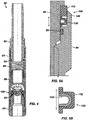
Fig. 4 illustrates a cross-section of a check valve with one seat arrangement according to certain teachings of the present disclosure. -
Fig. 5A illustrates a detail of the seat arrangement for the check valve ofFig. 4 . -
Fig. 5B illustrates a cross-sectional detail of the spring loaded cup seal for the disclosed seat arrangement. -
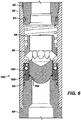
Fig. 6 illustrates a cross-section of a check valve with another seat arrangement according to certain teachings of the present disclosure. -
Fig. 7A illustrates a detail of the seat arrangement for the check valve ofFig. 6 . -
Fig. 7B illustrates another configuration for the seat arrangement ofFig. 6 . -
Fig. 7C illustrates various energized seals for use in the seat arrangements of the present disclosure. -
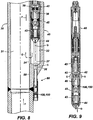
Fig. 8 illustrates a side pocket mandrel with an external check valve having the disclosed seat arrangement. -
Fig. 9 illustrates a gas lift valve having the disclosed seat arrangement. - A gas
lift check valve 80 illustrated inFigure 4 has aseat arrangement 100 according to the present disclosure. As before, thecheck valve 80 includes anupper body 82 coupled to alower body 84 by aport housing 85 and O-rings 83. Acheck dart 86 can move in theport housing 85 against the bias of aspring 88 relative to theseat arrangement 100. - This
valve 80 is well suited for the Double-Valved external (DVX) gas-lift mandrel, such as described previously with reference toFigures 2A-2B and disclosed in the incorporatedU.S. Pat. No. 7,228,909 . However, thecheck valve 80 with itsseat arrangement 100 can be used in other implementations and can be attached directly to a gas lift valve or other flow control device that either has or does not have its own one-way valve. Moreover,multiple check valves 80 can be screwed together to create multiple check barriers for additional protection against backflow. - As shown in
Figure 5A , theseat arrangement 100 includes acheck seal 110 and a spring loadedcup seal 130 arranged between theport housing 85 and thelower body 84. Thecheck seal 110 is composed of non-elastomeric material, such as polytetrafluoroethylene (PTFE) or moly-filed PTFE (i.e., polytetrafluoroethylene, molybdenum sulfide (MoS2) Filled, which is also known as Teflon®). (TEFLON is a registered trademark of E. I. Du Pont De Nemours and Company Corporation.) Other suitable materials that are non-elastomeric include other thermoplastic polymers. - Because the
check seal 110 is non-elastomeric, it lacks the resiliency typically provided for check valve seals using elastomer. For this reason, the spring loadedcup seal 130 is used to provide resiliency to theseat arrangement 100. Thecup seat 130 is arranged in a face seal configuration and biases thecheck seal 110 relative to thelower housing 84. As shown in the cross-sectional detail ofFigure 5B , the spring loadedcup seal 130 has ajacket 132 in which aspring element 134 is disposed. The jacket 132is composed of non-elastomeric material, such as PTFE or the like, while thespring element 134 is composed of non-corrosive metal or other suitable material. - As shown in
Figures 4 and 5A , the resiliency of thecup seal 130 acts axially along thevalve 80 and acts against the seating direction of thedart 86. As fluid pressure in thevalve 80 builds and/or the bias of thespring 88 acts to seat thedart 86 on theseat arrangement 100, thecheck dart 66 engages theseat arrangement 100 to prevent backflow. In the seating process, the non-elastomeric seal from thecheck seal 110 is first established with thedart 66, and the resiliency for this seal is provided by the bias of thecup seal 130. As the differential pressure increases, a metal-to-metal seal is then formed for additional protection, as thedart 66 engages an inside metal area 140 (Fig. SA) of thelower housing 84 around the valve'sseat arrangement 100. - Another
seat arrangement 150 for thecheck valve 80 illustrated inFigure 6 has a spring loadedcup seal 160 and a retainingelement 180.Figure 7A illustrates a detail of thecheck seal 160 for the check valve ofFigure 6 , whileFigure 7B illustrates the spring loadedcup seal 160 in greater detail relative to thecheck dart 86 and other valve components. InFigures 6 and7A-7B , components of thevalve 80 are similar to those described previously so the same reference numerals are used. - As before, the
seat arrangement 150 uses a non-elastomeric material and a spring mechanism for thecheck seal 160. Thisseat arrangement 150 differs somewhat from theprevious arrangement 100 in that the bias or resiliency of thecheck seal 160 is orthogonal to the axis of thecheck valve 80. Rather than a face configuration, for example, thecheck seal 160 is disposed in a rod and piston seal configuration. As shown inFigures 7A-7B , the resiliency of thecheck seal 160 therefore acts transversely to thevalve 80's longitudinal axis. In this way, thecheck seal 160 presses outward into the valve's bore and acts orthogonally to the seating direction of thedart 86 as shown inFigure 7B . - As shown in
Figure 6 , the retainingelement 180 can be composed of non-elastomeric material, such as PTFE or metal. Disposed between the matedhousings element 180 helps retain or hold thecheck seal 160 and may facilitate assembly. As an alternative shown inFigure 7B , theseat arrangement 150 can lack a retaining element (180). Instead, thelower housing portion 84 is configured to directly retain thecheck seal 160 as well as provide the metal area for the metal-to-metal seal with thecheck dart 86. As will be appreciated, these and other suitable configurations can be used to retain thecheck seal 160 in thevalve 80. - As best shown in
Figures 7A-7B , thecheck seal 160 has ajacket 162, acoil spring 164, and ahat ring 164. Thejacket 162 andhat ring 164 are both preferably composed on non-elastomeric materials. For example, thejacket 162 can be composed of PTFE, such asAvalon ® 56 or the like, while thehat ring 164 can be composed of polyetheretherketone (PEEK), such as Arion® 1000 or the like. (AVALON and ARLON are registered trademarks of Green, Tweed & Co. of Kulpsville, Pennsylvania.) Thecoil spring 164 is preferably composed of corrosive resistant metal, such as Elgiloy® 58%Cr or the like. (ELGILOY is a registered trademark of Elgiloy Company.) - As shown in
Figures 6 and7A-7B , fluid pressure in thevalve 80 builds and/or the bias of the spring'88 acts to seat thedart 86 on theseat arrangement 150 so thecheck dart 66 engages theseat arrangement 150 to prevent backflow. In the seating process, the non-elastomeric seal fromcheck seal 160 is first established with thedart 66, and the resiliency for this seal is provided transversely by the biasing element of thecheck seal 160. As the differential pressure increases, a metal-to-metal seal is then formed for additional protection, as thedart 66 engages aninside metal area 184 around the valve'sseat arrangement 150. - As evidenced by the present disclosure, the disclosed seat arrangements (i.e., 100 and 150) can overcome issues typically encountered in check valves. By using the non-elastomeric material for the resilient seal, for example,issues with explosive decompression can be avoided completely, yet the seal can still provide high sealing integrity even if debris is present The biasing elements(e.g.,
cup seal 130 or spring loaded check seal 160) give resiliency to theseat arrangements seat arrangements check valve 80 and further enhances the seal produced. - The
seating arrangements Figure 7C showsvarious energizedseals 190A-C that can be used as a resiliency element (as inFig. 5A ), a check seal element (as inFig. 6 ), or both. - In general, the energized seals 190A-Chave a ring-shaped
jacket 191 composed of non-elastomeric polymer, such as PTFE, and have abiasing element polymer jacket 191. When seated in thejacket 191, the biasingelement anergizedseals 190A-C can use biasing elements, including afinger spring 192, acoil spring 194, and adouble coil spring 196, each of which is preferably composed of metal. By contrast, seal 190D uses an O-ring 198 in thejacket 191 and may be suitable for some applications. - As noted herein, the
check valve 80 ofFigure 6 can attach to the port of a side pocket mandrel. For example,Figure 8 shows thecheck valve 80 having the disclosed seat arrangement 100,150 attached to theexternal port 36 of theside pocket mandrel 30. (Similar reference numbers are used for like components discussed previously.) Thevalve 80 can thread into theexternal port 36 or attach in any other suitable manner. In this way, thevalve 80 can act as a redundant check valve to prevent backflow and can operate as the one-way valve when thegas lift valve 40 is removed from theside pocket 32 for repair or replacement. - Although discussed in relation to an external check valve, the disclosed seat arrangements 100,150 may actually be used with any poppet-type sealing device that requires a gas tight seal. As one example, even a
gas lift valve 40 as shown inFigure 9 can use the seat arrangement 100,150 of the present disclosure in conjunction with itsinternal check dart 48. (Similar reference numbers are used for like components discussed previously.) - As shown, the retrievable, one-way check valve in the
gas lift valves 40 disposing in a side pocket mandrel may use the disclosed seat arrangement 100,150. In this way, the seat arrangement 100,150 operates in conjunction with the gas lift valve'sdart 48 to allow flow through the valve'sinternal passage 46 from theinlets 42 to theoutlets 44 and prevent backflow in the reverse direction. - The foregoing description of preferred and other embodiments is not intended to limit or restrict the scope or applicability of the inventive concepts conceived of by the Applicants. Various types of materials have been discussed herein. For the sake of understanding and without limitation to the claims and available materials, elastomer refers to polymers that are elastic (i.e., NBR, HNBR, FKM, TFE/P, FFKM, and the like), while thermoplastic refers to polymers that are not elastic and do not recover upon deformation (i.e., PTFE, PEEK, PPS, PAI, PA, EDPM+PP, PVDF, ECTFE, and the like).
- In exchange for disclosing the inventive concepts contained herein, the Applicants desire all patent rights afforded by the appended claims. Therefore, it is intended that the appended claims include all modifications and alterations to the full extent that they come within the scope of the following claims or the equivalents thereof.
Claims (15)
- A check valve apparatus for a gas lift application, comprising:a body defining a bore;a seat disposed in the bore and having first and second seal elements, the first seal element being composed of a non-elastomeric material, the second seal element being composed of a metal material;a biasing element resiliently biasing the first seal element of the seat; anda dart composed of a metal material and movably disposed in the bore relative to the seat for sealably engaging the first and second seal elements.
- The apparatus of claim 1, wherein the non-elastomeric material of the first seal element comprises a thermoplastic selected from the group consisting of polytetrafluoroethylene (PTFE), a moly-filed PTFE, and polyetheretherketone (PEEK).
- The apparatus of claim 1 or 2, wherein the second seal element comprises a portion of the valve body in the bore.
- The apparatus of claim 2 or 3, wherein the biasing element comprises an energized seal disposed in a face seal configuration and biasing the first seal element axially along the bore.
- The apparatus of claim 4, wherein the energized seal comprises a jacket with a spring disposed therein.
- The apparatus of claim 5, where the jacket is composed of a non-elastomeric material, and wherein the spring is composed of a metal material.
- The apparatus of any preceding claim, wherein the first seal element comprises a jacket of an energized seal, and wherein the biasing element comprises a spring of the energized seal disposed in the jacket.
- The apparatus of claim 7, wherein the energized seal is disposed in a rod and piston seal configuration and biased transversely to the bore.
- The apparatus of claim 8, wherein the energized seal comprises a ring disposed on the jacket and covering the spring disposed in the jacket.
- The apparatus of claim 5, 6, 7, 8 or 9, wherein the spring comprises a finger spring, a coil spring, or a double-coil spring.
- The apparatus of any preceding claim, wherein the valve body is adapted to couple to an external port on a side pocket mandrel, or wherein the vahre body is adapted to dispose in a side pocket of a side pocket mandrel.
- The apparatus of any preceding claim, wherein the dart exposed to at least a first differential pressure engages the first seal element resiliently biased by the biasing element to form a resilient seal, and wherein the dart exposed to at least a second differential pressure greater than the first differential pressure engages the second seal element to form a metal-to-metal seal in addition to the resilient seal.
- A gas lift apparatus for use in a wellbore, comprising:a mandrel having a side pocket and defining an external port therein, the side pocket adapted to hold a retrievable one-way valve for preventing fluid flow from within the mandrel to outside the mandrel through the external port; andat least one check valve as claimed in any preceding claim attaching to the external port of the mandrel and in fluid communication with the side pocket, the at least one check valve for preventing fluid flow from within the side pocket or the one-way valve to outside the mandrel.
- A gas lift apparatus for use in a wellbore, comprising:a mandrel having a side pocket therein; anda first check valve as claimed in any of claims 1 to 12 retrievably disposing in the side pocket of the mandrel and preventing fluid flow from within the mandrel to outside the mandrel.
- The apparatus of claim 14, further comprising a second check valve attached to the mandrel and in fluid communication with the side pocket, the second check valve preventing fluid flow from within the side pocket or the first check valve to outside the mandrel.
Applications Claiming Priority (1)
| Application Number | Priority Date | Filing Date | Title |
|---|---|---|---|
| US13/027,676 US8763706B2 (en) | 2011-02-15 | 2011-02-15 | Self-boosting, non-elastomeric resilient seal for check valve |
Publications (3)
| Publication Number | Publication Date |
|---|---|
| EP2489827A2 true EP2489827A2 (en) | 2012-08-22 |
| EP2489827A3 EP2489827A3 (en) | 2013-03-27 |
| EP2489827B1 EP2489827B1 (en) | 2015-07-22 |
Family
ID=45656755
Family Applications (1)
| Application Number | Title | Priority Date | Filing Date |
|---|---|---|---|
| EP12250030.9A Not-in-force EP2489827B1 (en) | 2011-02-15 | 2012-02-14 | Self-boosting, non-elastomeric resilient seal for check valve |
Country Status (2)
| Country | Link |
|---|---|
| US (1) | US8763706B2 (en) |
| EP (1) | EP2489827B1 (en) |
Families Citing this family (26)
| Publication number | Priority date | Publication date | Assignee | Title |
|---|---|---|---|---|
| US9605521B2 (en) | 2012-09-14 | 2017-03-28 | Weatherford Technology Holdings, Llc | Gas lift valve with mixed bellows and floating constant volume fluid chamber |
| KR101592536B1 (en) * | 2013-12-23 | 2016-02-05 | 김영정 | Fluid circulation type heating apparatus |
| US9518674B2 (en) | 2014-03-07 | 2016-12-13 | Senior Ip Gmbh | High pressure valve assembly |
| US9519292B2 (en) | 2014-03-07 | 2016-12-13 | Senior Ip Gmbh | High pressure valve assembly |
| US9765603B2 (en) | 2014-11-26 | 2017-09-19 | General Electric Company | Gas lift valve assemblies and methods of assembling same |
| US9689241B2 (en) | 2014-11-26 | 2017-06-27 | General Electric Company | Gas lift valve assemblies having fluid flow barrier and methods of assembling same |
| CA2918007C (en) | 2015-01-15 | 2022-10-18 | Flowco Production Solutions, LLC | Robust bumper spring assembly |
| US9624996B2 (en) | 2015-01-15 | 2017-04-18 | Flowco Production Solutions, LLC | Robust bumper spring assembly |
| US9915133B2 (en) * | 2015-02-20 | 2018-03-13 | Flowco Production Solutions, LLC | Unibody bypass plunger with centralized helix and crimple feature |
| CA2921175C (en) * | 2015-02-20 | 2023-09-26 | Flowco Production Solutions, LLC | Improved dart valves for bypass plungers |
| US11578570B2 (en) * | 2015-02-20 | 2023-02-14 | Flowco Production Solutions, LLC | Unibody bypass plunger and valve cage with sealable ports |
| US10669824B2 (en) | 2015-02-20 | 2020-06-02 | Flowco Production Solutions, LLC | Unibody bypass plunger and valve cage with sealable ports |
| US10161230B2 (en) | 2016-03-15 | 2018-12-25 | Patriot Artificial Lift, LLC | Well plunger systems |
| US10125874B2 (en) | 2016-10-24 | 2018-11-13 | Flowserve Management Company | Valves including multiple seats and related assemblies and methods |
| CN106522899A (en) * | 2016-11-03 | 2017-03-22 | 中国石油化工股份有限公司 | Fixed type spring gas lift valve |
| US10605049B2 (en) | 2016-11-21 | 2020-03-31 | Weatherford Technology Holdings, Llc | Chemical injection valve with enhanced sealing capability |
| US10760376B2 (en) | 2017-03-03 | 2020-09-01 | Baker Hughes, A Ge Company, Llc | Pressure control valve for downhole treatment operations |
| US10480661B2 (en) * | 2017-09-06 | 2019-11-19 | Baker Hughes, A Ge Company, Llc | Leak rate reducing sealing device |
| WO2019173520A1 (en) | 2018-03-06 | 2019-09-12 | Flowco Production Solutions, LLC | Internal valve plunger |
| US10662737B2 (en) * | 2018-07-24 | 2020-05-26 | Baker Hughes, A Ge Company, Llc | Fluid injection valve |
| US20220056785A1 (en) * | 2018-09-13 | 2022-02-24 | Flowco Production Solutions, LLC | Unibody bypass plunger with integral dart valve cage |
| US11293267B2 (en) | 2018-11-30 | 2022-04-05 | Flowco Production Solutions, LLC | Apparatuses and methods for scraping |
| USD937982S1 (en) | 2019-05-29 | 2021-12-07 | Flowco Production Solutions, LLC | Apparatus for a plunger system |
| US11448049B2 (en) | 2019-09-05 | 2022-09-20 | Flowco Production Solutions, LLC | Gas assisted plunger lift control system and method |
| BR102020012768A2 (en) * | 2020-06-22 | 2022-01-04 | Petróleo Brasileiro S.A. - Petrobras | CHEMICAL SET FOR CHEMICAL INJECTION IN OIL WELLS |
| EP4321725A1 (en) * | 2022-08-08 | 2024-02-14 | Jmi Mfg | Double barrier gas lift flow control device |
Citations (1)
| Publication number | Priority date | Publication date | Assignee | Title |
|---|---|---|---|---|
| US7228909B2 (en) | 2004-12-28 | 2007-06-12 | Weatherford/Lamb, Inc. | One-way valve for a side pocket mandrel of a gas lift system |
Family Cites Families (8)
| Publication number | Priority date | Publication date | Assignee | Title |
|---|---|---|---|---|
| US3059700A (en) | 1960-12-30 | 1962-10-23 | Jersey Prod Res Co | Gas lift mandrel for use in wells |
| US3967679A (en) * | 1975-02-21 | 1976-07-06 | Smith International, Inc. | Mud saver valve |
| US4407362A (en) | 1981-06-10 | 1983-10-04 | Otis Engineering Corporation | Flow control apparatus for wells |
| US20050126638A1 (en) | 2003-12-12 | 2005-06-16 | Halliburton Energy Services, Inc. | Check valve sealing arrangement |
| GB0409619D0 (en) * | 2004-04-30 | 2004-06-02 | Specialised Petroleum Serv Ltd | Valve seat |
| GB0515071D0 (en) | 2005-07-22 | 2005-08-31 | Moyes Peter B | Non-return valve |
| US20100308517A1 (en) * | 2009-06-04 | 2010-12-09 | James Edward Goodson | Coated spring and method of making the same |
| CA2765581A1 (en) | 2009-06-17 | 2010-12-23 | Schlumberger Canada Limited | Compliant dart-style reverse-flow check valve |
-
2011
- 2011-02-15 US US13/027,676 patent/US8763706B2/en not_active Expired - Fee Related
-
2012
- 2012-02-14 EP EP12250030.9A patent/EP2489827B1/en not_active Not-in-force
Patent Citations (1)
| Publication number | Priority date | Publication date | Assignee | Title |
|---|---|---|---|---|
| US7228909B2 (en) | 2004-12-28 | 2007-06-12 | Weatherford/Lamb, Inc. | One-way valve for a side pocket mandrel of a gas lift system |
Also Published As
| Publication number | Publication date |
|---|---|
| US20120204977A1 (en) | 2012-08-16 |
| US8763706B2 (en) | 2014-07-01 |
| EP2489827A3 (en) | 2013-03-27 |
| EP2489827B1 (en) | 2015-07-22 |
Similar Documents
| Publication | Publication Date | Title |
|---|---|---|
| EP2489827B1 (en) | Self-boosting, non-elastomeric resilient seal for check valve | |
| US6664572B2 (en) | Valve seal assemblies and methods | |
| US7708066B2 (en) | Full bore valve for downhole use | |
| US9010353B2 (en) | Gas lift valve having edge-welded bellows and captive sliding seal | |
| US9033054B2 (en) | Metal to metal seal for downhole tools | |
| US10577889B2 (en) | Constructed annular safety valve element package | |
| US9157297B2 (en) | Pump-through fluid loss control device | |
| US11255157B2 (en) | Chemical injection valve with stem bypass flow | |
| US10161232B2 (en) | Lift valve with bellow hydraulic protection and chatter reduction | |
| US20080169610A1 (en) | Metal to metal seal for downhole tools | |
| US9765603B2 (en) | Gas lift valve assemblies and methods of assembling same | |
| US7926569B1 (en) | Bypass device for wellbores | |
| US11459861B1 (en) | Double barrier gas lift flow control device | |
| US11585193B1 (en) | Double barrier gas lift flow control device | |
| EP4321725A1 (en) | Double barrier gas lift flow control device |
Legal Events
| Date | Code | Title | Description |
|---|---|---|---|
| PUAI | Public reference made under article 153(3) epc to a published international application that has entered the european phase |
Free format text: ORIGINAL CODE: 0009012 |
|
| 17P | Request for examination filed |
Effective date: 20120225 |
|
| AK | Designated contracting states |
Kind code of ref document: A2 Designated state(s): AL AT BE BG CH CY CZ DE DK EE ES FI FR GB GR HR HU IE IS IT LI LT LU LV MC MK MT NL NO PL PT RO RS SE SI SK SM TR |
|
| AX | Request for extension of the european patent |
Extension state: BA ME |
|
| PUAL | Search report despatched |
Free format text: ORIGINAL CODE: 0009013 |
|
| AK | Designated contracting states |
Kind code of ref document: A3 Designated state(s): AL AT BE BG CH CY CZ DE DK EE ES FI FR GB GR HR HU IE IS IT LI LT LU LV MC MK MT NL NO PL PT RO RS SE SI SK SM TR |
|
| AX | Request for extension of the european patent |
Extension state: BA ME |
|
| RIC1 | Information provided on ipc code assigned before grant |
Ipc: E21B 34/10 20060101AFI20130221BHEP Ipc: E21B 43/12 20060101ALI20130221BHEP |
|
| RBV | Designated contracting states (corrected) |
Designated state(s): AL AT BE BG CH CY CZ DE DK EE ES FI FR GB GR HR HU IE IS IT LI LT LU LV MC MK MT NL NO PL PT RO RS SE SI SK SM TR |
|
| RAP1 | Party data changed (applicant data changed or rights of an application transferred) |
Owner name: WEATHERFORD/LAMB, INC. |
|
| GRAP | Despatch of communication of intention to grant a patent |
Free format text: ORIGINAL CODE: EPIDOSNIGR1 |
|
| INTG | Intention to grant announced |
Effective date: 20150205 |
|
| RAP1 | Party data changed (applicant data changed or rights of an application transferred) |
Owner name: WEATHERFORD TECHNOLOGY HOLDINGS, LLC |
|
| GRAS | Grant fee paid |
Free format text: ORIGINAL CODE: EPIDOSNIGR3 |
|
| GRAA | (expected) grant |
Free format text: ORIGINAL CODE: 0009210 |
|
| AK | Designated contracting states |
Kind code of ref document: B1 Designated state(s): AL AT BE BG CH CY CZ DE DK EE ES FI FR GB GR HR HU IE IS IT LI LT LU LV MC MK MT NL NO PL PT RO RS SE SI SK SM TR |
|
| REG | Reference to a national code |
Ref country code: GB Ref legal event code: FG4D |
|
| REG | Reference to a national code |
Ref country code: CH Ref legal event code: EP |
|
| REG | Reference to a national code |
Ref country code: IE Ref legal event code: FG4D |
|
| REG | Reference to a national code |
Ref country code: AT Ref legal event code: REF Ref document number: 738053 Country of ref document: AT Kind code of ref document: T Effective date: 20150815 |
|
| REG | Reference to a national code |
Ref country code: DE Ref legal event code: R096 Ref document number: 602012008917 Country of ref document: DE |
|
| REG | Reference to a national code |
Ref country code: NO Ref legal event code: T2 Effective date: 20150722 |
|
| REG | Reference to a national code |
Ref country code: AT Ref legal event code: MK05 Ref document number: 738053 Country of ref document: AT Kind code of ref document: T Effective date: 20150722 |
|
| REG | Reference to a national code |
Ref country code: NL Ref legal event code: FP |
|
| REG | Reference to a national code |
Ref country code: LT Ref legal event code: MG4D |
|
| PG25 | Lapsed in a contracting state [announced via postgrant information from national office to epo] |
Ref country code: GR Free format text: LAPSE BECAUSE OF FAILURE TO SUBMIT A TRANSLATION OF THE DESCRIPTION OR TO PAY THE FEE WITHIN THE PRESCRIBED TIME-LIMIT Effective date: 20151023 Ref country code: FI Free format text: LAPSE BECAUSE OF FAILURE TO SUBMIT A TRANSLATION OF THE DESCRIPTION OR TO PAY THE FEE WITHIN THE PRESCRIBED TIME-LIMIT Effective date: 20150722 Ref country code: LT Free format text: LAPSE BECAUSE OF FAILURE TO SUBMIT A TRANSLATION OF THE DESCRIPTION OR TO PAY THE FEE WITHIN THE PRESCRIBED TIME-LIMIT Effective date: 20150722 Ref country code: LV Free format text: LAPSE BECAUSE OF FAILURE TO SUBMIT A TRANSLATION OF THE DESCRIPTION OR TO PAY THE FEE WITHIN THE PRESCRIBED TIME-LIMIT Effective date: 20150722 |
|
| PG25 | Lapsed in a contracting state [announced via postgrant information from national office to epo] |
Ref country code: PT Free format text: LAPSE BECAUSE OF FAILURE TO SUBMIT A TRANSLATION OF THE DESCRIPTION OR TO PAY THE FEE WITHIN THE PRESCRIBED TIME-LIMIT Effective date: 20151123 Ref country code: AT Free format text: LAPSE BECAUSE OF FAILURE TO SUBMIT A TRANSLATION OF THE DESCRIPTION OR TO PAY THE FEE WITHIN THE PRESCRIBED TIME-LIMIT Effective date: 20150722 Ref country code: PL Free format text: LAPSE BECAUSE OF FAILURE TO SUBMIT A TRANSLATION OF THE DESCRIPTION OR TO PAY THE FEE WITHIN THE PRESCRIBED TIME-LIMIT Effective date: 20150722 Ref country code: SE Free format text: LAPSE BECAUSE OF FAILURE TO SUBMIT A TRANSLATION OF THE DESCRIPTION OR TO PAY THE FEE WITHIN THE PRESCRIBED TIME-LIMIT Effective date: 20150722 Ref country code: HR Free format text: LAPSE BECAUSE OF FAILURE TO SUBMIT A TRANSLATION OF THE DESCRIPTION OR TO PAY THE FEE WITHIN THE PRESCRIBED TIME-LIMIT Effective date: 20150722 Ref country code: IS Free format text: LAPSE BECAUSE OF FAILURE TO SUBMIT A TRANSLATION OF THE DESCRIPTION OR TO PAY THE FEE WITHIN THE PRESCRIBED TIME-LIMIT Effective date: 20151122 Ref country code: RS Free format text: LAPSE BECAUSE OF FAILURE TO SUBMIT A TRANSLATION OF THE DESCRIPTION OR TO PAY THE FEE WITHIN THE PRESCRIBED TIME-LIMIT Effective date: 20150722 Ref country code: ES Free format text: LAPSE BECAUSE OF FAILURE TO SUBMIT A TRANSLATION OF THE DESCRIPTION OR TO PAY THE FEE WITHIN THE PRESCRIBED TIME-LIMIT Effective date: 20150722 |
|
| REG | Reference to a national code |
Ref country code: DE Ref legal event code: R097 Ref document number: 602012008917 Country of ref document: DE |
|
| PG25 | Lapsed in a contracting state [announced via postgrant information from national office to epo] |
Ref country code: DK Free format text: LAPSE BECAUSE OF FAILURE TO SUBMIT A TRANSLATION OF THE DESCRIPTION OR TO PAY THE FEE WITHIN THE PRESCRIBED TIME-LIMIT Effective date: 20150722 Ref country code: SK Free format text: LAPSE BECAUSE OF FAILURE TO SUBMIT A TRANSLATION OF THE DESCRIPTION OR TO PAY THE FEE WITHIN THE PRESCRIBED TIME-LIMIT Effective date: 20150722 Ref country code: IT Free format text: LAPSE BECAUSE OF FAILURE TO SUBMIT A TRANSLATION OF THE DESCRIPTION OR TO PAY THE FEE WITHIN THE PRESCRIBED TIME-LIMIT Effective date: 20150722 Ref country code: EE Free format text: LAPSE BECAUSE OF FAILURE TO SUBMIT A TRANSLATION OF THE DESCRIPTION OR TO PAY THE FEE WITHIN THE PRESCRIBED TIME-LIMIT Effective date: 20150722 Ref country code: CZ Free format text: LAPSE BECAUSE OF FAILURE TO SUBMIT A TRANSLATION OF THE DESCRIPTION OR TO PAY THE FEE WITHIN THE PRESCRIBED TIME-LIMIT Effective date: 20150722 |
|
| PLBE | No opposition filed within time limit |
Free format text: ORIGINAL CODE: 0009261 |
|
| STAA | Information on the status of an ep patent application or granted ep patent |
Free format text: STATUS: NO OPPOSITION FILED WITHIN TIME LIMIT |
|
| PG25 | Lapsed in a contracting state [announced via postgrant information from national office to epo] |
Ref country code: RO Free format text: LAPSE BECAUSE OF FAILURE TO SUBMIT A TRANSLATION OF THE DESCRIPTION OR TO PAY THE FEE WITHIN THE PRESCRIBED TIME-LIMIT Effective date: 20150722 Ref country code: BE Free format text: LAPSE BECAUSE OF NON-PAYMENT OF DUE FEES Effective date: 20160229 |
|
| 26N | No opposition filed |
Effective date: 20160425 |
|
| PG25 | Lapsed in a contracting state [announced via postgrant information from national office to epo] |
Ref country code: SI Free format text: LAPSE BECAUSE OF FAILURE TO SUBMIT A TRANSLATION OF THE DESCRIPTION OR TO PAY THE FEE WITHIN THE PRESCRIBED TIME-LIMIT Effective date: 20150722 |
|
| REG | Reference to a national code |
Ref country code: DE Ref legal event code: R119 Ref document number: 602012008917 Country of ref document: DE |
|
| REG | Reference to a national code |
Ref country code: NO Ref legal event code: MMEP |
|
| PG25 | Lapsed in a contracting state [announced via postgrant information from national office to epo] |
Ref country code: MC Free format text: LAPSE BECAUSE OF FAILURE TO SUBMIT A TRANSLATION OF THE DESCRIPTION OR TO PAY THE FEE WITHIN THE PRESCRIBED TIME-LIMIT Effective date: 20150722 Ref country code: LU Free format text: LAPSE BECAUSE OF FAILURE TO SUBMIT A TRANSLATION OF THE DESCRIPTION OR TO PAY THE FEE WITHIN THE PRESCRIBED TIME-LIMIT Effective date: 20160214 |
|
| REG | Reference to a national code |
Ref country code: CH Ref legal event code: PL |
|
| GBPC | Gb: european patent ceased through non-payment of renewal fee |
Effective date: 20160214 |
|
| PG25 | Lapsed in a contracting state [announced via postgrant information from national office to epo] |
Ref country code: CH Free format text: LAPSE BECAUSE OF NON-PAYMENT OF DUE FEES Effective date: 20160229 Ref country code: NO Free format text: LAPSE BECAUSE OF NON-PAYMENT OF DUE FEES Effective date: 20160229 Ref country code: LI Free format text: LAPSE BECAUSE OF NON-PAYMENT OF DUE FEES Effective date: 20160229 |
|
| REG | Reference to a national code |
Ref country code: NL Ref legal event code: MM Effective date: 20160301 |
|
| REG | Reference to a national code |
Ref country code: FR Ref legal event code: ST Effective date: 20161028 |
|
| REG | Reference to a national code |
Ref country code: IE Ref legal event code: MM4A |
|
| PG25 | Lapsed in a contracting state [announced via postgrant information from national office to epo] |
Ref country code: BE Free format text: LAPSE BECAUSE OF FAILURE TO SUBMIT A TRANSLATION OF THE DESCRIPTION OR TO PAY THE FEE WITHIN THE PRESCRIBED TIME-LIMIT Effective date: 20150722 |
|
| PG25 | Lapsed in a contracting state [announced via postgrant information from national office to epo] |
Ref country code: NL Free format text: LAPSE BECAUSE OF NON-PAYMENT OF DUE FEES Effective date: 20160301 Ref country code: FR Free format text: LAPSE BECAUSE OF NON-PAYMENT OF DUE FEES Effective date: 20160229 Ref country code: DE Free format text: LAPSE BECAUSE OF NON-PAYMENT OF DUE FEES Effective date: 20160901 Ref country code: IE Free format text: LAPSE BECAUSE OF NON-PAYMENT OF DUE FEES Effective date: 20160214 Ref country code: GB Free format text: LAPSE BECAUSE OF NON-PAYMENT OF DUE FEES Effective date: 20160214 |
|
| PG25 | Lapsed in a contracting state [announced via postgrant information from national office to epo] |
Ref country code: MT Free format text: LAPSE BECAUSE OF FAILURE TO SUBMIT A TRANSLATION OF THE DESCRIPTION OR TO PAY THE FEE WITHIN THE PRESCRIBED TIME-LIMIT Effective date: 20150722 |
|
| PG25 | Lapsed in a contracting state [announced via postgrant information from national office to epo] |
Ref country code: SM Free format text: LAPSE BECAUSE OF FAILURE TO SUBMIT A TRANSLATION OF THE DESCRIPTION OR TO PAY THE FEE WITHIN THE PRESCRIBED TIME-LIMIT Effective date: 20150722 Ref country code: HU Free format text: LAPSE BECAUSE OF FAILURE TO SUBMIT A TRANSLATION OF THE DESCRIPTION OR TO PAY THE FEE WITHIN THE PRESCRIBED TIME-LIMIT; INVALID AB INITIO Effective date: 20120214 Ref country code: CY Free format text: LAPSE BECAUSE OF FAILURE TO SUBMIT A TRANSLATION OF THE DESCRIPTION OR TO PAY THE FEE WITHIN THE PRESCRIBED TIME-LIMIT Effective date: 20150722 |
|
| PG25 | Lapsed in a contracting state [announced via postgrant information from national office to epo] |
Ref country code: TR Free format text: LAPSE BECAUSE OF FAILURE TO SUBMIT A TRANSLATION OF THE DESCRIPTION OR TO PAY THE FEE WITHIN THE PRESCRIBED TIME-LIMIT Effective date: 20150722 Ref country code: MT Free format text: LAPSE BECAUSE OF FAILURE TO SUBMIT A TRANSLATION OF THE DESCRIPTION OR TO PAY THE FEE WITHIN THE PRESCRIBED TIME-LIMIT Effective date: 20160229 Ref country code: MK Free format text: LAPSE BECAUSE OF FAILURE TO SUBMIT A TRANSLATION OF THE DESCRIPTION OR TO PAY THE FEE WITHIN THE PRESCRIBED TIME-LIMIT Effective date: 20150722 |
|
| PG25 | Lapsed in a contracting state [announced via postgrant information from national office to epo] |
Ref country code: BG Free format text: LAPSE BECAUSE OF FAILURE TO SUBMIT A TRANSLATION OF THE DESCRIPTION OR TO PAY THE FEE WITHIN THE PRESCRIBED TIME-LIMIT Effective date: 20150722 |
|
| PG25 | Lapsed in a contracting state [announced via postgrant information from national office to epo] |
Ref country code: AL Free format text: LAPSE BECAUSE OF FAILURE TO SUBMIT A TRANSLATION OF THE DESCRIPTION OR TO PAY THE FEE WITHIN THE PRESCRIBED TIME-LIMIT Effective date: 20150722 |