EP2489633A1 - Hydrogen storage material - Google Patents
Hydrogen storage material Download PDFInfo
- Publication number
- EP2489633A1 EP2489633A1 EP10823269A EP10823269A EP2489633A1 EP 2489633 A1 EP2489633 A1 EP 2489633A1 EP 10823269 A EP10823269 A EP 10823269A EP 10823269 A EP10823269 A EP 10823269A EP 2489633 A1 EP2489633 A1 EP 2489633A1
- Authority
- EP
- European Patent Office
- Prior art keywords
- hydrogen storage
- hydrogen
- storage material
- coke
- porous carbon
- Prior art date
- Legal status (The legal status is an assumption and is not a legal conclusion. Google has not performed a legal analysis and makes no representation as to the accuracy of the status listed.)
- Withdrawn
Links
Images


Classifications
-
- B—PERFORMING OPERATIONS; TRANSPORTING
- B01—PHYSICAL OR CHEMICAL PROCESSES OR APPARATUS IN GENERAL
- B01J—CHEMICAL OR PHYSICAL PROCESSES, e.g. CATALYSIS OR COLLOID CHEMISTRY; THEIR RELEVANT APPARATUS
- B01J20/00—Solid sorbent compositions or filter aid compositions; Sorbents for chromatography; Processes for preparing, regenerating or reactivating thereof
- B01J20/02—Solid sorbent compositions or filter aid compositions; Sorbents for chromatography; Processes for preparing, regenerating or reactivating thereof comprising inorganic material
- B01J20/20—Solid sorbent compositions or filter aid compositions; Sorbents for chromatography; Processes for preparing, regenerating or reactivating thereof comprising inorganic material comprising free carbon; comprising carbon obtained by carbonising processes
-
- B—PERFORMING OPERATIONS; TRANSPORTING
- B01—PHYSICAL OR CHEMICAL PROCESSES OR APPARATUS IN GENERAL
- B01J—CHEMICAL OR PHYSICAL PROCESSES, e.g. CATALYSIS OR COLLOID CHEMISTRY; THEIR RELEVANT APPARATUS
- B01J20/00—Solid sorbent compositions or filter aid compositions; Sorbents for chromatography; Processes for preparing, regenerating or reactivating thereof
- B01J20/30—Processes for preparing, regenerating, or reactivating
- B01J20/32—Impregnating or coating ; Solid sorbent compositions obtained from processes involving impregnating or coating
- B01J20/3202—Impregnating or coating ; Solid sorbent compositions obtained from processes involving impregnating or coating characterised by the carrier, support or substrate used for impregnation or coating
- B01J20/3204—Inorganic carriers, supports or substrates
-
- B—PERFORMING OPERATIONS; TRANSPORTING
- B01—PHYSICAL OR CHEMICAL PROCESSES OR APPARATUS IN GENERAL
- B01J—CHEMICAL OR PHYSICAL PROCESSES, e.g. CATALYSIS OR COLLOID CHEMISTRY; THEIR RELEVANT APPARATUS
- B01J20/00—Solid sorbent compositions or filter aid compositions; Sorbents for chromatography; Processes for preparing, regenerating or reactivating thereof
- B01J20/30—Processes for preparing, regenerating, or reactivating
- B01J20/32—Impregnating or coating ; Solid sorbent compositions obtained from processes involving impregnating or coating
- B01J20/3231—Impregnating or coating ; Solid sorbent compositions obtained from processes involving impregnating or coating characterised by the coating or impregnating layer
- B01J20/3242—Layers with a functional group, e.g. an affinity material, a ligand, a reactant or a complexing group
- B01J20/3244—Non-macromolecular compounds
- B01J20/3246—Non-macromolecular compounds having a well defined chemical structure
- B01J20/3248—Non-macromolecular compounds having a well defined chemical structure the functional group or the linking, spacer or anchoring group as a whole comprising at least one type of heteroatom selected from a nitrogen, oxygen or sulfur, these atoms not being part of the carrier as such
-
- B—PERFORMING OPERATIONS; TRANSPORTING
- B82—NANOTECHNOLOGY
- B82Y—SPECIFIC USES OR APPLICATIONS OF NANOSTRUCTURES; MEASUREMENT OR ANALYSIS OF NANOSTRUCTURES; MANUFACTURE OR TREATMENT OF NANOSTRUCTURES
- B82Y30/00—Nanotechnology for materials or surface science, e.g. nanocomposites
-
- C—CHEMISTRY; METALLURGY
- C01—INORGANIC CHEMISTRY
- C01B—NON-METALLIC ELEMENTS; COMPOUNDS THEREOF; METALLOIDS OR COMPOUNDS THEREOF NOT COVERED BY SUBCLASS C01C
- C01B3/00—Hydrogen; Gaseous mixtures containing hydrogen; Separation of hydrogen from mixtures containing it; Purification of hydrogen; Reversible storage of hydrogen
- C01B3/0005—Reversible storage of hydrogen, e.g. by hydrogen getters or electrodes
- C01B3/001—Reversible storage of hydrogen, e.g. by hydrogen getters or electrodes characterised by the uptaking media; Treatment thereof
- C01B3/0018—Inorganic elements or compounds, e.g. oxides, nitrides, borohydrides or zeolites; Solutions thereof
- C01B3/0021—Elemental carbon, e.g. active carbon, carbon nanotubes or fullerenes
-
- C—CHEMISTRY; METALLURGY
- C01—INORGANIC CHEMISTRY
- C01B—NON-METALLIC ELEMENTS; COMPOUNDS THEREOF; METALLOIDS OR COMPOUNDS THEREOF NOT COVERED BY SUBCLASS C01C
- C01B3/00—Hydrogen; Gaseous mixtures containing hydrogen; Separation of hydrogen from mixtures containing it; Purification of hydrogen; Reversible storage of hydrogen
- C01B3/0005—Reversible storage of hydrogen, e.g. by hydrogen getters or electrodes
- C01B3/001—Reversible storage of hydrogen, e.g. by hydrogen getters or electrodes characterised by the uptaking media; Treatment thereof
- C01B3/0018—Inorganic elements or compounds, e.g. oxides, nitrides, borohydrides or zeolites; Solutions thereof
- C01B3/0026—Metals or metal hydrides
-
- C—CHEMISTRY; METALLURGY
- C01—INORGANIC CHEMISTRY
- C01B—NON-METALLIC ELEMENTS; COMPOUNDS THEREOF; METALLOIDS OR COMPOUNDS THEREOF NOT COVERED BY SUBCLASS C01C
- C01B32/00—Carbon; Compounds thereof
- C01B32/30—Active carbon
- C01B32/312—Preparation
- C01B32/342—Preparation characterised by non-gaseous activating agents
-
- C—CHEMISTRY; METALLURGY
- C01—INORGANIC CHEMISTRY
- C01B—NON-METALLIC ELEMENTS; COMPOUNDS THEREOF; METALLOIDS OR COMPOUNDS THEREOF NOT COVERED BY SUBCLASS C01C
- C01B32/00—Carbon; Compounds thereof
- C01B32/30—Active carbon
- C01B32/354—After-treatment
- C01B32/378—Purification
-
- Y—GENERAL TAGGING OF NEW TECHNOLOGICAL DEVELOPMENTS; GENERAL TAGGING OF CROSS-SECTIONAL TECHNOLOGIES SPANNING OVER SEVERAL SECTIONS OF THE IPC; TECHNICAL SUBJECTS COVERED BY FORMER USPC CROSS-REFERENCE ART COLLECTIONS [XRACs] AND DIGESTS
- Y02—TECHNOLOGIES OR APPLICATIONS FOR MITIGATION OR ADAPTATION AGAINST CLIMATE CHANGE
- Y02E—REDUCTION OF GREENHOUSE GAS [GHG] EMISSIONS, RELATED TO ENERGY GENERATION, TRANSMISSION OR DISTRIBUTION
- Y02E60/00—Enabling technologies; Technologies with a potential or indirect contribution to GHG emissions mitigation
- Y02E60/30—Hydrogen technology
- Y02E60/32—Hydrogen storage
Definitions
- the present invention relates to a hydrogen storage material.
- Hydrogen is widely used in many industrial fields including petroleum refining and chemical engineering, but especially in recent years it has become noted as a future energy source, and research is being conducted with particular emphasis on fuel cells.
- hydrogen gas has high volume per quantity of heat, as well as high energy requirement for liquefaction, which poses the problem that its storage and transport in that form have been difficult (see Non-patent document 1, for example). Techniques are therefore being sought for efficient transport and storage of hydrogen, when fuel cells are to be used in vehicles such as fuel cell automobiles or as distributed power sources.
- One method that has been proposed is to use hydrogen in the form of liquid hydrogen for storage and transport, but since the liquefaction temperature is a cryogenic temperature of -253°C it is difficult to handle, and massive energy is required for liquefaction, thus lowering the overall energy efficiency (see Non-patent document 2, for example).
- Non-patent document 6 boron nitride nanotubes
- Non-patent document 7 porous complexes
- Patent document 1 Japanese Patent Public Inspection No. 2007-529404
- One method of increasing hydrogen storage capacity is to increase the specific surface area of the hydrogen storage material, thereby increasing the amount of hydrogen that is physically adsorbed on the surface of the hydrogen storage material.
- simply increasing the amount of physical adsorption of hydrogen does not allow the desired hydrogen storage capacity to be easily achieved.
- the hydrogen storage material of the invention comprises a porous carbon material having oxygen-containing functional groups on the surface, and Li bonded to the surface of the porous carbon material.
- the "surface of the porous carbon material” includes the inner walls of the pores of the porous carbon material.
- the hydrogen storage material of the invention comprises Li which has high affinity with hydrogen, it has more excellent hydrogen storage capacity compared to conventional hydrogen storage materials composed of carbon materials.
- the oxygen-containing functional groups are preferably of at least one type selected from the group consisting of a phenolic hydroxyl group, a quinone group, a carboxyl group and a lactonic carboxyl groups group. This facilitates bonding of Li to the surface of the porous carbon material, so that the effect of the invention can be more notably exhibited.
- the porous carbon material is preferably activated coke. This will allow the effect of the invention to be exhibited more notably.
- the hydrogen storage material of this embodiment comprises a porous carbon material.
- Oxygen-containing functional groups are formed on the surface of the porous carbon material, and Li is bonded thereto.
- oxygen-containing functional groups are formed on the inner wall surfaces of the micropores of the porous carbon material, and Li bonds to the inner wall surfaces of the micropores of the porous carbon material. This notably increases the hydrogen storage capacity.
- the porous carbon material is preferably activated coke, and more preferably it is coke from which K has been removed, after activation by heating with KOH.
- the coke used may be petroleum coke or coal-derived coke. Other types of common active carbon may also be used as the porous carbon material.
- the oxygen-containing functional groups are preferably of at least one type selected from the group consisting of a phenolic hydroxyl group, a quinone group, a lactonic carboxyl group and a carboxyl group.
- Chemical Formula (1) below shows an example of a portion of the surface of the porous carbon material and the structure of a phenolic hydroxyl group formed on the surface.
- Chemical Formula (2) below shows an example of a portion of the surface of the porous carbon material and the structure of a quinone group formed on the surface.
- Chemical Formula (3) below shows an example of a portion of the surface of the porous carbon material and the structure of a lactonic carboxyl group formed on the surface.
- Chemical Formula (4) below shows an example of a portion of the surface of the porous carbon material and the structure of a carboxyl group formed on the surface.
- Chemical Formula (5) shows a state in which Li is not bonded to part of the surface of the porous carbon material wherein carboxyl groups and hydroxyl groups are formed as oxygen-containing functional groups.
- Chemical Formula (6) shows a state in which Li is bonded to part of the surface of the porous carbon material shown in Chemical Formula (5).
- Li is preferably bonded to oxygen in the oxygen-containing functional groups, forming LiO groups.
- the LiO groups have a property of powerfully adsorbing hydrogen molecules.
- formation of LiO groups on the surface of the porous carbon material increases the adsorption density of hydrogen molecules in the hydrogen storage material, notably improving hydrogen storage capacity over the prior art.
- the oxygen-containing functional groups are most preferably phenolic hydroxyl groups, among the functional groups mentioned above.
- Li bonded to phenolic hydroxyl groups is preferred over Li bonded to other oxygen-containing functional groups.
- the specific surface area of the hydrogen storage material is preferably 500 m 2 /g or greater, and more preferably 1000 m 2 /g or greater.
- a hydrogen storage material with a high specific surface area of the hydrogen storage material may have a value of, for example, about 4000 m 2 /g.
- the specific surface area of the hydrogen storage material is not limited to these values. Since a larger specific surface area is associated with increased hydrogen storage capacity, a larger specific surface area is preferred.
- the specific surface area of the hydrogen storage material may be evaluated by the BET method.
- the amount of Li in the hydrogen storage material may be about 0.1-3 mmol/g. However, the amount of Li in the hydrogen storage material is not limited to this range. A larger amount of Li introduced into the hydrogen storage material increases the hydrogen storage capacity, and therefore a larger amount of Li introduction is preferred.
- the coke is activated to form a porous carbon material.
- a mixture of coke and KOH is heat-treated. This forms oxygen-containing functional groups on the surface of the coke.
- the heated coke is stirred with water, and this is repeatedly alternated with filtration for rinsing of the coke.
- the stirring of coke and water is again repeatedly alternated with filtration for rinsing of the coke. This series of steps inactivates and removes the potassium remaining on the surface of the coke that has been heated with KOH. Porous coke activated by oxygen-containing functional groups is thus obtained.
- the coke is preferably not calcined again after the oxygen-containing functional groups have been formed on the surface by heating with KOH. If the coke is calcined after the oxygen-containing functional groups have been formed on the surface, the oxygen dissociates from the oxygen-containing functional groups, tending to result in loss of oxygen-containing functional groups.
- the Li reagent used may be a Li salt aqueous solution or an organic Li solution.
- the Li agent used may be a Li 2 CO 3 aqueous solution, LiOH aqueous solution, n-butyllithium/hexane solution, methyllithium/diethyl ether solution or lithium diisopropylamide-THF/ethylbenzene/heptane solution, and a LiOH aqueous solution is preferably used.
- the activated coke is dispersed in the Li salt aqueous solution, and the mixture is stirred at between room temperature and 100°C to introduce the Li into the coke.
- the concentration of the Li salt aqueous solution may be adjusted to about 0.1-1 M.
- the amount of Li in the Li salt aqueous solution is preferably 1-10 equivalents, and more preferably 4 equivalents, with respect to the oxygen-containing functional groups formed on the surface of the activated coke.
- a rinsing procedure was repeated twice, comprising a step of adding water at 100 equivalents with respect to the activated product (based on mass) and stirring for 1 hour, and a step of filtering the stirred activated product.
- 0.1N hydrochloric acid was added at 100 equivalents with respect to the rinsed activated product (based on mass), and the mixture was stirred for 1 hour and filtered, after which the same rinsing procedure described above was carried out.
- This series of steps inactivated and removed the potassium remaining on the surface of the activated product, to obtain activated coke.
- This activated coke will hereunder also be referred to as "hydrogen storage material of Comparative Example 1".
- the activated coke was dispersed in a sodium hydroxide aqueous solution, in a sodium hydrogencarbonate aqueous solution and in aqueous sodium carbonate, and reacted, and then the bases remaining on the coke surface were back titrated with hydrochloric acid.
- the back titration allowed determination of the types of oxygen-containing functional groups present on the surface of the activated coke.
- the oxygen-containing functional groups on the surface of the activated coke were confirmed to consist of a quinone group, a hydroxyl group, a lactonic carboxyl group and a carboxyl group.
- the proportion of each of the functional groups with respect to the total oxygen-containing functional groups was also determined by back titration.
- the proportions of a quinone group, a hydroxyl group, a lactonic carboxyl group and a carboxyl group were confirmed to be approximately 30 mol%, 45 mol%, 20 mol% and 5 mol%, respectively.
- Fig. 1 shows a nitrogen adsorption isotherm for Comparative Example 1.
- the ratio p/p0 on the abscissa of Fig. 1 is the ratio of the nitrogen gas partial pressure p and the nitrogen gas vapor pressure p0.
- the units Va/cm 3 (STP)/g on the ordinate of Fig. 1 are the volume of nitrogen gas adsorbed onto a 1 g unit mass of the hydrogen storage material, under standard conditions.
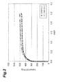
- the abscissa and ordinate of Fig. 2 are the same as in Fig. 1 .
- Activated coke was formed by the same method as in Comparative Example 1.
- the coke was vacuum dried at 120°C for 4 hours.
- a solution obtained by mixing the dried coke with 100 mg of LiOH and 30 mL of water was stirred for 4 hours for reaction between the coke and LiOH.
- the solution was subjected to suction filtration to filter out the solid, and the solid was rinsed 5 times with purified water.
- the rinsed solid was vacuum dried at 100°C for 4 hours to obtain a hydrogen storage material for Example 1.
- Example 1 The specific surface area, total pore volume and micropore volume of the hydrogen storage material of Example 1 were measured by the same method as Comparative Example 1. The measurement results are shown in Table 1. Fig. 1 also shows a nitrogen adsorption isotherm for Example 1.
- Table 1 BET specific surface area (m 2 /g) Total pore volume (cm 3 /g) Micropore volume (cm 3 /g) Comp. Ex. 1 2073 0.9808 0.9455 Example 1 1863 0.8760 0.8500
- Activated coke similar to Comparative Example 2 was vacuum dried at 120°C for 4 hours.
- a solution obtained by mixing the dried coke with 100 mg of LiOH and 30 mL of water was stirred for 4 hours for reaction between the coke and LiOH.
- the solution was subjected to suction filtration to filter out the solid, and the solid was rinsed 5 times with purified water.
- the rinsed solid was vacuum dried at 100°C for 4 hours to obtain a hydrogen storage material for Example 2.
- Example 2 The specific surface area, total pore volume and micropore volume of the hydrogen storage material of Example 2 were measured by the same method as Comparative Example 1. The measurement results are shown in Table 2. Fig. 2 also shows a nitrogen adsorption isotherm for Example 2.
- Example 1 The contents of the elements in the hydrogen storage material of Example 1 were determined by ICP emission analysis.
- the hydrogen storage materials of Example 2 and Comparative Examples 1 and 2 were also analyzed in the same manner as Example 1.
- the elemental analysis results are shown in Table 3.
- the analyzer used for analysis of K and Li was an ICPS-8100 by Shimadzu Corp.
- the analyzer used for analysis of C, H and N was a Vario EL III by Elementar.
- the analyzer used for analysis of O was an EA1110 by CE Instruments.
- the units for the content of each element shown in Table 3 are number of moles per gram of hydrogen storage material.
- the oxygen content of the hydrogen storage material of Example 1 was approximately the same as in Comparative Example 1. Also, the oxygen content of the hydrogen storage material of Example 2 was approximately the same as in Comparative Example 2.
- the hydrogen storage capacity of the hydrogen storage material of Example 1 was measured with the section of a sample tube containing the hydrogen storage material of Example 1 immersed in a 303K water tank.
- the hydrogen storage capacity was measured using a hydrogen storage capacity measuring apparatus by Rhesca Corp.
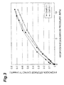
- the relationship between the hydrogen equilibrium pressure at 303K and the hydrogen storage capacity of Example 1 is shown in Fig. 3 .
- Table 4 shows the hydrogen storage capacity of Example 1 with a temperature of 303K and a hydrogen equilibrium pressure of 10 MPa.
- the hydrogen storage capacity of each of the hydrogen storage materials of Example 2, Comparative Example 1 and Comparative Example 2 was measured by the same method as in Example 1.
- the relationship between the hydrogen equilibrium pressure at 303K and the hydrogen storage capacity of Comparative Example 1 is shown in Fig. 3 .
- the relationships between the hydrogen equilibrium pressure at 303K and the hydrogen storage capacities of Example 2 and Comparative Example 2 are shown in Fig. 4 .
- Table 4 shows the hydrogen storage capacity of each of the hydrogen storage materials of Example 2, Comparative Example 1 and Comparative Example 2, with a temperature of 303K and a hydrogen equilibrium pressure of 10 MPa.
- the hydrogen storage capacities shown in Table 4 are the ratios of the mass of hydrogen stored in each hydrogen storage material with respect to the mass of the hydrogen storage material.
- Example 1 By comparing Example 1 and Comparative Example 1 it was confirmed that hydrogen storage capacity is increased by introducing Li into activated coke. Also, since the hydrogen storage capacity of Example 1 was greater than Comparative Example 1, despite a smaller specific surface area in Example 1 compared to Comparative Example 1, this confirmed that the hydrogen storage capacity of Example 1 depends not only on simple physical adsorption but also on strong interaction between the introduced Li and the hydrogen. The same conclusion is also obtained by comparing Example 2 with Comparative Example 2.
- the present invention can be used as a hydrogen storage material with more excellent hydrogen storage capacity than the prior art.
Landscapes
- Chemical & Material Sciences (AREA)
- Organic Chemistry (AREA)
- Engineering & Computer Science (AREA)
- Inorganic Chemistry (AREA)
- Chemical Kinetics & Catalysis (AREA)
- Nanotechnology (AREA)
- Analytical Chemistry (AREA)
- Materials Engineering (AREA)
- Combustion & Propulsion (AREA)
- Condensed Matter Physics & Semiconductors (AREA)
- Composite Materials (AREA)
- General Physics & Mathematics (AREA)
- Crystallography & Structural Chemistry (AREA)
- Life Sciences & Earth Sciences (AREA)
- Environmental & Geological Engineering (AREA)
- General Life Sciences & Earth Sciences (AREA)
- Geology (AREA)
- Physics & Mathematics (AREA)
- Hydrogen, Water And Hydrids (AREA)
- Solid-Sorbent Or Filter-Aiding Compositions (AREA)
- Carbon And Carbon Compounds (AREA)
Abstract
Description
- The present invention relates to a hydrogen storage material.
- Hydrogen is widely used in many industrial fields including petroleum refining and chemical engineering, but especially in recent years it has become noted as a future energy source, and research is being conducted with particular emphasis on fuel cells. However, hydrogen gas has high volume per quantity of heat, as well as high energy requirement for liquefaction, which poses the problem that its storage and transport in that form have been difficult (see Non-patent
document 1, for example). Techniques are therefore being sought for efficient transport and storage of hydrogen, when fuel cells are to be used in vehicles such as fuel cell automobiles or as distributed power sources. - One method that has been proposed is to use hydrogen in the form of liquid hydrogen for storage and transport, but since the liquefaction temperature is a cryogenic temperature of -253°C it is difficult to handle, and massive energy is required for liquefaction, thus lowering the overall energy efficiency (see Non-patent
document 2, for example). - Methods of using hydrogen as a high-pressure gas for transport are also being implemented. Such methods, however, entail problems such as requiring the handling of dangerous high-pressure gas, with a very large the volume even at the extremely high pressure of 35 MPa, making it difficult to achieve small sizes (see Non-patent document 3, for example).
- One powerfully effective method is storage in hydrogen storage alloys. However, the hydrogen storage capacity of hydrogen storage alloys is usually about 3%, which is not only insufficient for use in vehicles and the like, but also results in excessively increased weight. Hydrogen storage alloys also have reduced energy efficiency because of the need for large amounts of heat during hydrogen desorption, while the system also becomes complicated (see Non-patent document 4, for example).
- The use of hydrogen storage materials is also considered as a means of transporting hydrogen gas in a compact manner (see Patent document 1). Because this method allows hydrogen desorption to be accomplished at ordinary temperature and thus simplifies the system, while it generally does not require heat for hydrogen desorption and thus has high energy efficiency, the development of such materials is being actively pursued. It has also been reported that materials such as carbon nanotubes and carbon nanofibers exhibit high storage capacity (see Non-patent
document 5, for example). However, their reproducibility is in question, and at the current time it cannot be said that the development of hydrogen storage materials with sufficient reproducibility and high storage capacity has been achieved. - A demand therefore exists for development of materials with high storage capacity, and hence materials with fine pore sizes of the same level as hydrogen are being studied as materials with high storage capacity. Examples of such materials include the aforementioned carbon nanotubes and carbon nanofibers, but also other primarily carbon-based materials. Materials other than carbon have also been reported, including boron nitride nanotubes (Non-patent document 6) and porous complexes (Non-patent document 7). However, despite reports of some materials exhibiting high storage capacity, the currently available data is not sufficiently reliable.
- [Patent document 1] Japanese Patent Public Inspection No.
2007-529404 -
- [Non-patent document 1] Kobayashi, "Journal of the Institute of Applied Energy, Japan", Vol.25, No. 4, 2003, p.73-87
- [Non-patent document 2] Kuriyama, "Energy Resources", Vol.24, No. 6, 2003, p.23-27
- [Non-patent Document 3] Akiyama et al., "Engine Technology", Vol.5, No. 3, 2003, p.43-47
- [Non-patent Document 4] Akiba, "Engine Technology", Vol.5, No. 3, 2003, pp.36-42
- [Non-patent Document 5] A. Chambers et al., "Journal of Physical Chemistry B (J. Phys. Chem. B)" (US) Vol.102 1998, p.4253-4256
- [Non-patent Document 6] Renzhi Ma et al., "Journal of American Chemical Society (J. Am. Chem. Soc.)" (US), Vol.124, 2002, p.7672-7673
- [Non-patent Document 7] Nathaniel L. Rosi et al., "Science" (UK), Vol.300, 2003, p.1127-1129
- With the increasing availability of hydrogen in recent years, further improvements are desired in the hydrogen storage capacity of hydrogen storage materials. One method of increasing hydrogen storage capacity is to increase the specific surface area of the hydrogen storage material, thereby increasing the amount of hydrogen that is physically adsorbed on the surface of the hydrogen storage material. However, simply increasing the amount of physical adsorption of hydrogen does not allow the desired hydrogen storage capacity to be easily achieved.
- It is an object of the present invention, which has been accomplished in light of the aforementioned problems of the prior art, to provide a hydrogen storage material with more excellent hydrogen storage capacity than the prior art.
- In order to achieve the object stated above, the hydrogen storage material of the invention comprises a porous carbon material having oxygen-containing functional groups on the surface, and Li bonded to the surface of the porous carbon material. For the purpose of the invention, the "surface of the porous carbon material" includes the inner walls of the pores of the porous carbon material.
- Since the hydrogen storage material of the invention comprises Li which has high affinity with hydrogen, it has more excellent hydrogen storage capacity compared to conventional hydrogen storage materials composed of carbon materials.
- According to the invention, the oxygen-containing functional groups are preferably of at least one type selected from the group consisting of a phenolic hydroxyl group, a quinone group, a carboxyl group and a lactonic carboxyl groups group. This facilitates bonding of Li to the surface of the porous carbon material, so that the effect of the invention can be more notably exhibited.
- According to the invention, the porous carbon material is preferably activated coke. This will allow the effect of the invention to be exhibited more notably.
- According to the invention it is possible to provide a hydrogen storage material with more excellent hydrogen storage capacity than the prior art.
-
-
Fig. 1 is a nitrogen adsorption isotherm for the hydrogen storage materials of Example 1 of the invention and Comparative Example 1. -
Fig. 2 is a nitrogen adsorption isotherm for the hydrogen storage materials of Example 2 of the invention and Comparative Example 2. -
Fig. 3 is a graph showing the relationship between hydrogen storage capacity and equilibrium pressure of hydrogen at 303K, for the hydrogen storage materials of Example 1 of the invention and Comparative Example 1. -
Fig. 4 is a graph showing the relationship between hydrogen storage capacity and equilibrium pressure of hydrogen at 303K, for the hydrogen storage materials of Example 2 of the invention and Comparative Example 2. - Preferred embodiments of the invention will now be described in detail. The hydrogen storage material of this embodiment comprises a porous carbon material. Oxygen-containing functional groups are formed on the surface of the porous carbon material, and Li is bonded thereto. Most preferably, oxygen-containing functional groups are formed on the inner wall surfaces of the micropores of the porous carbon material, and Li bonds to the inner wall surfaces of the micropores of the porous carbon material. This notably increases the hydrogen storage capacity.
- The porous carbon material is preferably activated coke, and more preferably it is coke from which K has been removed, after activation by heating with KOH. The coke used may be petroleum coke or coal-derived coke. Other types of common active carbon may also be used as the porous carbon material.
- The oxygen-containing functional groups are preferably of at least one type selected from the group consisting of a phenolic hydroxyl group, a quinone group, a lactonic carboxyl group and a carboxyl group.
- Chemical Formula (1) below shows an example of a portion of the surface of the porous carbon material and the structure of a phenolic hydroxyl group formed on the surface.


- Chemical Formula (2) below shows an example of a portion of the surface of the porous carbon material and the structure of a quinone group formed on the surface.

- Chemical Formula (3) below shows an example of a portion of the surface of the porous carbon material and the structure of a lactonic carboxyl group formed on the surface.

- Chemical Formula (4) below shows an example of a portion of the surface of the porous carbon material and the structure of a carboxyl group formed on the surface.


- Chemical Formula (5) below shows a state in which Li is not bonded to part of the surface of the porous carbon material wherein carboxyl groups and hydroxyl groups are formed as oxygen-containing functional groups. Chemical Formula (6) below shows a state in which Li is bonded to part of the surface of the porous carbon material shown in Chemical Formula (5).


- As shown in Chemical Formulas (5) and (6), Li is preferably bonded to oxygen in the oxygen-containing functional groups, forming LiO groups. The LiO groups have a property of powerfully adsorbing hydrogen molecules. Thus, formation of LiO groups on the surface of the porous carbon material increases the adsorption density of hydrogen molecules in the hydrogen storage material, notably improving hydrogen storage capacity over the prior art.
- The oxygen-containing functional groups are most preferably phenolic hydroxyl groups, among the functional groups mentioned above. For increased hydrogen storage capacity, Li bonded to phenolic hydroxyl groups is preferred over Li bonded to other oxygen-containing functional groups.
- The specific surface area of the hydrogen storage material is preferably 500 m2/g or greater, and more preferably 1000 m2/g or greater. A hydrogen storage material with a high specific surface area of the hydrogen storage material may have a value of, for example, about 4000 m2/g. However, the specific surface area of the hydrogen storage material is not limited to these values. Since a larger specific surface area is associated with increased hydrogen storage capacity, a larger specific surface area is preferred. The specific surface area of the hydrogen storage material may be evaluated by the BET method.
- The amount of Li in the hydrogen storage material may be about 0.1-3 mmol/g. However, the amount of Li in the hydrogen storage material is not limited to this range. A larger amount of Li introduced into the hydrogen storage material increases the hydrogen storage capacity, and therefore a larger amount of Li introduction is preferred.
- A method for producing a hydrogen storage material using KOH-activated coke as the porous carbon material will now be below described.
- First, the coke is activated to form a porous carbon material. For this embodiment, preferably a mixture of coke and KOH is heat-treated. This forms oxygen-containing functional groups on the surface of the coke. Next, the heated coke is stirred with water, and this is repeatedly alternated with filtration for rinsing of the coke. After stirring the rinsed coke with hydrochloric acid, the stirring of coke and water is again repeatedly alternated with filtration for rinsing of the coke. This series of steps inactivates and removes the potassium remaining on the surface of the coke that has been heated with KOH. Porous coke activated by oxygen-containing functional groups is thus obtained. For this embodiment, the coke is preferably not calcined again after the oxygen-containing functional groups have been formed on the surface by heating with KOH. If the coke is calcined after the oxygen-containing functional groups have been formed on the surface, the oxygen dissociates from the oxygen-containing functional groups, tending to result in loss of oxygen-containing functional groups.
- By reacting activated coke with a Li reagent, Li is introduced into the coke, obtaining a hydrogen storage material according to this embodiment. The Li reagent used may be a Li salt aqueous solution or an organic Li solution. The Li agent used may be a Li2CO3 aqueous solution, LiOH aqueous solution, n-butyllithium/hexane solution, methyllithium/diethyl ether solution or lithium diisopropylamide-THF/ethylbenzene/heptane solution, and a LiOH aqueous solution is preferably used. The activated coke is dispersed in the Li salt aqueous solution, and the mixture is stirred at between room temperature and 100°C to introduce the Li into the coke. The concentration of the Li salt aqueous solution may be adjusted to about 0.1-1 M. The amount of Li in the Li salt aqueous solution is preferably 1-10 equivalents, and more preferably 4 equivalents, with respect to the oxygen-containing functional groups formed on the surface of the activated coke.
- A preferred embodiment of the hydrogen storage material of the invention and a method for producing it was described in detail above, but the invention is not limited to this embodiment. For example, coke activated with water vapor, CO2 or NaOH instead of KOH may be used as the porous carbon material. This will also allow the effect of the invention to be achieved, similar to the described embodiment.
- The present invention will now be below explained in greater detail based on examples and comparative examples, with the understanding that the invention is in no way limited to the examples.
- After mixing KOH in an amount of 2 equivalents with respect to petroleum coke (based on mass), heat treatment was conducted for 1 hour in a nitrogen gas atmosphere at 750°C, to obtain the activated product.
- A rinsing procedure was repeated twice, comprising a step of adding water at 100 equivalents with respect to the activated product (based on mass) and stirring for 1 hour, and a step of filtering the stirred activated product. Next, 0.1N hydrochloric acid was added at 100 equivalents with respect to the rinsed activated product (based on mass), and the mixture was stirred for 1 hour and filtered, after which the same rinsing procedure described above was carried out. This series of steps inactivated and removed the potassium remaining on the surface of the activated product, to obtain activated coke. This activated coke will hereunder also be referred to as "hydrogen storage material of Comparative Example 1".
- The activated coke was dispersed in a sodium hydroxide aqueous solution, in a sodium hydrogencarbonate aqueous solution and in aqueous sodium carbonate, and reacted, and then the bases remaining on the coke surface were back titrated with hydrochloric acid. The back titration allowed determination of the types of oxygen-containing functional groups present on the surface of the activated coke. The oxygen-containing functional groups on the surface of the activated coke were confirmed to consist of a quinone group, a hydroxyl group, a lactonic carboxyl group and a carboxyl group. In addition, the proportion of each of the functional groups with respect to the total oxygen-containing functional groups was also determined by back titration. The proportions of a quinone group, a hydroxyl group, a lactonic carboxyl group and a carboxyl group were confirmed to be approximately 30 mol%, 45 mol%, 20 mol% and 5 mol%, respectively.
- The BET specific surface area, total pore volume and micropore volume of the hydrogen storage material of Comparative Example 1 were measured by the nitrogen adsorption method. The measurement results are shown in Table 1.
Fig. 1 shows a nitrogen adsorption isotherm for Comparative Example 1. The ratio p/p0 on the abscissa ofFig. 1 is the ratio of the nitrogen gas partial pressure p and the nitrogen gas vapor pressure p0. The units Va/cm3 (STP)/g on the ordinate ofFig. 1 are the volume of nitrogen gas adsorbed onto a 1 g unit mass of the hydrogen storage material, under standard conditions. The abscissa and ordinate ofFig. 2 are the same as inFig. 1 . - Activated coke was formed by the same method as in Comparative Example 1. The coke was vacuum dried at 120°C for 4 hours. A solution obtained by mixing the dried coke with 100 mg of LiOH and 30 mL of water was stirred for 4 hours for reaction between the coke and LiOH. Upon completion of the reaction, the solution was subjected to suction filtration to filter out the solid, and the solid was rinsed 5 times with purified water. The rinsed solid was vacuum dried at 100°C for 4 hours to obtain a hydrogen storage material for Example 1.
- The specific surface area, total pore volume and micropore volume of the hydrogen storage material of Example 1 were measured by the same method as Comparative Example 1. The measurement results are shown in Table 1.
Fig. 1 also shows a nitrogen adsorption isotherm for Example 1. - [Table 1]
Table 1 BET specific surface area (m2/g) Total pore volume (cm3/g) Micropore volume (cm3/g) Comp. Ex. 1 2073 0.9808 0.9455 Example 1 1863 0.8760 0.8500 - Activated coke was prepared as a hydrogen storage material for Comparative Example 2. As a result of back titration in the same manner as Comparative Example 1, it was confirmed that a quinone group, a hydroxyl group, a lactonic carboxyl group and a carboxyl group had been formed on the surface of the coke of Comparative Example 2.
- The specific surface area, total pore volume and micropore volume of the hydrogen storage material of Comparative Example 2 were measured by the same method as Comparative Example 1. The measurement results are shown in Table 2.
Fig. 2 shows a nitrogen adsorption isotherm for Comparative Example 2. - Activated coke similar to Comparative Example 2 was vacuum dried at 120°C for 4 hours. A solution obtained by mixing the dried coke with 100 mg of LiOH and 30 mL of water was stirred for 4 hours for reaction between the coke and LiOH. Upon completion of the reaction, the solution was subjected to suction filtration to filter out the solid, and the solid was rinsed 5 times with purified water. The rinsed solid was vacuum dried at 100°C for 4 hours to obtain a hydrogen storage material for Example 2.
- The specific surface area, total pore volume and micropore volume of the hydrogen storage material of Example 2 were measured by the same method as Comparative Example 1. The measurement results are shown in Table 2.
Fig. 2 also shows a nitrogen adsorption isotherm for Example 2. - [Table 2]
Table 2 BET specific surface area (m2/g) Total pore volume (cm3/g) Micropore volume (cm3/g) Comp. Ex. 2 1659 0.7821 0.7414 Example 2 1585 0.7344 0.6945 - The contents of the elements in the hydrogen storage material of Example 1 were determined by ICP emission analysis. The hydrogen storage materials of Example 2 and Comparative Examples 1 and 2 were also analyzed in the same manner as Example 1. The elemental analysis results are shown in Table 3. The analyzer used for analysis of K and Li was an ICPS-8100 by Shimadzu Corp. The analyzer used for analysis of C, H and N was a Vario EL III by Elementar. The analyzer used for analysis of O was an EA1110 by CE Instruments. The units for the content of each element shown in Table 3 are number of moles per gram of hydrogen storage material.
- [Table 3]
Table 3 Element K Li C H N O Atomic mass 39.1 6.94 12.0 1.0 14.0 16.0 Content (mmol/g) Comp. Ex. 1 0.00 0.00 75.7 5.0 0 3.5 Example 1 0.00 0.43 72.2 8.0 0 - Comp. Ex. 2 0.00 0.00 75.8 7.0 0 3.5 Example 2 0.00 0.36 73.8 8.0 0 - - The oxygen content of the hydrogen storage material of Example 1 was approximately the same as in Comparative Example 1. Also, the oxygen content of the hydrogen storage material of Example 2 was approximately the same as in Comparative Example 2.
- The hydrogen storage capacity of the hydrogen storage material of Example 1 was measured with the section of a sample tube containing the hydrogen storage material of Example 1 immersed in a 303K water tank. The hydrogen storage capacity was measured using a hydrogen storage capacity measuring apparatus by Rhesca Corp. The relationship between the hydrogen equilibrium pressure at 303K and the hydrogen storage capacity of Example 1 is shown in
Fig. 3 . Also, Table 4 shows the hydrogen storage capacity of Example 1 with a temperature of 303K and a hydrogen equilibrium pressure of 10 MPa. - The hydrogen storage capacity of each of the hydrogen storage materials of Example 2, Comparative Example 1 and Comparative Example 2 was measured by the same method as in Example 1. The relationship between the hydrogen equilibrium pressure at 303K and the hydrogen storage capacity of Comparative Example 1 is shown in
Fig. 3 . The relationships between the hydrogen equilibrium pressure at 303K and the hydrogen storage capacities of Example 2 and Comparative Example 2 are shown inFig. 4 . Also, Table 4 shows the hydrogen storage capacity of each of the hydrogen storage materials of Example 2, Comparative Example 1 and Comparative Example 2, with a temperature of 303K and a hydrogen equilibrium pressure of 10 MPa. The hydrogen storage capacities shown in Table 4 are the ratios of the mass of hydrogen stored in each hydrogen storage material with respect to the mass of the hydrogen storage material. - [Table 4]
Table 4 Hydrogen storage capacity (mass%) Comp. Ex. 1 0.647 Example 1 0.706 Comp. Ex. 2 0.490 Example 2 0.575 - By comparing Example 1 and Comparative Example 1 it was confirmed that hydrogen storage capacity is increased by introducing Li into activated coke. Also, since the hydrogen storage capacity of Example 1 was greater than Comparative Example 1, despite a smaller specific surface area in Example 1 compared to Comparative Example 1, this confirmed that the hydrogen storage capacity of Example 1 depends not only on simple physical adsorption but also on strong interaction between the introduced Li and the hydrogen. The same conclusion is also obtained by comparing Example 2 with Comparative Example 2.
- The present invention can be used as a hydrogen storage material with more excellent hydrogen storage capacity than the prior art.
Claims (3)
- A hydrogen storage material comprising:a porous carbon material having oxygen-containing functional groups on the surface, andLi bonded to the surface of the porous carbon material.
- The hydrogen storage material according to claim 1,
wherein the oxygen-containing functional groups are of at least one type selected from the group consisting of a phenolic hydroxyl group, a quinone group, a carboxyl group and a lactonic carboxyl group. - The hydrogen storage material according to claim 1 or 2,
wherein the porous carbon material is activated coke.
Applications Claiming Priority (2)
| Application Number | Priority Date | Filing Date | Title |
|---|---|---|---|
| JP2009238396A JP5653025B2 (en) | 2009-10-15 | 2009-10-15 | Hydrogen storage material |
| PCT/JP2010/065852 WO2011046001A1 (en) | 2009-10-15 | 2010-09-14 | Hydrogen storage material |
Publications (2)
| Publication Number | Publication Date |
|---|---|
| EP2489633A1 true EP2489633A1 (en) | 2012-08-22 |
| EP2489633A4 EP2489633A4 (en) | 2016-06-08 |
Family
ID=43876055
Family Applications (1)
| Application Number | Title | Priority Date | Filing Date |
|---|---|---|---|
| EP10823269.5A Withdrawn EP2489633A4 (en) | 2009-10-15 | 2010-09-14 | HYDROGEN STORAGE MATERIAL |
Country Status (4)
| Country | Link |
|---|---|
| US (1) | US8980788B2 (en) |
| EP (1) | EP2489633A4 (en) |
| JP (1) | JP5653025B2 (en) |
| WO (1) | WO2011046001A1 (en) |
Families Citing this family (3)
| Publication number | Priority date | Publication date | Assignee | Title |
|---|---|---|---|---|
| JP5728203B2 (en) * | 2010-11-17 | 2015-06-03 | Jx日鉱日石エネルギー株式会社 | Hydrogen storage material |
| JP5623879B2 (en) * | 2010-11-17 | 2014-11-12 | Jx日鉱日石エネルギー株式会社 | Hydrogen storage material |
| CN118419854B (en) * | 2024-04-22 | 2024-12-17 | 山东大学 | Magnesium@high-sulfur coke hydrogen storage material and preparation method thereof |
Family Cites Families (12)
| Publication number | Priority date | Publication date | Assignee | Title |
|---|---|---|---|---|
| US4082694A (en) | 1975-12-24 | 1978-04-04 | Standard Oil Company (Indiana) | Active carbon process and composition |
| CA1071177A (en) * | 1975-12-24 | 1980-02-05 | Standard Oil Company | Active carbon process and composition |
| FR2553676B1 (en) * | 1983-10-25 | 1986-02-07 | France Etat Armement | ACTIVE CARBON IMPREGNATED FOR THE FILTRATION OF CYANOGENIC HALIDES AND METHODS OF PREPARATION |
| JPS6261529A (en) | 1985-09-13 | 1987-03-18 | 石倉 建治 | Concrete block |
| JPS62191040A (en) * | 1986-02-17 | 1987-08-21 | Nippon Denso Co Ltd | Adsorbable carbon material and its production |
| JPH0834605A (en) * | 1994-07-26 | 1996-02-06 | Kansai Coke & Chem Co Ltd | Adsorbent for water purification |
| JP2002028483A (en) * | 2000-07-13 | 2002-01-29 | Toyota Central Res & Dev Lab Inc | Hydrogen gas storage material |
| JP2003225563A (en) * | 2002-02-04 | 2003-08-12 | Toyota Central Res & Dev Lab Inc | Carbon material for hydrogen storage, method for producing the same, and hydrogen storage device using the same |
| JP2005129722A (en) * | 2003-10-23 | 2005-05-19 | Nippon Oil Corp | Electric double layer capacitor, activated carbon for the electrode, and manufacturing method thereof |
| WO2005090486A2 (en) | 2004-03-15 | 2005-09-29 | Cabot Corporation | Surface modified carbon products and their applications |
| JP2007320799A (en) * | 2006-05-31 | 2007-12-13 | Nippon Oil Corp | Hydrogen storage carbon |
| JP5288592B2 (en) * | 2008-06-03 | 2013-09-11 | 俊則 國府 | Method for producing high specific surface area activated carbon |
-
2009
- 2009-10-15 JP JP2009238396A patent/JP5653025B2/en not_active Expired - Fee Related
-
2010
- 2010-09-14 US US13/501,538 patent/US8980788B2/en not_active Expired - Fee Related
- 2010-09-14 EP EP10823269.5A patent/EP2489633A4/en not_active Withdrawn
- 2010-09-14 WO PCT/JP2010/065852 patent/WO2011046001A1/en not_active Ceased
Non-Patent Citations (1)
| Title |
|---|
| See references of WO2011046001A1 * |
Also Published As
| Publication number | Publication date |
|---|---|
| EP2489633A4 (en) | 2016-06-08 |
| US8980788B2 (en) | 2015-03-17 |
| WO2011046001A1 (en) | 2011-04-21 |
| JP2011084432A (en) | 2011-04-28 |
| US20120215013A1 (en) | 2012-08-23 |
| JP5653025B2 (en) | 2015-01-14 |
Similar Documents
| Publication | Publication Date | Title |
|---|---|---|
| Duan et al. | Metal‐free carbon materials for CO2 electrochemical reduction | |
| Kang et al. | Hydrogen adsorption on nitrogen-doped carbon xerogels | |
| US7723262B2 (en) | Activated carbon cryogels and related methods | |
| Huang et al. | Effect of surface oxides on hydrogen storage of activated carbon | |
| US8657923B2 (en) | Microporous carbon material, manufacturing method thereof, and hydrogen storage method using microporous carbon material | |
| JP5835787B2 (en) | Microporous carbon material, method for producing microporous carbon material, and hydrogen storage method using microporous carbon material | |
| US8569206B2 (en) | Porous carbon material and a method of production thereof | |
| Wang et al. | Porous manganese–cobalt oxide microspheres with tunable oxidase mimicking activity for sulfide ion colorimetric detection | |
| Zhang et al. | Porosity engineering of biochar‐based single‐atom Ni catalysts to promote CO2 electroreduction over a broad potential window | |
| Peluso et al. | Modeling hydrogen sulfide adsorption on chromium-based MIL-101 metal organic framework | |
| US8980788B2 (en) | Hydrogen storage material | |
| KR20220010861A (en) | Manufacturing method of activated carbon derived from coconut shells by chemical activation and silica elimination for hydrogen storage | |
| CN116832790B (en) | Application of a solid amine low-temperature carbon capture material in low-temperature CO2 adsorption | |
| JP2018047453A (en) | Spherical phenol resin activated carbon for methane occlusion and method for producing the same, and methane occlusion material using activated carbon and methane occlusion method using activated carbon | |
| Phuong et al. | Synthesis of metal organic framework based on Cu and benzene‐1, 3, 5‐tricarboxylic acid (H3BTC) by potentiodynamic method for CO2 adsorption | |
| JP5623879B2 (en) | Hydrogen storage material | |
| Shekarabi et al. | Experimental and theoretical investigation of glucose–graphene hybrid for increasing the natural gas storage | |
| CN107955182B (en) | Micro-doped composite metal organic framework material, preparation method and application thereof | |
| Lin et al. | Hydrogen adsorption in metal organic frameworks by hydrogen spillover | |
| CN116103686B (en) | In single-atom catalyst, preparation method and application thereof | |
| JP5728203B2 (en) | Hydrogen storage material | |
| Wang et al. | Nitrogen, phosphorus co-doped carbon dots/CoS 2 hybrid for enhanced electrocatalytic hydrogen evolution reaction | |
| US12410530B1 (en) | Method of making a metal-N/S-doped carbon electrocatalyst | |
| Zhong et al. | Synthesis of a carbon nanotube and carbon sphere coexisting catalyst for enhanced oxygen reduction reaction and its applications | |
| JP5010805B2 (en) | Method for heat treatment of metal-organic framework |
Legal Events
| Date | Code | Title | Description |
|---|---|---|---|
| PUAI | Public reference made under article 153(3) epc to a published international application that has entered the european phase |
Free format text: ORIGINAL CODE: 0009012 |
|
| 17P | Request for examination filed |
Effective date: 20120510 |
|
| AK | Designated contracting states |
Kind code of ref document: A1 Designated state(s): AL AT BE BG CH CY CZ DE DK EE ES FI FR GB GR HR HU IE IS IT LI LT LU LV MC MK MT NL NO PL PT RO SE SI SK SM TR |
|
| DAX | Request for extension of the european patent (deleted) | ||
| RA4 | Supplementary search report drawn up and despatched (corrected) |
Effective date: 20160511 |
|
| RIC1 | Information provided on ipc code assigned before grant |
Ipc: B82Y 30/00 20110101ALI20160504BHEP Ipc: C01B 3/00 20060101ALI20160504BHEP Ipc: B01J 20/20 20060101ALI20160504BHEP Ipc: C01B 31/12 20060101AFI20160504BHEP Ipc: B01J 20/32 20060101ALI20160504BHEP Ipc: C01B 31/08 20060101ALI20160504BHEP |
|
| STAA | Information on the status of an ep patent application or granted ep patent |
Free format text: STATUS: THE APPLICATION IS DEEMED TO BE WITHDRAWN |
|
| 18D | Application deemed to be withdrawn |
Effective date: 20161210 |