EP2489540A1 - Vehicle instrument panel structure - Google Patents
Vehicle instrument panel structure Download PDFInfo
- Publication number
- EP2489540A1 EP2489540A1 EP10823308A EP10823308A EP2489540A1 EP 2489540 A1 EP2489540 A1 EP 2489540A1 EP 10823308 A EP10823308 A EP 10823308A EP 10823308 A EP10823308 A EP 10823308A EP 2489540 A1 EP2489540 A1 EP 2489540A1
- Authority
- EP
- European Patent Office
- Prior art keywords
- lid
- instrument panel
- contact
- protrusion
- engaged
- Prior art date
- Legal status (The legal status is an assumption and is not a legal conclusion. Google has not performed a legal analysis and makes no representation as to the accuracy of the status listed.)
- Granted
Links
Images


Classifications
-
- B—PERFORMING OPERATIONS; TRANSPORTING
- B60—VEHICLES IN GENERAL
- B60R—VEHICLES, VEHICLE FITTINGS, OR VEHICLE PARTS, NOT OTHERWISE PROVIDED FOR
- B60R13/00—Elements for body-finishing, identifying, or decorating; Arrangements or adaptations for advertising purposes
- B60R13/02—Internal Trim mouldings ; Internal Ledges; Wall liners for passenger compartments; Roof liners
- B60R13/0275—Internal Trim mouldings ; Internal Ledges; Wall liners for passenger compartments; Roof liners comprising removable or hinged parts
-
- B—PERFORMING OPERATIONS; TRANSPORTING
- B60—VEHICLES IN GENERAL
- B60K—ARRANGEMENT OR MOUNTING OF PROPULSION UNITS OR OF TRANSMISSIONS IN VEHICLES; ARRANGEMENT OR MOUNTING OF PLURAL DIVERSE PRIME-MOVERS IN VEHICLES; AUXILIARY DRIVES FOR VEHICLES; INSTRUMENTATION OR DASHBOARDS FOR VEHICLES; ARRANGEMENTS IN CONNECTION WITH COOLING, AIR INTAKE, GAS EXHAUST OR FUEL SUPPLY OF PROPULSION UNITS IN VEHICLES
- B60K35/00—Instruments specially adapted for vehicles; Arrangement of instruments in or on vehicles
- B60K35/50—Instruments characterised by their means of attachment to or integration in the vehicle
-
- B—PERFORMING OPERATIONS; TRANSPORTING
- B60—VEHICLES IN GENERAL
- B60K—ARRANGEMENT OR MOUNTING OF PROPULSION UNITS OR OF TRANSMISSIONS IN VEHICLES; ARRANGEMENT OR MOUNTING OF PLURAL DIVERSE PRIME-MOVERS IN VEHICLES; AUXILIARY DRIVES FOR VEHICLES; INSTRUMENTATION OR DASHBOARDS FOR VEHICLES; ARRANGEMENTS IN CONNECTION WITH COOLING, AIR INTAKE, GAS EXHAUST OR FUEL SUPPLY OF PROPULSION UNITS IN VEHICLES
- B60K37/00—Dashboards
-
- B—PERFORMING OPERATIONS; TRANSPORTING
- B60—VEHICLES IN GENERAL
- B60K—ARRANGEMENT OR MOUNTING OF PROPULSION UNITS OR OF TRANSMISSIONS IN VEHICLES; ARRANGEMENT OR MOUNTING OF PLURAL DIVERSE PRIME-MOVERS IN VEHICLES; AUXILIARY DRIVES FOR VEHICLES; INSTRUMENTATION OR DASHBOARDS FOR VEHICLES; ARRANGEMENTS IN CONNECTION WITH COOLING, AIR INTAKE, GAS EXHAUST OR FUEL SUPPLY OF PROPULSION UNITS IN VEHICLES
- B60K2360/00—Indexing scheme associated with groups B60K35/00 or B60K37/00 relating to details of instruments or dashboards
- B60K2360/60—Structural details of dashboards or instruments
- B60K2360/68—Features of instruments
- B60K2360/682—Arrangements to cover or hide instruments
Definitions
- the present invention relates to a vehicle instrument panel structure, and particularly relates to a structure for prevention of drop-off of a lid removably provided on an instrument panel.
- an instrument panel disposed anterior to a vehicle interior is provided with various instruments on the front side, and is provided with many components, such as a fuse, on the inside of the vehicle that is the rear surface side of the instrument panel. Therefore, the instrument panel is provided with an opening portion for maintenance for replacement task on the fuse and the like arranged inside the vehicle, and is further provided with a lid for closing the opening portion for maintenance. Further, from the viewpoint of easy maintenance, for easy replacement of a fuse and the like, the below-described Patent Document 1 discloses a lid removable from an instrument panel, wherein the instrument panel is provided with an engagement hole, and the lid is provided with an engagement nail.
- the lid can be easily removed, the lid may easily drop off from the instrument panel.
- the opening portion for maintenance is provided near a foot of a passenger, as it is highly possible that the passenger unintentionally kicks or contact the lid, the lid may drop off from the instrument panel.
- an object of the invention is to provide a structure that enables easy removing a lid from an instrument panel and inhibits drop-off of the lid.
- a vehicle instrument panel structure having an opening portion for maintenance of components disposed inside an instrument panel for a vehicle and a lid covering the opening portion includes: a projection portion projecting from an upper portion of the lid to a rear surface side of a margin of the opening portion; and a protrusion portion at which the projection portion of the lid stops by engagement in a state that a lower portion of the lid is open on the rear surface side of the margin of the opening portion of the instrument panel, wherein the protrusion portion is formed such that, when the lid is moved downward in the state that the lower portion of the lid is open, the projection portion can move over the protrusion portion that stops the projection portion by engagement, and the lid can be thereby removed from the instrument panel.
- the projection portion of the lid can be supported on the rear surface side of the instrument panel. Further, when the lid is open, the projection portion formed on the lid stops by engagement at the protrusion portion formed on the margin of the opening portion. Accordingly, even when the lid is unintentionally kicked, as the projection portion of the lid stops by engagement at the protrusion portion, the lid cannot be separated from the instrument panel unless the projection portion of the lid moves over the protrusion portion. In such a manner, it does not occur that the lid easily separates from the instrument panel to drop off.
- the projection portion of the lid is stopped by engagement by the protrusion portion of the instrument panel, and by moving the lid further downward, the projection portion of the lid moves over the protrusion portion of the instrument panel and thereby the lid can be easily removed.
- a vehicle instrument panel structure having an opening portion for maintenance of components disposed inside an instrument panel for a vehicle and a lid covering the opening portion includes: a projection portion projecting from an upper portion of the lid to a rear surface side of a margin of the opening portion; and a protrusion portion at which the projection portion of the lid stops by engagement when the lid is moved downward in a state that a lower portion of the lid is open on the rear surface side of the margin of the opening portion of the instrument panel, wherein the protrusion portion is formed such that, when the lid is moved downward in the state that the lower portion of the lid is open, the projection portion can move over the protrusion portion that stops the projection portion, and the lid can be thereby removed from the instrument panel.
- the lid can be supported on the rear surface side of the instrument panel.
- the vehicle instrument panel structure is preferably arranged such that the projecting portion of the lid is provided with a contact-engaged portion that stops at the protrusion portion by engagement, and that the rear surface side of the margin of the opening portion of the instrument panel is provided with: a support portion for supporting the contact-engaged portion when the lid is open; an extension portion continuously extending downward from the support portion; and the protrusion portion that is protruding from a part of the extension portion.
- the lid can be supported by the instrument panel.
- the extension portion is provided, continuously extending from the support portion, when the lid in an open state is moved downward, the contact-engaged portion engaged in contact with the support portion slides along the extension portion, and the lid can thereby be removed.
- the protrusion portion is formed on the extension portion where the contact-engaged portion slides, the contact-engaged portion stops by engagement at the protrusion portion, and the lid cannot be separated from the instrument panel unless the contact-engaged portion moves over the protrusion portion at which the contact-engaged portion is engaged in contact.
- the vehicle instrument panel structure is preferably arranged such that the protrusion portion is formed in a vicinity of the support portion.
- the contact-engaged portion continues to be engaged in contact at the support portion unless the contact-engaged portion moves over the protrusion portion.
- the lid can thereby be stably supported.
- the vehicle instrument panel structure is preferably arranged such that an auxiliary panel for covering the margin of the opening portion is fitted on the instrument panel, and a gap between the protrusion portion and the auxiliary panel is set in a size that enables sandwiching the contact-engaged portion.
- the instrument panel structure for a vehicle in the present embodiment includes three members, namely, an instrument panel 10 as a main body, a lid 20 fitted on the instrument panel 10, and an auxiliary panel 40.
- the instrument panel 10 is a panel for supporting various meters, switches, audios, and the like, and is fitted to the vehicle body of a vehicle 1 such that various supported meters, switches, and the like face the inner side of a vehicle interior 2, as shown in FIG. 1 (a) . Further, as shown in FIG. 1 (a) , the instrument panel 10 is provided with an opening portion 11 on the left-lower side, and a lid 20 for closing the opening portion 11 is fitted.
- the opening portion 11 is a hole for replacement task on a fuse, not shown, fitted on the rear surface side of the instrument panel 10. As shown in FIGS. 1 and 2 , the opening portion 11 is provided on the lower surface 10a of the instrument panel 10. As shown in FIGS.
- the lower surface 10a is inclined such as to be closer to the vehicle front side as going downward. Accordingly, accompanying the lower surface 10a, the opening portion 11 is also an inclined hole such that the lower side is closer to the vehicle front side than the upper side. Further, the opening portion 11 is formed in a size that enables replacement of a fuse.
- the rear surface side of the instrument panel 10 refers to the vehicle body side where the instrument panel 10 is fitted, and the front surface side of the instrument panel 10 refers to the side facing the vehicle interior 2.
- the instrument panel 10 is, as shown in FIG. 3 , provided on the rear surface side with a marginal portion 30 for removably supporting the lid 20, and is provided on the rear surface side of the instrument panel 10 with an auxiliary panel 40.
- the lid 20, the marginal portion 30, and the auxiliary panel 40 will be described below in detail.
- the lid 20 is a lid member that is removably supported by the marginal portion 30 of the instrument panel 10, and closes the opening portion 11.
- the lid 20 has, as shown in FIG. 2 , a closing portion 21 for closing the opening portion 11, engagement portions 22 formed on the rear surface of the closing portion 21, and a projection portion 23 projecting from the upper side of the closing portion 21.
- the closing portion 21 is, as shown in FIG. 2 , in a plate shape corresponding to the size of the opening portion 11 that is closed, and is formed such as to be on the same plane as the front surface side of the instrument panel 10. Further, as shown in FIG. 2 , the engagement portions 22 are used for engagement, being engaged into the engagement holes 33 of the later-described marginal portion 3, in order that the closing portion 21 holds the opening portion 11 in a closed state.
- the engagement portions 22 are formed on the rear surface side of the closing portion 21 at positions corresponding to the engagement holes 33 of the marginal portion 30.
- the projection portion 23 is a portion that is supported by the marginal portion 30 formed on the rear surface of the instrument panel 10, and projects upward from the rear surface side of the closing portion 21.
- the projection portion 23 is, as shown in FIG. 2 , includes a contact-engaged portion 24 projecting along the lateral direction of the closing portion 21 and connection portions 25 for connecting the contact-engaged portion 24 and the closing portion 21.
- connection portions 25 extend from the rear surface upper portion of the closing portion 21 to the rear surface side and further extend from there, and are formed substantially in an L-shape in a side view (refer to FIG. 4 (a) and Fig. 4 (b) ). Further, as shown in FIG. 2 , when the lid 20 is viewed from the front side, the connection portions 25 include, a right side connection portion 25a disposed on the right side and a left side connection portion 25b disposed on the left side.
- the contact-engaged portion 24 when viewed from the front surface side of the closing portion 21, includes a right side contact-engaged portion 24a projecting from the right side surface of the right side connection portion 25a, a left side contact-engaged portion 24b projecting from the left side surface of the left side connection portion 25b, and a central contact-engaged portion 24c extending between the right side connection portion 25a and the left side connection portion 25b, along the lateral direction of the closing portion 21. Further, as shown in FIG.
- the length L1 from the end portion of the right side contact-engaged portion 24a to the end portion of the left side contact-engaged portion 24b is formed to be longer than the distance L2 between a right side support portion 31a and a left side support portion 31b of a support portion 31 of the marginal portion 30 described later.
- the distance between the right side support portion 31a and the left side support portion 31b of the support portion 31 and the distance between a right side extension portion 32a and a left side extension portion 32b of an extension portion 32 are formed to be the same, which will be described later.
- 'L2' shown in FIG. 2 represents the distance between the right side extension portion 32a of the extension portion 32 and the left side extension portion 32b.
- the right side contact-engaged portion 24a and the left side contact-engaged portion 24b are formed in a shape with which the right side contact-engaged portion 24a and the left side contact-engaged portion 24b can be stopped by engagement in contact with a protrusion portion 34 of the marginal portion 30, described later, and can slide on and move over the protrusion portion 34 in contact when the lid 20 is moved downward.
- the right side contact-engaged portion 24a and the left side contact-engaged portion 24b are formed in, for example, in a shape of a cylinder, a chamfered triangular prism, or the like.
- the right side contact-engaged portion 24a and the left side contact-engaged portion 24b are formed such as to have a thickness that is a little larger than the gap L3 (refer to FIG. 4 ) formed by the later-described protrusion portion 34 of the marginal portion 30 and the auxiliary panel 40.
- the central contact-engaged portion 24c is engaged in contact with a central support portion 31c of the support portion 31 described later, and is formed longer than the central support portion 31 with respect to the lateral direction.
- the shape and the like thereof is not particularly limited, however, with this arrangement, the lid 20 can be supported in a more stable state when the lid 20 is opened.
- the marginal portion 30 is, as shown in FIG. 3 , an element that removably supports the lid 20 for closing the opening portion 11, and is formed, on the rear surface side of the instrument panel 10, in the margin of the upper end side and in the margins of the left/right sides of the opening portion 11.
- the marginal portion 30 is, as shown in FIG. 3 and FIG. 4(a) , includes the support portion 31 for supporting the contact-engaged portion 24 of the lid 20, the extension portion 32 extending from the support portion 31 to the rear surface lower side, the engagement holes 33 penetrating the extension portion 32, and the protrusion portion 34 protruding from the extension portion 32 toward the rear surface upper side.
- the support portion 31 is a component for supporting the contact-engaged portion 24 formed at the projection portion 23 of the lid 20. As shown in FIG. 3 , corresponding to the right side contact-engaged portion 24a, the left side contact-engaged portion 24b, and the central contact-engaged portion 24c of the contact-engaged portion 24 of the lid 20, the support portion 31 includes the right side support portion 31a disposed on the right side, the left side support portion 31b disposed on the left side, and the central support portion 31c disposed at the center.
- the right side support portion 31a is, as shown in FIG. 4 (a) , extending from the upper end side of the opening portion 11 of the instrument panel 10 toward the vehicle front side and downward.
- the inclination angle of the right side support portion 31a is, as shown in FIG. 4 (a) , formed to an extent at which the right side contact-engaged portion 24a engaged in contact with the right side support portion 31a can slide to the right side extension portion 32a side by the own-weight of the lid 20.
- the contact-engaged portion 24 of the lid 20 can thereby be engaged in contact with the support portion 31, and slides toward the right side extension portion 32a side by the own-weight of the lid 20.
- the left side support portion 31b is also extending from the upper end side of the opening portion 11 of the instrument panel 10 toward the vehicle front side, with an angular inclination.
- the width L2 which is the distance between the right side support portion 31a and the left side support portion 31b, is formed smaller than the length L1 between the end portion of the right side contact-engaged portion 24a and the end portion of the left side contact-engaged portion 24b.
- the right side contact-engaged portion 24a and the left side contact-engaged portion 24b on the both end sides of the contact-engaged portion 24 can be engaged in contact respectively with the right side support portion 31a and the left side support portion 31b, wherein the both end sides of the lid 20 are supported by the support portion 31.
- the central support portion 31c is, as shown in FIG.
- the central support portion 31c extends from the upper end side of the opening portion 11 toward the rear surface side to an extent that the central support portion 31c can support the central contact-engaged portion 24c of the contact-engaged portion 24.
- the central support portion 31c is formed, as shown in FIG. 3 , shorter than the width of the central contact-engaged portion 24c.
- the support portion 31 is provided with respective notches between the right side support portion 31a, the central support portion 31 c, and the left side support portion 31b, wherein the connection portion 25 of the projection portion 23 of the lid 20 can pass the notches.
- connection portion 25 of the projection portion 23 of the lid 20 can pass the notches between the right side support portion 31a, the central support portion 31c, and the left side support portion 31b so that the contact-engaged portion 24 on the upper side of the projection portion 23 can be disposed upper than the support portion 31.
- the extension portion 32 is a portion for preventing drop-off of the lid 20 from the instrument panel 10 even in a case that the contact-engaged portion 24 of the lid 20 deviates from the support portion 31 to the rear surface side to lose support.
- the extension portion 32 as shown in FIGS. 2 and 3 , includes the right side extension portion 32a (refer to FIG. 4 (a) ) extending from the rear surface side end portion of the right side support portion 31a of the support portion 31 toward the rear surface lower side, and the left side extension portion 32b extending from the rear surface end portion of the left side support portion 31b toward the rear surface lower side.
- the distance between the right side extension portion 32a and the left side extension portion 32b is formed to be the same length as the distance L2 between the right side support portion 31a and the left side support portion 31b of the support portion 31.
- the right side contact-engaged portion 24a and the left side contact-engaged portion 24b stop the engagement so that the lid 20 can be removed from the instrument panel 10.
- the engagement holes 33 are, as shown in FIG. 2 and Fig. 4(a) , holes that the extension portion 32 penetrates, and are formed in a shape that enables engagement stop of the engagement portions 22 of the lid 20 by engaging of the engagement portions 22 into the engagement holes 33. Further, the engagement holes 33 are formed at positions that correspond to the engagement portions 22 formed on the rear surface side of the lid 20 when the opening portion 11 of the lid 20 is closed.
- the protrusion portion 34 includes, as shown in FIG. 3 , a right side protrusion portion 34a formed by protrusion of the upper surface side of the right side extension portion 32a in the vicinity of the right side support portion 31 a, and a left side protrusion portion 34b formed by protrusion of the upper surface side of the left side extension portion 32b in the vicinity of the left side support portion 31b.
- the right side protrusion portion 34a is, as shown in FIG. 4 (a) , formed in the vicinity of the right side support portion 31a. Accordingly, as shown in FIG.
- the contact-engaged portion 24a sliding along the right side support portion 31a, which is an inclined surface, to the right side extension portion 32a side comes in contact with the upper surface side of the right side protrusion portion 34a and stops by engagement.
- the right side protrusion portion 34a is, as shown in FIG. 4 (a) , formed in a shape with which the right side contact-engaged portion 24a can slide along and move over the right side protrusion portion 34a in contact when the lid 20 is moved downward.
- the right side protrusion portion 34a in the present embodiment is, as shown in FIG. 5 , protruding in a chamfered rectangular shape, however without being limited thereto, may be, for example, a protrusion in a half cylindrical shape.
- the left side protrusion portion 34b is formed in the vicinity of the left side support portion 31b, and is also formed in a shape with which the left side contact-engaged portion 24b can slide along and move over the left side protrusion portion 34b when the lid 20 is moved downward. Still further, the side surfaces on the lower sides of the right side protrusion portion 34a and the left side protrusion portion 34b are formed to be gradually inclined surfaces with respect to the surface of the extension portion 32.
- the auxiliary panel 40 is, as shown in FIG. 3 , provided with a fitting hole 41 and can be fitted to the rear surface side of the instrument panel 10 by inserting the fitting member 13 formed on the rear surface side of the instrument panel 10 into the fitting hole 41.
- the auxiliary panel 40 is formed, as shown in FIG. 4 (a) , such that a gap L3 between the auxiliary panel 40 and the protrusion portion 34 of the marginal portion 30 is a little smaller than the thickness of the contact-engaged portion 24 of the lid 20.
- the opening portion 11 can be made into an open state.
- the support portion 31 of the marginal portion 30, the contact-engaged portion 24 of the lid 20 being engaged in contact with the support portion 31, is formed such as to have inclination with which the contact-engaged portion 24 can slide to the extension portion 32a side by the own weight of the lid 20.
- the contact-engaged portion 24 slides along the support portion 31 to the extension portion 32 side, and stops by engagement with the protrusion portion 34. Accordingly, as shown in FIG. 4 (a) , when the lid 20 is open, the contact-engaged portion 24 of the lid 20 comes in contact with the protrusion portion 34 and stops by engagement.
- the lid 20 In case of removing the lid 20 from the instrument panel 10, the lid 20 is drawn downward.
- the protrusion portion 34 where the contact-engaged portion 24 stops by engagement is formed in a shape with which the contact-engaged portion 24 in contact can slide along and move over the protrusion portion 34 when the lid 20 is drawn downward. Accordingly, the contact-engaged portion 24 of the lid 20 moves to the extension portion 32 side, moving over the protrusion portion 34, as shown in FIG. 5 by arrow C direction. Further, as the distance L3 between the protrusion portion 34 and the auxiliary panel 40 is, as shown in FIG.
- the contact-engaged portion 24 of the lid 20 is made engaged in contact with extension portion 32 of the marginal portion 30, and is drawn upward.
- the contact-engaged portion 24 of the lid 20 can slide without stopping by engagement, move over the protrusion portion 34, and get engaged in contact with the support portion 31.
- the contact-engaged portion 24 of the lid 20 moves along and over the surface of the protrusion portion 34 and moves to the extension portion 32 side, as the gap L3 between the protrusion portion 34 and the auxiliary panel 40 is formed to be a little smaller than the thickness of the contact-engaged portion 24 of the lid 20, the contact-engaged portion 24 of the lid 20 is sandwiched by the gap between the protrusion portion 34 and the auxiliary panel 40. Further, likewise, even when the lid 20 is moved upper than the protrusion portion 34 by the above-described contact, as the gap L3 between the protrusion portion 34 and the auxiliary panel 40 is formed a little smaller than the thickness of the contact-engaged portion 24 of the lid 20, as shown in FIG.
- the contact-engaged portion 24 of the lid 20 does not move over the protrusion portion 34 without contacting the protrusion portion 34. Therefore, with the instrument panel 10 in the present embodiment, as it does not occur that the contact-engaged portion 24 of the lid 20 moves to the extension portion 32 side by contact or the like and that the lid 20 rotates, the lid 20 does not easily drop off. Further, regarding removing the lid 20, the lid 20 can be easily removed by simple operations of opening the lower portion of the lid 20 and drawing downward and rotating the lid 20.
- the invention is not limited to the instrument panel structure for a vehicle in the foregoing embodiment.
- the protrusion portion 34 of the marginal portion 30 in the foregoing embodiment has both the right side protrusion portion 34a and the left side protrusion portion 34b, however, only either one may be employed. This is because, even when the protrusion portion 34 includes only the right side protrusion portion 34a formed on the right side extension portion 32a, the contact-engaged portion 24 of the lid 20 can come in contact with the right side protrusion portion 34a and be stopped by engagement.
- the instrument panel structure for a vehicle in the second embodiment includes an instrument panel 10b, a lid 20, and an auxiliary panel 40, and is different from the instrument panel structure for a vehicle in the first embodiment in that the instrument panel structure for a vehicle in the second embodiment includes the instrument panel 10b.
- the difference between the instrument panel 10b in the second embodiment and the instrument panel 10 in the first embodiment is that a marginal portion 30a, of the instrument panel 10b, disposed on the rear surface side includes a support portion 131 in the second embodiment, while the marginal portion 30 of the instrument panel 10 includes the support portion 31 in the first embodiment.
- the instrument panel structure for a vehicle in the second embodiment will be described only on the support portion 131, which is the difference from the first embodiment, and description of the same elements as those in the first embodiment will be omitted.
- the support portion 131 of the marginal portion 30a includes a right side support portion 131a, a left side support portion 131b, and a central support portion 131c, corresponding to a right side contact-engaged portion 24a, a left side contact-engaged portion 24b, and a central contact-engaged portion 24c of a contact-engaged portion 24 of the lid 20.
- the right side support portion 131a as shown in FIG. 6 , extends from the upper end side of an opening portion 11 of the instrument panel 10b toward the vehicle front side, while inclining downward. Further, the inclination angle of the right side support portion 131a is, as shown in FIG.
- FIG. 6 (a) an angle with which the right side contact-engaged portion 24a can be supported, and also an angle that enables directing the right side contact-engaged portion 24a to the extension portion 32 side when the lid 20 is moved downward in a state that the right side contact-engaged portion 24a is supported.
- a left side support portion, not shown, and the central support portion 131, shown in FIG. 6 (b) are also formed similarly to the right side support portion 131a.
- the contact-engaged portion 24 of the lid 20 gets supported in a state of engagement in contact with the support portion 131 of the marginal portion 30a of the instrument panel 10. Further, when the lid 20 is moved down toward the lower side in order to remove the lid 20, the contact-engaged portion 24 of the lid 20 slides to the right side extension portion 32 side, along the support portion 131 inclined to the extension portion 32 side, and comes in contact with the protrusion portion 34 to stop by engagement. Then, when the lid 20 is further moved downward, the contact-engaged portion 24 slides on and move over the protrusion portion 34 to the extension portion 32 side.
- the contact-engaged portion 24 does not move to the extension portion 32 side because the protrusion portion 34 is formed and the contact-engaged portion 24 comes in contact with the protrusion portion 34 and stops by engagement. Further, even when the contact-engaged portion 24 of the lid 20 moves along and over the surface of the protrusion portion 34 to the extension portion 32 side, the contact-engaged portion 24 is sandwiched by the gap between the protrusion portion 34 and the auxiliary panel 40 as the gap L3 between the protrusion portion 34 and the auxiliary panel 40 is set a little smaller than the thickness of the contact-engaged portion 24 of the lid 20.
Landscapes
- Engineering & Computer Science (AREA)
- Mechanical Engineering (AREA)
- Chemical & Material Sciences (AREA)
- Combustion & Propulsion (AREA)
- Transportation (AREA)
- Instrument Panels (AREA)
Abstract
Description
- The present invention relates to a vehicle instrument panel structure, and particularly relates to a structure for prevention of drop-off of a lid removably provided on an instrument panel.
- Conventionally, an instrument panel disposed anterior to a vehicle interior is provided with various instruments on the front side, and is provided with many components, such as a fuse, on the inside of the vehicle that is the rear surface side of the instrument panel.
Therefore, the instrument panel is provided with an opening portion for maintenance for replacement task on the fuse and the like arranged inside the vehicle, and is further provided with a lid for closing the opening portion for maintenance.
Further, from the viewpoint of easy maintenance, for easy replacement of a fuse and the like, the below-describedPatent Document 1 discloses a lid removable from an instrument panel, wherein the instrument panel is provided with an engagement hole, and the lid is provided with an engagement nail. -
- Patent Document 1: Japanese Unexamined Utility Model Application Publication No.
S63-101449 - Although, with the structure disclosed by above-described
Patent Document 1, the lid can be easily removed, the lid may easily drop off from the instrument panel.
Particularly, in a case that the opening portion for maintenance is provided near a foot of a passenger, as it is highly possible that the passenger unintentionally kicks or contact the lid, the lid may drop off from the instrument panel. - In this situation, the present invention has been developed, addressing the above-described problem, and an object of the invention is to provide a structure that enables easy removing a lid from an instrument panel and inhibits drop-off of the lid.
- In order to solve the above-described problem, according to the present invention, a vehicle instrument panel structure having an opening portion for maintenance of components disposed inside an instrument panel for a vehicle and a lid covering the opening portion includes: a projection portion projecting from an upper portion of the lid to a rear surface side of a margin of the opening portion; and a protrusion portion at which the projection portion of the lid stops by engagement in a state that a lower portion of the lid is open on the rear surface side of the margin of the opening portion of the instrument panel, wherein the protrusion portion is formed such that, when the lid is moved downward in the state that the lower portion of the lid is open, the projection portion can move over the protrusion portion that stops the projection portion by engagement, and the lid can be thereby removed from the instrument panel.
- With the vehicle instrument panel structure according to the present invention, as the projection portion is formed on the lid, projecting to the rear surface side of the margin of the opening portion, the projection portion of the lid can be supported on the rear surface side of the instrument panel. Further, when the lid is open, the projection portion formed on the lid stops by engagement at the protrusion portion formed on the margin of the opening portion.
Accordingly, even when the lid is unintentionally kicked, as the projection portion of the lid stops by engagement at the protrusion portion, the lid cannot be separated from the instrument panel unless the projection portion of the lid moves over the protrusion portion. In such a manner, it does not occur that the lid easily separates from the instrument panel to drop off.
Further, regarding removing of the lid, first, the projection portion of the lid is stopped by engagement by the protrusion portion of the instrument panel, and by moving the lid further downward, the projection portion of the lid moves over the protrusion portion of the instrument panel and thereby the lid can be easily removed. - Further, according to the present invention, a vehicle instrument panel structure having an opening portion for maintenance of components disposed inside an instrument panel for a vehicle and a lid covering the opening portion includes: a projection portion projecting from an upper portion of the lid to a rear surface side of a margin of the opening portion; and a protrusion portion at which the projection portion of the lid stops by engagement when the lid is moved downward in a state that a lower portion of the lid is open on the rear surface side of the margin of the opening portion of the instrument panel, wherein the protrusion portion is formed such that, when the lid is moved downward in the state that the lower portion of the lid is open, the projection portion can move over the protrusion portion that stops the projection portion, and the lid can be thereby removed from the instrument panel.
- With this structure, as the projection portion is formed on the lid, projecting to the rear surface side of the margin of the opening portion, the lid can be supported on the rear surface side of the instrument panel. On the other hand, in removing the lid, it is necessary to once move down the lid until the projection portion of the lid stops by engagement at the protrusion portion in a state that the lid is open, and further it is necessary that the projection portion formed on the lid moves over the protrusion portion of the margin of the opening portion where the projection portion formed on the lid stops by engagement.
Accordingly, even when the lid is unintentionally kicked, as the projection portion formed on the lid stops by engagement at the protrusion portion, and the lid does not move down any more, it does not occur that the lid easily separates from the instrument panel to drop off. - Further, the vehicle instrument panel structure is preferably arranged such that the projecting portion of the lid is provided with a contact-engaged portion that stops at the protrusion portion by engagement, and that the rear surface side of the margin of the opening portion of the instrument panel is provided with: a support portion for supporting the contact-engaged portion when the lid is open; an extension portion continuously extending downward from the support portion; and the protrusion portion that is protruding from a part of the extension portion.
- With such a structure, as the contact-engaged portion formed on the lid is engaged in contact with the support portion formed on the rear surface side of the instrument panel, the lid can be supported by the instrument panel.
Further, as the extension portion is provided, continuously extending from the support portion, when the lid in an open state is moved downward, the contact-engaged portion engaged in contact with the support portion slides along the extension portion, and the lid can thereby be removed.
On the other hand, as the protrusion portion is formed on the extension portion where the contact-engaged portion slides, the contact-engaged portion stops by engagement at the protrusion portion, and the lid cannot be separated from the instrument panel unless the contact-engaged portion moves over the protrusion portion at which the contact-engaged portion is engaged in contact.
That is, with such a structure, not only it is necessary to move down the lid in a state that the contact-engaged portion is engaged in contact with the support portion, but also it is necessary to draw down the lid in a state that the contact-engaged portion is stopped by engagement at the protrusion portion.
Accordingly, even when the lid moves downward by mistake, such as unintentional kicking of the lid, the contact-engaged portion of the lid is stopped by engagement by the protrusion portion, and as the lid is not separated unless the lid is moved downward again, it does not occur that the lid drops off from the instrument panel. - Still further, the vehicle instrument panel structure is preferably arranged such that the protrusion portion is formed in a vicinity of the support portion.
- With such a structure, as the protrusion portion is formed in a vicinity of the support portion at which the contact-engaged portion is engaged in contact, the contact-engaged portion continues to be engaged in contact at the support portion unless the contact-engaged portion moves over the protrusion portion. The lid can thereby be stably supported.
- Yet further, the vehicle instrument panel structure is preferably arranged such that an auxiliary panel for covering the margin of the opening portion is fitted on the instrument panel, and a gap between the protrusion portion and the auxiliary panel is set in a size that enables sandwiching the contact-engaged portion.
- With such a structure, as the gap between the protrusion portion and the auxiliary panel is set in a size that enables sandwiching the contact-engaged portion, even when the lid rises up, as the lid contacts the auxiliary panel covering the margin of the opening portion, it does not occur that the lid moves over the protrusion portion.
- As has been described above, according to the present invention, it is possible to provide a vehicle instrument panel structure where a lid can be easily removed from an instrument panel while the lid hardly drops off.
-
-
FIG. 1 (a) is a front view of an instrument panel fitted on a vehicle in an embodiment, taken from the inside of a vehicle; -
FIG. 1(b) is an enlarged view in the region enclosed by a dashed curve inFIG. 1(a) ; -
FIG. 2 is a diagram, in a front view, of a state that the lid is removed from the instrument panel in the embodiment; -
FIG. 3 is a rear view of the instrument panel in the embodiment, taken from the rear surface side; -
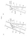
FIG. 4 (a) is a view of the instrument panel shown inFIG. 3 , taken along A-A and in the arrowed direction; -
FIG. 4 (b) is a view of the instrument panel shown inFIG. 3 , taken along B-B and in the arrowed direction; -
FIG. 5 is an enlarged view of a marginal portion formed on the rear surface side of the instrument panel in the embodiment and a lid supported by the marginal portion; -
FIG. 6 (a) is a cross- sectional view showing the cross-section on the right side of a marginal portion of an instrument panel in a second embodiment; and -
FIG. 6 (b) is a cross- sectional view showing the cross-section of the central portion of the marginal portion of the instrument panel in the second embodiment. - An instrument panel structure for a vehicle in a first embodiment according to the present invention will be described below, referring to the drawings. The same symbols will be assigned to the same elements.
The instrument panel structure for a vehicle in the present embodiment includes three members, namely, aninstrument panel 10 as a main body, alid 20 fitted on theinstrument panel 10, and anauxiliary panel 40. - The
instrument panel 10 is a panel for supporting various meters, switches, audios, and the like, and is fitted to the vehicle body of avehicle 1 such that various supported meters, switches, and the like face the inner side of avehicle interior 2, as shown inFIG. 1 (a) . Further, as shown inFIG. 1 (a) , theinstrument panel 10 is provided with anopening portion 11 on the left-lower side, and alid 20 for closing theopening portion 11 is fitted.
Theopening portion 11 is a hole for replacement task on a fuse, not shown, fitted on the rear surface side of theinstrument panel 10. As shown inFIGS. 1 and2 , theopening portion 11 is provided on thelower surface 10a of theinstrument panel 10. As shown inFIGS. 1(b) and 2 , thelower surface 10a is inclined such as to be closer to the vehicle front side as going downward. Accordingly, accompanying thelower surface 10a, theopening portion 11 is also an inclined hole such that the lower side is closer to the vehicle front side than the upper side. Further, theopening portion 11 is formed in a size that enables replacement of a fuse. The rear surface side of theinstrument panel 10 refers to the vehicle body side where theinstrument panel 10 is fitted, and the front surface side of theinstrument panel 10 refers to the side facing thevehicle interior 2.
Furthermore, theinstrument panel 10 is, as shown inFIG. 3 , provided on the rear surface side with amarginal portion 30 for removably supporting thelid 20, and is provided on the rear surface side of theinstrument panel 10 with anauxiliary panel 40.
Thelid 20, themarginal portion 30, and theauxiliary panel 40 will be described below in detail. - The
lid 20 is a lid member that is removably supported by themarginal portion 30 of theinstrument panel 10, and closes the openingportion 11. Thelid 20 has, as shown inFIG. 2 , a closingportion 21 for closing the openingportion 11,engagement portions 22 formed on the rear surface of the closingportion 21, and aprojection portion 23 projecting from the upper side of the closingportion 21. - The closing
portion 21 is, as shown inFIG. 2 , in a plate shape corresponding to the size of the openingportion 11 that is closed, and is formed such as to be on the same plane as the front surface side of theinstrument panel 10.
Further, as shown inFIG. 2 , theengagement portions 22 are used for engagement, being engaged into the engagement holes 33 of the later-described marginal portion 3, in order that the closingportion 21 holds the openingportion 11 in a closed state. Theengagement portions 22 are formed on the rear surface side of the closingportion 21 at positions corresponding to the engagement holes 33 of themarginal portion 30. - The
projection portion 23 is a portion that is supported by themarginal portion 30 formed on the rear surface of theinstrument panel 10, and projects upward from the rear surface side of the closingportion 21. Concretely, theprojection portion 23 is, as shown inFIG. 2 , includes a contact-engagedportion 24 projecting along the lateral direction of the closingportion 21 andconnection portions 25 for connecting the contact-engagedportion 24 and the closingportion 21. - The
connection portions 25 extend from the rear surface upper portion of the closingportion 21 to the rear surface side and further extend from there, and are formed substantially in an L-shape in a side view (refer toFIG. 4 (a) and Fig. 4 (b) ). Further, as shown inFIG. 2 , when thelid 20 is viewed from the front side, theconnection portions 25 include, a rightside connection portion 25a disposed on the right side and a leftside connection portion 25b disposed on the left side. - As shown in
FIG. 2 , when viewed from the front surface side of the closingportion 21, the contact-engagedportion 24 includes a right side contact-engagedportion 24a projecting from the right side surface of the rightside connection portion 25a, a left side contact-engagedportion 24b projecting from the left side surface of the leftside connection portion 25b, and a central contact-engagedportion 24c extending between the rightside connection portion 25a and the leftside connection portion 25b, along the lateral direction of the closingportion 21.
Further, as shown inFIG. 2 , the length L1 from the end portion of the right side contact-engagedportion 24a to the end portion of the left side contact-engagedportion 24b is formed to be longer than the distance L2 between a rightside support portion 31a and a leftside support portion 31b of asupport portion 31 of themarginal portion 30 described later. The distance between the rightside support portion 31a and the leftside support portion 31b of thesupport portion 31 and the distance between a rightside extension portion 32a and a leftside extension portion 32b of anextension portion 32 are formed to be the same, which will be described later. Further, 'L2' shown inFIG. 2 represents the distance between the rightside extension portion 32a of theextension portion 32 and the leftside extension portion 32b. - The right side contact-engaged
portion 24a and the left side contact-engagedportion 24b are formed in a shape with which the right side contact-engagedportion 24a and the left side contact-engagedportion 24b can be stopped by engagement in contact with aprotrusion portion 34 of themarginal portion 30, described later, and can slide on and move over theprotrusion portion 34 in contact when thelid 20 is moved downward. The right side contact-engagedportion 24a and the left side contact-engagedportion 24b are formed in, for example, in a shape of a cylinder, a chamfered triangular prism, or the like.
Further, the right side contact-engagedportion 24a and the left side contact-engagedportion 24b are formed such as to have a thickness that is a little larger than the gap L3 (refer toFIG. 4 ) formed by the later-describedprotrusion portion 34 of themarginal portion 30 and theauxiliary panel 40. - As shown in
FIG. 3 andFIG. 4(b) , the central contact-engagedportion 24c is engaged in contact with acentral support portion 31c of thesupport portion 31 described later, and is formed longer than thecentral support portion 31 with respect to the lateral direction. As neither the central contact-engagedportion 24c or the correspondingcentral support portion 31c is not an element that contributes to the structure, according to the present invention, of preventing drop-off of thelid 20, the shape and the like thereof is not particularly limited, however, with this arrangement, thelid 20 can be supported in a more stable state when thelid 20 is opened. - The
marginal portion 30 is, as shown inFIG. 3 , an element that removably supports thelid 20 for closing the openingportion 11, and is formed, on the rear surface side of theinstrument panel 10, in the margin of the upper end side and in the margins of the left/right sides of the openingportion 11.
Themarginal portion 30 is, as shown inFIG. 3 andFIG. 4(a) , includes thesupport portion 31 for supporting the contact-engagedportion 24 of thelid 20, theextension portion 32 extending from thesupport portion 31 to the rear surface lower side, the engagement holes 33 penetrating theextension portion 32, and theprotrusion portion 34 protruding from theextension portion 32 toward the rear surface upper side. - The
support portion 31 is a component for supporting the contact-engagedportion 24 formed at theprojection portion 23 of thelid 20. As shown inFIG. 3 , corresponding to the right side contact-engagedportion 24a, the left side contact-engagedportion 24b, and the central contact-engagedportion 24c of the contact-engagedportion 24 of thelid 20, thesupport portion 31 includes the rightside support portion 31a disposed on the right side, the leftside support portion 31b disposed on the left side, and thecentral support portion 31c disposed at the center.
The rightside support portion 31a is, as shown inFIG. 4 (a) , extending from the upper end side of the openingportion 11 of theinstrument panel 10 toward the vehicle front side and downward. The inclination angle of the rightside support portion 31a is, as shown inFIG. 4 (a) , formed to an extent at which the right side contact-engagedportion 24a engaged in contact with the rightside support portion 31a can slide to the rightside extension portion 32a side by the own-weight of thelid 20. The contact-engagedportion 24 of thelid 20 can thereby be engaged in contact with thesupport portion 31, and slides toward the rightside extension portion 32a side by the own-weight of thelid 20.
Further, similarly to the rightside support portion 31a, the leftside support portion 31b is also extending from the upper end side of the openingportion 11 of theinstrument panel 10 toward the vehicle front side, with an angular inclination.
The width L2, which is the distance between the rightside support portion 31a and the leftside support portion 31b, is formed smaller than the length L1 between the end portion of the right side contact-engagedportion 24a and the end portion of the left side contact-engagedportion 24b.
Thus, the right side contact-engagedportion 24a and the left side contact-engagedportion 24b on the both end sides of the contact-engagedportion 24 can be engaged in contact respectively with the rightside support portion 31a and the leftside support portion 31b, wherein the both end sides of thelid 20 are supported by thesupport portion 31.
Thecentral support portion 31c is, as shown inFIG. 4 (b) , extending from the upper end side of the openingportion 11 toward the rear surface side to an extent that thecentral support portion 31c can support the central contact-engagedportion 24c of the contact-engagedportion 24. Further, thecentral support portion 31c is formed, as shown inFIG. 3 , shorter than the width of the central contact-engagedportion 24c.
Still further, thesupport portion 31 is provided with respective notches between the rightside support portion 31a, thecentral support portion 31 c, and the leftside support portion 31b, wherein theconnection portion 25 of theprojection portion 23 of thelid 20 can pass the notches. Theconnection portion 25 of theprojection portion 23 of thelid 20 can pass the notches between the rightside support portion 31a, thecentral support portion 31c, and the leftside support portion 31b so that the contact-engagedportion 24 on the upper side of theprojection portion 23 can be disposed upper than thesupport portion 31. - The
extension portion 32 is a portion for preventing drop-off of thelid 20 from theinstrument panel 10 even in a case that the contact-engagedportion 24 of thelid 20 deviates from thesupport portion 31 to the rear surface side to lose support.
Theextension portion 32, as shown inFIGS. 2 and3 , includes the rightside extension portion 32a (refer toFIG. 4 (a) ) extending from the rear surface side end portion of the rightside support portion 31a of thesupport portion 31 toward the rear surface lower side, and the leftside extension portion 32b extending from the rear surface end portion of the leftside support portion 31b toward the rear surface lower side.
The distance between the rightside extension portion 32a and the leftside extension portion 32b is formed to be the same length as the distance L2 between the rightside support portion 31a and the leftside support portion 31b of thesupport portion 31.
Thus, even when thelid 20 has moved downward in parallel, the right side contact-engagedportion 24a and the left side contact-engagedportion 24b of thelid 20 are engaged in contact with theextension portion 32, and thelid 20 thereby is prevented from dropping-off from theinstrument panel 10.
By rotating thelid 20 in a state that the right side contact-engagedportion 24a and the left side contact-engagedportion 24b are engaged in contact with the rightside extension portion 32a and the leftside extension portion 32b, the right side contact-engagedportion 24a and the left side contact-engagedportion 24b stop the engagement so that thelid 20 can be removed from theinstrument panel 10. - The engagement holes 33 are, as shown in
FIG. 2 andFig. 4(a) , holes that theextension portion 32 penetrates, and are formed in a shape that enables engagement stop of theengagement portions 22 of thelid 20 by engaging of theengagement portions 22 into the engagement holes 33. Further, the engagement holes 33 are formed at positions that correspond to theengagement portions 22 formed on the rear surface side of thelid 20 when the openingportion 11 of thelid 20 is closed. - The
protrusion portion 34 includes, as shown inFIG. 3 , a rightside protrusion portion 34a formed by protrusion of the upper surface side of the rightside extension portion 32a in the vicinity of the rightside support portion 31 a, and a leftside protrusion portion 34b formed by protrusion of the upper surface side of the leftside extension portion 32b in the vicinity of the leftside support portion 31b.
Herein, the rightside protrusion portion 34a is, as shown inFIG. 4 (a) , formed in the vicinity of the rightside support portion 31a. Accordingly, as shown inFIG. 4 (a) , the contact-engagedportion 24a sliding along the rightside support portion 31a, which is an inclined surface, to the rightside extension portion 32a side comes in contact with the upper surface side of the rightside protrusion portion 34a and stops by engagement.
Further, the rightside protrusion portion 34a is, as shown inFIG. 4 (a) , formed in a shape with which the right side contact-engagedportion 24a can slide along and move over the rightside protrusion portion 34a in contact when thelid 20 is moved downward. The rightside protrusion portion 34a in the present embodiment is, as shown inFIG. 5 , protruding in a chamfered rectangular shape, however without being limited thereto, may be, for example, a protrusion in a half cylindrical shape.
Further, though bot shown, similarly to the rightside protrusion portion 34a, the leftside protrusion portion 34b is formed in the vicinity of the leftside support portion 31b, and is also formed in a shape with which the left side contact-engagedportion 24b can slide along and move over the leftside protrusion portion 34b when thelid 20 is moved downward.
Still further, the side surfaces on the lower sides of the rightside protrusion portion 34a and the leftside protrusion portion 34b are formed to be gradually inclined surfaces with respect to the surface of theextension portion 32. - An
auxiliary panel 40 will be described below. Theauxiliary panel 40 is, as shown inFIG. 3 , provided with afitting hole 41 and can be fitted to the rear surface side of theinstrument panel 10 by inserting thefitting member 13 formed on the rear surface side of theinstrument panel 10 into thefitting hole 41.
Theauxiliary panel 40 is formed, as shown inFIG. 4 (a) , such that a gap L3 between theauxiliary panel 40 and theprotrusion portion 34 of themarginal portion 30 is a little smaller than the thickness of the contact-engagedportion 24 of thelid 20. - With the above-described instrument panel structure for a vehicle in the present embodiment, by drawing the lower side of the
lid 20 for closing the openingportion 11 of theinstrument panel 10 toward the front surface side, the openingportion 11 can be made into an open state.
Further, thesupport portion 31 of themarginal portion 30, the contact-engagedportion 24 of thelid 20 being engaged in contact with thesupport portion 31, is formed such as to have inclination with which the contact-engagedportion 24 can slide to theextension portion 32a side by the own weight of thelid 20. Thereby, the contact-engagedportion 24 slides along thesupport portion 31 to theextension portion 32 side, and stops by engagement with theprotrusion portion 34. Accordingly, as shown inFIG. 4 (a) , when thelid 20 is open, the contact-engagedportion 24 of thelid 20 comes in contact with theprotrusion portion 34 and stops by engagement. - In case of removing the
lid 20 from theinstrument panel 10, thelid 20 is drawn downward. Herein, theprotrusion portion 34 where the contact-engagedportion 24 stops by engagement is formed in a shape with which the contact-engagedportion 24 in contact can slide along and move over theprotrusion portion 34 when thelid 20 is drawn downward. Accordingly, the contact-engagedportion 24 of thelid 20 moves to theextension portion 32 side, moving over theprotrusion portion 34, as shown inFIG. 5 by arrow C direction.
Further, as the distance L3 between theprotrusion portion 34 and theauxiliary panel 40 is, as shown inFIG. 4 (a) , set smaller than the thickness of the contact-engagedportion 24, when the contact-engagedportion 24 moves over theprotrusion portion 34, the contact-engagedportion 24 moves to theextension portion 32 side, while sliding on the two surfaces of theprotrusion portion 34 and theauxiliary panel 40.
Then, by rotating thelid 20, the contact-engagedportion 24 stops being engaged in contact with theextension portion 32, and thelid 20 can be removed from theinstrument panel 10. - Further, in order to fit the
lid 20, the contact-engagedportion 24 of thelid 20 is made engaged in contact withextension portion 32 of themarginal portion 30, and is drawn upward. In this occasion, as the side surfaces of the lower sides of the rightside protrusion portion 34a and the leftside protrusion portion 34b, which are in contact with the rightside protrusion portion 34a and the leftside protrusion portion 34b, are inclined, the contact-engagedportion 24 of thelid 20 can slide without stopping by engagement, move over theprotrusion portion 34, and get engaged in contact with thesupport portion 31. - It may occur that a passenger kicks by mistake the
lid 20 in a state that the openingportion 11 is closed, or a worker unintentionally contacts thelid 20 in a state that the openingportion 11 is open and thelid 20 is supported by thesupport portion 31 such as to be stopped by engagement with theprotrusion portion 34 of themarginal portion 30.
Even in such a case, according to theinstrument panel 10 in the present embodiment, as the contact-engagedportion 24 of thelid 20 is engaged in contact with theprotrusion portion 34 formed on theextension portion 32, the contact-engagedportion 24 does not linearly move toward theextension portion 32 side.
Further, even when the contact-engagedportion 24 of thelid 20 moves along and over the surface of theprotrusion portion 34 and moves to theextension portion 32 side, as the gap L3 between theprotrusion portion 34 and theauxiliary panel 40 is formed to be a little smaller than the thickness of the contact-engagedportion 24 of thelid 20, the contact-engagedportion 24 of thelid 20 is sandwiched by the gap between theprotrusion portion 34 and theauxiliary panel 40.
Further, likewise, even when thelid 20 is moved upper than theprotrusion portion 34 by the above-described contact, as the gap L3 between theprotrusion portion 34 and theauxiliary panel 40 is formed a little smaller than the thickness of the contact-engagedportion 24 of thelid 20, as shown inFIG. 4 (a) , the contact-engagedportion 24 of thelid 20 does not move over theprotrusion portion 34 without contacting theprotrusion portion 34.
Therefore, with theinstrument panel 10 in the present embodiment, as it does not occur that the contact-engagedportion 24 of thelid 20 moves to theextension portion 32 side by contact or the like and that thelid 20 rotates, thelid 20 does not easily drop off.
Further, regarding removing thelid 20, thelid 20 can be easily removed by simple operations of opening the lower portion of thelid 20 and drawing downward and rotating thelid 20. - Still further, with the instrument panel structure for a vehicle in the present embodiment, it is only necessary to form the margins of the opening
portion 11 of theinstrument panel 10 and thelid 20 in the above-described shapes, there is no problem that additional members are necessary and the cost increases. - The instrument panel structure for a vehicle in the foregoing embodiment has been described above, however, the invention is not limited to the instrument panel structure for a vehicle in the foregoing embodiment.
For example, theprotrusion portion 34 of themarginal portion 30 in the foregoing embodiment has both the rightside protrusion portion 34a and the leftside protrusion portion 34b, however, only either one may be employed. This is because, even when theprotrusion portion 34 includes only the rightside protrusion portion 34a formed on the rightside extension portion 32a, the contact-engagedportion 24 of thelid 20 can come in contact with the rightside protrusion portion 34a and be stopped by engagement. - An instrument panel structure for a vehicle in a second embodiment according to the present invention will be described below, referring to the drawings.
The instrument panel structure for a vehicle in the second embodiment includes aninstrument panel 10b, alid 20, and anauxiliary panel 40, and is different from the instrument panel structure for a vehicle in the first embodiment in that the instrument panel structure for a vehicle in the second embodiment includes theinstrument panel 10b.
More concretely, the difference between theinstrument panel 10b in the second embodiment and theinstrument panel 10 in the first embodiment is that amarginal portion 30a, of theinstrument panel 10b, disposed on the rear surface side includes asupport portion 131 in the second embodiment, while themarginal portion 30 of theinstrument panel 10 includes thesupport portion 31 in the first embodiment.
In the following, the instrument panel structure for a vehicle in the second embodiment will be described only on thesupport portion 131, which is the difference from the first embodiment, and description of the same elements as those in the first embodiment will be omitted. - The
support portion 131 of themarginal portion 30a includes a rightside support portion 131a, a left side support portion 131b, and acentral support portion 131c, corresponding to a right side contact-engagedportion 24a, a left side contact-engagedportion 24b, and a central contact-engagedportion 24c of a contact-engagedportion 24 of thelid 20.
The rightside support portion 131a, as shown inFIG. 6 , extends from the upper end side of anopening portion 11 of theinstrument panel 10b toward the vehicle front side, while inclining downward.
Further, the inclination angle of the rightside support portion 131a is, as shown inFIG. 6 (a) , an angle with which the right side contact-engagedportion 24a can be supported, and also an angle that enables directing the right side contact-engagedportion 24a to theextension portion 32 side when thelid 20 is moved downward in a state that the right side contact-engagedportion 24a is supported. Further, a left side support portion, not shown, and thecentral support portion 131, shown inFIG. 6 (b) , are also formed similarly to the rightside support portion 131a. - With the above-described instrument panel structure for a vehicle in the second embodiment, when the lower side of the
lid 20 for closing the openingportion 11 of theinstrument panel 10b is drawn to the front surface side, the contact-engagedportion 24 of thelid 20 gets supported in a state of engagement in contact with thesupport portion 131 of themarginal portion 30a of theinstrument panel 10.
Further, when thelid 20 is moved down toward the lower side in order to remove thelid 20, the contact-engagedportion 24 of thelid 20 slides to the rightside extension portion 32 side, along thesupport portion 131 inclined to theextension portion 32 side, and comes in contact with theprotrusion portion 34 to stop by engagement.
Then, when thelid 20 is further moved downward, the contact-engagedportion 24 slides on and move over theprotrusion portion 34 to theextension portion 32 side.
Further, as shown inFIG. 6 (a) , as the distance L3 between theprotrusion portion 34 and theauxiliary panel 40 is set smaller than the thickness of the contact-engagedportion 24, when the contact-engagedportion 24 moves over theprotrusion portion 34, the contact-engagedportion 24 moves to theextension portion 32 side while sliding on the two surfaces of theprotrusion portion 34 and theauxiliary panel 40.
As has been described above, according to the second embodiment, even when a passenger unintentionally kicks thelid 20, and the contact-engagedportion 24 of thelid 20, as shown inFIG. 6 , linearly moves toward theextension portion 32 side, the contact-engagedportion 24 does not move to theextension portion 32 side because theprotrusion portion 34 is formed and the contact-engagedportion 24 comes in contact with theprotrusion portion 34 and stops by engagement.
Further, even when the contact-engagedportion 24 of thelid 20 moves along and over the surface of theprotrusion portion 34 to theextension portion 32 side, the contact-engagedportion 24 is sandwiched by the gap between theprotrusion portion 34 and theauxiliary panel 40 as the gap L3 between theprotrusion portion 34 and theauxiliary panel 40 is set a little smaller than the thickness of the contact-engagedportion 24 of thelid 20.
In such a manner, also with theinstrument panel 10b in the second embodiment, it does not occur that the contact-engagedportion 24 of thelid 20 moves to theextension portion 32 side and thelid 20 rotates, and thelid 20 accordingly does not easily drop off. Thus, it is possible to provide an instrument panel structure, for a vehicle, where a lid hardly drops-off. -
- 1..
- vehicle
- 2..
- vehicle interior
- 10, 10b..
- instrument panel
- 11..
- opening portion
- 20..
- lid
- 21..
- closing portion
- 22..
- engagement portion
- 23..
- projection portion
- 24, 24a-24c..
- contact-engaged portion
- 25, 25a, 25b..
- connection portion
- 30, 30a..
- marginal portion
- 31, 31a-31c, 131, 131a, 131c..
- support portion
- 32, 32a, 32b..
- extension portion
- 33..
- engagement hole
- 34, 34a, 34b..
- protrusion portion
- 40..
- auxiliary panel
- 41..
- fitting hole
Claims (6)
- A vehicle instrument panel structure having an opening portion for maintenance of components disposed inside an instrument panel for a vehicle and a lid covering the opening portion, the vehicle instrument panel structure comprising:a projection portion projecting from an upper portion of the lid to a rear surface side of a margin of the opening portion; anda protrusion portion at which the projection portion of the lid stops by engagement in a state that a lower portion of the lid is open, the protrusion portion being formed on the rear surface side of the margin of the opening portion of the instrument panel,wherein the protrusion portion is formed in such a manner that, when the lid is moved downward in the state that the lower portion of the lid is open, the projection portion can move over the protrusion portion that stops the projection portion by engagement, and the lid can be thereby removed from the instrument panel.
- A vehicle instrument panel structure having an opening portion for maintenance of components disposed inside an instrument panel for a vehicle and a lid covering the opening portion, the vehicle instrument panel structure comprising:a projection portion projecting from an upper portion of the lid to a rear surface side of a margin of the opening portion; anda protrusion portion at which the projection portion of the lid stops by engagement when the lid is moved downward in a state that a lower portion of the lid is open, the protrusion portion being formed on the rear surface side of the margin of the opening portion of the instrument panel,wherein the protrusion portion is formed such that, when the lid is moved downward in the state that the lower portion of the lid is open, the projection portion can move over the protrusion portion that stops the projection portion by engagement, and the lid can be thereby removed from the instrument panel.
- The vehicle instrument panel structure according to claim 1 or 2,
wherein the projecting portion of the lid is provided with a contact-engaged portion that stops at the protrusion portion by engagement,
and wherein the rear surface side of the margin of the opening portion of the instrument panel is provided with:a support portion for supporting the contact-engaged portion when the lid is open;an extension portion continuously extending downward from the support portion; andthe protrusion portion that is protruding from a part of the extension portion. - The vehicle instrument panel structure according to claim 3, wherein the protrusion portion is formed in a vicinity of the support portion.
- The vehicle instrument panel structure according to claim 3,
wherein an auxiliary panel for covering the margin of the opening portion is fitted on the instrument panel,
and wherein a gap between the protrusion portion and the auxiliary panel is set in a size that enables sandwiching the contact-engaged portion. - The vehicle instrument panel structure according to claim 4,
wherein an auxiliary panel for covering the margin of the opening portion is fitted on the instrument panel,
and wherein a gap between the protrusion portion and the auxiliary panel is set in a size that enables sandwiching the contact-engaged portion.
Applications Claiming Priority (2)
| Application Number | Priority Date | Filing Date | Title |
|---|---|---|---|
| JP2009239013 | 2009-10-16 | ||
| PCT/JP2010/067417 WO2011046040A1 (en) | 2009-10-16 | 2010-10-05 | Vehicle instrument panel structure |
Publications (3)
| Publication Number | Publication Date |
|---|---|
| EP2489540A1 true EP2489540A1 (en) | 2012-08-22 |
| EP2489540A4 EP2489540A4 (en) | 2013-07-10 |
| EP2489540B1 EP2489540B1 (en) | 2014-11-19 |
Family
ID=43876091
Family Applications (1)
| Application Number | Title | Priority Date | Filing Date |
|---|---|---|---|
| EP10823308.1A Not-in-force EP2489540B1 (en) | 2009-10-16 | 2010-10-05 | Vehicle instrument panel structure |
Country Status (5)
| Country | Link |
|---|---|
| US (1) | US8702144B2 (en) |
| EP (1) | EP2489540B1 (en) |
| JP (1) | JP5466708B2 (en) |
| CN (1) | CN102574468B (en) |
| WO (1) | WO2011046040A1 (en) |
Families Citing this family (8)
| Publication number | Priority date | Publication date | Assignee | Title |
|---|---|---|---|---|
| CN102574468B (en) * | 2009-10-16 | 2015-04-01 | 本田技研工业株式会社 | Vehicle instrument panel structure |
| US9157258B2 (en) * | 2013-10-08 | 2015-10-13 | Honda Motor Co., Ltd. | Vehicle interior lid for covering trunk lid unlocking mechanism |
| US10343611B2 (en) * | 2013-10-08 | 2019-07-09 | Honda Motor Co., Ltd. | Vehicle interior lid for covering interior component airbag attachment |
| JP2015098293A (en) | 2013-11-20 | 2015-05-28 | スズキ株式会社 | Mounting structure for instrument panel mounting parts |
| FR3021933B1 (en) * | 2014-06-10 | 2018-05-18 | Renault S.A.S | ARRANGEMENT OF A DASHBOARD FITTING ELEMENT OF A MOTOR VEHICLE ON A SUPPORT ELEMENT OF THIS DASHBOARD |
| MY191435A (en) * | 2015-07-23 | 2022-06-27 | Honda Motor Co Ltd | Instrument panel structure |
| US10076958B1 (en) * | 2017-06-28 | 2018-09-18 | Ford Global Technologies, Llc | Collapsible panel duct for a vehicle HVAC system |
| US10889226B1 (en) | 2019-10-14 | 2021-01-12 | Ford Global Technologies, Llc | Vehicle pedal cover |
Citations (1)
| Publication number | Priority date | Publication date | Assignee | Title |
|---|---|---|---|---|
| DE10039519A1 (en) | 2000-08-08 | 2002-02-21 | Chemex Gmbh | Feeder insert used for casting metals comprises mold elements which slide into each other along a longitudinal axis to surround a hollow space for liquid metal |
Family Cites Families (22)
| Publication number | Priority date | Publication date | Assignee | Title |
|---|---|---|---|---|
| JPS57209441A (en) * | 1981-06-17 | 1982-12-22 | Nissan Motor Co Ltd | Fuse box structure for automobile |
| JPS587355U (en) * | 1981-07-06 | 1983-01-18 | ソニー株式会社 | lead frame |
| JPS5873554A (en) * | 1981-10-26 | 1983-05-02 | 松下電器産業株式会社 | Case |
| JPS63101449U (en) | 1986-12-22 | 1988-07-01 | ||
| JPH0630534Y2 (en) * | 1987-10-15 | 1994-08-17 | 日産自動車株式会社 | Lid structure for closing plate openings |
| JPH0710943Y2 (en) * | 1988-07-19 | 1995-03-15 | ダイハツ工業株式会社 | Cover mounting structure on the side of the instrument panel |
| JP2500328Y2 (en) * | 1991-03-28 | 1996-06-05 | 日本プラスト株式会社 | Fuse box lid mounting device |
| DE4204495C2 (en) | 1992-02-14 | 1994-07-21 | Daimler Benz Ag | Dashboard bracket fixed to the vehicle body |
| JPH08233108A (en) * | 1994-12-26 | 1996-09-10 | Casio Comput Co Ltd | Shield structure for container opening |
| JPH09175228A (en) * | 1995-12-25 | 1997-07-08 | Nishikawa Kasei Co Ltd | Side structure of resin instrument panel and engagement structure of lid member to main body |
| JPH11291793A (en) * | 1998-04-10 | 1999-10-26 | Nishikawa Kasei Co Ltd | Mounting structure for resin molded products for automobiles |
| JP3596311B2 (en) * | 1998-10-19 | 2004-12-02 | 日産自動車株式会社 | Opening / closing lid mounting structure |
| JP2002293192A (en) * | 2001-03-30 | 2002-10-09 | Piolax Inc | Supporting structure of slice lid |
| JP2003323872A (en) * | 2002-04-30 | 2003-11-14 | Matsushita Electric Ind Co Ltd | Accommodation equipment |
| JP4011441B2 (en) * | 2002-05-10 | 2007-11-21 | ダイハツ工業株式会社 | Instrument panel structure of vehicle |
| JP3839378B2 (en) * | 2002-08-29 | 2006-11-01 | 本田技研工業株式会社 | Vibration welding structure for instrument panel mounting members |
| JP2004131211A (en) * | 2002-10-09 | 2004-04-30 | Ricoh Co Ltd | Drawer device, feeding device provided with the drawer device, and image forming apparatus |
| US7036865B2 (en) * | 2004-04-08 | 2006-05-02 | Honda Motor Co., Ltd. | Automobile instrument panel structure |
| JP2006138076A (en) * | 2004-11-10 | 2006-06-01 | Yamaha Livingtec Corp | Vestibule door, door base material for vestibule door, and door auxiliary material for vestibule door |
| JP4632139B2 (en) * | 2007-02-06 | 2011-02-16 | スズキ株式会社 | Garnish mounting structure on the instrument panel |
| JP4541390B2 (en) * | 2007-10-16 | 2010-09-08 | 本田技研工業株式会社 | Lid mounting structure |
| CN102574468B (en) * | 2009-10-16 | 2015-04-01 | 本田技研工业株式会社 | Vehicle instrument panel structure |
-
2010
- 2010-10-05 CN CN201080046822.3A patent/CN102574468B/en not_active Expired - Fee Related
- 2010-10-05 WO PCT/JP2010/067417 patent/WO2011046040A1/en not_active Ceased
- 2010-10-05 US US13/501,886 patent/US8702144B2/en not_active Expired - Fee Related
- 2010-10-05 EP EP10823308.1A patent/EP2489540B1/en not_active Not-in-force
- 2010-10-05 JP JP2011536102A patent/JP5466708B2/en not_active Expired - Fee Related
Patent Citations (1)
| Publication number | Priority date | Publication date | Assignee | Title |
|---|---|---|---|---|
| DE10039519A1 (en) | 2000-08-08 | 2002-02-21 | Chemex Gmbh | Feeder insert used for casting metals comprises mold elements which slide into each other along a longitudinal axis to surround a hollow space for liquid metal |
Also Published As
| Publication number | Publication date |
|---|---|
| WO2011046040A1 (en) | 2011-04-21 |
| US8702144B2 (en) | 2014-04-22 |
| EP2489540A4 (en) | 2013-07-10 |
| EP2489540B1 (en) | 2014-11-19 |
| CN102574468A (en) | 2012-07-11 |
| CN102574468B (en) | 2015-04-01 |
| US20120200108A1 (en) | 2012-08-09 |
| JP5466708B2 (en) | 2014-04-09 |
| JPWO2011046040A1 (en) | 2013-03-07 |
Similar Documents
| Publication | Publication Date | Title |
|---|---|---|
| EP2489540A1 (en) | Vehicle instrument panel structure | |
| EP2075160B1 (en) | Console box structure | |
| EP2412657B1 (en) | Elevator control panel | |
| US9902372B2 (en) | Wiper arm | |
| US10220748B2 (en) | Vehicular interior part | |
| JP6732535B2 (en) | container | |
| JP2015157666A (en) | Control board for elevator | |
| JP4110206B1 (en) | Board case and board mounting apparatus | |
| JP5271885B2 (en) | Folding container with divider | |
| CN106660489A (en) | Console assembly | |
| JP2009240341A (en) | Game machine | |
| JP4909957B2 (en) | Game machine | |
| CN108602471B (en) | Interior structure for vehicle | |
| JP5410394B2 (en) | Transport container | |
| JP3013566U (en) | Card box | |
| JP4629074B2 (en) | Game machine | |
| JP5451553B2 (en) | Combustion equipment | |
| JP4641543B2 (en) | Game machine | |
| JP2008150913A (en) | Door lock mechanism of box | |
| JP2010143262A (en) | Storage device for vehicle | |
| JP4983758B2 (en) | Internal unit attachment / detachment mechanism | |
| KR100526963B1 (en) | Assembly structure for mat of tray for vehicles | |
| CN205469315U (en) | A construction package for motor vehicles | |
| JP2008049774A (en) | Resin arm structure | |
| JP2005119356A (en) | Glove box structure |
Legal Events
| Date | Code | Title | Description |
|---|---|---|---|
| PUAI | Public reference made under article 153(3) epc to a published international application that has entered the european phase |
Free format text: ORIGINAL CODE: 0009012 |
|
| 17P | Request for examination filed |
Effective date: 20120424 |
|
| AK | Designated contracting states |
Kind code of ref document: A1 Designated state(s): AL AT BE BG CH CY CZ DE DK EE ES FI FR GB GR HR HU IE IS IT LI LT LU LV MC MK MT NL NO PL PT RO RS SE SI SK SM TR |
|
| DAX | Request for extension of the european patent (deleted) | ||
| TPAC | Observations filed by third parties |
Free format text: ORIGINAL CODE: EPIDOSNTIPA |
|
| A4 | Supplementary search report drawn up and despatched |
Effective date: 20130606 |
|
| RIC1 | Information provided on ipc code assigned before grant |
Ipc: B60K 37/00 20060101AFI20130531BHEP |
|
| 17Q | First examination report despatched |
Effective date: 20140115 |
|
| GRAP | Despatch of communication of intention to grant a patent |
Free format text: ORIGINAL CODE: EPIDOSNIGR1 |
|
| INTG | Intention to grant announced |
Effective date: 20140708 |
|
| GRAS | Grant fee paid |
Free format text: ORIGINAL CODE: EPIDOSNIGR3 |
|
| GRAA | (expected) grant |
Free format text: ORIGINAL CODE: 0009210 |
|
| AK | Designated contracting states |
Kind code of ref document: B1 Designated state(s): AL AT BE BG CH CY CZ DE DK EE ES FI FR GB GR HR HU IE IS IT LI LT LU LV MC MK MT NL NO PL PT RO RS SE SI SK SM TR |
|
| REG | Reference to a national code |
Ref country code: GB Ref legal event code: FG4D |
|
| REG | Reference to a national code |
Ref country code: CH Ref legal event code: EP |
|
| REG | Reference to a national code |
Ref country code: AT Ref legal event code: REF Ref document number: 696784 Country of ref document: AT Kind code of ref document: T Effective date: 20141215 |
|
| REG | Reference to a national code |
Ref country code: IE Ref legal event code: FG4D |
|
| REG | Reference to a national code |
Ref country code: DE Ref legal event code: R096 Ref document number: 602010020450 Country of ref document: DE Effective date: 20141231 |
|
| REG | Reference to a national code |
Ref country code: NL Ref legal event code: VDEP Effective date: 20141119 |
|
| REG | Reference to a national code |
Ref country code: AT Ref legal event code: MK05 Ref document number: 696784 Country of ref document: AT Kind code of ref document: T Effective date: 20141119 |
|
| REG | Reference to a national code |
Ref country code: LT Ref legal event code: MG4D |
|
| PG25 | Lapsed in a contracting state [announced via postgrant information from national office to epo] |
Ref country code: LT Free format text: LAPSE BECAUSE OF FAILURE TO SUBMIT A TRANSLATION OF THE DESCRIPTION OR TO PAY THE FEE WITHIN THE PRESCRIBED TIME-LIMIT Effective date: 20141119 Ref country code: IS Free format text: LAPSE BECAUSE OF FAILURE TO SUBMIT A TRANSLATION OF THE DESCRIPTION OR TO PAY THE FEE WITHIN THE PRESCRIBED TIME-LIMIT Effective date: 20150319 Ref country code: NL Free format text: LAPSE BECAUSE OF FAILURE TO SUBMIT A TRANSLATION OF THE DESCRIPTION OR TO PAY THE FEE WITHIN THE PRESCRIBED TIME-LIMIT Effective date: 20141119 Ref country code: ES Free format text: LAPSE BECAUSE OF FAILURE TO SUBMIT A TRANSLATION OF THE DESCRIPTION OR TO PAY THE FEE WITHIN THE PRESCRIBED TIME-LIMIT Effective date: 20141119 Ref country code: FI Free format text: LAPSE BECAUSE OF FAILURE TO SUBMIT A TRANSLATION OF THE DESCRIPTION OR TO PAY THE FEE WITHIN THE PRESCRIBED TIME-LIMIT Effective date: 20141119 Ref country code: PT Free format text: LAPSE BECAUSE OF FAILURE TO SUBMIT A TRANSLATION OF THE DESCRIPTION OR TO PAY THE FEE WITHIN THE PRESCRIBED TIME-LIMIT Effective date: 20150319 Ref country code: NO Free format text: LAPSE BECAUSE OF FAILURE TO SUBMIT A TRANSLATION OF THE DESCRIPTION OR TO PAY THE FEE WITHIN THE PRESCRIBED TIME-LIMIT Effective date: 20150219 |
|
| PG25 | Lapsed in a contracting state [announced via postgrant information from national office to epo] |
Ref country code: HR Free format text: LAPSE BECAUSE OF FAILURE TO SUBMIT A TRANSLATION OF THE DESCRIPTION OR TO PAY THE FEE WITHIN THE PRESCRIBED TIME-LIMIT Effective date: 20141119 Ref country code: GR Free format text: LAPSE BECAUSE OF FAILURE TO SUBMIT A TRANSLATION OF THE DESCRIPTION OR TO PAY THE FEE WITHIN THE PRESCRIBED TIME-LIMIT Effective date: 20150220 Ref country code: AT Free format text: LAPSE BECAUSE OF FAILURE TO SUBMIT A TRANSLATION OF THE DESCRIPTION OR TO PAY THE FEE WITHIN THE PRESCRIBED TIME-LIMIT Effective date: 20141119 Ref country code: SE Free format text: LAPSE BECAUSE OF FAILURE TO SUBMIT A TRANSLATION OF THE DESCRIPTION OR TO PAY THE FEE WITHIN THE PRESCRIBED TIME-LIMIT Effective date: 20141119 Ref country code: CY Free format text: LAPSE BECAUSE OF FAILURE TO SUBMIT A TRANSLATION OF THE DESCRIPTION OR TO PAY THE FEE WITHIN THE PRESCRIBED TIME-LIMIT Effective date: 20141119 Ref country code: PL Free format text: LAPSE BECAUSE OF FAILURE TO SUBMIT A TRANSLATION OF THE DESCRIPTION OR TO PAY THE FEE WITHIN THE PRESCRIBED TIME-LIMIT Effective date: 20141119 Ref country code: LV Free format text: LAPSE BECAUSE OF FAILURE TO SUBMIT A TRANSLATION OF THE DESCRIPTION OR TO PAY THE FEE WITHIN THE PRESCRIBED TIME-LIMIT Effective date: 20141119 Ref country code: RS Free format text: LAPSE BECAUSE OF FAILURE TO SUBMIT A TRANSLATION OF THE DESCRIPTION OR TO PAY THE FEE WITHIN THE PRESCRIBED TIME-LIMIT Effective date: 20141119 |
|
| PG25 | Lapsed in a contracting state [announced via postgrant information from national office to epo] |
Ref country code: EE Free format text: LAPSE BECAUSE OF FAILURE TO SUBMIT A TRANSLATION OF THE DESCRIPTION OR TO PAY THE FEE WITHIN THE PRESCRIBED TIME-LIMIT Effective date: 20141119 Ref country code: RO Free format text: LAPSE BECAUSE OF FAILURE TO SUBMIT A TRANSLATION OF THE DESCRIPTION OR TO PAY THE FEE WITHIN THE PRESCRIBED TIME-LIMIT Effective date: 20141119 Ref country code: DK Free format text: LAPSE BECAUSE OF FAILURE TO SUBMIT A TRANSLATION OF THE DESCRIPTION OR TO PAY THE FEE WITHIN THE PRESCRIBED TIME-LIMIT Effective date: 20141119 Ref country code: CZ Free format text: LAPSE BECAUSE OF FAILURE TO SUBMIT A TRANSLATION OF THE DESCRIPTION OR TO PAY THE FEE WITHIN THE PRESCRIBED TIME-LIMIT Effective date: 20141119 Ref country code: SK Free format text: LAPSE BECAUSE OF FAILURE TO SUBMIT A TRANSLATION OF THE DESCRIPTION OR TO PAY THE FEE WITHIN THE PRESCRIBED TIME-LIMIT Effective date: 20141119 |
|
| REG | Reference to a national code |
Ref country code: DE Ref legal event code: R097 Ref document number: 602010020450 Country of ref document: DE |
|
| PLBE | No opposition filed within time limit |
Free format text: ORIGINAL CODE: 0009261 |
|
| STAA | Information on the status of an ep patent application or granted ep patent |
Free format text: STATUS: NO OPPOSITION FILED WITHIN TIME LIMIT |
|
| REG | Reference to a national code |
Ref country code: FR Ref legal event code: PLFP Year of fee payment: 6 |
|
| 26N | No opposition filed |
Effective date: 20150820 |
|
| PG25 | Lapsed in a contracting state [announced via postgrant information from national office to epo] |
Ref country code: IT Free format text: LAPSE BECAUSE OF FAILURE TO SUBMIT A TRANSLATION OF THE DESCRIPTION OR TO PAY THE FEE WITHIN THE PRESCRIBED TIME-LIMIT Effective date: 20141119 |
|
| PGFP | Annual fee paid to national office [announced via postgrant information from national office to epo] |
Ref country code: DE Payment date: 20150930 Year of fee payment: 6 Ref country code: GB Payment date: 20151021 Year of fee payment: 6 |
|
| PG25 | Lapsed in a contracting state [announced via postgrant information from national office to epo] |
Ref country code: SI Free format text: LAPSE BECAUSE OF FAILURE TO SUBMIT A TRANSLATION OF THE DESCRIPTION OR TO PAY THE FEE WITHIN THE PRESCRIBED TIME-LIMIT Effective date: 20141119 |
|
| PGFP | Annual fee paid to national office [announced via postgrant information from national office to epo] |
Ref country code: FR Payment date: 20151023 Year of fee payment: 6 |
|
| PG25 | Lapsed in a contracting state [announced via postgrant information from national office to epo] |
Ref country code: LU Free format text: LAPSE BECAUSE OF FAILURE TO SUBMIT A TRANSLATION OF THE DESCRIPTION OR TO PAY THE FEE WITHIN THE PRESCRIBED TIME-LIMIT Effective date: 20151005 |
|
| REG | Reference to a national code |
Ref country code: CH Ref legal event code: PL |
|
| PG25 | Lapsed in a contracting state [announced via postgrant information from national office to epo] |
Ref country code: MC Free format text: LAPSE BECAUSE OF FAILURE TO SUBMIT A TRANSLATION OF THE DESCRIPTION OR TO PAY THE FEE WITHIN THE PRESCRIBED TIME-LIMIT Effective date: 20141119 |
|
| REG | Reference to a national code |
Ref country code: IE Ref legal event code: MM4A |
|
| PG25 | Lapsed in a contracting state [announced via postgrant information from national office to epo] |
Ref country code: CH Free format text: LAPSE BECAUSE OF NON-PAYMENT OF DUE FEES Effective date: 20151031 Ref country code: LI Free format text: LAPSE BECAUSE OF NON-PAYMENT OF DUE FEES Effective date: 20151031 |
|
| PG25 | Lapsed in a contracting state [announced via postgrant information from national office to epo] |
Ref country code: IE Free format text: LAPSE BECAUSE OF NON-PAYMENT OF DUE FEES Effective date: 20151005 |
|
| REG | Reference to a national code |
Ref country code: DE Ref legal event code: R119 Ref document number: 602010020450 Country of ref document: DE |
|
| PG25 | Lapsed in a contracting state [announced via postgrant information from national office to epo] |
Ref country code: BG Free format text: LAPSE BECAUSE OF FAILURE TO SUBMIT A TRANSLATION OF THE DESCRIPTION OR TO PAY THE FEE WITHIN THE PRESCRIBED TIME-LIMIT Effective date: 20141119 Ref country code: HU Free format text: LAPSE BECAUSE OF FAILURE TO SUBMIT A TRANSLATION OF THE DESCRIPTION OR TO PAY THE FEE WITHIN THE PRESCRIBED TIME-LIMIT; INVALID AB INITIO Effective date: 20101005 Ref country code: SM Free format text: LAPSE BECAUSE OF FAILURE TO SUBMIT A TRANSLATION OF THE DESCRIPTION OR TO PAY THE FEE WITHIN THE PRESCRIBED TIME-LIMIT Effective date: 20141119 |
|
| GBPC | Gb: european patent ceased through non-payment of renewal fee |
Effective date: 20161005 |
|
| REG | Reference to a national code |
Ref country code: FR Ref legal event code: ST Effective date: 20170630 |
|
| PG25 | Lapsed in a contracting state [announced via postgrant information from national office to epo] |
Ref country code: GB Free format text: LAPSE BECAUSE OF NON-PAYMENT OF DUE FEES Effective date: 20161005 Ref country code: FR Free format text: LAPSE BECAUSE OF NON-PAYMENT OF DUE FEES Effective date: 20161102 Ref country code: DE Free format text: LAPSE BECAUSE OF NON-PAYMENT OF DUE FEES Effective date: 20170503 |
|
| PG25 | Lapsed in a contracting state [announced via postgrant information from national office to epo] |
Ref country code: TR Free format text: LAPSE BECAUSE OF FAILURE TO SUBMIT A TRANSLATION OF THE DESCRIPTION OR TO PAY THE FEE WITHIN THE PRESCRIBED TIME-LIMIT Effective date: 20141119 Ref country code: MT Free format text: LAPSE BECAUSE OF FAILURE TO SUBMIT A TRANSLATION OF THE DESCRIPTION OR TO PAY THE FEE WITHIN THE PRESCRIBED TIME-LIMIT Effective date: 20141119 |
|
| PG25 | Lapsed in a contracting state [announced via postgrant information from national office to epo] |
Ref country code: BE Free format text: LAPSE BECAUSE OF FAILURE TO SUBMIT A TRANSLATION OF THE DESCRIPTION OR TO PAY THE FEE WITHIN THE PRESCRIBED TIME-LIMIT Effective date: 20141119 |
|
| PG25 | Lapsed in a contracting state [announced via postgrant information from national office to epo] |
Ref country code: MK Free format text: LAPSE BECAUSE OF FAILURE TO SUBMIT A TRANSLATION OF THE DESCRIPTION OR TO PAY THE FEE WITHIN THE PRESCRIBED TIME-LIMIT Effective date: 20141119 |
|
| PG25 | Lapsed in a contracting state [announced via postgrant information from national office to epo] |
Ref country code: AL Free format text: LAPSE BECAUSE OF FAILURE TO SUBMIT A TRANSLATION OF THE DESCRIPTION OR TO PAY THE FEE WITHIN THE PRESCRIBED TIME-LIMIT Effective date: 20141119 |