EP2489539A1 - Auto inter-axle differential lock engagement for improved braking capacity - Google Patents
Auto inter-axle differential lock engagement for improved braking capacity Download PDFInfo
- Publication number
- EP2489539A1 EP2489539A1 EP12154464A EP12154464A EP2489539A1 EP 2489539 A1 EP2489539 A1 EP 2489539A1 EP 12154464 A EP12154464 A EP 12154464A EP 12154464 A EP12154464 A EP 12154464A EP 2489539 A1 EP2489539 A1 EP 2489539A1
- Authority
- EP
- European Patent Office
- Prior art keywords
- vehicle
- wheel assembly
- controller
- coupled
- brake
- Prior art date
- Legal status (The legal status is an assumption and is not a legal conclusion. Google has not performed a legal analysis and makes no representation as to the accuracy of the status listed.)
- Granted
Links
Images


Classifications
-
- B—PERFORMING OPERATIONS; TRANSPORTING
- B60—VEHICLES IN GENERAL
- B60T—VEHICLE BRAKE CONTROL SYSTEMS OR PARTS THEREOF; BRAKE CONTROL SYSTEMS OR PARTS THEREOF, IN GENERAL; ARRANGEMENT OF BRAKING ELEMENTS ON VEHICLES IN GENERAL; PORTABLE DEVICES FOR PREVENTING UNWANTED MOVEMENT OF VEHICLES; VEHICLE MODIFICATIONS TO FACILITATE COOLING OF BRAKES
- B60T8/00—Arrangements for adjusting wheel-braking force to meet varying vehicular or ground-surface conditions, e.g. limiting or varying distribution of braking force
- B60T8/24—Arrangements for adjusting wheel-braking force to meet varying vehicular or ground-surface conditions, e.g. limiting or varying distribution of braking force responsive to vehicle inclination or change of direction, e.g. negotiating bends
- B60T8/245—Longitudinal vehicle inclination
-
- B—PERFORMING OPERATIONS; TRANSPORTING
- B60—VEHICLES IN GENERAL
- B60K—ARRANGEMENT OR MOUNTING OF PROPULSION UNITS OR OF TRANSMISSIONS IN VEHICLES; ARRANGEMENT OR MOUNTING OF PLURAL DIVERSE PRIME-MOVERS IN VEHICLES; AUXILIARY DRIVES FOR VEHICLES; INSTRUMENTATION OR DASHBOARDS FOR VEHICLES; ARRANGEMENTS IN CONNECTION WITH COOLING, AIR INTAKE, GAS EXHAUST OR FUEL SUPPLY OF PROPULSION UNITS IN VEHICLES
- B60K23/00—Arrangement or mounting of control devices for vehicle transmissions, or parts thereof, not otherwise provided for
- B60K23/08—Arrangement or mounting of control devices for vehicle transmissions, or parts thereof, not otherwise provided for for changing number of driven wheels, for switching from driving one axle to driving two or more axles
- B60K23/0808—Arrangement or mounting of control devices for vehicle transmissions, or parts thereof, not otherwise provided for for changing number of driven wheels, for switching from driving one axle to driving two or more axles for varying torque distribution between driven axles, e.g. by transfer clutch
-
- B—PERFORMING OPERATIONS; TRANSPORTING
- B60—VEHICLES IN GENERAL
- B60K—ARRANGEMENT OR MOUNTING OF PROPULSION UNITS OR OF TRANSMISSIONS IN VEHICLES; ARRANGEMENT OR MOUNTING OF PLURAL DIVERSE PRIME-MOVERS IN VEHICLES; AUXILIARY DRIVES FOR VEHICLES; INSTRUMENTATION OR DASHBOARDS FOR VEHICLES; ARRANGEMENTS IN CONNECTION WITH COOLING, AIR INTAKE, GAS EXHAUST OR FUEL SUPPLY OF PROPULSION UNITS IN VEHICLES
- B60K28/00—Safety devices for propulsion-unit control, specially adapted for, or arranged in, vehicles, e.g. preventing fuel supply or ignition in the event of potentially dangerous conditions
- B60K28/10—Safety devices for propulsion-unit control, specially adapted for, or arranged in, vehicles, e.g. preventing fuel supply or ignition in the event of potentially dangerous conditions responsive to conditions relating to the vehicle
- B60K28/16—Safety devices for propulsion-unit control, specially adapted for, or arranged in, vehicles, e.g. preventing fuel supply or ignition in the event of potentially dangerous conditions responsive to conditions relating to the vehicle responsive to, or preventing, spinning or skidding of wheels
- B60K28/165—Safety devices for propulsion-unit control, specially adapted for, or arranged in, vehicles, e.g. preventing fuel supply or ignition in the event of potentially dangerous conditions responsive to conditions relating to the vehicle responsive to, or preventing, spinning or skidding of wheels acting on elements of the vehicle drive train other than the propulsion unit and brakes, e.g. transmission, clutch, differential
-
- B—PERFORMING OPERATIONS; TRANSPORTING
- B60—VEHICLES IN GENERAL
- B60W—CONJOINT CONTROL OF VEHICLE SUB-UNITS OF DIFFERENT TYPE OR DIFFERENT FUNCTION; CONTROL SYSTEMS SPECIALLY ADAPTED FOR HYBRID VEHICLES; ROAD VEHICLE DRIVE CONTROL SYSTEMS FOR PURPOSES NOT RELATED TO THE CONTROL OF A PARTICULAR SUB-UNIT
- B60W10/00—Conjoint control of vehicle sub-units of different type or different function
- B60W10/12—Conjoint control of vehicle sub-units of different type or different function including control of differentials
- B60W10/14—Central differentials for dividing torque between front and rear axles
-
- B—PERFORMING OPERATIONS; TRANSPORTING
- B60—VEHICLES IN GENERAL
- B60W—CONJOINT CONTROL OF VEHICLE SUB-UNITS OF DIFFERENT TYPE OR DIFFERENT FUNCTION; CONTROL SYSTEMS SPECIALLY ADAPTED FOR HYBRID VEHICLES; ROAD VEHICLE DRIVE CONTROL SYSTEMS FOR PURPOSES NOT RELATED TO THE CONTROL OF A PARTICULAR SUB-UNIT
- B60W10/00—Conjoint control of vehicle sub-units of different type or different function
- B60W10/18—Conjoint control of vehicle sub-units of different type or different function including control of braking systems
- B60W10/184—Conjoint control of vehicle sub-units of different type or different function including control of braking systems with wheel brakes
-
- B—PERFORMING OPERATIONS; TRANSPORTING
- B60—VEHICLES IN GENERAL
- B60W—CONJOINT CONTROL OF VEHICLE SUB-UNITS OF DIFFERENT TYPE OR DIFFERENT FUNCTION; CONTROL SYSTEMS SPECIALLY ADAPTED FOR HYBRID VEHICLES; ROAD VEHICLE DRIVE CONTROL SYSTEMS FOR PURPOSES NOT RELATED TO THE CONTROL OF A PARTICULAR SUB-UNIT
- B60W30/00—Purposes of road vehicle drive control systems not related to the control of a particular sub-unit, e.g. of systems using conjoint control of vehicle sub-units
- B60W30/18—Propelling the vehicle
- B60W30/18009—Propelling the vehicle related to particular drive situations
- B60W30/18109—Braking
-
- B—PERFORMING OPERATIONS; TRANSPORTING
- B60—VEHICLES IN GENERAL
- B60W—CONJOINT CONTROL OF VEHICLE SUB-UNITS OF DIFFERENT TYPE OR DIFFERENT FUNCTION; CONTROL SYSTEMS SPECIALLY ADAPTED FOR HYBRID VEHICLES; ROAD VEHICLE DRIVE CONTROL SYSTEMS FOR PURPOSES NOT RELATED TO THE CONTROL OF A PARTICULAR SUB-UNIT
- B60W2300/00—Indexing codes relating to the type of vehicle
- B60W2300/50—Tilting frame vehicles
-
- B—PERFORMING OPERATIONS; TRANSPORTING
- B60—VEHICLES IN GENERAL
- B60W—CONJOINT CONTROL OF VEHICLE SUB-UNITS OF DIFFERENT TYPE OR DIFFERENT FUNCTION; CONTROL SYSTEMS SPECIALLY ADAPTED FOR HYBRID VEHICLES; ROAD VEHICLE DRIVE CONTROL SYSTEMS FOR PURPOSES NOT RELATED TO THE CONTROL OF A PARTICULAR SUB-UNIT
- B60W2520/00—Input parameters relating to overall vehicle dynamics
- B60W2520/06—Direction of travel
-
- B—PERFORMING OPERATIONS; TRANSPORTING
- B60—VEHICLES IN GENERAL
- B60W—CONJOINT CONTROL OF VEHICLE SUB-UNITS OF DIFFERENT TYPE OR DIFFERENT FUNCTION; CONTROL SYSTEMS SPECIALLY ADAPTED FOR HYBRID VEHICLES; ROAD VEHICLE DRIVE CONTROL SYSTEMS FOR PURPOSES NOT RELATED TO THE CONTROL OF A PARTICULAR SUB-UNIT
- B60W2552/00—Input parameters relating to infrastructure
- B60W2552/15—Road slope, i.e. the inclination of a road segment in the longitudinal direction
Definitions
- the present disclosure relates to a braking system for a vehicle, and more particularly to an automatic inter-axle differential lock for increasing the braking capacity of a work vehicle.
- articulated dump trucks typically include a cab portion having a first frame supporting an operator cab, and a trailer portion having a second frame supporting a bin.
- the bin may be configured to contain a load and is typically coupled to an actuator for angular movement relative to the second frame.
- the first frame and the second frame may be operably coupled through an articulation joint.
- a front wheel assembly coupled to the first frame may provide rolling support to the cab portion, and a rear wheel assembly coupled to the second frame may provide rolling support to the trailer portion.
- the vehicle When a work vehicle, such as an ADT, is inclined on a slope with the front wheel assembly positioned higher than the rear wheel assembly, the vehicle may experience a weight transfer towards the rear of the vehicle. Accordingly, the front axle braking force applied to the ground may be limited due to reduced traction of the front wheels.
- a work vehicle including a chassis and a front wheel assembly supporting the chassis.
- the front wheel assembly includes a front axle and a pair of wheels coupled to the front axle.
- a front brake is coupled to the front wheel assembly and configured to apply a braking force to the front wheel assembly to inhibit rotation of the front axle.
- a rear wheel assembly supports the chassis and includes at least one rear axle and a pair of wheels coupled to the rear axle.
- a drive shaft is coupled between the front wheel assembly and the rear wheel assembly.
- a differential is coupled to the drive shaft and includes a lock configured to substantially block operation of the differential.
- a direction sensor is configured to detect a moving direction of the vehicle.
- a controller in communication with the differential and the direction sensor is configured to engage the lock device upon detection of the vehicle moving in a reverse direction.
- a work vehicle including a chassis and a front wheel assembly operably coupled to the chassis to support the chassis.
- the front wheel assembly includes a front axle and a pair of wheels coupled to the front axle.
- a rear wheel assembly is operably coupled to the chassis to support the chassis.
- the rear wheel assembly includes at least one rear axle and a pair of wheels coupled to the rear axle.
- a drive shaft is coupled between the front wheel assembly and the rear wheel assembly.
- a differential coupled to the drive shaft includes a lock device configured to substantially lock the differential.
- a first sensor is configured to detect a slope of the ground, and a second sensor is configured to detect a speed of the vehicle.
- a controller in communication with the differential and the first and second sensors is configured to engage the lock device upon detection of the vehicle being at least one of stopped on a slope and moving down a slope.
- a work vehicle including a chassis and a front wheel assembly coupled to the chassis to support the chassis.
- the front wheel assembly includes a front axle and a pair of wheels coupled to the front axle.
- a rear wheel assembly coupled to the chassis to support the chassis includes at least one rear axle and a pair of wheels coupled to the rear axle.
- a front brake is coupled to the front wheel assembly and is configured to apply a braking torque to the front wheel assembly to inhibit rotation of the front axle.
- the work vehicle includes a detection means for detecting an operating condition of the vehicle.
- the work vehicle further includes a transfer means for transferring a braking torque from the front wheel assembly to the rear wheel assembly.
- the work vehicle further includes a means for activating the transfer means upon detection of the operating condition by the detection means.
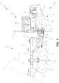
- an exemplary articulated vehicle 10 includes a chassis 11 having a first or cab portion 12 and a second or trailer portion 16.
- Cab portion 12 includes a first frame 14, and trailer portion 16 includes a second frame 18.
- First frame 14 is connected to second frame 18 through a coupling assembly 20.
- coupling assembly 20 includes a pivot frame coupling 22 and a rotational frame coupling 26.
- Pivot frame coupling 22 provides for articulated movement, or pivoting, of second frame 18 relative to first frame 14 about a vertical axis 24.
- Rotational frame coupling 26 provides for rotational movement of second frame 18 relative to first frame 14 about a longitudinal axis 28.
- vehicle 10 includes one or more hydraulic actuators configured to control the angle between first and second frames 14, 18 for steering vehicle 10.
- First frame 14 illustratively supports an operator's cab 30 and an engine 31 for propelling vehicle 10.
- a first or front wheel assembly 32 supports cab portion 12 and is operably coupled to first frame 14.
- First wheel assembly 32 includes a pair of wheels 34 for providing rolling support to cab portion 12.
- a dump body or bin 35 for containing a load is supported by second frame 18.
- An actuator such as a hydraulic cylinder 37, may be coupled to bin 35 for angularly elevating bin 35 relative to second frame 18 (as shown in phantom in FIG. 1 ).
- a second or rear wheel assembly 33 is operably coupled to second frame 18 for supporting trailer portion 16.
- rear wheel assembly 33 includes front wheels 40 and rear wheels 42.
- rear wheel assembly 33 illustratively includes a left rear wheel assembly 36a and a right rear wheel assembly 36b.
- Left and right rear wheel assemblies 36a, 36b each illustratively include a front wheel 40a, 40b and a rear wheel 42a, 42b, respectively.
- each of front wheels 40a, 40b and rear wheels 42a, 42b are rotatably coupled to a tandem or walking beam 44 (see also FIG. 6 ).
- tandem 44 is pivotally coupled to second frame 18 through a pivot tandem coupling 46.
- tandem 44 facilitates pivoting movement of front wheel 40 relative to rear wheel 42 about coupling 46, thereby facilitating continuous ground engagement by wheels 40 and 42.
- coupling 46 consists of a rigid shaft that extends from second frame 18 to tandem 44 to provide the pivoting therebetween.
- shaft 46 illustratively has a fixed position relative to second frame 18 such that shaft 46 moves vertically, longitudinally, and laterally with second frame 18.
- front and rear wheels 40 and 42 are at a fixed distance from shaft 46.
- the vertical location of the axis of rotation of front and rear wheels 40 and 42 relative to second frame 18 is independent of the load carried by bin 35.
- the spring constant between second frame 18 and tandem 44 is large so that there is substantially no body roll between second frame 18 and tandem 44.
- Vehicle 10 may include alternative wheel assembly configurations. For example, fewer or more wheels and/or axles may support trailer portion 16 and/or cab portion 12.
- FIG. 2 an exemplary drive train 48 of vehicle 10 is illustrated.
- Engine 31 is coupled to a drive shaft 56 via a transmission 51 for driving front and rear wheel assemblies 32, 33.
- transmission 51 is an automatic transmission, although other types of transmissions may be provided.
- Front wheel assembly 32 includes a front axle assembly 50
- rear wheel assembly 33 includes a bogie or rear axle assembly 52.
- Front axle assembly 50 includes a front axle 54 coupled between wheels 34a, 34b and a differential 62 coupled to front axle 54.
- Bogie axle assembly 52 includes a first rear axle 58 coupled between wheels 40a, 40b and a second rear axle 60 coupled between wheels 42a, 42b.
- first rear axle 58 includes a first differential 66 and second rear axle 60 includes a second differential 68. Tandems 44 of left and right rear wheel assemblies 36a, 36b are further included in bogie axle assembly 52 and coupled to first and second rear axles 58, 60.
- Drive shaft 56 is coupled to front axle 54 of front axle assembly 50 and to first and second rear axles 58, 60 of bogie axle assembly 52.
- Drive shaft 56 is configured to provide torque from transmission 51 and engine 31 to front axle 54 and first and second rear axles 58, 60 for propelling vehicle 10.
- differential 62 of front axle 54 is coupled to drive shaft 56 and is configured to provide torque from drive shaft 56 to each wheel 34a, 34b while allowing wheels 34a, 34b to rotate at different speeds.
- differentials 66, 68 of respective rear axles 58, 60 are coupled to drive shaft 56 and are configured to provide torque from drive shaft 56 to respective wheels 40, 42 while allowing individual wheels 40, 42 to rotate at different speeds.
- drive shaft 56 includes an inter-axle differential 64 configured to allow rear axles 58, 60 to rotate at different speeds than front axle 54 during operation of vehicle 10.
- drive shaft 56 includes a first portion 70 coupled between front axle assembly 50 and differential 64 and a second portion 72 coupled between differential 64 and bogie axle assembly 52.
- Front axle 54 is coupled to first portion 70
- first and second rear axles 58, 60 are coupled to second portion 72.
- Differential 64 serves to allow first portion 70 and second portion 72 of drive shaft 56 to rotate at different speeds during operation of vehicle 10, thereby allowing front axle 54 to rotate at different speeds than first and second rear axles 58, 60.
- transmission 51 is coupled to differential 64 for driving drive shaft 56.
- transmission 51 and differential 64 are provided in a single assembly, and an output shaft 98 of transmission 51 forms a part of second portion 72 of drive shaft 56.
- Alternative configurations of coupling transmission 51 to drive shaft 56 may be provided.
- Differential 64 includes a lock 94 (see FIG. 3 ) for selectively disengaging or locking differential 64.
- lock 94 includes a clutch assembly.
- first portion 70 of drive shaft 56 is locked to second portion 72 to rotate therewith.
- lock 94 is disengaged or opened, differential 64 is in an unlocked and operational state and is configured to allow first portion 70 and second portion 72 to rotate at different speeds.
- front axle 54 of front wheel assembly 32 may rotate at a different speed than first and second rear axles 58, 60 of rear wheel assembly 33 when lock 94 is disengaged.
- a controller such as exemplary controller 82 of FIG. 3 , controls operation of inter-axle differential 64 and differential lock 94.
- Differentials 62, 66, 68 may also include locks or clutches.
- Lock 94 may be configured to completely lock differential 64 or to partially lock differential 64.
- lock 94 may limit rotation of front portion 70 of drive shaft 56 relative to second portion 72 of drive shaft 56 without completely locking front portion 70 to second portion 72.
- lock 94 may comprise a clutch assembly that blocks rotation of front portion 70 relative to second portion 72 based on the frictional holding capacity of the clutch assembly.
- Braking system 80 includes front brakes 102 coupled to front axle 54 of front axle assembly 50 and rear brakes 104 coupled to at least one of rear axles 58, 60 of bogie axle assembly 52.
- two front brakes 102a, 102b are coupled to front axle 54 for applying a braking force to front axle 54
- a rear brake 104 is coupled to first rear axle 58 for applying a braking force to both rear axles 58, 60, as illustrated in FIG. 2 .
- rear brake 104 coupled to first rear axle 58 may apply braking torque to second rear axle 60 through drive shaft 56.
- Front axle 54 and rear axles 58, 60 may have other brake configurations.
- brakes 102, 104 are hydraulically-actuated disc brakes, although brakes 102, 104 may be other suitable types.
- controller 82 of braking system 80 is configured to control brakes 102, 104 and differential 64. Controller 82 is configured to control brakes 102, 104 based on input from a brake input device 100.
- brake input device 100 includes a pedal or lever, but may include other suitable input devices for applying a brake.
- Controller 82 controls inter-axle differential 64 and differential lock 94 based on various vehicle parameters and user inputs, as described herein. Controller 82 may also control the operation of differentials 62, 66, 68 illustrated in FIG. 2 .
- Controller 82 may be a vehicle control unit of vehicle 10, but may alternatively be a separate controller from the vehicle control unit.
- controller 82 includes a processor 110 having memory 112 containing software configured to analyze inputs from various vehicle sensors for controlling differential 64.
- a user interface 85 may be provided for the operator to access controller 82, for example, to modify settings or to enter instructions.
- User interface 85 may be of conventional design, such as a keypad or control panel, and may be positioned within cab 30.
- User interface 85 may include a display for providing an operator with vehicle information, such as vehicle speed, diagnostics, differential feedback, sensor information, or other vehicle parameters.
- vehicle 10 when vehicle 10 is positioned on an incline or slope with front wheel assembly 32 positioned higher than rear wheel assembly 33, vehicle 10 may experience a weight transfer towards rear wheels 40, 42.
- the weight distribution of vehicle 10 shifts towards the rear of vehicle 10 when vehicle 10 is positioned on a slope with the back of trailer portion 16 facing down the slope.
- This weight transfer may cause reduced traction of front wheels 34a, 34b, thereby limiting the braking force of front axle 54 and front wheels 34a, 34b applied to the ground.
- the application of front brake 102 to front axle 54 results in a front axle braking force applied to the ground with wheels 34a, 34b.
- This front axle braking force may be reduced when vehicle 10 is inclined up a slope due to reduced traction of wheels 34a, 34b.
- braking system 80 is configured to provide additional braking capacity to vehicle 10 in certain operating conditions.
- braking system 80 is configured to transfer braking torque from front axle assembly 50 to bogie axle assembly 52 when vehicle 10 is reversing down a slope and when vehicle 10 is substantially stopped at an incline on a slope, as described herein.
- controller 82 is configured to automatically engage differential lock 94 of differential 64 based on various control inputs to transfer braking torque from front axle assembly 50 to bogie axle assembly 52. By locking differential 64, first and second portions 70, 72 of drive shaft 56 are locked to rotate together. As such, braking force applied to front axle 54 is configured to transfer to rear axles 58, 60 via drive shaft 56.
- lock 94 comprises a clutch assembly.
- the amount of braking torque transferred from front axle assembly 50 to bogie axle assembly 52 with lock 94 engaged may be limited to the frictional holding capacity of the clutch of lock 94.
- the maximum front axle braking torque transferred by drive shaft 56 to bogie axle assembly 52 may limited to the maximum frictional holding force capacity of the clutch plates of lock 94.
- controller 82 causes the automatic engagement of differential lock 94 based on inputs 96 from vehicle sensors 114.
- Inputs 96 may include the driving direction of vehicle 10, the speed of vehicle 10, the slope of the ground, the position of brake input device 100, the applied brake pressure, and/or the weight distribution of vehicle 10. Fewer or additional inputs 96 may be provided to controller 82 for controlling differential 64.
- sensors 114 include a speed sensor 83, a direction sensor 84, a slope sensor 86, a brake position sensor 88, and a brake pressure sensor 90 in communication with controller 82.
- sensors 114 further include one or more weight sensors 92 for detecting the weight distribution of vehicle 10.
- Speed sensor 83 is configured to measure the speed of vehicle 10 and provide a signal to controller 82 representative of the measured speed. Speed sensor 83 may measure the wheel speed, transmission speed, and/or engine speed of vehicle 10.
- Direction sensor 84 detects forward or reverse movement of vehicle 10 and provides a signal to controller 82 indicative of the detected moving direction of vehicle 10.
- direction sensor 84 and speed sensor 83 are provided with a single sensor.
- speed sensor 83 includes a variable reluctance or Hall effect sensor, but any suitable sensor 83 for detecting speed and/or direction may be used.
- Slope sensor 86 is configured to measure the slope of the ground under vehicle 10 (i.e., the inclination angle of vehicle 10) and provide a signal representative of the measured ground slope to controller 82.
- Slope sensor 86 may comprise a conventional inclinometer or another suitable slope angle sensor.
- Brake position sensor 88 is configured to provide a signal to controller 82 representative of the position of brake input device 100.
- brake position sensor 88 may include a conventional potentiometer coupled to a foot pedal or lever of brake input device 100 to measure the travel distance of brake input device 100.
- Other suitable brake position sensors 88 may also be used.
- Brake pressure sensor 90 is configured to measure the brake pressure applied by front brakes 102 and/or rear brakes 104 and to provide a signal or signals representative of the measured brake pressures to controller 82.
- brake system 80 may further include one or more weight sensors 92 for measuring the weight supported by front wheel assembly 32 and/or rear wheel assembly 33.
- a weight sensor 92 is coupled to each of left and right rear wheel assemblies 36a, 36b for independently measuring the weight supported by each rear wheel assembly 36a, 36b and providing signals indicative of the measured loads to controller 82.
- Trailer portion 16 and any load contained therein may contribute to the measured weight at rear wheel assembly 33.
- the weight of cab portion 12 may also contribute to the weight on wheel assemblies 36a, 36b.
- each weight sensor 92 includes a strain gauge mounted to a structure of rear wheel assembly 33, such as walking beam 44, for example, for detecting the weight of vehicle 10. See, for example, weight sensor 92 mounted to walking beam 44 illustrated in FIG. 6 .
- strain gauge or weight sensor 92 is positioned in a cavity 65 located in a top surface 45 of walking beam 44.
- sensor 92 and cavity 65 are positioned near a center portion of walking beam 44 and above shaft 46 for detecting the load on beam 44, although sensor 92 may be positioned in other suitable positions.
- a cover 67 is provided in cavity 65 to substantially enclose sensor 92 within cavity 65.
- a seal is provided between cover 67 and the surface forming cavity 65 to provide a sealed enclosure for sensor 92.
- a sensor cable 69 is configured to couple sensor 92 to controller 82 for providing feedback to controller 82.
- weight sensors 92 may include other suitable types and may be mounted at other locations suitable for measuring the weight supported by rear wheel assembly 33.
- one or more weight sensors 92 are coupled to front wheel assembly 32 for measuring weight supported by front wheel assembly 32. In one embodiment, based on the input from weight sensors 92, controller 82 may compare the measured weights on rear wheel assemblies 36a, 36b and front wheel assembly 32 to determine the weight distribution of vehicle 10.
- controller 82 determines the moving direction of vehicle 10 with direction sensor 84. If vehicle 10 is not moving in reverse, controller 82 determines at block 160 whether vehicle 10 is stopped based on feedback from speed sensor 83. In one embodiment, vehicle 10 is considered stopped if the detected vehicle speed is substantially zero. Alternatively, vehicle 10 may be considered stopped at block 160 if vehicle 10 is moving at a minimal forward speed, for example, less than 3 miles per hour.
- controller 82 determines at block 152 if vehicle 10 is positioned on an incline (i.e., if front wheel assembly 32 is positioned vertically above rear wheel assembly 33). If vehicle 10 is positioned on an incline, controller 82 determines at block 154 if the inclination angle of vehicle 10 exceeds a minimum threshold angle. In one embodiment, the minimum threshold angle is three degrees. In one embodiment, the minimum threshold angle is five degrees. In one embodiment, the minimum threshold angle is ten degrees. Other suitable minimum threshold angles may be used.
- controller 82 may determine at block 156 if other conditions are met. For example, controller 82 may check the position of brake input device 100 with brake position sensor 88 to determine if the operator has engaged the brakes. If brake input device 100 is engaged or if brake input device 100 has moved a predetermined distance, controller 82 may proceed to block 158 to engage differential lock 94. In one embodiment, controller 82 may further check the brake pressure of front brakes 102 and/or rear brakes 104 at block 156 and proceed to block 158 if the brake pressure exceeds a predetermined minimum brake pressure. In one embodiment, controller 82 may proceed directly to block 158 after determining at block 154 that vehicle 10 is positioned on a slope having an angle of inclination greater than the minimum threshold angle.
- controller 82 engages lock 94 to lock differential 64, thereby locking first portion 70 of drive shaft 56 to second portion 72 of drive shaft 56 (see FIG. 2 ). As such, at least a portion of the front axle braking torque applied with front brakes 102 transfers to bogie axle assembly 52 to provide increased braking capacity to vehicle 10.
- controller 82 disengages lock 94 upon at least one of the conditions of blocks 150, 152, 154, 156, and 160 no longer being satisfied.
- controller 82 may disengage lock 94 upon vehicle 10 moving forward or vehicle 10 no longer being positioned on a slope having the minimum threshold angle. Other conditions may also cause controller 82 to disengage lock 94.
- controller 82 may be configured to modulate or vary the holding capacity of lock 94 by adjusting the position of the clutch plates of lock 94. For example, controller 82 may allow the clutch of lock 94 to slip to reduce the frictional holding capacity of the lock 94. Controller 82 may vary the holding capacity of lock 94 based on various vehicle parameters.
- the weight supported by rear wheel assembly 33 and/or front wheel assembly 32 is calculated and considered by controller 82 in initiating the engagement of differential lock 94.
- the minimum inclination angle required to engage lock 94 may be reduced when a larger vehicle payload is detected with weight sensors 92.
- controller 82 may provide a stronger holding capacity with lock 94 when a larger payload is detected and a weaker holding capacity with lock 94 when a smaller payload is detected.
- FIGS. 5A and 5B each illustrate an exemplary brake holding force (measured in kilo-Newtons) of front and rear axles 54, 58, 60 based on the slope of the ground under vehicle 10.
- FIGS. 5A and 5B illustrate the braking torque transferred to the ground by front and rear brakes 102, 104.
- the ground slope is illustrated as a slope or grade percentage ranging from a 10% grade to a 60% grade. For example, at a 30% slope, the ground rises 30 units of vertical distance for every 100 units of horizontal distance.
- FIGS. 5A and 5B each illustrate an exemplary brake holding force (measured in kilo-Newtons) of front and rear axles 54, 58, 60 based on the slope of the ground under vehicle 10.
- FIGS. 5A and 5B illustrate the braking torque transferred to the ground by front and rear brakes 102, 104.
- the ground slope is illustrated as a slope or grade percentage ranging from a 10% grade to a 60% grade. For example, at a 30% slope
- vehicle 10 is positioned up the slope such that front wheel assembly 32 is positioned vertically above rear wheel assembly 33 (i.e., the back of trailer portion 16 faces down the slope).
- the tire traction coefficient of friction is 0.5.
- Curve 180 of FIGS. 5A and 5B illustrates the brake holding force required to hold vehicle 10 stationary on the slope.
- Curve 184 of FIGS. 5A and 5B illustrates the brake holding force provided with front axle 54 to the ground.
- curve 184 illustrates the brake holding force transferred to the ground through front axle 54 with the engagement of brakes 102.
- the potential brake holding force provided through front axle 54 is less than the required brake holding force for vehicle 10 for all slope levels.
- Curve 182 of FIG. 5A illustrates an exemplary actual brake holding force applied to the ground with front and rear axles 54, 58, 60 when differential lock 94 of differential 64 is in an unlocked or disengaged state.
- curve 182 illustrates the combined brake holding force transferred to the ground through front axle 54 with brakes 102 and through rear axles 58, 60 with brake 104.
- Curve 182' of FIG. 5B illustrates an exemplary actual brake holding force applied to the ground with front and rear axles 54, 58, 60 when differential lock 94 of differential 64 is in a locked or engaged state.
- curve 182' illustrates the combined brake holding force transferred to the ground when the braking force of front brakes 102 is transferred from front axle 54 to rear axles 58, 60 through drive shaft 56.
- the actual brake holding force 182 begins to deviate from the required braking force 180 at about a 30% slope and maxes out at about a 40% slope.
- the actual brake holding force 182' transferred to the ground provides the required holding force 180 for ground slopes ranging from about 10% slope to about 50% slope before beginning to deviate from the required holding force 180 at about a 50% slope.
- the engagement of differential lock 94 while vehicle 10 is positioned up a slope provides increased braking capacity to vehicle 10, particularly at slopes greater than 30%, as illustrated by curve 182' of FIG. 5B .
- lock 94 is automatically engaged when vehicle 10 is traveling down a slope.
- controller 82 may automatically engage lock 94 upon detection of vehicle 10 moving down a slope in either a forward or reverse direction.
- controller 82 may automatically engage lock 94 upon detection of vehicle 10 moving in a reverse direction.
- Braking system 80 may further include additional speed retarders 120 for slowing or braking vehicle 10, as illustrated in FIG. 3 .
- a transmission retarder 122 may be configured to slow the rotational speed of transmission 51 (see FIG. 2 ) under certain vehicle operating conditions.
- Transmission retarder 122 may include a hydrodynamic retarder and/or an electromagnetic retarder.
- An exhaust brake 124 and/or an engine braking system 126 may be further implemented in braking system 80 to facilitate speed reduction of vehicle 10.
- exhaust brake 124 may include a valve, such as a butterfly valve, mounted in the exhaust of vehicle 10 for restricting airflow and slowing engine 31.
- Engine brake 126 may include an engine valve brake configured to increase compression in engine 31 to slow engine 31.
- transmission retarder 122, exhaust brake 124, and/or the engine braking system 126 may be deactivated or ineffective when vehicle 10 is moving at a slow speed.
- braking system 80 is described herein with respect to articulated vehicle 10, braking system 80 may be implemented on other types of vehicles.
- braking system 80 may be implemented in other work or utility vehicles such as a motor grader, a tractor, a bulldozer, a feller buncher, a crawler, an excavator, a skidder, or another utility vehicle.
- braking system 80 may also be implemented in a commercial vehicle or other roadworthy motor vehicles.
Landscapes
- Engineering & Computer Science (AREA)
- Transportation (AREA)
- Mechanical Engineering (AREA)
- Chemical & Material Sciences (AREA)
- Combustion & Propulsion (AREA)
- Automation & Control Theory (AREA)
- Regulating Braking Force (AREA)
Abstract
Description
- The present disclosure relates to a braking system for a vehicle, and more particularly to an automatic inter-axle differential lock for increasing the braking capacity of a work vehicle.
- Work vehicles, such as articulated work vehicles, are known in the art. For example, articulated dump trucks (ADT's) typically include a cab portion having a first frame supporting an operator cab, and a trailer portion having a second frame supporting a bin. The bin may be configured to contain a load and is typically coupled to an actuator for angular movement relative to the second frame. The first frame and the second frame may be operably coupled through an articulation joint. A front wheel assembly coupled to the first frame may provide rolling support to the cab portion, and a rear wheel assembly coupled to the second frame may provide rolling support to the trailer portion.
- When a work vehicle, such as an ADT, is inclined on a slope with the front wheel assembly positioned higher than the rear wheel assembly, the vehicle may experience a weight transfer towards the rear of the vehicle. Accordingly, the front axle braking force applied to the ground may be limited due to reduced traction of the front wheels.
- According to an embodiment of the present disclosure, a work vehicle is provided including a chassis and a front wheel assembly supporting the chassis. The front wheel assembly includes a front axle and a pair of wheels coupled to the front axle. A front brake is coupled to the front wheel assembly and configured to apply a braking force to the front wheel assembly to inhibit rotation of the front axle. A rear wheel assembly supports the chassis and includes at least one rear axle and a pair of wheels coupled to the rear axle. A drive shaft is coupled between the front wheel assembly and the rear wheel assembly. A differential is coupled to the drive shaft and includes a lock configured to substantially block operation of the differential. A direction sensor is configured to detect a moving direction of the vehicle. A controller in communication with the differential and the direction sensor is configured to engage the lock device upon detection of the vehicle moving in a reverse direction.
- In another exemplary embodiment of the present disclosure, a work vehicle is provided including a chassis and a front wheel assembly operably coupled to the chassis to support the chassis. The front wheel assembly includes a front axle and a pair of wheels coupled to the front axle. A rear wheel assembly is operably coupled to the chassis to support the chassis. The rear wheel assembly includes at least one rear axle and a pair of wheels coupled to the rear axle. A drive shaft is coupled between the front wheel assembly and the rear wheel assembly. A differential coupled to the drive shaft includes a lock device configured to substantially lock the differential. A first sensor is configured to detect a slope of the ground, and a second sensor is configured to detect a speed of the vehicle. A controller in communication with the differential and the first and second sensors is configured to engage the lock device upon detection of the vehicle being at least one of stopped on a slope and moving down a slope.
- In yet another exemplary embodiment of the present disclosure, a work vehicle is provided including a chassis and a front wheel assembly coupled to the chassis to support the chassis. The front wheel assembly includes a front axle and a pair of wheels coupled to the front axle. A rear wheel assembly coupled to the chassis to support the chassis includes at least one rear axle and a pair of wheels coupled to the rear axle. A front brake is coupled to the front wheel assembly and is configured to apply a braking torque to the front wheel assembly to inhibit rotation of the front axle. The work vehicle includes a detection means for detecting an operating condition of the vehicle. The work vehicle further includes a transfer means for transferring a braking torque from the front wheel assembly to the rear wheel assembly. The work vehicle further includes a means for activating the transfer means upon detection of the operating condition by the detection means.
- The above-mentioned and other features and advantages of the invention, and the manner of attaining them, will become more apparent and the disclosure itself will be better understood by reference to the following description taken in conjunction with the accompanying drawings, wherein:
- FIG. 1
- illustrates an exemplary articulated vehicle incorporating the braking system of the present disclosure;
- FIG. 2
- illustrates a top schematic view of the articulated vehicle of
FIG. 1 with a front wheel assembly and a rear wheel assembly; - FIG. 3
- illustrates a representative view of an exemplary braking system of the vehicle of
FIG. 1 ; - FIG. 4
- illustrates an exemplary method of providing additional braking capacity to the vehicle of
FIG. 1 ; - FIG. 5A
- illustrates an exemplary braking holding force of the vehicle of
FIG. 1 with a disengaged inter-axle differential lock; - FIG. 5B
- illustrates an exemplary braking holding force of the vehicle of
FIG. 1 with an engaged inter-axle differential lock; and - FIG. 6
- illustrates an exemplary walking beam of the vehicle of
FIG. 1 including a weight sensor. - Corresponding reference characters indicate corresponding parts throughout the several views. The exemplifications set out herein illustrate exemplary embodiments of the invention, and such exemplifications are not to be construed as limiting the scope of the invention in any manner.
- The embodiments disclosed herein are not intended to be exhaustive or to limit the disclosure to the precise forms disclosed in the following detailed description. Rather, the embodiments are chosen and described so that others skilled in the art may utilize their teachings.
- Referring initially to
FIG. 1 , an exemplary articulatedvehicle 10 includes a chassis 11 having a first orcab portion 12 and a second ortrailer portion 16.Cab portion 12 includes a first frame 14, andtrailer portion 16 includes asecond frame 18. First frame 14 is connected tosecond frame 18 through acoupling assembly 20. In the illustrated embodiment,coupling assembly 20 includes apivot frame coupling 22 and arotational frame coupling 26.Pivot frame coupling 22 provides for articulated movement, or pivoting, ofsecond frame 18 relative to first frame 14 about avertical axis 24.Rotational frame coupling 26 provides for rotational movement ofsecond frame 18 relative to first frame 14 about alongitudinal axis 28. In one embodiment,vehicle 10 includes one or more hydraulic actuators configured to control the angle between first andsecond frames 14, 18 forsteering vehicle 10. - First frame 14 illustratively supports an operator's
cab 30 and anengine 31 for propellingvehicle 10. A first orfront wheel assembly 32 supportscab portion 12 and is operably coupled to first frame 14.First wheel assembly 32 includes a pair ofwheels 34 for providing rolling support tocab portion 12. A dump body orbin 35 for containing a load is supported bysecond frame 18. An actuator, such as ahydraulic cylinder 37, may be coupled tobin 35 for angularly elevatingbin 35 relative to second frame 18 (as shown in phantom inFIG. 1 ). - A second or
rear wheel assembly 33 is operably coupled tosecond frame 18 for supportingtrailer portion 16. In the illustrated embodiment,rear wheel assembly 33 includesfront wheels 40 andrear wheels 42. Referring toFIG. 2 ,rear wheel assembly 33 illustratively includes a leftrear wheel assembly 36a and a rightrear wheel assembly 36b. Left and rightrear wheel assemblies front wheel rear wheel front wheels rear wheels FIG. 6 ). As illustrated inFIG. 1 ,tandem 44 is pivotally coupled tosecond frame 18 through apivot tandem coupling 46. Operation oftandem 44 facilitates pivoting movement offront wheel 40 relative torear wheel 42 aboutcoupling 46, thereby facilitating continuous ground engagement bywheels FIGS. 1 and6 ,coupling 46 consists of a rigid shaft that extends fromsecond frame 18 totandem 44 to provide the pivoting therebetween. Other than rotation,shaft 46 illustratively has a fixed position relative tosecond frame 18 such thatshaft 46 moves vertically, longitudinally, and laterally withsecond frame 18. - In the illustrated embodiment, front and
rear wheels shaft 46. As a result, the vertical location of the axis of rotation of front andrear wheels second frame 18 is independent of the load carried bybin 35. In the illustrated embodiment, becauserigid shaft 46 is directly coupled tosecond frame 18 andtandem 44, the spring constant betweensecond frame 18 andtandem 44 is large so that there is substantially no body roll betweensecond frame 18 andtandem 44. -
Vehicle 10 may include alternative wheel assembly configurations. For example, fewer or more wheels and/or axles may supporttrailer portion 16 and/orcab portion 12. - Referring to
FIG. 2 , anexemplary drive train 48 ofvehicle 10 is illustrated.Engine 31 is coupled to adrive shaft 56 via atransmission 51 for driving front andrear wheel assemblies transmission 51 is an automatic transmission, although other types of transmissions may be provided.Front wheel assembly 32 includes afront axle assembly 50, andrear wheel assembly 33 includes a bogie orrear axle assembly 52.Front axle assembly 50 includes afront axle 54 coupled betweenwheels front axle 54.Bogie axle assembly 52 includes a firstrear axle 58 coupled betweenwheels rear axle 60 coupled betweenwheels rear axle 58 includes a first differential 66 and secondrear axle 60 includes a second differential 68.Tandems 44 of left and rightrear wheel assemblies bogie axle assembly 52 and coupled to first and secondrear axles - Drive
shaft 56 is coupled tofront axle 54 offront axle assembly 50 and to first and secondrear axles bogie axle assembly 52. Driveshaft 56 is configured to provide torque fromtransmission 51 andengine 31 tofront axle 54 and first and secondrear axles vehicle 10. In particular, differential 62 offront axle 54 is coupled to driveshaft 56 and is configured to provide torque fromdrive shaft 56 to eachwheel wheels differentials rear axles shaft 56 and are configured to provide torque fromdrive shaft 56 torespective wheels individual wheels - In the illustrated embodiment, drive
shaft 56 includes an inter-axle differential 64 configured to allowrear axles front axle 54 during operation ofvehicle 10. As illustrated inFIG. 2 , driveshaft 56 includes afirst portion 70 coupled betweenfront axle assembly 50 and differential 64 and asecond portion 72 coupled between differential 64 andbogie axle assembly 52.Front axle 54 is coupled tofirst portion 70, and first and secondrear axles second portion 72.Differential 64 serves to allowfirst portion 70 andsecond portion 72 ofdrive shaft 56 to rotate at different speeds during operation ofvehicle 10, thereby allowingfront axle 54 to rotate at different speeds than first and secondrear axles transmission 51 is coupled to differential 64 for drivingdrive shaft 56. In one embodiment,transmission 51 and differential 64 are provided in a single assembly, and anoutput shaft 98 oftransmission 51 forms a part ofsecond portion 72 ofdrive shaft 56. Alternative configurations ofcoupling transmission 51 to driveshaft 56 may be provided. -
Differential 64 includes a lock 94 (seeFIG. 3 ) for selectively disengaging or locking differential 64. In one embodiment, lock 94 includes a clutch assembly. In particular, whenlock 94 is engaged or closed, differential 64 is in a locked state, andfirst portion 70 ofdrive shaft 56 is locked tosecond portion 72 to rotate therewith. Whenlock 94 is disengaged or opened, differential 64 is in an unlocked and operational state and is configured to allowfirst portion 70 andsecond portion 72 to rotate at different speeds. As such,front axle 54 offront wheel assembly 32 may rotate at a different speed than first and secondrear axles rear wheel assembly 33 whenlock 94 is disengaged. In the illustrated embodiment, a controller, such asexemplary controller 82 ofFIG. 3 , controls operation of inter-axle differential 64 anddifferential lock 94.Differentials -
Lock 94 may be configured to completely lock differential 64 or to partially lock differential 64. For example, lock 94 may limit rotation offront portion 70 ofdrive shaft 56 relative tosecond portion 72 ofdrive shaft 56 without completely lockingfront portion 70 tosecond portion 72. As described herein, lock 94 may comprise a clutch assembly that blocks rotation offront portion 70 relative tosecond portion 72 based on the frictional holding capacity of the clutch assembly. - An
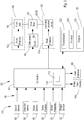
exemplary braking system 80 ofvehicle 10 is illustrated inFIG. 3 .Braking system 80 includesfront brakes 102 coupled tofront axle 54 offront axle assembly 50 andrear brakes 104 coupled to at least one ofrear axles bogie axle assembly 52. In one embodiment, twofront brakes front axle 54 for applying a braking force tofront axle 54, and arear brake 104 is coupled to firstrear axle 58 for applying a braking force to bothrear axles FIG. 2 . In particular,rear brake 104 coupled to firstrear axle 58 may apply braking torque to secondrear axle 60 throughdrive shaft 56.Front axle 54 andrear axles brakes brakes - Referring to
FIG. 3 ,controller 82 ofbraking system 80 is configured to controlbrakes Controller 82 is configured to controlbrakes brake input device 100. In one embodiment,brake input device 100 includes a pedal or lever, but may include other suitable input devices for applying a brake.Controller 82 controls inter-axle differential 64 anddifferential lock 94 based on various vehicle parameters and user inputs, as described herein.Controller 82 may also control the operation ofdifferentials FIG. 2 .Controller 82 may be a vehicle control unit ofvehicle 10, but may alternatively be a separate controller from the vehicle control unit. In the illustrated embodiment,controller 82 includes aprocessor 110 havingmemory 112 containing software configured to analyze inputs from various vehicle sensors for controlling differential 64. - As illustrated in
FIG. 3 , auser interface 85 may be provided for the operator to accesscontroller 82, for example, to modify settings or to enter instructions.User interface 85 may be of conventional design, such as a keypad or control panel, and may be positioned withincab 30.User interface 85 may include a display for providing an operator with vehicle information, such as vehicle speed, diagnostics, differential feedback, sensor information, or other vehicle parameters. - In one embodiment, when
vehicle 10 is positioned on an incline or slope withfront wheel assembly 32 positioned higher thanrear wheel assembly 33,vehicle 10 may experience a weight transfer towardsrear wheels vehicle 10 shifts towards the rear ofvehicle 10 whenvehicle 10 is positioned on a slope with the back oftrailer portion 16 facing down the slope. This weight transfer may cause reduced traction offront wheels front axle 54 andfront wheels front brake 102 tofront axle 54 results in a front axle braking force applied to the ground withwheels vehicle 10 is inclined up a slope due to reduced traction ofwheels - In the illustrated embodiment,
braking system 80 is configured to provide additional braking capacity tovehicle 10 in certain operating conditions. In particular,braking system 80 is configured to transfer braking torque fromfront axle assembly 50 tobogie axle assembly 52 whenvehicle 10 is reversing down a slope and whenvehicle 10 is substantially stopped at an incline on a slope, as described herein. To achieve additional braking capacity tobogie axle assembly 52,controller 82 is configured to automatically engagedifferential lock 94 of differential 64 based on various control inputs to transfer braking torque fromfront axle assembly 50 tobogie axle assembly 52. By locking differential 64, first andsecond portions drive shaft 56 are locked to rotate together. As such, braking force applied tofront axle 54 is configured to transfer torear axles drive shaft 56. - In one embodiment, lock 94 comprises a clutch assembly. In one embodiment, the amount of braking torque transferred from
front axle assembly 50 tobogie axle assembly 52 withlock 94 engaged may be limited to the frictional holding capacity of the clutch oflock 94. In particular, the maximum front axle braking torque transferred bydrive shaft 56 tobogie axle assembly 52 may limited to the maximum frictional holding force capacity of the clutch plates oflock 94. - In the illustrated embodiment,
controller 82 causes the automatic engagement ofdifferential lock 94 based oninputs 96 fromvehicle sensors 114.Inputs 96 may include the driving direction ofvehicle 10, the speed ofvehicle 10, the slope of the ground, the position ofbrake input device 100, the applied brake pressure, and/or the weight distribution ofvehicle 10. Fewer oradditional inputs 96 may be provided tocontroller 82 for controlling differential 64. In the illustrated embodiment,sensors 114 include aspeed sensor 83, adirection sensor 84, aslope sensor 86, abrake position sensor 88, and abrake pressure sensor 90 in communication withcontroller 82. In one embodiment,sensors 114 further include one ormore weight sensors 92 for detecting the weight distribution ofvehicle 10. -
Speed sensor 83 is configured to measure the speed ofvehicle 10 and provide a signal tocontroller 82 representative of the measured speed.Speed sensor 83 may measure the wheel speed, transmission speed, and/or engine speed ofvehicle 10.Direction sensor 84 detects forward or reverse movement ofvehicle 10 and provides a signal tocontroller 82 indicative of the detected moving direction ofvehicle 10. In one embodiment,direction sensor 84 andspeed sensor 83 are provided with a single sensor. In one embodiment,speed sensor 83 includes a variable reluctance or Hall effect sensor, but anysuitable sensor 83 for detecting speed and/or direction may be used. -
Slope sensor 86 is configured to measure the slope of the ground under vehicle 10 (i.e., the inclination angle of vehicle 10) and provide a signal representative of the measured ground slope tocontroller 82.Slope sensor 86 may comprise a conventional inclinometer or another suitable slope angle sensor. Brakeposition sensor 88 is configured to provide a signal tocontroller 82 representative of the position ofbrake input device 100. For example,brake position sensor 88 may include a conventional potentiometer coupled to a foot pedal or lever ofbrake input device 100 to measure the travel distance ofbrake input device 100. Other suitablebrake position sensors 88 may also be used.Brake pressure sensor 90 is configured to measure the brake pressure applied byfront brakes 102 and/orrear brakes 104 and to provide a signal or signals representative of the measured brake pressures tocontroller 82. - Fewer or
additional sensors 114 may provideinputs 96 tocontroller 82 for controlling differential 64 anddifferential lock 94. For example,brake system 80 may further include one ormore weight sensors 92 for measuring the weight supported byfront wheel assembly 32 and/orrear wheel assembly 33. In one embodiment, aweight sensor 92 is coupled to each of left and rightrear wheel assemblies rear wheel assembly controller 82.Trailer portion 16 and any load contained therein may contribute to the measured weight atrear wheel assembly 33. In some conditions, the weight ofcab portion 12 may also contribute to the weight onwheel assemblies - In one embodiment, each
weight sensor 92 includes a strain gauge mounted to a structure ofrear wheel assembly 33, such aswalking beam 44, for example, for detecting the weight ofvehicle 10. See, for example,weight sensor 92 mounted to walkingbeam 44 illustrated inFIG. 6 . Referring toFIG. 6 , strain gauge orweight sensor 92 is positioned in acavity 65 located in atop surface 45 ofwalking beam 44. In the illustrated embodiment,sensor 92 andcavity 65 are positioned near a center portion ofwalking beam 44 and aboveshaft 46 for detecting the load onbeam 44, althoughsensor 92 may be positioned in other suitable positions. Acover 67 is provided incavity 65 to substantially enclosesensor 92 withincavity 65. In one embodiment, a seal is provided betweencover 67 and thesurface forming cavity 65 to provide a sealed enclosure forsensor 92. Asensor cable 69 is configured to couplesensor 92 tocontroller 82 for providing feedback tocontroller 82. Alternatively,weight sensors 92 may include other suitable types and may be mounted at other locations suitable for measuring the weight supported byrear wheel assembly 33. - In one embodiment, one or
more weight sensors 92 are coupled tofront wheel assembly 32 for measuring weight supported byfront wheel assembly 32. In one embodiment, based on the input fromweight sensors 92,controller 82 may compare the measured weights onrear wheel assemblies front wheel assembly 32 to determine the weight distribution ofvehicle 10. - Referring to
FIG. 4 , an exemplary method of providing additional braking capacity tovehicle 10 is illustrated. The following describes the method ofFIG. 4 with reference tobraking system 80 ofFIG. 3 . Atblock 150,controller 82 determines the moving direction ofvehicle 10 withdirection sensor 84. Ifvehicle 10 is not moving in reverse,controller 82 determines atblock 160 whethervehicle 10 is stopped based on feedback fromspeed sensor 83. In one embodiment,vehicle 10 is considered stopped if the detected vehicle speed is substantially zero. Alternatively,vehicle 10 may be considered stopped atblock 160 ifvehicle 10 is moving at a minimal forward speed, for example, less than 3 miles per hour. Ifvehicle 10 is either moving in reverse or stopped,controller 82 determines atblock 152 ifvehicle 10 is positioned on an incline (i.e., iffront wheel assembly 32 is positioned vertically above rear wheel assembly 33). Ifvehicle 10 is positioned on an incline,controller 82 determines atblock 154 if the inclination angle ofvehicle 10 exceeds a minimum threshold angle. In one embodiment, the minimum threshold angle is three degrees. In one embodiment, the minimum threshold angle is five degrees. In one embodiment, the minimum threshold angle is ten degrees. Other suitable minimum threshold angles may be used. - If
vehicle 10 is positioned up a slope having an angle of inclination greater than the minimum threshold angle,controller 82 may determine atblock 156 if other conditions are met. For example,controller 82 may check the position ofbrake input device 100 withbrake position sensor 88 to determine if the operator has engaged the brakes. Ifbrake input device 100 is engaged or ifbrake input device 100 has moved a predetermined distance,controller 82 may proceed to block 158 to engagedifferential lock 94. In one embodiment,controller 82 may further check the brake pressure offront brakes 102 and/orrear brakes 104 atblock 156 and proceed to block 158 if the brake pressure exceeds a predetermined minimum brake pressure. In one embodiment,controller 82 may proceed directly to block 158 after determining atblock 154 thatvehicle 10 is positioned on a slope having an angle of inclination greater than the minimum threshold angle. - At
block 158,controller 82 engageslock 94 to lock differential 64, thereby lockingfirst portion 70 ofdrive shaft 56 tosecond portion 72 of drive shaft 56 (seeFIG. 2 ). As such, at least a portion of the front axle braking torque applied withfront brakes 102 transfers tobogie axle assembly 52 to provide increased braking capacity tovehicle 10. In one embodiment,controller 82 disengages lock 94 upon at least one of the conditions ofblocks controller 82 may disengagelock 94 uponvehicle 10 moving forward orvehicle 10 no longer being positioned on a slope having the minimum threshold angle. Other conditions may also causecontroller 82 to disengagelock 94. - In one embodiment,
controller 82 may be configured to modulate or vary the holding capacity oflock 94 by adjusting the position of the clutch plates oflock 94. For example,controller 82 may allow the clutch oflock 94 to slip to reduce the frictional holding capacity of thelock 94.Controller 82 may vary the holding capacity oflock 94 based on various vehicle parameters. - In one embodiment, the weight supported by
rear wheel assembly 33 and/orfront wheel assembly 32 is calculated and considered bycontroller 82 in initiating the engagement ofdifferential lock 94. For example, the minimum inclination angle required to engagelock 94 may be reduced when a larger vehicle payload is detected withweight sensors 92. In one embodiment,controller 82 may provide a stronger holding capacity withlock 94 when a larger payload is detected and a weaker holding capacity withlock 94 when a smaller payload is detected. - Referring to
FIGS. 5A and 5B , an exemplary braking force response is illustrated.FIGS. 5A and 5B each illustrate an exemplary brake holding force (measured in kilo-Newtons) of front andrear axles vehicle 10. In other words,FIGS. 5A and 5B illustrate the braking torque transferred to the ground by front andrear brakes FIGS. 5A and 5B ,vehicle 10 is positioned up the slope such thatfront wheel assembly 32 is positioned vertically above rear wheel assembly 33 (i.e., the back oftrailer portion 16 faces down the slope). In the illustrated embodiment, the tire traction coefficient of friction is 0.5. - Curve 180 of
FIGS. 5A and 5B illustrates the brake holding force required to holdvehicle 10 stationary on the slope.Curve 184 ofFIGS. 5A and 5B illustrates the brake holding force provided withfront axle 54 to the ground. In particular,curve 184 illustrates the brake holding force transferred to the ground throughfront axle 54 with the engagement ofbrakes 102. As illustrated bycurve 184, the potential brake holding force provided throughfront axle 54 is less than the required brake holding force forvehicle 10 for all slope levels. -
Curve 182 ofFIG. 5A illustrates an exemplary actual brake holding force applied to the ground with front andrear axles differential lock 94 of differential 64 is in an unlocked or disengaged state. In particular,curve 182 illustrates the combined brake holding force transferred to the ground throughfront axle 54 withbrakes 102 and throughrear axles brake 104. Curve 182' ofFIG. 5B illustrates an exemplary actual brake holding force applied to the ground with front andrear axles differential lock 94 of differential 64 is in a locked or engaged state. In particular, curve 182' illustrates the combined brake holding force transferred to the ground when the braking force offront brakes 102 is transferred fromfront axle 54 torear axles drive shaft 56. - Referring to
FIG. 5A , whendifferential lock 94 is disengaged, the actualbrake holding force 182 begins to deviate from the required braking force 180 at about a 30% slope and maxes out at about a 40% slope. Referring toFIG. 5B , whendifferential lock 94 is engaged, the actual brake holding force 182' transferred to the ground provides the required holding force 180 for ground slopes ranging from about 10% slope to about 50% slope before beginning to deviate from the required holding force 180 at about a 50% slope. As such, the engagement ofdifferential lock 94 whilevehicle 10 is positioned up a slope provides increased braking capacity tovehicle 10, particularly at slopes greater than 30%, as illustrated by curve 182' ofFIG. 5B . - In one embodiment, lock 94 is automatically engaged when
vehicle 10 is traveling down a slope. In particular,controller 82 may automatically engagelock 94 upon detection ofvehicle 10 moving down a slope in either a forward or reverse direction. In one embodiment,controller 82 may automatically engagelock 94 upon detection ofvehicle 10 moving in a reverse direction. -
Braking system 80 may further includeadditional speed retarders 120 for slowing orbraking vehicle 10, as illustrated inFIG. 3 . For example, atransmission retarder 122 may be configured to slow the rotational speed of transmission 51 (seeFIG. 2 ) under certain vehicle operating conditions.Transmission retarder 122 may include a hydrodynamic retarder and/or an electromagnetic retarder. Anexhaust brake 124 and/or anengine braking system 126 may be further implemented inbraking system 80 to facilitate speed reduction ofvehicle 10. For example,exhaust brake 124 may include a valve, such as a butterfly valve, mounted in the exhaust ofvehicle 10 for restricting airflow and slowingengine 31.Engine brake 126 may include an engine valve brake configured to increase compression inengine 31 to slowengine 31. In one embodiment,transmission retarder 122,exhaust brake 124, and/or theengine braking system 126 may be deactivated or ineffective whenvehicle 10 is moving at a slow speed. - While
braking system 80 is described herein with respect to articulatedvehicle 10,braking system 80 may be implemented on other types of vehicles. For example,braking system 80 may be implemented in other work or utility vehicles such as a motor grader, a tractor, a bulldozer, a feller buncher, a crawler, an excavator, a skidder, or another utility vehicle. Similarly,braking system 80 may also be implemented in a commercial vehicle or other roadworthy motor vehicles. - While this invention has been described as having preferred designs, the present invention can be further modified within the spirit and scope of this disclosure. This application is therefore intended to cover any variations, uses, or adaptations of the invention using its general principles. Further, this application is intended to cover such departures from the present disclosure as come within known or customary practice in the art to which this disclosure pertains and which fall within the limits of the appended claims.
Claims (16)
- A work vehicle including:a chassis (11);a front wheel assembly (32) coupled to the chassis (11) to support the chassis (11), the front wheel assembly (32) including a front axle (54) and a pair of wheels (34) coupled to the front axle (54);a rear wheel assembly (33) coupled to the chassis (11) to support the chassis (11), the rear wheel assembly (33) including at least one rear axle (58, 60) and a pair of wheels (40, 42) coupled to the rear axle (58, 60);a front brake (102) coupled to the front wheel assembly (32) and configured to apply a braking torque to the front wheel assembly (32) to inhibit rotation of the front axle (54);a detection means for detecting an operating condition of the vehicle (10);a transfer means for transferring a braking torque from the front wheel assembly (32) to the rear wheel assembly (33); anda means for activating the transfer means upon detection of the operating condition by the detection means.
- The work vehicle of claim 1, wherein the transfer means includes a drive shaft (56) and a differential (64) coupled to the drive shaft (56), the drive shaft (56) being coupled between the front wheel assembly (32) and the rear wheel assembly (33), the differential (64) including a lock device (94) configured to substantially block operation of the differential (64), and wherein the means for activating the transfer means includes a means for activating the lock device (94) of the differential (64).
- The work vehicle of claim 2, wherein the means for activating the transfer means includes a controller (82) having a processor (110), the controller (82) being in communication with the detection means and the transfer means.
- The work vehicle of claim 3, wherein the detection means includes a direction sensor (84) configured to detect a moving direction of the vehicle (10) and the controller (82) being configured to engage the lock device (94) upon detection of the vehicle moving in a reverse direction.
- The work vehicle of one of the claims 3 or 4, wherein the detection means includes a slope sensor (86) in communication with the controller (82), the slope sensor (86) being configured to detect a slope of the ground, the controller (82) being configured to engage the lock device (94) further upon detection of the vehicle reversing down a slope.
- The work vehicle of claim 5, wherein the slope sensor (86) is configured to detect an inclination angle of the vehicle (10), wherein the controller (82) engages the lock device (94) upon detection that the front wheel assembly (32) is higher than the rear wheel assembly (33) based on the inclination angle.
- The work vehicle of claim 6, wherein the controller (82) engages the lock device (94) further upon the inclination angle being outside a threshold range.
- The work vehicle of claim 7, wherein the threshold range includes angles of less than a maximum inclination angle.
- The work vehicle of one of the claims 3 to 8, wherein the drive shaft (56) including a first portion (70) coupled between the front wheel assembly (32) and the differential (64) and a second portion (72) coupled between the rear wheel assembly (33) and the differential (64), wherein engagement of the lock device (94) causes the first portion (70) and the second portion (72) of the drive shaft (56) to rotate together.
- The work vehicle of claim 9, wherein an application of the front brake (102) is configured to apply braking torque to the front wheel assembly (32) and to the rear wheel assembly (33) when the lock device (94) of the differential (64) is activated.
- The work vehicle of one of the claims 4 to 10, wherein the direction sensor (84) comprises a speed sensor (83) configured to detect a speed and the moving direction of the vehicle (10).
- The work vehicle of one the claims 3 to 11, further including a brake input device (100) and wherein the detection means including a brake position sensor (88), the brake input device (100) being configured to provide an input to the controller (82) to cause an actuation of the front brake (102), the brake position sensor (88) being configured to detect a position of the brake input device (100), the controller (82) engaging the lock device (94) further upon the brake input device (100) moving to a predetermined position.
- The work vehicle of one of the claims 3 to 12, where the detection means further including a brake pressure sensor (90) configured to detect the brake pressure of the front brake (102), the controller (82) engaging the lock device (94) further upon the detected brake pressure being outside a predetermined brake pressure range.
- The work vehicle of one of the claims 3 to 13, wherein the detection means further including at least one weight sensor (92) configured to measure weight supported by the front and rear wheel assemblies (32, 33), the controller (82) being configured to calculate a weight distribution of the vehicle (10) on the front and rear wheel assemblies (32, 33) based on the measured weight supported by the front and rear wheel assemblies (32, 33), the controller (82) being configured to engage the lock device (94) further upon the calculated weight distribution being outside a threshold weight distribution range.
- The vehicle of one of the claims 1 to 14, wherein the chassis (11) further includes a cab portion (12), a trailer portion (16), and a coupling assembly (20) positioned between the cab portion (12) and the trailer portion (16), the cab portion (12) including a first frame (14) and the trailer portion (16) including a second frame (18), the coupling assembly (20) being configured to provide pivoting movement of the trailer portion (16) relative to the cab portion (12), the front wheel assembly (32) being coupled to the first frame (14) and the rear wheel assembly (33) being coupled to the second frame (18).
- The vehicle of one of the claims 2 to 15, wherein the lock device (94) comprises a clutch assembly.
Applications Claiming Priority (1)
| Application Number | Priority Date | Filing Date | Title |
|---|---|---|---|
| US13/027,966 US8312956B2 (en) | 2011-02-15 | 2011-02-15 | Auto inter-axle differential lock engagement for improved braking capacity |
Publications (2)
| Publication Number | Publication Date |
|---|---|
| EP2489539A1 true EP2489539A1 (en) | 2012-08-22 |
| EP2489539B1 EP2489539B1 (en) | 2013-09-04 |
Family
ID=45655449
Family Applications (1)
| Application Number | Title | Priority Date | Filing Date |
|---|---|---|---|
| EP12154464.7A Not-in-force EP2489539B1 (en) | 2011-02-15 | 2012-02-08 | Auto inter-axle differential lock engagement for improved braking capacity |
Country Status (3)
| Country | Link |
|---|---|
| US (1) | US8312956B2 (en) |
| EP (1) | EP2489539B1 (en) |
| BR (1) | BR102012003416B1 (en) |
Cited By (5)
| Publication number | Priority date | Publication date | Assignee | Title |
|---|---|---|---|---|
| EP2832576A1 (en) * | 2013-07-30 | 2015-02-04 | ArvinMeritor Technology, LLC | Method of controlling a differential lock |
| BE1023474B1 (en) * | 2016-02-17 | 2017-04-03 | Van Hool Nv | Articulated vehicle in which the traction torque is distributed over the different driven axles |
| WO2017153160A1 (en) * | 2016-03-07 | 2017-09-14 | Jaguar Land Rover Limited | Braking control system |
| CN107272658A (en) * | 2017-07-25 | 2017-10-20 | 山推工程机械股份有限公司 | A kind of efficiency monitoring device, bull-dozer power assembly and bull-dozer |
| CN108628312A (en) * | 2018-05-14 | 2018-10-09 | 珠海市微半导体有限公司 | Robot is by the control method and chip of the detection method of card and off card |
Families Citing this family (16)
| Publication number | Priority date | Publication date | Assignee | Title |
|---|---|---|---|---|
| US9254728B2 (en) * | 2008-05-15 | 2016-02-09 | Oxbo International Corporation | Suspension system with a floating axle lock |
| US9651138B2 (en) | 2011-09-30 | 2017-05-16 | Mtd Products Inc. | Speed control assembly for a self-propelled walk-behind lawn mower |
| US9242556B2 (en) * | 2013-03-12 | 2016-01-26 | Dana Heavy Vehicle Systems Group, Llc | Transaxle with tandem axle |
| EP2949507A1 (en) * | 2014-05-29 | 2015-12-02 | Caterpillar SARL | Vehicle and method of controlling a vehicle |
| WO2016085369A1 (en) * | 2014-11-28 | 2016-06-02 | Volvo Construction Equipment Ab | A method and control unit for preventing rollover of a tractor unit of a working machine |
| US10094704B2 (en) | 2015-10-30 | 2018-10-09 | Caterpillar Inc. | System for estimating a mass of a payload in a hauling machine |
| US10710872B2 (en) | 2016-12-13 | 2020-07-14 | Taiwan Semiconductor Manufacturing Co., Ltd. | MEMS package with roughend interface |
| US10948064B2 (en) | 2017-06-09 | 2021-03-16 | Volvo Truck Corporation | Method for controlling a differential braking arrangement |
| US10926633B2 (en) | 2018-11-28 | 2021-02-23 | Dana Heavy Vehicle Systems Group, Llc | Method of controlling a tandem axle assembly |
| DE102019204129A1 (en) * | 2019-03-26 | 2020-10-01 | Zf Friedrichshafen Ag | Method for controlling a driving dynamics function of a work machine |
| US11607956B2 (en) * | 2019-10-31 | 2023-03-21 | Deere & Company | Trailing vehicle traction control system with a disconnect device |
| US11662245B2 (en) * | 2020-04-09 | 2023-05-30 | Caterpillar Inc. | Payload measurement system for machine with hauling body |
| US11396919B2 (en) * | 2020-12-30 | 2022-07-26 | Dana Heavy Vehicle Systems Group, Llc | Control and diagnostic method for a differential system |
| US11148529B1 (en) | 2021-02-11 | 2021-10-19 | Dana Heavy Vehicle Systems Group, Llc | System and method for controlling traction of tandem axles |
| US11691612B2 (en) | 2021-02-12 | 2023-07-04 | Dana Heavy Vehicle Systems Group, Llc | Systems and methods for disconnecting tandem axles |
| US11808342B2 (en) | 2022-02-08 | 2023-11-07 | Dana Automotive Systems Group, Llc | Differential carrier |
Citations (3)
| Publication number | Priority date | Publication date | Assignee | Title |
|---|---|---|---|---|
| EP0438176A1 (en) * | 1990-01-19 | 1991-07-24 | Mazda Motor Corporation | Differential control system for four-wheel drive vehicle |
| US20010027144A1 (en) * | 2000-03-29 | 2001-10-04 | Komatsu Ltd. | Control method of inter-axle differential and inter-axle differential apparatus |
| EP1179464A2 (en) * | 2000-07-31 | 2002-02-13 | Toyota Jidosha Kabushiki Kaisha | Brake control apparatus for four wheel drive vehicles |
Family Cites Families (16)
| Publication number | Priority date | Publication date | Assignee | Title |
|---|---|---|---|---|
| US2922482A (en) * | 1954-08-20 | 1960-01-26 | Fisher Andrew | Four wheel driven and steered tractor |
| US5995895A (en) * | 1997-07-15 | 1999-11-30 | Case Corporation | Control of vehicular systems in response to anticipated conditions predicted using predetermined geo-referenced maps |
| JP4014016B2 (en) * | 1997-10-24 | 2007-11-28 | 富士重工業株式会社 | Differential restriction control device for four-wheel drive vehicle |
| JP3687827B2 (en) * | 1997-11-08 | 2005-08-24 | アイシン精機株式会社 | Brake control device for vehicle |
| US6085138A (en) * | 1998-11-12 | 2000-07-04 | Caterpillar Inc. | Differential lock control system |
| JP4030082B2 (en) * | 1999-04-19 | 2008-01-09 | 株式会社小松製作所 | Articulated dump truck rear body fall prevention device |
| GB0018509D0 (en) * | 2000-07-27 | 2000-09-13 | Ricardo Mtc Limited | Vehicle transmission systems |
| JP2002087095A (en) * | 2000-09-12 | 2002-03-26 | Komatsu Ltd | Vehicle tire lock prevention device |
| DE10208239A1 (en) * | 2002-02-26 | 2003-09-04 | Zahnradfabrik Friedrichshafen | Device for automatic control of a differential lock |
| US7211017B2 (en) | 2002-11-06 | 2007-05-01 | Dana Corporation | Inter-axle differential lock shift mechanism |
| US7770909B2 (en) * | 2005-07-21 | 2010-08-10 | Deere & Company | Articulated vehicle stabilization system |
| US8082088B2 (en) * | 2005-09-20 | 2011-12-20 | Volvo Construction Equipment Ab | Method for controlling rotation speed |
| US7766104B2 (en) * | 2006-04-20 | 2010-08-03 | Caterpillar Inc | Differential lock control in articulated machine |
| EP2139714B1 (en) * | 2007-03-21 | 2012-10-17 | Volvo Construction Equipment AB | A power transmission arrangement |
| US7770681B2 (en) * | 2007-04-11 | 2010-08-10 | Caterpillar Inc | Traction control method in machine using lockable differential |
| WO2011137238A2 (en) * | 2010-04-30 | 2011-11-03 | American Axle & Manufacturing Inc. | Control strategy for operating a locking differential |
-
2011
- 2011-02-15 US US13/027,966 patent/US8312956B2/en active Active
-
2012
- 2012-02-08 EP EP12154464.7A patent/EP2489539B1/en not_active Not-in-force
- 2012-02-15 BR BR102012003416-6A patent/BR102012003416B1/en active IP Right Grant
Patent Citations (3)
| Publication number | Priority date | Publication date | Assignee | Title |
|---|---|---|---|---|
| EP0438176A1 (en) * | 1990-01-19 | 1991-07-24 | Mazda Motor Corporation | Differential control system for four-wheel drive vehicle |
| US20010027144A1 (en) * | 2000-03-29 | 2001-10-04 | Komatsu Ltd. | Control method of inter-axle differential and inter-axle differential apparatus |
| EP1179464A2 (en) * | 2000-07-31 | 2002-02-13 | Toyota Jidosha Kabushiki Kaisha | Brake control apparatus for four wheel drive vehicles |
Cited By (8)
| Publication number | Priority date | Publication date | Assignee | Title |
|---|---|---|---|---|
| EP2832576A1 (en) * | 2013-07-30 | 2015-02-04 | ArvinMeritor Technology, LLC | Method of controlling a differential lock |
| US9162569B2 (en) | 2013-07-30 | 2015-10-20 | Arvinmeritor Technology, Llc | Method of controlling a differential lock |
| BE1023474B1 (en) * | 2016-02-17 | 2017-04-03 | Van Hool Nv | Articulated vehicle in which the traction torque is distributed over the different driven axles |
| WO2017153160A1 (en) * | 2016-03-07 | 2017-09-14 | Jaguar Land Rover Limited | Braking control system |
| AU2017229136B2 (en) * | 2016-03-07 | 2019-07-18 | Jaguar Land Rover Limited | Braking control system |
| US10988121B2 (en) | 2016-03-07 | 2021-04-27 | Jaguar Land Rover Limited | Braking control system |
| CN107272658A (en) * | 2017-07-25 | 2017-10-20 | 山推工程机械股份有限公司 | A kind of efficiency monitoring device, bull-dozer power assembly and bull-dozer |
| CN108628312A (en) * | 2018-05-14 | 2018-10-09 | 珠海市微半导体有限公司 | Robot is by the control method and chip of the detection method of card and off card |
Also Published As
| Publication number | Publication date |
|---|---|
| EP2489539B1 (en) | 2013-09-04 |
| US20120205182A1 (en) | 2012-08-16 |
| US8312956B2 (en) | 2012-11-20 |
| BR102012003416A2 (en) | 2014-04-22 |
| BR102012003416B1 (en) | 2020-09-29 |
Similar Documents
| Publication | Publication Date | Title |
|---|---|---|
| US8312956B2 (en) | Auto inter-axle differential lock engagement for improved braking capacity | |
| US8708072B2 (en) | Modulated vehicle retardation system and method | |
| US8733489B2 (en) | Vehicle overspeed protection system | |
| US9086104B2 (en) | System and method for controlling wheel spin and wheel slip on a machine having differentially driven wheels | |
| EP2729333B1 (en) | Method of and apparatus for braking a tractor-trailer combination | |
| JP5492186B2 (en) | Traction control method and device for vehicles with individual drive mechanisms | |
| EP2729334B1 (en) | Method of and apparatus for braking a tractor-trailer combination | |
| US20140039772A1 (en) | Work Machine Drive Train Torque Vectoring Based on Work Cycle Recognition | |
| US8491064B2 (en) | Method and a system for braking a vehicle | |
| CN109963757A (en) | Method for controlling braking force of construction machinery | |
| US7966117B2 (en) | Method for controlling rotation speed | |
| EP3157771B1 (en) | A method for determining whether or not ground contact loss is imminent for a wheel of a vehicle. | |
| US7997350B2 (en) | Motor grader and clutch-control method for motor grader | |
| WO2016085369A1 (en) | A method and control unit for preventing rollover of a tractor unit of a working machine | |
| EP2433839B1 (en) | Method for a stability control of a trailer | |
| GB2414525A (en) | Vehicle differential control | |
| US20120209485A1 (en) | Machine control system utilizing inertial yaw sensor | |
| GB2414217A (en) | Vehicle differential control | |
| JP2826113B2 (en) | 4 wheel drive vehicle |
Legal Events
| Date | Code | Title | Description |
|---|---|---|---|
| PUAI | Public reference made under article 153(3) epc to a published international application that has entered the european phase |
Free format text: ORIGINAL CODE: 0009012 |
|
| AK | Designated contracting states |
Kind code of ref document: A1 Designated state(s): AL AT BE BG CH CY CZ DE DK EE ES FI FR GB GR HR HU IE IS IT LI LT LU LV MC MK MT NL NO PL PT RO RS SE SI SK SM TR |
|
| AX | Request for extension of the european patent |
Extension state: BA ME |
|
| 17P | Request for examination filed |
Effective date: 20130222 |
|
| GRAP | Despatch of communication of intention to grant a patent |
Free format text: ORIGINAL CODE: EPIDOSNIGR1 |
|
| RIC1 | Information provided on ipc code assigned before grant |
Ipc: B60K 28/16 20060101ALI20130315BHEP Ipc: B60K 23/08 20060101AFI20130315BHEP |
|
| INTG | Intention to grant announced |
Effective date: 20130411 |
|
| GRAS | Grant fee paid |
Free format text: ORIGINAL CODE: EPIDOSNIGR3 |
|
| GRAA | (expected) grant |
Free format text: ORIGINAL CODE: 0009210 |
|
| AK | Designated contracting states |
Kind code of ref document: B1 Designated state(s): AL AT BE BG CH CY CZ DE DK EE ES FI FR GB GR HR HU IE IS IT LI LT LU LV MC MK MT NL NO PL PT RO RS SE SI SK SM TR |
|
| REG | Reference to a national code |
Ref country code: GB Ref legal event code: FG4D |
|
| REG | Reference to a national code |
Ref country code: CH Ref legal event code: EP |
|
| REG | Reference to a national code |
Ref country code: AT Ref legal event code: REF Ref document number: 630281 Country of ref document: AT Kind code of ref document: T Effective date: 20130915 |
|
| REG | Reference to a national code |
Ref country code: IE Ref legal event code: FG4D |
|
| REG | Reference to a national code |
Ref country code: DE Ref legal event code: R096 Ref document number: 602012000255 Country of ref document: DE Effective date: 20131031 |
|
| REG | Reference to a national code |
Ref country code: SE Ref legal event code: TRGR |
|
| REG | Reference to a national code |
Ref country code: AT Ref legal event code: MK05 Ref document number: 630281 Country of ref document: AT Kind code of ref document: T Effective date: 20130904 |
|
| REG | Reference to a national code |
Ref country code: NL Ref legal event code: VDEP Effective date: 20130904 |
|
| PG25 | Lapsed in a contracting state [announced via postgrant information from national office to epo] |
Ref country code: CY Free format text: LAPSE BECAUSE OF FAILURE TO SUBMIT A TRANSLATION OF THE DESCRIPTION OR TO PAY THE FEE WITHIN THE PRESCRIBED TIME-LIMIT Effective date: 20130911 Ref country code: HR Free format text: LAPSE BECAUSE OF FAILURE TO SUBMIT A TRANSLATION OF THE DESCRIPTION OR TO PAY THE FEE WITHIN THE PRESCRIBED TIME-LIMIT Effective date: 20130904 Ref country code: NO Free format text: LAPSE BECAUSE OF FAILURE TO SUBMIT A TRANSLATION OF THE DESCRIPTION OR TO PAY THE FEE WITHIN THE PRESCRIBED TIME-LIMIT Effective date: 20131204 Ref country code: LT Free format text: LAPSE BECAUSE OF FAILURE TO SUBMIT A TRANSLATION OF THE DESCRIPTION OR TO PAY THE FEE WITHIN THE PRESCRIBED TIME-LIMIT Effective date: 20130904 Ref country code: AT Free format text: LAPSE BECAUSE OF FAILURE TO SUBMIT A TRANSLATION OF THE DESCRIPTION OR TO PAY THE FEE WITHIN THE PRESCRIBED TIME-LIMIT Effective date: 20130904 |
|
| REG | Reference to a national code |
Ref country code: NL Ref legal event code: VDEP Effective date: 20130904 |
|
| REG | Reference to a national code |
Ref country code: LT Ref legal event code: MG4D |
|
| PG25 | Lapsed in a contracting state [announced via postgrant information from national office to epo] |
Ref country code: LV Free format text: LAPSE BECAUSE OF FAILURE TO SUBMIT A TRANSLATION OF THE DESCRIPTION OR TO PAY THE FEE WITHIN THE PRESCRIBED TIME-LIMIT Effective date: 20130904 Ref country code: FI Free format text: LAPSE BECAUSE OF FAILURE TO SUBMIT A TRANSLATION OF THE DESCRIPTION OR TO PAY THE FEE WITHIN THE PRESCRIBED TIME-LIMIT Effective date: 20130904 Ref country code: PL Free format text: LAPSE BECAUSE OF FAILURE TO SUBMIT A TRANSLATION OF THE DESCRIPTION OR TO PAY THE FEE WITHIN THE PRESCRIBED TIME-LIMIT Effective date: 20130904 Ref country code: GR Free format text: LAPSE BECAUSE OF FAILURE TO SUBMIT A TRANSLATION OF THE DESCRIPTION OR TO PAY THE FEE WITHIN THE PRESCRIBED TIME-LIMIT Effective date: 20131205 Ref country code: SI Free format text: LAPSE BECAUSE OF FAILURE TO SUBMIT A TRANSLATION OF THE DESCRIPTION OR TO PAY THE FEE WITHIN THE PRESCRIBED TIME-LIMIT Effective date: 20130904 |
|
| PG25 | Lapsed in a contracting state [announced via postgrant information from national office to epo] |
Ref country code: CY Free format text: LAPSE BECAUSE OF FAILURE TO SUBMIT A TRANSLATION OF THE DESCRIPTION OR TO PAY THE FEE WITHIN THE PRESCRIBED TIME-LIMIT Effective date: 20130904 Ref country code: BE Free format text: LAPSE BECAUSE OF FAILURE TO SUBMIT A TRANSLATION OF THE DESCRIPTION OR TO PAY THE FEE WITHIN THE PRESCRIBED TIME-LIMIT Effective date: 20130904 |
|
| PG25 | Lapsed in a contracting state [announced via postgrant information from national office to epo] |
Ref country code: EE Free format text: LAPSE BECAUSE OF FAILURE TO SUBMIT A TRANSLATION OF THE DESCRIPTION OR TO PAY THE FEE WITHIN THE PRESCRIBED TIME-LIMIT Effective date: 20130904 Ref country code: CZ Free format text: LAPSE BECAUSE OF FAILURE TO SUBMIT A TRANSLATION OF THE DESCRIPTION OR TO PAY THE FEE WITHIN THE PRESCRIBED TIME-LIMIT Effective date: 20130904 Ref country code: RO Free format text: LAPSE BECAUSE OF FAILURE TO SUBMIT A TRANSLATION OF THE DESCRIPTION OR TO PAY THE FEE WITHIN THE PRESCRIBED TIME-LIMIT Effective date: 20130904 Ref country code: NL Free format text: LAPSE BECAUSE OF FAILURE TO SUBMIT A TRANSLATION OF THE DESCRIPTION OR TO PAY THE FEE WITHIN THE PRESCRIBED TIME-LIMIT Effective date: 20130904 Ref country code: IS Free format text: LAPSE BECAUSE OF FAILURE TO SUBMIT A TRANSLATION OF THE DESCRIPTION OR TO PAY THE FEE WITHIN THE PRESCRIBED TIME-LIMIT Effective date: 20140104 Ref country code: SK Free format text: LAPSE BECAUSE OF FAILURE TO SUBMIT A TRANSLATION OF THE DESCRIPTION OR TO PAY THE FEE WITHIN THE PRESCRIBED TIME-LIMIT Effective date: 20130904 |
|
| PG25 | Lapsed in a contracting state [announced via postgrant information from national office to epo] |
Ref country code: ES Free format text: LAPSE BECAUSE OF FAILURE TO SUBMIT A TRANSLATION OF THE DESCRIPTION OR TO PAY THE FEE WITHIN THE PRESCRIBED TIME-LIMIT Effective date: 20130904 |
|
| REG | Reference to a national code |
Ref country code: DE Ref legal event code: R097 Ref document number: 602012000255 Country of ref document: DE |
|
| PG25 | Lapsed in a contracting state [announced via postgrant information from national office to epo] |
Ref country code: PT Free format text: LAPSE BECAUSE OF FAILURE TO SUBMIT A TRANSLATION OF THE DESCRIPTION OR TO PAY THE FEE WITHIN THE PRESCRIBED TIME-LIMIT Effective date: 20140106 |
|
| PLBE | No opposition filed within time limit |
Free format text: ORIGINAL CODE: 0009261 |
|
| STAA | Information on the status of an ep patent application or granted ep patent |
Free format text: STATUS: NO OPPOSITION FILED WITHIN TIME LIMIT |
|
| 26N | No opposition filed |
Effective date: 20140605 |
|
| REG | Reference to a national code |
Ref country code: DE Ref legal event code: R119 Ref document number: 602012000255 Country of ref document: DE |
|
| REG | Reference to a national code |
Ref country code: DE Ref legal event code: R097 Ref document number: 602012000255 Country of ref document: DE Effective date: 20140605 |
|
| PG25 | Lapsed in a contracting state [announced via postgrant information from national office to epo] |
Ref country code: DK Free format text: LAPSE BECAUSE OF FAILURE TO SUBMIT A TRANSLATION OF THE DESCRIPTION OR TO PAY THE FEE WITHIN THE PRESCRIBED TIME-LIMIT Effective date: 20130904 Ref country code: LU Free format text: LAPSE BECAUSE OF FAILURE TO SUBMIT A TRANSLATION OF THE DESCRIPTION OR TO PAY THE FEE WITHIN THE PRESCRIBED TIME-LIMIT Effective date: 20140208 Ref country code: MC Free format text: LAPSE BECAUSE OF FAILURE TO SUBMIT A TRANSLATION OF THE DESCRIPTION OR TO PAY THE FEE WITHIN THE PRESCRIBED TIME-LIMIT Effective date: 20130904 |
|
| REG | Reference to a national code |
Ref country code: FR Ref legal event code: ST Effective date: 20141031 |
|
| REG | Reference to a national code |
Ref country code: IE Ref legal event code: MM4A |
|
| REG | Reference to a national code |
Ref country code: DE Ref legal event code: R119 Ref document number: 602012000255 Country of ref document: DE Effective date: 20140902 |
|
| PG25 | Lapsed in a contracting state [announced via postgrant information from national office to epo] |
Ref country code: FR Free format text: LAPSE BECAUSE OF NON-PAYMENT OF DUE FEES Effective date: 20140228 Ref country code: IE Free format text: LAPSE BECAUSE OF NON-PAYMENT OF DUE FEES Effective date: 20140208 Ref country code: DE Free format text: LAPSE BECAUSE OF NON-PAYMENT OF DUE FEES Effective date: 20140902 |
|
| REG | Reference to a national code |
Ref country code: CH Ref legal event code: PL |
|
| PG25 | Lapsed in a contracting state [announced via postgrant information from national office to epo] |
Ref country code: CH Free format text: LAPSE BECAUSE OF NON-PAYMENT OF DUE FEES Effective date: 20150228 Ref country code: LI Free format text: LAPSE BECAUSE OF NON-PAYMENT OF DUE FEES Effective date: 20150228 |
|
| PG25 | Lapsed in a contracting state [announced via postgrant information from national office to epo] |
Ref country code: MT Free format text: LAPSE BECAUSE OF FAILURE TO SUBMIT A TRANSLATION OF THE DESCRIPTION OR TO PAY THE FEE WITHIN THE PRESCRIBED TIME-LIMIT Effective date: 20130904 |
|
| PG25 | Lapsed in a contracting state [announced via postgrant information from national office to epo] |
Ref country code: SM Free format text: LAPSE BECAUSE OF FAILURE TO SUBMIT A TRANSLATION OF THE DESCRIPTION OR TO PAY THE FEE WITHIN THE PRESCRIBED TIME-LIMIT Effective date: 20130904 |
|
| PG25 | Lapsed in a contracting state [announced via postgrant information from national office to epo] |
Ref country code: BG Free format text: LAPSE BECAUSE OF FAILURE TO SUBMIT A TRANSLATION OF THE DESCRIPTION OR TO PAY THE FEE WITHIN THE PRESCRIBED TIME-LIMIT Effective date: 20130904 Ref country code: RS Free format text: LAPSE BECAUSE OF NON-PAYMENT OF DUE FEES Effective date: 20130904 |
|
| PG25 | Lapsed in a contracting state [announced via postgrant information from national office to epo] |
Ref country code: TR Free format text: LAPSE BECAUSE OF FAILURE TO SUBMIT A TRANSLATION OF THE DESCRIPTION OR TO PAY THE FEE WITHIN THE PRESCRIBED TIME-LIMIT Effective date: 20130904 Ref country code: HU Free format text: LAPSE BECAUSE OF FAILURE TO SUBMIT A TRANSLATION OF THE DESCRIPTION OR TO PAY THE FEE WITHIN THE PRESCRIBED TIME-LIMIT; INVALID AB INITIO Effective date: 20120208 |
|
| GBPC | Gb: european patent ceased through non-payment of renewal fee |
Effective date: 20160208 |
|
| PG25 | Lapsed in a contracting state [announced via postgrant information from national office to epo] |
Ref country code: GB Free format text: LAPSE BECAUSE OF NON-PAYMENT OF DUE FEES Effective date: 20160208 |
|
| PG25 | Lapsed in a contracting state [announced via postgrant information from national office to epo] |
Ref country code: MK Free format text: LAPSE BECAUSE OF FAILURE TO SUBMIT A TRANSLATION OF THE DESCRIPTION OR TO PAY THE FEE WITHIN THE PRESCRIBED TIME-LIMIT Effective date: 20130904 |
|
| PG25 | Lapsed in a contracting state [announced via postgrant information from national office to epo] |
Ref country code: AL Free format text: LAPSE BECAUSE OF FAILURE TO SUBMIT A TRANSLATION OF THE DESCRIPTION OR TO PAY THE FEE WITHIN THE PRESCRIBED TIME-LIMIT Effective date: 20130904 |
|
| PGFP | Annual fee paid to national office [announced via postgrant information from national office to epo] |
Ref country code: SE Payment date: 20240307 Year of fee payment: 13 Ref country code: IT Payment date: 20240222 Year of fee payment: 13 |
|
| REG | Reference to a national code |
Ref country code: SE Ref legal event code: EUG |
|
| PG25 | Lapsed in a contracting state [announced via postgrant information from national office to epo] |
Ref country code: IT Free format text: LAPSE BECAUSE OF NON-PAYMENT OF DUE FEES Effective date: 20250208 |