EP2489116B1 - Wireless control of power network switching devices - Google Patents
Wireless control of power network switching devices Download PDFInfo
- Publication number
- EP2489116B1 EP2489116B1 EP09784008.6A EP09784008A EP2489116B1 EP 2489116 B1 EP2489116 B1 EP 2489116B1 EP 09784008 A EP09784008 A EP 09784008A EP 2489116 B1 EP2489116 B1 EP 2489116B1
- Authority
- EP
- European Patent Office
- Prior art keywords
- slave
- data packets
- converter
- slave controller
- controller
- Prior art date
- Legal status (The legal status is an assumption and is not a legal conclusion. Google has not performed a legal analysis and makes no representation as to the accuracy of the status listed.)
- Active
Links
Images

Classifications
-
- H—ELECTRICITY
- H02—GENERATION; CONVERSION OR DISTRIBUTION OF ELECTRIC POWER
- H02M—APPARATUS FOR CONVERSION BETWEEN AC AND AC, BETWEEN AC AND DC, OR BETWEEN DC AND DC, AND FOR USE WITH MAINS OR SIMILAR POWER SUPPLY SYSTEMS; CONVERSION OF DC OR AC INPUT POWER INTO SURGE OUTPUT POWER; CONTROL OR REGULATION THEREOF
- H02M1/00—Details of apparatus for conversion
- H02M1/12—Arrangements for reducing harmonics from AC input or output
-
- H—ELECTRICITY
- H02—GENERATION; CONVERSION OR DISTRIBUTION OF ELECTRIC POWER
- H02M—APPARATUS FOR CONVERSION BETWEEN AC AND AC, BETWEEN AC AND DC, OR BETWEEN DC AND DC, AND FOR USE WITH MAINS OR SIMILAR POWER SUPPLY SYSTEMS; CONVERSION OF DC OR AC INPUT POWER INTO SURGE OUTPUT POWER; CONTROL OR REGULATION THEREOF
- H02M7/00—Conversion of AC power input into DC power output; Conversion of DC power input into AC power output
- H02M7/42—Conversion of DC power input into AC power output without possibility of reversal
- H02M7/44—Conversion of DC power input into AC power output without possibility of reversal by static converters
- H02M7/48—Conversion of DC power input into AC power output without possibility of reversal by static converters using discharge tubes with control electrode or semiconductor devices with control electrode
- H02M7/53—Conversion of DC power input into AC power output without possibility of reversal by static converters using discharge tubes with control electrode or semiconductor devices with control electrode using devices of a triode or transistor type requiring continuous application of a control signal
- H02M7/537—Conversion of DC power input into AC power output without possibility of reversal by static converters using discharge tubes with control electrode or semiconductor devices with control electrode using devices of a triode or transistor type requiring continuous application of a control signal using semiconductor devices only, e.g. single switched pulse inverters
- H02M7/5387—Conversion of DC power input into AC power output without possibility of reversal by static converters using discharge tubes with control electrode or semiconductor devices with control electrode using devices of a triode or transistor type requiring continuous application of a control signal using semiconductor devices only, e.g. single switched pulse inverters in a bridge configuration
- H02M7/53871—Conversion of DC power input into AC power output without possibility of reversal by static converters using discharge tubes with control electrode or semiconductor devices with control electrode using devices of a triode or transistor type requiring continuous application of a control signal using semiconductor devices only, e.g. single switched pulse inverters in a bridge configuration with automatic control of output voltage or current
-
- H—ELECTRICITY
- H03—ELECTRONIC CIRCUITRY
- H03K—PULSE TECHNIQUE
- H03K17/00—Electronic switching or gating, i.e. not by contact-making and –breaking
- H03K17/51—Electronic switching or gating, i.e. not by contact-making and –breaking characterised by the components used
- H03K17/78—Electronic switching or gating, i.e. not by contact-making and –breaking characterised by the components used using opto-electronic devices, i.e. light-emitting and photoelectric devices electrically- or optically-coupled
- H03K17/785—Electronic switching or gating, i.e. not by contact-making and –breaking characterised by the components used using opto-electronic devices, i.e. light-emitting and photoelectric devices electrically- or optically-coupled controlling field-effect transistor switches
Definitions
- the present invention is concerned with communication between a power electronics controller and a network of high-power semiconductor switching devices.
- it is concerned with wireless communication with a plurality of power converters, also known as electronic frequency converters and with synchronisation of said plurality of power converters.
- Electrical power networks are most often operated at a nominal and fixed voltage and frequency.
- the connection of certain types of equipment, such as for example generators, that output power with variable voltage and or frequency may be accomplished using electronic frequency converters also known as power converters.
- DTC Direct torque control
- PWM Pulse width modulated
- Power converters may be arranged to control a variable power output and convert it into an acceptable power input to a power network with fixed nominal characteristics.
- wind generators tend to have an electrical power output that varies with wind speed so that variation occurs in voltage and frequency of the generator output as wind speed varies.
- PWM power converters may arranged to control and switch such variable power supplies so that a resulting power input into a power network matches the nominal fixed voltage and frequency.
- WO 2006/039823 entitled "Signal transmission system for activating a power semiconductor switch, and a converter equipped with a signal transmission system of this type" assigned to ABB Research Ltd.
- WO 2006/039823 describes a signal transmission system which serves to activate at least one power semiconductor switch (S1, S2,, Sn) starting from a controller (11).
- At least one control signal can be transmitted from the controller (11) to at least one modulator (M1, M2, ..., Mn) via at least one first transmission path (3). It discloses that a wireless control signal and/or a drive signal to PWM power converters can be transmitted using an optical signal path.
- US2008284252 entitled “Control methods for the synchronization and phase shift of the pulse width modulation (PWM) strategy of power converters” and assigned to Converteam Tech. Ltd., describes a method of controlling a plurality of power converters 1 a, 1 b and 1 c can be used to interface to a supply network, ac busbar etc.
- Each power converter includes a network bridge 14 operating in accordance with a pulse width modulation (PWM) strategy having the same switching period.
- the method includes providing the switching period of each network bridge with a different time offset relative to a time datum such that at least one unwanted harmonic in the supply network voltage is at least partially cancelled. In other words, different timing signals are sent to different converters, and these timing signals are used to locally offset each converters clock.
- a technical challenge for such implementations is that communication between a controller and each converter requires a very fast communication link with latency of only some few microseconds ⁇ s .
- the local clock of each converter must be extremely accurate over a long period to maintain sufficient accuracy down to a few microseconds, which poses both technical issues and cost issues.
- US2006173565 A1 discloses a packaging apparatus, which is equipped with sensors, actuators and a drive system, including a servo motor, a central control unit and a system for data transmission.
- the actual values of the sensors, actuators and the drive system are recorded, in digital form, in each case, and transferred with the use of a transmission protocol by way of the data transmission system to the central control unit.
- the central control unit evaluates the data and the determined setpoint values or control commands, which are transmitted, in digital form, from the control unit by the data transmission system to the actuator or drive system.
- the data transmission between the sensors, actuators, drive system and the central control unit takes place wirelessly and the transmission protocol operates cyclically and with short cycle times, preferably in millisecond pulses.
- the transmission protocol serves for synchronization of all sensors, actuators and drives, prepares the actual values and the determined setpoint data of all drives in each cycle, the accuracy of the synchronization and the preparation lying in the microsecond range.
- EP1396739 A1 discloses a method, system, and apparatus are provided for detecting a position of a terminal in a network accurately without a GPS receiver.
- a method for locating a position of a terminal includes calculating a position of a base station, detecting a clock time difference between the base station and another base station; measuring a reception timing of a signal received by the base station from the terminal, and locating the position of the terminal using at least the position of the base station, the clock time difference, and the reception timing.
- US2003137856 A1 discloses a switching synchronization method of parallel converter system, wherein one of converters is the host and the others are slave converters.
- the host converter includes a first timer and a pulse-transmitting device
- the slave converter includes a second timer, pulse capture device, and a synchronization adjustment.
- Tkl the host converter sends a synchronization pulse to the synchronization bus through the pulse-transmitting device
- the second timer records the time Tx of the edge of the synchronization pulse received by the pulse capture device from the synchronization bus.
- the synchronization adjuster adjusts the second timer of the slave converter so as to synchronize it with the first timer of the host converter in accordance with the relationship between the times Tkl and Tx; and then according to a predetermined protocol, the switching carrier timer of the slave converter so as to be adjusted to synchronize with the switching carrier timer of the host converter.
- EP1995863 A2 discloses a method for controlling the synchronization of a plurality of power converters.
- the aim of the present invention is to remedy one or more of the above mentioned problems.
- This disclosure describes the use of wireless communication between a power electronics controller and a network of high-power semiconductor switching devices. Control decisions from a controller are transferred as wireless packets addressed to individual switches or groups of switches.
- the controller is called the master and an individual switching device or a group of switching devices is called a slave or a node.
- the wireless air interface and protocol is designed such that wireless packets may only be transmitted in precisely defined slots in periodically repeated timing frames. Packets may contain the slot number and may also contain more coarse timing information such as frame number. In this way, a common measure of time can be maintained in all the nodes with a timing resolution at least as good as the slot-border resolution built into the wireless air interface.
- Packets containing on/off switching decisions preferably also contain information about the point(s) in time in the future where switching is to take place.
- the control algorithm can have a significantly longer cycle time than the one required by the on/off timing resolution.
- a preferred use of an embodiment of the invention is to use wireless communication between a power electronics controller and a number of high-power switching devices, for example in a power converter devices.
- a power converter typically consists of a AC/DC module for example a rectifier, and one or more DC/AC modules for example inverters.
- Each rectifier or inverter contains high-power semiconductor devices, for example IGCTs (integrated gate-commutated thyristors) which can be turned on and off at will. High voltages and large currents are normally present.
- IGCTs integrated gate-commutated thyristors
- the control algorithm results in a sequence of decisions telling the individual switches (such as power converters) to turn on or off at specific points in time. Control decisions are transferred from the controller as wireless packets addressed to individual switches (eg converters) or groups of switches. Precise timing of the on/off control signals is imperative in order to minimize power losses and to avoid equipment damage caused by excessive currents. Required timing accuracy is in the range of 1 microsecond ⁇ s .
- wireless communication saves the cabling for the communication wires which are subject to ageing.
- Wireless communication also allows galvanic separation between the controllers and devices which are on high potential. It also facilitates reconfiguration of the power converter circuitry.
- a common measure of time for all of the nodes is established between the nodes and the controller.
- separating the precise timekeeping from the control algorithm timing, and utilizing the precise timing inherent to time-slotted wireless protocols, provides a technical solution that reduces the performance requirements on both the controller and the transaction timing of the wireless protocol.
- Figure 1 illustrates a known Pulse Width Modulation (PWM) method used in high power semiconductor devices such as power converters.
- PWM Pulse Width Modulation
- the figure shows a group of power converters 1' of a power network.
- a controller (not shown) generates two input signals 6 and 7.
- Signal 6 is a reference signal and corresponds to the desired voltage or current output from the converters when switched, typically a sinusoidal signal.
- Signal 7 is a carrier signal, typically a sawtooth signal.
- the figure shows the basic elements of generation by the power electronics controller.
- the controller generates the two signals -the reference signal 6, also called modulating signal s(t): It defines the desired waveform of the power converter output, which typically, is a sine wave of controllable frequency.
- the control parameters CP given from an external eg power network source to the controller specify this reference signal, and it includes
- a comparator 8 enters a comparator 8.
- the time instants t i when the carrier signal intersects the modulating signal determine the gate switching signals that will be generated under the control scheme, which could, for example, be PWM; at t i a gate switching command (also called 'on/off command', or 'firing pulse') is sent to the converter.
- the sequence of switching commands to the power electronic gates in the converter produces the desired power output.
- the time accuracy of the switching commands must be in the order of microseconds ⁇ s .
- Prior Art Op 1 is known from WO 2006/039823 discloses a centralised control signal calculation using a very high speed communication line.
- the master performs the PWM generation and transmits the switching commands directly to the slaves at the switching time t i . This is done in the centralized architecture (11, Figure 1 ), typically over optical fibre.
- This method may be called asynchronous, as it requires no synchronization of the slaves: the slave receives the command from the master at the exact time it must issue (forward) the actual switching command to the gates in its module.
- this Prior Art method requires a very fast communication link with latency of some microseconds ⁇ s .
- FIG. 2 shows an architecture concept according to an embodiment of the invention in the form of a modular converter 20 consisting of several converter modules 1-4.
- a master controller 10 transmits control signals to the slave controllers.
- a slave controller is co-located to a converter module 1-4 and is endowed with communication, as shown in Fig 2 as the wireless nodes N 1-4 , and processing capability, and each local or slave controller is preferably directly connected to the power electronics gates of its module.
- the power outputs of the converter modules are connected to achieve the desired total output power. Hence, the switching commands to the gates in all modules must be synchronized to the accuracy of some microseconds ⁇ s .
- Op 2 Option 2 encoded switching commands is described as follows.
- the master or controller 10 performs the PWM resulting in a value of t i . It encodes this value, or possibly several subsequent values, in a digital message and transmits the message to the slave N 1-4 .
- the slave issues the switching command to its gates at time t i , based on its local clock.
- the communication link may be slower, but it is required that the slaves synchronize their clocks to the accuracy of some microseconds ⁇ s . (There may be delay issues which make this option difficult.)
- Time division multiple access is the preferred communication protocol for wireless master to slaves communication. For each slave, a fixed periodic timeslots is allocated to the communication between the slave and the master. This guarantees deterministic behavior of the data transmission.
- TDMA Time division multiple access
- a wireless radio protocol from ABB called WISA (Wireless Interface for Sensors and Actuators) uses TDMA.
- WISA Wireless Interface for Sensors and Actuators
- - Options 2 to 4 require synchronization of the clocks in the slaves. [6] suggests to perform this synchronization by taking advantage of the timing implied in the TDMA protocol.
- the wireless air interface and protocol is designed such that wireless packets may only be transmitted in precisely defined slots on a periodically repeated timing frame or a timing grid. A defined number of slots build up a timing frame.
- the master (the controller) is the timing master. All or some of the packets from the master contain the slot number and may also contain more coarse timing information such as, for example, frame number.
- each node N 1-4 has a local timer and some processing capability.
- a node makes use of the timing information built into all wireless packets coming from the master, even those not addressed to the node itself. Every time a node detects a packet, it adjusts its internal timer. To maintain a desired timing resolution, the individual clock frequencies in the nodes must not be allowed to drift more than a defined amount in between such adjustments. This can be achieved by either more expensive clock crystal in the node, or more frequent adjustments in the form of packets from the master.
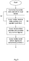
- Flowchart Figure 3 shows a series of actions for carrying out the method. It shows:
- Control packets need to contain control information for on/off switching as well as information about the point(s) in time in the near future when switching shall take place. Because precise timing can be maintained separately, as described above, the control loop cycle time needs only to support the on/off decision rate which is normally much more relaxed.
- An example of a wireless protocol is the above mentioned wireless radio protocol WISA - Wireless Interface to Sensors and Actuators from ABB.
- the WISA master transmits packets back-to-back almost continuously.
- the packets are either addressed to specific nodes, or dummy packets. It provides a timing resolution down to +/- 0.5 microseconds, whereas packets to any specific node can be transmitted in terms of milliseconds, for example every ⁇ 2ms.
- a communication may be arranged as shown by Op 3.
- Option 3 in Fig 2 describes transmission of reference signal (a type of distributed PWM 1): Samples of the reference signal S k are multicast periodically from the master or controller 10 to the slaves, say once per ms. Given this reference signal, each slave N 1-4 may use a locally generated carrier to determine the switching instant t i .
- the multicast communication link may be even slower, but again slave synchronization is required.
- Op 4 in which transmission of control parameters (distributed PWM 2)takes place: Where the reference signal can be described by some few and only slowly varying control parameters CP (such as the modulation index), the master controller may send these parameters over a slow communication link. PWM generation is then fully done in the slaves, which must be synchronized. The communication can be done on slow links, but this option is less flexible than option 3.
- the controller 10 may be connected to a node of a wireless LAN, and/or may be another kind of wireless node, running any radio protocol suitable for an industrial milieu, such as any standard issued by the Bluetooth Special Interest Group (SIG), any variation of IEEE-802.11, WiFi, Ultra Wide Band (UWB), ZigBee or IEEE-802.15.4, IEEE-802.13 or equivalent, or similar.
- a radio technology working in the ISM band with significant interference suppression means such as by spread spectrum technology may be preferred.
- Wireless communication may also be carried out using optical links, including for example Infra Red (IR) means and protocols such as IrDA, IrCOMM or similar.
- Wireless communication may also be carried out using a magnetic coupling or electrostatic coupling. Wireless IR communication may be carried out for example by an over the air method also referred to as diffuse IR.
- the methods of embodiments such as in Figure 3 as described above and elsewhere in this specification may be carried out by a computer application comprising computer program elements or software code which, when loaded in a processor or computer, causes the computer or processor to carry out the method steps.
- the functions of the methods for synchronising the clock and for processing the switching signals and producing the switching signals may be carried out by processing digital functions, algorithms and/or computer programs and/or by analogue components or analogue circuits or by a combination of both digital and analogue functions.
- the methods may be run using configurable hardware components such as one or more FPGA chips (Field Programmable Gate Array).
- Other types of hardware may also be used, such as a a Complex Programmable Logic Device (CPLD) or an Application Specific Integrated Circuit (ASIC) may be used.
- CPLD Complex Programmable Logic Device
- ASIC Application Specific Integrated Circuit
- the methods of the invention may, as previously described, be carried out by means of one or more computer programs comprising computer program code elements or software code portions that make the computer perform the method using equations, algorithms, data, stored values and calculations previously described.
- a part of the program may be stored in a processor as above, but also in a ROM, RAM, PROM, EPROM or EEPROM chip or similar memory means.
- the program in part or in whole may also be stored on, or in, other suitable computer readable medium such as a magnetic disk, CD-ROM or DVD disk, hard disk, magneto-optical memory storage means, in volatile memory, in flash memory, as firmware, stored on a data server or on one or more arrays of data servers.
- Other known and suitable media including removable memory media such as memory sticks and other removable flash memories, hard drives etc. may also be used.
Landscapes
- Engineering & Computer Science (AREA)
- Power Engineering (AREA)
- Mobile Radio Communication Systems (AREA)
- Synchronisation In Digital Transmission Systems (AREA)
- Remote Monitoring And Control Of Power-Distribution Networks (AREA)
- Inverter Devices (AREA)
Description
- The present invention is concerned with communication between a power electronics controller and a network of high-power semiconductor switching devices. In particular it is concerned with wireless communication with a plurality of power converters, also known as electronic frequency converters and with synchronisation of said plurality of power converters.
- Electrical power networks are most often operated at a nominal and fixed voltage and frequency. The connection of certain types of equipment, such as for example generators, that output power with variable voltage and or frequency may be accomplished using electronic frequency converters also known as power converters. There are different methods to generate gate switching signals to operate power converters, of which one known method is DTC (Direct torque control) and another well known method is PWM (Pulse width modulated). Power converters may be arranged to control a variable power output and convert it into an acceptable power input to a power network with fixed nominal characteristics. For example wind generators tend to have an electrical power output that varies with wind speed so that variation occurs in voltage and frequency of the generator output as wind speed varies. For example PWM power converters may arranged to control and switch such variable power supplies so that a resulting power input into a power network matches the nominal fixed voltage and frequency.
- A method for switching power converters is described in an international patent application
WO 2006/039823 entitled "Signal transmission system for activating a power semiconductor switch, and a converter equipped with a signal transmission system of this type" assigned to ABB Research Ltd.WO 2006/039823 describes a signal transmission system which serves to activate at least one power semiconductor switch (S1, S2,, Sn) starting from a controller (11). At least one control signal can be transmitted from the controller (11) to at least one modulator (M1, M2, ..., Mn) via at least one first transmission path (3). It discloses that a wireless control signal and/or a drive signal to PWM power converters can be transmitted using an optical signal path. -
US2008284252 , entitled "Control methods for the synchronization and phase shift of the pulse width modulation (PWM) strategy of power converters" and assigned to Converteam Tech. Ltd., describes a method of controlling a plurality of power converters 1 a, 1 b and 1 c can be used to interface to a supply network, ac busbar etc. Each power converter includes a network bridge 14 operating in accordance with a pulse width modulation (PWM) strategy having the same switching period. The method includes providing the switching period of each network bridge with a different time offset relative to a time datum such that at least one unwanted harmonic in the supply network voltage is at least partially cancelled. In other words, different timing signals are sent to different converters, and these timing signals are used to locally offset each converters clock. - A technical challenge for such implementations is that communication between a controller and each converter requires a very fast communication link with latency of only some few microseconds µs. Alternatively, the local clock of each converter must be extremely accurate over a long period to maintain sufficient accuracy down to a few microseconds, which poses both technical issues and cost issues.
-
US2006173565 A1 discloses a packaging apparatus, which is equipped with sensors, actuators and a drive system, including a servo motor, a central control unit and a system for data transmission. The actual values of the sensors, actuators and the drive system are recorded, in digital form, in each case, and transferred with the use of a transmission protocol by way of the data transmission system to the central control unit. The central control unit evaluates the data and the determined setpoint values or control commands, which are transmitted, in digital form, from the control unit by the data transmission system to the actuator or drive system. The data transmission between the sensors, actuators, drive system and the central control unit takes place wirelessly and the transmission protocol operates cyclically and with short cycle times, preferably in millisecond pulses. The transmission protocol serves for synchronization of all sensors, actuators and drives, prepares the actual values and the determined setpoint data of all drives in each cycle, the accuracy of the synchronization and the preparation lying in the microsecond range. -
EP1396739 A1 discloses a method, system, and apparatus are provided for detecting a position of a terminal in a network accurately without a GPS receiver. A method for locating a position of a terminal includes calculating a position of a base station, detecting a clock time difference between the base station and another base station; measuring a reception timing of a signal received by the base station from the terminal, and locating the position of the terminal using at least the position of the base station, the clock time difference, and the reception timing. -
US2003137856 A1 discloses a switching synchronization method of parallel converter system, wherein one of converters is the host and the others are slave converters. The host converter includes a first timer and a pulse-transmitting device, and the slave converter includes a second timer, pulse capture device, and a synchronization adjustment. At a fixed time Tkl, the host converter sends a synchronization pulse to the synchronization bus through the pulse-transmitting device; and in the slave converter the second timer records the time Tx of the edge of the synchronization pulse received by the pulse capture device from the synchronization bus. The synchronization adjuster adjusts the second timer of the slave converter so as to synchronize it with the first timer of the host converter in accordance with the relationship between the times Tkl and Tx; and then according to a predetermined protocol, the switching carrier timer of the slave converter so as to be adjusted to synchronize with the switching carrier timer of the host converter. -
EP1995863 A2 discloses a method for controlling the synchronization of a plurality of power converters. - The aim of the present invention is to remedy one or more of the above mentioned problems.
- This disclosure describes the use of wireless communication between a power electronics controller and a network of high-power semiconductor switching devices. Control decisions from a controller are transferred as wireless packets addressed to individual switches or groups of switches. In the communication system context, the controller is called the master and an individual switching device or a group of switching devices is called a slave or a node. The wireless air interface and protocol is designed such that wireless packets may only be transmitted in precisely defined slots in periodically repeated timing frames. Packets may contain the slot number and may also contain more coarse timing information such as frame number. In this way, a common measure of time can be maintained in all the nodes with a timing resolution at least as good as the slot-border resolution built into the wireless air interface.
- Packets containing on/off switching decisions preferably also contain information about the point(s) in time in the future where switching is to take place. The control algorithm can have a significantly longer cycle time than the one required by the on/off timing resolution.
- A preferred use of an embodiment of the invention is to use wireless communication between a power electronics controller and a number of high-power switching devices, for example in a power converter devices. Such a converter typically consists of a AC/DC module for example a rectifier, and one or more DC/AC modules for example inverters. Each rectifier or inverter contains high-power semiconductor devices, for example IGCTs (integrated gate-commutated thyristors) which can be turned on and off at will. High voltages and large currents are normally present.
- The control algorithm results in a sequence of decisions telling the individual switches (such as power converters) to turn on or off at specific points in time. Control decisions are transferred from the controller as wireless packets addressed to individual switches (eg converters) or groups of switches. Precise timing of the on/off control signals is imperative in order to minimize power losses and to avoid equipment damage caused by excessive currents. Required timing accuracy is in the range of 1 microsecond µs.
- In the first place the use of wireless communication saves the cabling for the communication wires which are subject to ageing. Wireless communication also allows galvanic separation between the controllers and devices which are on high potential. It also facilitates reconfiguration of the power converter circuitry. A common measure of time for all of the nodes is established between the nodes and the controller. In addition separating the precise timekeeping from the control algorithm timing, and utilizing the precise timing inherent to time-slotted wireless protocols, provides a technical solution that reduces the performance requirements on both the controller and the transaction timing of the wireless protocol.
- A more complete understanding of the method and system of the present invention may be had by reference to the following detailed description when taken in conjunction with the accompanying drawings wherein:
-
Figure 1 (Prior Art) shows a schematic block diagram of a known system for PWM control of a number of power converters. -
Figure 2 shows a schematic diagram in which- Op 2 discloses a method for controlling a plurality of converters wherein communication of control signals is carried out wirelessly and each local wireless node is synchronised according to an embodiment of the invention;
- Op 3 discloses the invention according to Op1 and in particular an alternative method for communication of control signals wherein processing of the control signals is carried out locally according to an embodiment of the invention; and
- Op 4 discloses the invention according to Op1 and in particular an alternative method for communication of control signals wherein control parameters are comprised in the control signals which are processed locally according to another embodiment of the invention.
-
Figure 3 shows a schematic diagram for a power network flowchart according to an embodiment of the invention shown inOp 2 ofFigure 2 . -
Figure 1 (Prior art) illustrates a known Pulse Width Modulation (PWM) method used in high power semiconductor devices such as power converters. The figure shows a group of power converters 1' of a power network. A controller (not shown) generates twoinput signals Signal 6 is a reference signal and corresponds to the desired voltage or current output from the converters when switched, typically a sinusoidal signal.Signal 7 is a carrier signal, typically a sawtooth signal. - The figure shows the basic elements of generation by the power electronics controller. The controller generates the two signals -the
reference signal 6, also called modulating signal s(t): It defines the desired waveform of the power converter output, which typically, is a sine wave of controllable frequency. The control parameters CP given from an external eg power network source to the controller specify this reference signal, and it includes - (i) frequency (e.g. 50 Hz, or variable, say 200 Hz),
- (ii) amplitude, usually given as modulation index (= amplitude of reference signal / amplitude of carrier signal).
- the carrier signal 7: This is typically a sawtooth signal at a high "switching frequency" of say 5 kHz.
- These two signals enter a
comparator 8. The time instants ti when the carrier signal intersects the modulating signal determine the gate switching signals that will be generated under the control scheme, which could, for example, be PWM; at ti a gate switching command (also called 'on/off command', or 'firing pulse') is sent to the converter. The sequence of switching commands to the power electronic gates in the converter produces the desired power output. The time accuracy of the switching commands must be in the order of microseconds µs. Options for distribution of intelligence between the controllers and the ensuing communication between master and slaves are, with decreasing requirements on the communication links in terms of speed, are:
The method shown inPrior Art Op 1 is known fromWO 2006/039823 discloses a centralised control signal calculation using a very high speed communication line. The master performs the PWM generation and transmits the switching commands directly to the slaves at the switching time ti. This is done in the centralized architecture (11,Figure 1 ), typically over optical fibre. This method may be called asynchronous, as it requires no synchronization of the slaves: the slave receives the command from the master at the exact time it must issue (forward) the actual switching command to the gates in its module. On the other hand, this Prior Art method requires a very fast communication link with latency of some microseconds µs. - According to an embodiment of an aspect of the invention, there are a number of improved communication options for modular converters.
-
Figure 2 shows an architecture concept according to an embodiment of the invention in the form of amodular converter 20 consisting of several converter modules 1-4. Amaster controller 10 transmits control signals to the slave controllers. A slave controller is co-located to a converter module 1-4 and is endowed with communication, as shown inFig 2 as the wireless nodes N1-4, and processing capability, and each local or slave controller is preferably directly connected to the power electronics gates of its module. - The power outputs of the converter modules are connected to achieve the desired total output power. Hence, the switching commands to the gates in all modules must be synchronized to the accuracy of some microseconds µs.
- Options for distribution of intelligence between the controllers and the ensuing communication between master and slaves are, with decreasing requirements on the communication links in terms of speed:
According to another embodiment,Op 2,Option 2, encoded switching commands is described as follows. The master orcontroller 10 performs the PWM resulting in a value of ti. It encodes this value, or possibly several subsequent values, in a digital message and transmits the message to the slave N1-4. The slave issues the switching command to its gates at time ti, based on its local clock. The communication link may be slower, but it is required that the slaves synchronize their clocks to the accuracy of some microseconds µs. (There may be delay issues which make this option difficult.) - Time division multiple access (TDMA) is the preferred communication protocol for wireless master to slaves communication. For each slave, a fixed periodic timeslots is allocated to the communication between the slave and the master. This guarantees deterministic behavior of the data transmission. For example a wireless radio protocol from ABB called WISA (Wireless Interface for Sensors and Actuators) uses TDMA. -
Options 2 to 4 require synchronization of the clocks in the slaves. [6] suggests to perform this synchronization by taking advantage of the timing implied in the TDMA protocol. - The wireless air interface and protocol is designed such that wireless packets may only be transmitted in precisely defined slots on a periodically repeated timing frame or a timing grid. A defined number of slots build up a timing frame. The master (the controller) is the timing master. All or some of the packets from the master contain the slot number and may also contain more coarse timing information such as, for example, frame number.
- It is assumed that each node N1-4 has a local timer and some processing capability. A node makes use of the timing information built into all wireless packets coming from the master, even those not addressed to the node itself. Every time a node detects a packet, it adjusts its internal timer. To maintain a desired timing resolution, the individual clock frequencies in the nodes must not be allowed to drift more than a defined amount in between such adjustments. This can be achieved by either more expensive clock crystal in the node, or more frequent adjustments in the form of packets from the master.
- For the latter, if ordinary control-decision packets are too infrequent, dummy packets can be inserted at regular intervals; at most one packet in every slot. This way, a common notion of time can be maintained in all the nodes with a timing resolution at least as good as the slot-border precision, often in the range of +/- half the bit or symbol duration, that is built into the wireless air interface. A given node can maintain this system time independent of how often, and in which slots, its own control packets arrive.
- Flowchart
Figure 3 shows a series of actions for carrying out the method. It shows: - 30
Controller 10 transmits data packets to the slaves or nodes N1 - N4 arranged local to each converter 1-4 - 32 Local node processes received transmission, addressed to the node or not, extracts time synchronisation information and updates local clock
- 33 Local node processes received transmission and processes any control signals addressed to the node
- 35 Local node sends a switch signal to the converter at time ti At
step 33 the time synchronisation information may be extracted from the data packets in different ways. From a synch code, a slot number, a frame number, or a combination of any of these. - Control packets need to contain control information for on/off switching as well as information about the point(s) in time in the near future when switching shall take place. Because precise timing can be maintained separately, as described above, the control loop cycle time needs only to support the on/off decision rate which is normally much more relaxed.
- An example of a wireless protocol is the above mentioned wireless radio protocol WISA - Wireless Interface to Sensors and Actuators from ABB. The WISA master transmits packets back-to-back almost continuously. The packets are either addressed to specific nodes, or dummy packets. It provides a timing resolution down to +/- 0.5 microseconds, whereas packets to any specific node can be transmitted in terms of milliseconds, for example every ∼2ms.
- According to another preferred embodiment a communication may be arranged as shown by
Op 3.Option 3 inFig 2 describes transmission of reference signal (a type of distributed PWM 1): Samples of the reference signal Sk are multicast periodically from the master orcontroller 10 to the slaves, say once per ms. Given this reference signal, each slave N1-4 may use a locally generated carrier to determine the switching instant ti. The multicast communication link may be even slower, but again slave synchronization is required. - According to another preferred embodiment a different communication method is used.
Op 4,Option 4, in which transmission of control parameters (distributed PWM 2)takes place: Where the reference signal can be described by some few and only slowly varying control parameters CP (such as the modulation index), the master controller may send these parameters over a slow communication link. PWM generation is then fully done in the slaves, which must be synchronized. The communication can be done on slow links, but this option is less flexible thanoption 3. - The
controller 10 may be connected to a node of a wireless LAN, and/or may be another kind of wireless node, running any radio protocol suitable for an industrial milieu, such as any standard issued by the Bluetooth Special Interest Group (SIG), any variation of IEEE-802.11, WiFi, Ultra Wide Band (UWB), ZigBee or IEEE-802.15.4, IEEE-802.13 or equivalent, or similar. A radio technology working in the ISM band with significant interference suppression means such as by spread spectrum technology may be preferred. Wireless communication may also be carried out using optical links, including for example Infra Red (IR) means and protocols such as IrDA, IrCOMM or similar. Wireless communication may also be carried out using a magnetic coupling or electrostatic coupling. Wireless IR communication may be carried out for example by an over the air method also referred to as diffuse IR. - The methods of embodiments such as in
Figure 3 as described above and elsewhere in this specification may be carried out by a computer application comprising computer program elements or software code which, when loaded in a processor or computer, causes the computer or processor to carry out the method steps. The functions of the methods for synchronising the clock and for processing the switching signals and producing the switching signals may be carried out by processing digital functions, algorithms and/or computer programs and/or by analogue components or analogue circuits or by a combination of both digital and analogue functions. Similarly the methods may be run using configurable hardware components such as one or more FPGA chips (Field Programmable Gate Array). Other types of hardware may also be used, such as a a Complex Programmable Logic Device (CPLD) or an Application Specific Integrated Circuit (ASIC) may be used. - The methods of the invention may, as previously described, be carried out by means of one or more computer programs comprising computer program code elements or software code portions that make the computer perform the method using equations, algorithms, data, stored values and calculations previously described. A part of the program may be stored in a processor as above, but also in a ROM, RAM, PROM, EPROM or EEPROM chip or similar memory means. The program in part or in whole may also be stored on, or in, other suitable computer readable medium such as a magnetic disk, CD-ROM or DVD disk, hard disk, magneto-optical memory storage means, in volatile memory, in flash memory, as firmware, stored on a data server or on one or more arrays of data servers. Other known and suitable media, including removable memory media such as memory sticks and other removable flash memories, hard drives etc. may also be used.
-
- [2] Nikola Celanovic, Luc Meysenc, Michael Mazur, Paul Rudolf, "Signal transmission system for activating a power semiconductor switch, and a converter equipped with a signal transmission system of this type". Patent Application, ABB Research,
WO 2006/039823 A2 , Priority date 2005-10-4. - [3] Stéphane Bréhaut, Frangois Costa, "Gate driving of high power IGBT by wireless transmission," CES/IEEE 5th International Power Electronics and Motion Control Conference, IPEMC 2006, 14-16 August 2006.
- [5] "APEC 2009: Wireless driving of IGBT," Power Electronics Europe, .
- It should be noted that while the above describes exemplifying embodiments of the invention, there are several variations and modifications which may be made to the disclosed solution without departing from the scope of the present invention as defined in the appended claims. Thus the invention may be practiced in connection with electronic frequency converters of different types, and controlled according to different control methods which are not limited to PWM or DTC. In particular the invention is not limited to use with TDMA wireless protocols only but may be applied using any wireless protocol that can transmit information that may be used to provide time synchronization.
Claims (22)
- A method for controlling a modular converter (20) connected to a power supply network, wherein the power converter comprises several converter modules comprising high-power semiconductor devices, the converter modules (1-4) having their power outputs connected, and slave controllers (N1-4) associated with a respective converter module, the slave controllers (N1-4) being endowed with communication and processing capability, wherein control signals are sent between a master controller (10) and a slave controller (N1-4) of the modular converter using a wireless communication system, the method being characterized by:
transmitting said control signals to the slave controller according to a predetermined time slot allocation, the control signals including one or more data packets comprising control information and time synchronization information of the wireless communication system for synchronizing a clock of the slave controller (N1-4) with the other slave controllers (N1-4) to achieve the desired total power output, the control signals further including a time value (ti) when a switching action of a converter module (1-4) shall take place. - A method according to claim 1, comprising transmitting one or more data packets to the slave controller (N1-4) comprising information with a schedule of information about at which point or points in time in the near future when switching shall take place.
- A method according to claim 1, comprising transmitting one or more data packets from the controller (10) to each slave controller (N1-4) of the modular converter (20) in which the time synchronization information of the wireless communication system is determined by a code or synch word in a time slot in a frame of the wireless transmission.
- A method according to claim 1 or 3, comprising transmitting one or more data packets from said controller to a slave controller (N1-4) of the modular converter (20) in which the time synchronization information of the wireless communication system is determined by a code or synch word in a time slot, or a frame number, or both.
- A method according to claim 1 or 3, comprising receiving the one or more data packets according to the predetermined time slot allocation at a slave controller (N1-4) arranged at one of the converter modules (1-4) and synchronizing a clock of the slave controller (N1-4) according to time information indicating an absolute time in the one or more data packets in a frame.
- A method according to claim 1, comprising receiving at a slave controller (N1-4) arranged at a converter module (1-4) one or more data packets according to the predetermined time slot allocation and not addressed to the slave controller and synchronizing a clock of the slave controller (N1-4) dependent on the time information in the one or more data packets.
- A method according to any one of claims 1-6, comprising transmitting time synchronization information of the wireless communication system data packets by means of a predetermined time slot allocation wherein the time information in the one or more data packets is given by the predetermined time slot allocated to controller-to-slave controller communication in a frame from the controller node.
- A method according to any one of claims 1-7, comprising transmitting time synchronization information of the wireless communication system packets by means of a predetermined time slot allocation using a wireless technology comprising any from the group of: wireless radio, optical link, IR diffuse, IR optical link, magnetic coupling, electrostatic coupling.
- A system for control of a modular converter (20) connected to a power supply network, the modular converter (20) comprising several converter modules (1-4) comprising high-power semiconductor devices, the converter modules (1-4) having their power outputs connected, and slave controllers (N1-4) associated with a respective converter module (1-4), the slave controllers (N1-4) being endowed with communication and processing capability, wherein control signals are sent between a master controller (10) and a slave controller (N1-4) of the modular converter (1-4) using a wireless communication system, wherein the system is characterized by at least one wireless transmitter for transmitting said control signals to the slave controller according to a predetermined time slot allocation, the at least one wireless transmitter being configured for sending one or more data packets to the slave converter, the control signals comprising control information and time information arranged for synchronization of a clock of the slave controller (N1-4) with the other slave controllers (N1-4) to achieve a desired total power output, the control signals further including a time value (ti) when a switching action of a converter module (1-4) of the converter modules shall take place.
- A system according to claim 9, wherein one or more slave controllers each comprising a wireless receiver arranged at the modular converter.
- A system according to claim 9, wherein one or more of the slave controllers (N1-4) comprises a processor having an internal memory with a computer program product loaded therein comprising software code portions for synchronizing a clock of the slave controller dependent on the time information in the one or more data packets.
- A system according to claim 9, wherein one or more of the slave controllers (N1-4) comprises a processor having an internal memory with a computer program product loaded therein, comprising software code portions for processing encoded control or switching signals for a converter and for synchronizing a clock of the slave controller dependent on the time information in the one or more data packets.
- A system according to claim 9, wherein one or more of the slave controllers (N1-4) comprises a processor having an internal memory with a computer program product loaded therein, comprising software code portions for synchronizing a clock of the slave controller dependent on wirelessly received information with a schedule of when and at which point or points in time in the near future switching of the modular converter shall take place.
- A system according to claim 9, wherein one or more of the slave controllers (N1-4) comprises a processor having an internal memory with a computer program product loaded therein, comprising software code portions for synchronizing a clock of the slave controller dependent on time information in a communication protocol frame comprising one or more data packets.
- A system according to claim 9, wherein one or more of the slave controllers (N1-4) comprises a processor having an internal memory with a computer program product loaded therein, comprising software code portions for synchronizing a clock of the slave controller dependent on time information in one or more data packets not addressed to the slave controller.
- A system according to claim 9, wherein one or more of the slave controllers (N1-4) comprises a processor having a configurable hardware arranged configured for carrying out a part of the method of synchronizing a clock of the slave controller dependent on the time information in the one or more data packets.
- A system according to claim 9, wherein one or more of the slave controllers (N1-4) comprises a processor having a configurable hardware arranged configured for carrying out a part of the method of synchronizing a clock of the slave controller dependent on the time information in the one or more data packets not addressed to the slave controller.
- A system according to claim 9, wherein one or more of the slave controllers (N1-4) comprises a processor having a configurable hardware arranged configured for carrying out a part of the method for processing encoded control or switching signals for a converter and/or for synchronizing a clock of the slave controller dependent on the time information in the one or more data packets.
- A system according to claim 9, wherein the slave controllers (N1-4) are configured compatible with a time division multiplex wireless communication protocol.
- A system according to claim 9, wherein the wireless communication system is arranged for transmission of data packets by means of a predetermined time slot allocation using a wireless technology comprising any from the group of: wireless radio, optical link, IR diffuse, IR optical link, magnetic coupling, electrostatic coupling.
- A computer program for controlling a modular converter connected to a power supply network comprising software code portions or computer code to cause a computer or processor to carry out the steps of a method according any of claims 1-8.
- A computer program product directly loadable into the internal memory of a digital computer comprising software code portions for performing the steps of claim 1 when said product is run on a computer.
Applications Claiming Priority (1)
| Application Number | Priority Date | Filing Date | Title |
|---|---|---|---|
| PCT/EP2009/063408 WO2011044933A1 (en) | 2009-10-14 | 2009-10-14 | Wireless control of power network switching devices |
Publications (2)
| Publication Number | Publication Date |
|---|---|
| EP2489116A1 EP2489116A1 (en) | 2012-08-22 |
| EP2489116B1 true EP2489116B1 (en) | 2018-07-25 |
Family
ID=41664913
Family Applications (1)
| Application Number | Title | Priority Date | Filing Date |
|---|---|---|---|
| EP09784008.6A Active EP2489116B1 (en) | 2009-10-14 | 2009-10-14 | Wireless control of power network switching devices |
Country Status (10)
| Country | Link |
|---|---|
| US (1) | US9325258B2 (en) |
| EP (1) | EP2489116B1 (en) |
| JP (1) | JP5559337B2 (en) |
| KR (1) | KR101352221B1 (en) |
| CN (1) | CN102577075B (en) |
| AU (1) | AU2009353914B2 (en) |
| BR (1) | BR112012008806A2 (en) |
| CA (1) | CA2777142C (en) |
| RU (1) | RU2510124C2 (en) |
| WO (1) | WO2011044933A1 (en) |
Families Citing this family (18)
| Publication number | Priority date | Publication date | Assignee | Title |
|---|---|---|---|---|
| DE602006003994D1 (en) * | 2006-02-03 | 2009-01-15 | Siemens Ag | Method for smoothing alternating current from a number of power generation units and wind turbine with several variable speed windmills |
| US9131265B2 (en) * | 2011-05-19 | 2015-09-08 | Maxlinear, Inc. | Method and system for providing satellite television service to a premises |
| WO2013110273A1 (en) * | 2012-01-27 | 2013-08-01 | Kk-Electronic A/S | Control system for power stacks in a power converter, power converter with such control system and wind turbine with such power converter |
| US8984197B2 (en) * | 2012-12-11 | 2015-03-17 | Agileswitch, Llc | Power stack control systems |
| EP2852069A1 (en) | 2013-09-24 | 2015-03-25 | ABB Research Ltd. | System for transmitting and receiving a power line communication signal over the power bus of a power electronic converter |
| EP2897268B1 (en) * | 2014-01-20 | 2022-01-05 | ABB Schweiz AG | Master/slave controller system in ring topology for modular multilevel converters |
| US9367174B2 (en) * | 2014-03-28 | 2016-06-14 | Intel Corporation | Wireless peripheral data transmission for touchscreen displays |
| KR20160043459A (en) * | 2014-10-13 | 2016-04-21 | 연세대학교 산학협력단 | Circuit and method for driving power semiconductor device |
| EP3086486A1 (en) | 2015-04-22 | 2016-10-26 | ABB Technology Ltd | A communication network, a power converter cabinet and a method therefore |
| RU2618378C2 (en) * | 2015-09-07 | 2017-05-03 | Федеральное государственное образовательное бюджетное учреждение высшего профессионального образования "Поволжский государственный университет телекоммуникаций и информатики" (ФГОБУ ВПО ПГУТИ) | Method of slot routing in zigbee wireless networks |
| DK4113821T3 (en) * | 2016-11-23 | 2024-10-21 | Kimidrive Llc | PACKAGE BASED NETWORK OF VARIABLE FREQUENCY DRIVES |
| KR101912413B1 (en) * | 2016-12-30 | 2018-10-26 | 대호전기 주식회사 | Device for controlling pwm switch using bit signal |
| KR101971701B1 (en) | 2017-03-29 | 2019-08-16 | (주)스마트시스텍 | Switching driving device using fpga |
| GB2586496A (en) * | 2019-08-21 | 2021-02-24 | Univ Oxford Innovation Ltd | Method and apparatus for synchronisation and data transmission |
| CN110588688B (en) * | 2019-09-23 | 2020-08-18 | 珠海格力电器股份有限公司 | Clock control device, air conditioning system and clock control method thereof |
| JP7387546B2 (en) | 2020-07-02 | 2023-11-28 | 株式会社東芝 | Radio equipment and inverter systems |
| DE102021103155A1 (en) * | 2021-02-10 | 2022-08-11 | Vacon Oy | Method of providing a pulse width modulated power signal, node and system |
| RU204928U1 (en) * | 2021-02-16 | 2021-06-17 | Публичное Акционерное Общество "Электровыпрямитель" | Microprocessor-based pulse-phase control system for thyristor rectifier |
Citations (2)
| Publication number | Priority date | Publication date | Assignee | Title |
|---|---|---|---|---|
| US20030137856A1 (en) * | 2001-12-31 | 2003-07-24 | Emerson Network Power Co., Ltd. | Method of switching synchronization of parallel-connected converter system |
| EP1995863A2 (en) * | 2007-05-19 | 2008-11-26 | Converteam Technology Ltd | Control methods for the synchronisation and phase shift of the pulse width modulation (pwm) strategy of power converters |
Family Cites Families (20)
| Publication number | Priority date | Publication date | Assignee | Title |
|---|---|---|---|---|
| US6694270B2 (en) * | 1994-12-30 | 2004-02-17 | Power Measurement Ltd. | Phasor transducer apparatus and system for protection, control, and management of electricity distribution systems |
| DE19735942C2 (en) * | 1997-08-19 | 2000-02-03 | Elau Elektronik Automations Ag | Process for operating a packaging machine with an electrical vertical shaft and packaging machine |
| JP2001078363A (en) * | 1999-09-02 | 2001-03-23 | Nissin Electric Co Ltd | Photovoltaic power generator |
| US7023833B1 (en) | 1999-09-10 | 2006-04-04 | Pulse-Link, Inc. | Baseband wireless network for isochronous communication |
| EP1133135B1 (en) * | 2000-02-29 | 2003-07-09 | Cyber Pacific International Holdings Limited | Communication apparatus and method |
| US7615893B2 (en) * | 2000-05-11 | 2009-11-10 | Cameron International Corporation | Electric control and supply system |
| DE20021357U1 (en) * | 2000-12-18 | 2001-03-22 | Siemens AG, 80333 München | Drive control with control panel |
| RU2191459C1 (en) * | 2001-09-20 | 2002-10-20 | Джинчарадзе Автандил Вахтангович | Multimode power source |
| US20050201340A1 (en) | 2002-05-13 | 2005-09-15 | Xudong Wang | Distributed TDMA for wireless mesh network |
| JP3925350B2 (en) * | 2002-08-23 | 2007-06-06 | 株式会社日立製作所 | Coordinating controller for electric power equipment |
| JP3801123B2 (en) * | 2002-09-06 | 2006-07-26 | 株式会社日立製作所 | Wireless system, server and base station |
| EP1642408B1 (en) * | 2003-06-26 | 2007-04-18 | Koninklijke Philips Electronics N.V. | Method for clock synchronization of wireless 1394 buses for nodes connected via ieee 802.11 lan |
| ATE553423T1 (en) * | 2004-06-07 | 2012-04-15 | Elau Gmbh | PACKAGING MACHINE |
| US7294321B2 (en) * | 2004-09-30 | 2007-11-13 | Babcock Power Enviormental Inc. | Systems and methods for removing materials from flue gas via regenerative selective catalytic reduction |
| JP2008517496A (en) * | 2004-10-15 | 2008-05-22 | アーベーベー・リサーチ・リミテッド | Signal transmission system for driving a power semiconductor switch, and a converter having such a signal transmission system |
| CN101278473B (en) * | 2005-09-02 | 2014-12-31 | 西门子工业公司 | Method for monitoring power delivery system, and method for operating or monitoring power units |
| JP4724834B2 (en) * | 2006-04-12 | 2011-07-13 | 農工大ティー・エル・オー株式会社 | Power conversion device, system linkage distributed power generation system, and method of stopping grid linkage operation by a plurality of power conversion devices |
| WO2008044193A2 (en) | 2006-10-12 | 2008-04-17 | Philips Intellectual Property & Standards Gmbh | Method and system for time synchronization in a sensor network |
| EP2026485A1 (en) | 2007-08-17 | 2009-02-18 | Nokia Siemens Networks Oy | Method and device for a packet based clock recovery |
| US8229486B2 (en) * | 2007-12-28 | 2012-07-24 | Abb Ltd. | Synchronized wireless networked system |
-
2009
- 2009-10-14 CN CN200980161932.1A patent/CN102577075B/en active Active
- 2009-10-14 JP JP2012533486A patent/JP5559337B2/en not_active Expired - Fee Related
- 2009-10-14 CA CA2777142A patent/CA2777142C/en active Active
- 2009-10-14 WO PCT/EP2009/063408 patent/WO2011044933A1/en not_active Ceased
- 2009-10-14 EP EP09784008.6A patent/EP2489116B1/en active Active
- 2009-10-14 RU RU2012117982/07A patent/RU2510124C2/en not_active IP Right Cessation
- 2009-10-14 AU AU2009353914A patent/AU2009353914B2/en not_active Ceased
- 2009-10-14 BR BR112012008806A patent/BR112012008806A2/en not_active IP Right Cessation
- 2009-10-14 KR KR1020127009579A patent/KR101352221B1/en not_active Expired - Fee Related
-
2012
- 2012-04-11 US US13/444,218 patent/US9325258B2/en active Active
Patent Citations (2)
| Publication number | Priority date | Publication date | Assignee | Title |
|---|---|---|---|---|
| US20030137856A1 (en) * | 2001-12-31 | 2003-07-24 | Emerson Network Power Co., Ltd. | Method of switching synchronization of parallel-connected converter system |
| EP1995863A2 (en) * | 2007-05-19 | 2008-11-26 | Converteam Technology Ltd | Control methods for the synchronisation and phase shift of the pulse width modulation (pwm) strategy of power converters |
Also Published As
| Publication number | Publication date |
|---|---|
| KR20120065410A (en) | 2012-06-20 |
| US20120207138A1 (en) | 2012-08-16 |
| RU2510124C2 (en) | 2014-03-20 |
| RU2012117982A (en) | 2013-11-20 |
| BR112012008806A2 (en) | 2019-09-24 |
| CA2777142A1 (en) | 2011-04-21 |
| AU2009353914A1 (en) | 2012-05-10 |
| JP5559337B2 (en) | 2014-07-23 |
| EP2489116A1 (en) | 2012-08-22 |
| CN102577075A (en) | 2012-07-11 |
| JP2013507897A (en) | 2013-03-04 |
| KR101352221B1 (en) | 2014-01-15 |
| AU2009353914B2 (en) | 2014-08-28 |
| CA2777142C (en) | 2016-12-06 |
| WO2011044933A1 (en) | 2011-04-21 |
| CN102577075B (en) | 2016-06-01 |
| US9325258B2 (en) | 2016-04-26 |
Similar Documents
| Publication | Publication Date | Title |
|---|---|---|
| US9325258B2 (en) | Wireless control of power network switching devices | |
| US9276488B2 (en) | Control system for power stacks in a power converter, power converter with such control system and wind turbine with such power converter | |
| US9100209B2 (en) | Method for real-time data transmission in a communication network | |
| US8400791B2 (en) | Power layer generation of inverter gate drive signals | |
| EP2897268B1 (en) | Master/slave controller system in ring topology for modular multilevel converters | |
| EP3214879B1 (en) | Data transmission method, communication device, and communication system | |
| KR20060063902A (en) | Master / Slave Synchronous Communication | |
| WO2016035217A1 (en) | Electric power conversion system | |
| US5485300A (en) | Optical transmitter and power setting method in optical transmitters for use in optical networks | |
| Toh et al. | A performance analysis of three potential control network for monitoring and control in Power Electronics converter | |
| EP3736658B1 (en) | Method and device for providing a clock signal | |
| WO2017033069A1 (en) | Distributed modulation system and method for power electronic applications | |
| US20230156647A1 (en) | 5g small cell time synchronized networking | |
| CN117675155A (en) | Synchronous control method and system among multiple devices | |
| JPH10145847A (en) | Frame synchronization method and frame synchronization device | |
| EP2887547B1 (en) | Balancing currents of power semiconductors | |
| CN114006377B (en) | Method for realizing synchronous control of multiple power electronic devices by PPS signals | |
| Laakkonen et al. | Time-stamping-based synchronization of power electronics building block systems | |
| JP2012175846A (en) | Protection relay device using transmission line | |
| KR20190121110A (en) | a static synchronous compensator | |
| Marquez et al. | Communications scheme of a modular power conversion system | |
| JPH077931B2 (en) | 2-wire data transmission system |
Legal Events
| Date | Code | Title | Description |
|---|---|---|---|
| PUAI | Public reference made under article 153(3) epc to a published international application that has entered the european phase |
Free format text: ORIGINAL CODE: 0009012 |
|
| 17P | Request for examination filed |
Effective date: 20120514 |
|
| AK | Designated contracting states |
Kind code of ref document: A1 Designated state(s): AT BE BG CH CY CZ DE DK EE ES FI FR GB GR HR HU IE IS IT LI LT LU LV MC MK MT NL NO PL PT RO SE SI SK SM TR |
|
| DAX | Request for extension of the european patent (deleted) | ||
| 17Q | First examination report despatched |
Effective date: 20160704 |
|
| GRAP | Despatch of communication of intention to grant a patent |
Free format text: ORIGINAL CODE: EPIDOSNIGR1 |
|
| INTG | Intention to grant announced |
Effective date: 20180314 |
|
| GRAS | Grant fee paid |
Free format text: ORIGINAL CODE: EPIDOSNIGR3 |
|
| GRAA | (expected) grant |
Free format text: ORIGINAL CODE: 0009210 |
|
| AK | Designated contracting states |
Kind code of ref document: B1 Designated state(s): AT BE BG CH CY CZ DE DK EE ES FI FR GB GR HR HU IE IS IT LI LT LU LV MC MK MT NL NO PL PT RO SE SI SK SM TR |
|
| REG | Reference to a national code |
Ref country code: GB Ref legal event code: FG4D |
|
| REG | Reference to a national code |
Ref country code: CH Ref legal event code: EP |
|
| REG | Reference to a national code |
Ref country code: AT Ref legal event code: REF Ref document number: 1022840 Country of ref document: AT Kind code of ref document: T Effective date: 20180815 |
|
| REG | Reference to a national code |
Ref country code: IE Ref legal event code: FG4D |
|
| REG | Reference to a national code |
Ref country code: DE Ref legal event code: R096 Ref document number: 602009053474 Country of ref document: DE |
|
| REG | Reference to a national code |
Ref country code: NL Ref legal event code: MP Effective date: 20180725 |
|
| REG | Reference to a national code |
Ref country code: LT Ref legal event code: MG4D |
|
| PG25 | Lapsed in a contracting state [announced via postgrant information from national office to epo] |
Ref country code: NL Free format text: LAPSE BECAUSE OF FAILURE TO SUBMIT A TRANSLATION OF THE DESCRIPTION OR TO PAY THE FEE WITHIN THE PRESCRIBED TIME-LIMIT Effective date: 20180725 |
|
| REG | Reference to a national code |
Ref country code: AT Ref legal event code: MK05 Ref document number: 1022840 Country of ref document: AT Kind code of ref document: T Effective date: 20180725 |
|
| PG25 | Lapsed in a contracting state [announced via postgrant information from national office to epo] |
Ref country code: BG Free format text: LAPSE BECAUSE OF FAILURE TO SUBMIT A TRANSLATION OF THE DESCRIPTION OR TO PAY THE FEE WITHIN THE PRESCRIBED TIME-LIMIT Effective date: 20181025 Ref country code: LT Free format text: LAPSE BECAUSE OF FAILURE TO SUBMIT A TRANSLATION OF THE DESCRIPTION OR TO PAY THE FEE WITHIN THE PRESCRIBED TIME-LIMIT Effective date: 20180725 Ref country code: PL Free format text: LAPSE BECAUSE OF FAILURE TO SUBMIT A TRANSLATION OF THE DESCRIPTION OR TO PAY THE FEE WITHIN THE PRESCRIBED TIME-LIMIT Effective date: 20180725 Ref country code: SE Free format text: LAPSE BECAUSE OF FAILURE TO SUBMIT A TRANSLATION OF THE DESCRIPTION OR TO PAY THE FEE WITHIN THE PRESCRIBED TIME-LIMIT Effective date: 20180725 Ref country code: AT Free format text: LAPSE BECAUSE OF FAILURE TO SUBMIT A TRANSLATION OF THE DESCRIPTION OR TO PAY THE FEE WITHIN THE PRESCRIBED TIME-LIMIT Effective date: 20180725 Ref country code: IS Free format text: LAPSE BECAUSE OF FAILURE TO SUBMIT A TRANSLATION OF THE DESCRIPTION OR TO PAY THE FEE WITHIN THE PRESCRIBED TIME-LIMIT Effective date: 20181125 Ref country code: NO Free format text: LAPSE BECAUSE OF FAILURE TO SUBMIT A TRANSLATION OF THE DESCRIPTION OR TO PAY THE FEE WITHIN THE PRESCRIBED TIME-LIMIT Effective date: 20181025 Ref country code: FI Free format text: LAPSE BECAUSE OF FAILURE TO SUBMIT A TRANSLATION OF THE DESCRIPTION OR TO PAY THE FEE WITHIN THE PRESCRIBED TIME-LIMIT Effective date: 20180725 Ref country code: GR Free format text: LAPSE BECAUSE OF FAILURE TO SUBMIT A TRANSLATION OF THE DESCRIPTION OR TO PAY THE FEE WITHIN THE PRESCRIBED TIME-LIMIT Effective date: 20181026 |
|
| PG25 | Lapsed in a contracting state [announced via postgrant information from national office to epo] |
Ref country code: HR Free format text: LAPSE BECAUSE OF FAILURE TO SUBMIT A TRANSLATION OF THE DESCRIPTION OR TO PAY THE FEE WITHIN THE PRESCRIBED TIME-LIMIT Effective date: 20180725 Ref country code: LV Free format text: LAPSE BECAUSE OF FAILURE TO SUBMIT A TRANSLATION OF THE DESCRIPTION OR TO PAY THE FEE WITHIN THE PRESCRIBED TIME-LIMIT Effective date: 20180725 |
|
| REG | Reference to a national code |
Ref country code: DE Ref legal event code: R097 Ref document number: 602009053474 Country of ref document: DE |
|
| PG25 | Lapsed in a contracting state [announced via postgrant information from national office to epo] |
Ref country code: EE Free format text: LAPSE BECAUSE OF FAILURE TO SUBMIT A TRANSLATION OF THE DESCRIPTION OR TO PAY THE FEE WITHIN THE PRESCRIBED TIME-LIMIT Effective date: 20180725 Ref country code: IT Free format text: LAPSE BECAUSE OF FAILURE TO SUBMIT A TRANSLATION OF THE DESCRIPTION OR TO PAY THE FEE WITHIN THE PRESCRIBED TIME-LIMIT Effective date: 20180725 Ref country code: CZ Free format text: LAPSE BECAUSE OF FAILURE TO SUBMIT A TRANSLATION OF THE DESCRIPTION OR TO PAY THE FEE WITHIN THE PRESCRIBED TIME-LIMIT Effective date: 20180725 Ref country code: RO Free format text: LAPSE BECAUSE OF FAILURE TO SUBMIT A TRANSLATION OF THE DESCRIPTION OR TO PAY THE FEE WITHIN THE PRESCRIBED TIME-LIMIT Effective date: 20180725 Ref country code: ES Free format text: LAPSE BECAUSE OF FAILURE TO SUBMIT A TRANSLATION OF THE DESCRIPTION OR TO PAY THE FEE WITHIN THE PRESCRIBED TIME-LIMIT Effective date: 20180725 |
|
| PG25 | Lapsed in a contracting state [announced via postgrant information from national office to epo] |
Ref country code: SK Free format text: LAPSE BECAUSE OF FAILURE TO SUBMIT A TRANSLATION OF THE DESCRIPTION OR TO PAY THE FEE WITHIN THE PRESCRIBED TIME-LIMIT Effective date: 20180725 Ref country code: SM Free format text: LAPSE BECAUSE OF FAILURE TO SUBMIT A TRANSLATION OF THE DESCRIPTION OR TO PAY THE FEE WITHIN THE PRESCRIBED TIME-LIMIT Effective date: 20180725 Ref country code: DK Free format text: LAPSE BECAUSE OF FAILURE TO SUBMIT A TRANSLATION OF THE DESCRIPTION OR TO PAY THE FEE WITHIN THE PRESCRIBED TIME-LIMIT Effective date: 20180725 |
|
| PLBE | No opposition filed within time limit |
Free format text: ORIGINAL CODE: 0009261 |
|
| REG | Reference to a national code |
Ref country code: CH Ref legal event code: PL |
|
| STAA | Information on the status of an ep patent application or granted ep patent |
Free format text: STATUS: NO OPPOSITION FILED WITHIN TIME LIMIT |
|
| REG | Reference to a national code |
Ref country code: BE Ref legal event code: MM Effective date: 20181031 |
|
| PG25 | Lapsed in a contracting state [announced via postgrant information from national office to epo] |
Ref country code: LU Free format text: LAPSE BECAUSE OF NON-PAYMENT OF DUE FEES Effective date: 20181014 Ref country code: MC Free format text: LAPSE BECAUSE OF FAILURE TO SUBMIT A TRANSLATION OF THE DESCRIPTION OR TO PAY THE FEE WITHIN THE PRESCRIBED TIME-LIMIT Effective date: 20180725 |
|
| 26N | No opposition filed |
Effective date: 20190426 |
|
| REG | Reference to a national code |
Ref country code: IE Ref legal event code: MM4A |
|
| PG25 | Lapsed in a contracting state [announced via postgrant information from national office to epo] |
Ref country code: CH Free format text: LAPSE BECAUSE OF NON-PAYMENT OF DUE FEES Effective date: 20181031 Ref country code: SI Free format text: LAPSE BECAUSE OF FAILURE TO SUBMIT A TRANSLATION OF THE DESCRIPTION OR TO PAY THE FEE WITHIN THE PRESCRIBED TIME-LIMIT Effective date: 20180725 Ref country code: BE Free format text: LAPSE BECAUSE OF NON-PAYMENT OF DUE FEES Effective date: 20181031 Ref country code: LI Free format text: LAPSE BECAUSE OF NON-PAYMENT OF DUE FEES Effective date: 20181031 Ref country code: FR Free format text: LAPSE BECAUSE OF NON-PAYMENT OF DUE FEES Effective date: 20181031 |
|
| PG25 | Lapsed in a contracting state [announced via postgrant information from national office to epo] |
Ref country code: IE Free format text: LAPSE BECAUSE OF NON-PAYMENT OF DUE FEES Effective date: 20181014 |
|
| REG | Reference to a national code |
Ref country code: DE Ref legal event code: R081 Ref document number: 602009053474 Country of ref document: DE Owner name: ABB SCHWEIZ AG, CH Free format text: FORMER OWNER: ABB RESEARCH LTD., ZUERICH, CH |
|
| PG25 | Lapsed in a contracting state [announced via postgrant information from national office to epo] |
Ref country code: MT Free format text: LAPSE BECAUSE OF NON-PAYMENT OF DUE FEES Effective date: 20181014 |
|
| REG | Reference to a national code |
Ref country code: GB Ref legal event code: 732E Free format text: REGISTERED BETWEEN 20200206 AND 20200212 |
|
| PG25 | Lapsed in a contracting state [announced via postgrant information from national office to epo] |
Ref country code: TR Free format text: LAPSE BECAUSE OF FAILURE TO SUBMIT A TRANSLATION OF THE DESCRIPTION OR TO PAY THE FEE WITHIN THE PRESCRIBED TIME-LIMIT Effective date: 20180725 |
|
| PG25 | Lapsed in a contracting state [announced via postgrant information from national office to epo] |
Ref country code: PT Free format text: LAPSE BECAUSE OF FAILURE TO SUBMIT A TRANSLATION OF THE DESCRIPTION OR TO PAY THE FEE WITHIN THE PRESCRIBED TIME-LIMIT Effective date: 20180725 |
|
| PG25 | Lapsed in a contracting state [announced via postgrant information from national office to epo] |
Ref country code: CY Free format text: LAPSE BECAUSE OF FAILURE TO SUBMIT A TRANSLATION OF THE DESCRIPTION OR TO PAY THE FEE WITHIN THE PRESCRIBED TIME-LIMIT Effective date: 20180725 Ref country code: MK Free format text: LAPSE BECAUSE OF NON-PAYMENT OF DUE FEES Effective date: 20180725 Ref country code: HU Free format text: LAPSE BECAUSE OF FAILURE TO SUBMIT A TRANSLATION OF THE DESCRIPTION OR TO PAY THE FEE WITHIN THE PRESCRIBED TIME-LIMIT; INVALID AB INITIO Effective date: 20091014 |
|
| PGFP | Annual fee paid to national office [announced via postgrant information from national office to epo] |
Ref country code: DE Payment date: 20251021 Year of fee payment: 17 |
|
| PGFP | Annual fee paid to national office [announced via postgrant information from national office to epo] |
Ref country code: GB Payment date: 20251022 Year of fee payment: 17 |