EP2488355B1 - Method for multilayer shear band reinforcement - Google Patents
Method for multilayer shear band reinforcement Download PDFInfo
- Publication number
- EP2488355B1 EP2488355B1 EP09850468.1A EP09850468A EP2488355B1 EP 2488355 B1 EP2488355 B1 EP 2488355B1 EP 09850468 A EP09850468 A EP 09850468A EP 2488355 B1 EP2488355 B1 EP 2488355B1
- Authority
- EP
- European Patent Office
- Prior art keywords
- shear band
- reinforcement layers
- thickness
- ref
- eff
- Prior art date
- Legal status (The legal status is an assumption and is not a legal conclusion. Google has not performed a legal analysis and makes no representation as to the accuracy of the status listed.)
- Not-in-force
Links
Images


Classifications
-
- B—PERFORMING OPERATIONS; TRANSPORTING
- B60—VEHICLES IN GENERAL
- B60C—VEHICLE TYRES; TYRE INFLATION; TYRE CHANGING; CONNECTING VALVES TO INFLATABLE ELASTIC BODIES IN GENERAL; DEVICES OR ARRANGEMENTS RELATED TO TYRES
- B60C19/00—Tyre parts or constructions not otherwise provided for
-
- B—PERFORMING OPERATIONS; TRANSPORTING
- B60—VEHICLES IN GENERAL
- B60C—VEHICLE TYRES; TYRE INFLATION; TYRE CHANGING; CONNECTING VALVES TO INFLATABLE ELASTIC BODIES IN GENERAL; DEVICES OR ARRANGEMENTS RELATED TO TYRES
- B60C99/00—Subject matter not provided for in other groups of this subclass
- B60C99/006—Computer aided tyre design or simulation
-
- B—PERFORMING OPERATIONS; TRANSPORTING
- B60—VEHICLES IN GENERAL
- B60C—VEHICLE TYRES; TYRE INFLATION; TYRE CHANGING; CONNECTING VALVES TO INFLATABLE ELASTIC BODIES IN GENERAL; DEVICES OR ARRANGEMENTS RELATED TO TYRES
- B60C7/00—Non-inflatable or solid tyres
- B60C7/10—Non-inflatable or solid tyres characterised by means for increasing resiliency
- B60C7/14—Non-inflatable or solid tyres characterised by means for increasing resiliency using springs
- B60C7/16—Non-inflatable or solid tyres characterised by means for increasing resiliency using springs of helical or flat coil form
- B60C7/18—Non-inflatable or solid tyres characterised by means for increasing resiliency using springs of helical or flat coil form disposed radially relative to wheel axis
-
- B—PERFORMING OPERATIONS; TRANSPORTING
- B60—VEHICLES IN GENERAL
- B60C—VEHICLE TYRES; TYRE INFLATION; TYRE CHANGING; CONNECTING VALVES TO INFLATABLE ELASTIC BODIES IN GENERAL; DEVICES OR ARRANGEMENTS RELATED TO TYRES
- B60C7/00—Non-inflatable or solid tyres
- B60C7/22—Non-inflatable or solid tyres having inlays other than for increasing resiliency, e.g. for armouring
-
- B—PERFORMING OPERATIONS; TRANSPORTING
- B60—VEHICLES IN GENERAL
- B60C—VEHICLE TYRES; TYRE INFLATION; TYRE CHANGING; CONNECTING VALVES TO INFLATABLE ELASTIC BODIES IN GENERAL; DEVICES OR ARRANGEMENTS RELATED TO TYRES
- B60C9/00—Reinforcements or ply arrangement of pneumatic tyres
- B60C9/0057—Reinforcements comprising preshaped elements, e.g. undulated or zig-zag filaments
-
- B—PERFORMING OPERATIONS; TRANSPORTING
- B60—VEHICLES IN GENERAL
- B60C—VEHICLE TYRES; TYRE INFLATION; TYRE CHANGING; CONNECTING VALVES TO INFLATABLE ELASTIC BODIES IN GENERAL; DEVICES OR ARRANGEMENTS RELATED TO TYRES
- B60C9/00—Reinforcements or ply arrangement of pneumatic tyres
- B60C9/18—Structure or arrangement of belts or breakers, crown-reinforcing or cushioning layers
-
- Y—GENERAL TAGGING OF NEW TECHNOLOGICAL DEVELOPMENTS; GENERAL TAGGING OF CROSS-SECTIONAL TECHNOLOGIES SPANNING OVER SEVERAL SECTIONS OF THE IPC; TECHNICAL SUBJECTS COVERED BY FORMER USPC CROSS-REFERENCE ART COLLECTIONS [XRACs] AND DIGESTS
- Y10—TECHNICAL SUBJECTS COVERED BY FORMER USPC
- Y10T—TECHNICAL SUBJECTS COVERED BY FORMER US CLASSIFICATION
- Y10T152/00—Resilient tires and wheels
- Y10T152/10—Tires, resilient
- Y10T152/10279—Cushion
- Y10T152/10378—Casing enclosed core
-
- Y—GENERAL TAGGING OF NEW TECHNOLOGICAL DEVELOPMENTS; GENERAL TAGGING OF CROSS-SECTIONAL TECHNOLOGIES SPANNING OVER SEVERAL SECTIONS OF THE IPC; TECHNICAL SUBJECTS COVERED BY FORMER USPC CROSS-REFERENCE ART COLLECTIONS [XRACs] AND DIGESTS
- Y10—TECHNICAL SUBJECTS COVERED BY FORMER USPC
- Y10T—TECHNICAL SUBJECTS COVERED BY FORMER US CLASSIFICATION
- Y10T29/00—Metal working
- Y10T29/49—Method of mechanical manufacture
- Y10T29/49764—Method of mechanical manufacture with testing or indicating
-
- Y—GENERAL TAGGING OF NEW TECHNOLOGICAL DEVELOPMENTS; GENERAL TAGGING OF CROSS-SECTIONAL TECHNOLOGIES SPANNING OVER SEVERAL SECTIONS OF THE IPC; TECHNICAL SUBJECTS COVERED BY FORMER USPC CROSS-REFERENCE ART COLLECTIONS [XRACs] AND DIGESTS
- Y10—TECHNICAL SUBJECTS COVERED BY FORMER USPC
- Y10T—TECHNICAL SUBJECTS COVERED BY FORMER US CLASSIFICATION
- Y10T428/00—Stock material or miscellaneous articles
- Y10T428/24—Structurally defined web or sheet [e.g., overall dimension, etc.]
- Y10T428/24942—Structurally defined web or sheet [e.g., overall dimension, etc.] including components having same physical characteristic in differing degree
Definitions
- the present invention relates to reinforcement of a multiple layer shear band as may be used in a non-pneumatic tire and to a method of designing such a shear band. More particularly, the present invention relates to a method of improving the performance characteristics (such as e.g., increasing the bending stiffness) of a shear band without increasing its thickness or to reducing the thickness of a shear band while maintaining its performance characteristics and to shear bands constructed according to such method.
- the performance characteristics such as e.g., increasing the bending stiffness
- non-pneumatic fire constructions are described e.g., in U.S. Pat. Nos. 6,769,465 ; 6,994,134 ; 7,013,939 ; and 7,201,194 .
- Certain non-pneumatic tire constructions propose incorporating a shear band, embodiments of which have also been described in e.g., U.S. 7,201,194 .
- Such non-pneumatic tires provide advantages in tire performance without replying upon a gas inflation pressure for support of the loads applied to the tire.
- Tire 100 also includes a plurality of tension transmitting elements, illustrated as web spokes 150, extending transversely across and inward from shear band 110.
- a mounting band 160 is dispensed at the radially inner end of the web spokes. The mounting band 160 anchors the tire 100 to a hub 10.
- a tread portion 105 is formed at the outer periphery of the shear band 110 and may include e.g., grooves or ribs thereon.
- the reinforced shear band 110 comprises a shear layer 120, an innermost reinforcement layer 130 adhered to the radially innermost extent of the shear layer 120, and an outermost reinforcement layer 140 adhered to the radially outermost extent of the shear layer 120.
- the reinforcement layers 130 and 140 have a tensile stiffness that is greater than the shear stiffness of the shear layer 120 so that the shear band 110 undergoes shear deformation under vertical load.
- a load L placed on the tire axis of rotation X is transmitted by tension in the web spokes 150 to the annular band 110.
- the annular shear band 110 acts in a manner similar to an arch and provides circumferential compression stiffness and a longitudinal bending stiffness in the tire equatorial plane sufficiently high to act as a load-supporting member. Under load, shear band 110 deforms in contact area C with the ground surface through a mechanism including shear deformation of the shear band 110. The ability to deform with shear provides a compliant ground contact area C that acts similar to that of a pneumatic tire, with similar advantageous results.
- the shear layer 120 may be constructed e.g., from a layer of material having a shear modulus of about 3 MPa to about 20 MPa.
- Materials believed to be suitable for use in the shear layer 120 include natural and synthetic rubbers, polyurethanes, foamed rubbers and polyurethanes, segmented copolyesters, and block co-polymers of nylon.
- the first 130 and second 140 reinforcement layers comprise essentially inextensible cord reinforcements embedded in an elastomeric coating. For a tire constructed of elastomeric materials, reinforcement layers 130 and 140 are adhered to the shear layer 120 by the cured elastomeric materials.
- a shear band such as band 110 provides a longitudinal bending stiffness during operation of the tire 100.
- a designer may seek to maintain the overall diameter of non-pneumatic tire 100 and the shear beam thickness while increasing the bending stiffness of the shear band 110 in order to change the performance characteristics of tire 100.
- EP 04200033 discloses in a tire an elastic bandage comprising a base providing the connection with a rigid area, a top liaison with a tread and a deformable structure containing cavities extending transversely across the width of the tire with cells of the tire being all asymmetric with respect to any radial direction.
- FR 2916159 relates to a tire comprising at least two working layers and at least one layer of circumferential reinforcement elements.
- the circumferential reinforcement element layer is comprised of at least a central portion and two axially outer portions, the elastic modulus of the rubber compound embedding the circumferential reinforcing elements of the central portion being less than the modulus the rubber mixture coating the circumferential reinforcing elements of the axially outer parts.
- the belts of the crown reinforcing structure of a pneumatic tire are reinforced with high strength, light weight aramid cords having a linear density of 420 to 1100 dTex, with said cords having a twist of 315 to 551 TPM (8 to 14 TPI).
- the crown reinforcing structure comprises a folded belt folded around a cut belt.
- overlay material may be incorporated into the crown reinforcing structure.
- WO2009005946 discloses a shear band that may be used as part of a structurally supported wheel. More particularly, a shear band constructed from resilient, columnar elements attached between outer and inner members is described. In certain embodiments, the shear band may be constructed entirely or substantially without elastomeric or polymer-based materials. Multiple embodiments are available including various arrangements of the columnar elements between the elements as well as differing geometries for the columnar elements.
- a method for the design of such shear bands would be particularly useful. More particularly, a method that allows the designer of a non-pneumatic tire to improve certain mechanical properties of a reference shear band such as e.g., bending stiffness while maintaining the overall dimensions of the non-pneumatic tire would be particularly useful. A method that also allows a designer to decrease the radial thickness of a shear band while maintaining or improving upon certain mechanical properties would also be useful.
- the invention provides a method for modifying a shear a band according to independent claim 1.
- the dependent claims relate to advantageous embodiments.
- a method for inodifying a shear band having a thickness of H REF and a total number of reinforcement layers of N REF .
- the method includes determining the vertical stiffness and (G eff *A) REF using a thickness of H REF for the shear band and a total of N REF reinforcement layers for the shear band; selecting a target value H TARGET for the thickness of the shear band; increasing by 1 the total number of reinforcement layers in the shear band; calculating (G eff *A) CALC using a thickness of H TARGET for the shear band and using the number of reinforcement layers for the shear band provided by the increasing step; comparing (G eff *A) CALC from the calculating step with (G eff *A) REF from the determining step and, if (G eff *A) CALC is less than (G eff *A) REF , then repeating the increasing step and the calculating step until (G eff *A) CALC is greater than or about equal to (G eff *A
- the present invention aims at providing a shear band having a shear layer, an inner reinforcement layer positioned along one side of said shear layer, and an outer reinforcement layer positioned along the other side of said shear layer such that said shear layer is positioned between said inner and outer reinforcement layers. At least two or more additional reinforcement layers are positioned between and spaced apart from each other and from said outer and inner reinforcement layers such that the shear band has a total of N reinforcement layers and N ⁇ 4.
- the present invention relates to reinforcement of a multiple layer shear band as may be used in a non-pneumatic tire and to a method of designing such a shear band. More particularly, the present invention relates to a method of improving the performance characteristics (such as e.g., increasing the bending stiffness) of a shear band without increasing its thickness or to reducing the thickness of a shear band while maintaining its performance characteristics and to shear bands constructed according to such method.
- performance characteristics such as e.g., increasing the bending stiffness
- Equatorial Plane means a plane that passes perpendicular to the tire axis of rotation and bisects the tire structure.
- “Meridian Plane” means a plane that passes through and includes the axis of rotation of the tire.
- “Vertical stiffness” is a mathematical relationship between deflection and load for a tire. As described in U.S. Pat. No. 7,201,194 , when a non-pneumatic tire containing a shear band is placed under a load L, it deflects a certain amount f and the portion in ground contact conforms to the ground surface to form a ground contact area C. Because the shear band provides a resilient tire, vertical deflection f is proportional to the load L, from which the vertical stiffness of the resilient tire may be derived. There are numerous ways that one of ordinary skill in the art can provide or define a mathematical relationship between deflection and load for a tire. Two such examples, secant vertical stiffness and tangent vertical stiffness, are defined below.
- “Secant vertical stiffness” is an example of a mathematical relationship defining vertical stiffness as the quotient of L/f or the load L placed on the non-pneumatic tire divided by the deflection f of the tire as discussed for vertical stiffness above. For a given tire, a plot can be created by measuring deflection for multiple loads L.
- Tangent vertical stiffness is another example of a mathematical relationship defining vertical stiffness as the slope of a line tangent to a curve created by plotting load L as a function of deflection f for a given non-pneumatic tire containing a shear band at a target load or deflection.
- Contact Pressure means the average contact pressure for contact area C created by a non-pneumatic tire loaded against the ground or other supporting surface and can be calculated as the quotient of load L divided by the contact area C.
- ⁇ p/p is a measurement of the peak-to-peak radial displacement of a shear band under load as incorporated into a non-pneumatic tire.
- ⁇ p/p is a measurement of the buckling or radial displacement that a band can exhibit (which can result in uneven rolling of the tire containing such shear band) when compression forces exceed the ability of the band to shorten.
- the peak to peak radial displacement, ⁇ p/p can be calculated as follows for a shear band comprising multiple reinforcement layers connected by spokes to a hub such as shown in FIGS. 1 and 2 : ⁇ p / p ⁇ 1.5 ⁇ 1 - ⁇ 2 E membrane ⁇ I m ⁇ T ⁇ r 0 n 3 where
- E membrane is the homogenized circumferential modulus of elasticity of a reinforcement layer expressed in units of N/mm 2 .
- E membrane for the reinforcement layer may be determined experimentally by ASTM Test Method D 3039, "Standard Test Method for Tensile Properties of Polymer Matrix Composite Materials.”
- non-pneumatic tire 100 of FIGS. 1 and 2 as a reference, having a shear band 110 thickness H REF of 18 mm in thickness, a tread layer 105 of 3.5 mm in thickness, a total tire thickness of 21.5 mm, and a total number of reinforcement layers H REF of two.
- This reference tire 100 also has an outside diameter D o of 630 mm and has 50 spokes with a nominal thickness of 3.8mm.
- reinforcement layers 130 and 140 each have a nominal E membrane of 2000 daN/mm 2 and a thickness of 1 mm. Note that for the sake of clarity in the quantitative values described herebelow, the units of Newtons have been replaced by decaNewtons wherein 1daN is equal to 10 N.
- non-pneumatic tire 100 as a reference can be evaluated by considering four performance characteristics: Tangent Vertical Stiffness, Secant Vertical Stiffness, Contact Pressure, and ⁇ p/p .
- Tangent Vertical Stiffness Tangent Vertical Stiffness
- Secant Vertical Stiffness Secant Vertical Stiffness
- Contact Pressure ⁇ p/p .
- Table 1 Vertical Stiffness (Tangent) Vertical Stiffness (Secant) Contact Pressure ⁇ p/p 33.6 daN/mm 41.0 daN/mm 2.3 bar .056 mm
- shear band 110 For purposes of describing the present invention, assume these reference values provide acceptable performance for the intended application of shear band 110. However, for this intended application, assume also that for tire 100 a tread thickness of 6.5 mm is desired instead of the 3.5 mm thick tread portion 105 specified above - i.e., a assume a 3 mm increase in thickness for tread portion 105 is needed while all other features of tire 100 such as e.g., hub 10, spokes 150, tire size, and the materials of construction are acceptable without changes. Therefore, in order to maintain the outside diameter D o of tire 100 at 630 mm, shear band 110 might be reduced by 3 mm to a target shear band thickness H TARGET of 15 mm in order to accommodate the desired increase in thickness of tread portion 105.
- H TARGET target shear band thickness
- reducing the thickness of the shear band 110 adversely impacts the performance of non-pneumatic tire 100 and does not meet the four acceptable (i.e., target) performance characteristics for the reference tire 100 that are set forth in Table 1 (i.e., the performance characteristics of tire 100 before reducing the thickness of the shear band 110). More specifically, reducing the thickness of shear band 110 has the adverse impact of decreasing the band's stiffness and increasing the potential for peak to peak radial displacement ⁇ p/p during operation. Therefore, in order to reach the desired design targets set forth in Table 1, certain modifications must be undertaken for shear band 110 if its thickness is to be reduced. Similarly, modifications would also be needed if the designer decided to maintain the reference thickness for shear band 110, H REF , while increasing its vertical stiffness.
- the present invention provides a method for adding reinforcement to a shear band.
- the present invention does not propose adding reinforcement by increasing the existing reinforcement layers 130 and 140 or adding reinforcement contiguous thereto.
- the inventors have made the unexpected discovery that by adding reinforcement layers into the shear layer 120 at radial locations that are between, but spaced apart from, the existing reinforcement layers 130 and 140, not only can the desired vertical stiffness characteristics be achieved but an unexpected improvement (i.e., reduction) in radial displacement of the shear band, as measured by ⁇ p/p , can also be accomplished.
- the added reinforcement layers can be uniformly spaced between the existing reinforcement layers 130 and 140 or, if desired, such additional layers can be spaced in a manner that is not uniform. Flexibility is also provided in that the present invention may be used to reduce H REF (the thickness of the reference shear band 110) while maintaining or improving upon certain performance characteristics such as e.g., its bending stiffness. Alternatively, the present invention may be used to improve its performance characteristics (e.g., increasing vertical stiffness) without changing H REF . Accordingly, using the reference values of Table 1 as the target values, an exemplary application of the method of the present invention in order to reduce the thickness of reference shear band 110 by 3 mm now follows.
- the three structural section properties G eff *A, E membrane *I m, , and E membrane *A m can be used to reconstruct shear band 110 as needed while still meeting (or improving upon) the target performance characteristics of reference tire 100 set forth in Table 1.
- other changes to shear band 110 can also be accomplished using the methods of the present invention as well.
- the original value of the shear band 110 thickness (H REF ) could be targeted for reduction by as much as 50 percent.
- any value for the desired thickness shear band 110 may be targeted (H TARGET ), provided such value is at least four times the thickness of a reinforcement layer (t).
- the methods of the present invention also allow for the original value of the shear band thickness H REF to remain constant while the values for Secant Vertical Stiffness and Tangent Vertical Stiffness are increased or ⁇ p/p is decreased.
- a value for H TARGET is specified for the new construction of shear band 110, where H TARGET may be the same or smaller than H REF .
- the structural section property G eff *A is then calculated for a shear band having at least one additional reinforcement layer as compared to the reference shear band 110.
- reference shear band 110 is shown as having two reinforcement layers 130 and 140, or an N REF value equal to 2.
- N can be any positive integer greater than 1.
- the reference shear band for which modification is desired could already have three reinforcement layers, an H REF value equal to 3).
- N TOTAL represents the total number of reinforcement layers when (G eff *A) CALC becomes greater than or about equal to the original value of (G eff *A) REF .
- E membrane *A m Upon adding an additional reinforcement layer that provides a (G eff *A) CALC close to or above the reference value of (G eff *A) REF , the values for E membrane *A m are E membrane *I m at the new number of reinforcement layers can also be calculated.
- the new value for E membrane *A m will always exceed the reference values of E membrane *A m because this structural section property is directly affected by the number of reinforcement layers and because at least one reinforcement layer has been added to the original shear band 110 at this point in the process.
- the computed value for E membrane *I m may not meet or exceed the reference value for E membrane *I m .
- the values of the four performance characteristics - i.e., the Tangent Vertical Stiffness, Secant Vertical Stiffness, Contact Pressure, and ⁇ p/p - are determined using e.g., finite element analysis and a model of the tire with the shear band now having N TOTAL reinforcement layers.
- the new values for the Tangent Vertical Stiffness, Secant Vertical Stiffness, Contact Pressure and ⁇ p/p are then compared to the original reference values (e.g., the values in Table 1). If the new values meet or exceed the original reference values, then the process can be stopped as the design goal has been reached.
- the process of decreasing parameter k can also be repeated if the value for ⁇ p/p is unacceptable - i.e., too large or higher than the value of ⁇ p/p for the reference shear band 110.
- the three rows that follow are performed with the target thickness of H TARGET of 15 mm with the goal of reducing the thickness of the shear band 110 while maintaining or improving certain performance characteristics such as vertical stiffness and ⁇ p/p .
- certain performance characteristics such as vertical stiffness and ⁇ p/p .
- tire 100 otherwise remains the same - i.e., the same materials (e.g., elastomers) are used for the shear layer 120, the same number of web spokes 150 are used, the same hub is used, etc.
- the same materials e.g., elastomers
- Table 4 shows that the thickness of the shear band 110 can be reduced by 3 mm while maintaining its vertical stiffness characteristics.
- Table 4 also provides an unexpected result in that ⁇ p/p has actually decreased by reducing the thickness H of shear band 110 and doubling the number of reinforcement layers. More specifically, the targeted modification of shear band 110 will not only allow for an increase in the tread portion 105 by 3 mm but will also result in less radial displacement of the shear band 110 and, therefore, smoother operation of tire 100.
- shear layer 120 maybe constructed from any material that provides the desired mechanical properties described herein. While elastomeric materials may be used, the present invention is not limited to such.
- materials that may be used for shear layer 120 include those previously described (natural and synthetic rubbers, polyurethanes, foamed rubbers and polyurethanes, segmented copolyesters, and block co-polymers of nylon) as well non-elastomeric materials such as, for example, fiber-reinforced composites or meta-materials.
Description
- The present invention relates to reinforcement of a multiple layer shear band as may be used in a non-pneumatic tire and to a method of designing such a shear band. More particularly, the present invention relates to a method of improving the performance characteristics (such as e.g., increasing the bending stiffness) of a shear band without increasing its thickness or to reducing the thickness of a shear band while maintaining its performance characteristics and to shear bands constructed according to such method.
- The details and benefits of non-pneumatic fire constructions are described e.g., in
U.S. Pat. Nos. 6,769,465 ;6,994,134 ;7,013,939 ; and7,201,194 . Certain non-pneumatic tire constructions propose incorporating a shear band, embodiments of which have also been described in e.g.,U.S. 7,201,194 . Such non-pneumatic tires provide advantages in tire performance without replying upon a gas inflation pressure for support of the loads applied to the tire. - An example of a
tire 100 having a ring-shaped shear band 110 is shown inFIG. 1 . Tire 100 also includes a plurality of tension transmitting elements, illustrated asweb spokes 150, extending transversely across and inward fromshear band 110. Amounting band 160 is dispensed at the radially inner end of the web spokes. Themounting band 160 anchors thetire 100 to ahub 10. Atread portion 105 is formed at the outer periphery of theshear band 110 and may include e.g., grooves or ribs thereon. - Referring to
FIG. 2 , which shows thetire 100 in section view in the meridian plane (but without tread portion 105), the reinforcedshear band 110 comprises ashear layer 120, aninnermost reinforcement layer 130 adhered to the radially innermost extent of theshear layer 120, and anoutermost reinforcement layer 140 adhered to the radially outermost extent of theshear layer 120. Thereinforcement layers shear layer 120 so that theshear band 110 undergoes shear deformation under vertical load. - More specifically, as set forth in
U.S. Pat. No. 7,201,194 , when the ratio of the elastic modulus of the reinforcement layer to the shear modulus of the shear layer (E'membrane/G), as expressed inU.S. Pat No. 7,201,194 , is relatively low, deformation ofshear band 110 under load approximates that of a homogenous band and produces a non-uniform ground contact pressure. Alternatively, when this ratio is sufficiently high, deformation of theshear band 110 under load is essentially by shear deformation of the shear layer with little longitudinal extension or compression of thereinforcement layers FIG. 1 , a load L placed on the tire axis of rotation X is transmitted by tension in theweb spokes 150 to theannular band 110. Theannular shear band 110 acts in a manner similar to an arch and provides circumferential compression stiffness and a longitudinal bending stiffness in the tire equatorial plane sufficiently high to act as a load-supporting member. Under load,shear band 110 deforms in contact area C with the ground surface through a mechanism including shear deformation of theshear band 110. The ability to deform with shear provides a compliant ground contact area C that acts similar to that of a pneumatic tire, with similar advantageous results. - The
shear layer 120 may be constructed e.g., from a layer of material having a shear modulus of about 3 MPa to about 20 MPa. Materials believed to be suitable for use in theshear layer 120 include natural and synthetic rubbers, polyurethanes, foamed rubbers and polyurethanes, segmented copolyesters, and block co-polymers of nylon. The first 130 and second 140 reinforcement layers comprise essentially inextensible cord reinforcements embedded in an elastomeric coating. For a tire constructed of elastomeric materials,reinforcement layers shear layer 120 by the cured elastomeric materials. - As stated above, a shear band such as
band 110 provides a longitudinal bending stiffness during operation of thetire 100. For certain applications, it is desirable to maintain the overall thickness - along the radial direction R - ofshear band 110 while simultaneously increasing its bending stiffness. For example, a designer may seek to maintain the overall diameter ofnon-pneumatic tire 100 and the shear beam thickness while increasing the bending stiffness of theshear band 110 in order to change the performance characteristics oftire 100. Conversely, for certain other applications, it is desirable to decrease the thickness ofshear band 110 while maintaining the bending stiffness oftire 100 and thus reduce mass. - Other examples of shear band enforcements in tires are known from the following documents:
-
EP 04200033 -
FR 2916159 - In
EP0965463 the belts of the crown reinforcing structure of a pneumatic tire are reinforced with high strength, light weight aramid cords having a linear density of 420 to 1100 dTex, with said cords having a twist of 315 to 551 TPM (8 to 14 TPI). The crown reinforcing structure comprises a folded belt folded around a cut belt. In alternative embodiments, overlay material may be incorporated into the crown reinforcing structure. The use of the high strength, lightweight cords reduces the material in the tire and makes possible a tire construction that has reduced gauge, less heat buildup, lighter weight and has improved handling and high speed properties. -
WO2009005946 discloses a shear band that may be used as part of a structurally supported wheel. More particularly, a shear band constructed from resilient, columnar elements attached between outer and inner members is described. In certain embodiments, the shear band may be constructed entirely or substantially without elastomeric or polymer-based materials. Multiple embodiments are available including various arrangements of the columnar elements between the elements as well as differing geometries for the columnar elements. - Accordingly, a method for the design of such shear bands would be particularly useful. More particularly, a method that allows the designer of a non-pneumatic tire to improve certain mechanical properties of a reference shear band such as e.g., bending stiffness while maintaining the overall dimensions of the non-pneumatic tire would be particularly useful. A method that also allows a designer to decrease the radial thickness of a shear band while maintaining or improving upon certain mechanical properties would also be useful. These and other advantageous aspects of the present invention will be apparent from the description that follows.
- In order to address the above issues, the invention provides a method for modifying a shear a band according to independent claim 1. The dependent claims relate to advantageous embodiments.
- Objects and advantages of the invention will be set forth in part in the following description, or may be obvious from the description, or may be learned through practice of the invention.
- In one exemplary aspect of the present invention, a method is provided for inodifying a shear band having a thickness of HREF and a total number of reinforcement layers of NREF. The method includes determining the vertical stiffness and (Geff*A)REF using a thickness of HREF for the shear band and a total of NREF reinforcement layers for the shear band; selecting a target value HTARGET for the thickness of the shear band; increasing by 1 the total number of reinforcement layers in the shear band; calculating (Geff*A)CALC using a thickness of HTARGET for the shear band and using the number of reinforcement layers for the shear band provided by the increasing step; comparing (Geff*A)CALC from the calculating step with (Geff*A)REF from the determining step and, if (Geff*A)CALC is less than (Geff*A)REF, then repeating the increasing step and the calculating step until (Geff*A)CALC is greater than or about equal to (Geff*A)REF and the total number of reinforcement layers becomes NTOTAL; and computing the vertical stiffness using a thickness of HTARGET for the shear band and the number of reinforcement layers NTOTAL for the shear band provided by the comparing step. If the vertical stiffness from the computing step is less than the vertical stiffness from the determining step, then the method includes moving at least one of the reinforcement layers between an outermost reinforcement layer and an innermost reinforcement layer to anew
- position in the shear band that is closet to either the outermost reinforcement layer or the innermost reinforcement layer, and repeating the computing and referring steps until the vertical stiffness from the computing step is greater than or about equal to the vertical stiffness from the determining step.
- Variations to this exemplary method of the present invention are further described in the detailed description the follows.
- For example, in one exemplary embodiment, the present invention aims at providing a shear band having a shear layer, an inner reinforcement layer positioned along one side of said shear layer, and an outer reinforcement layer positioned along the other side of said shear layer such that said shear layer is positioned between said inner and outer reinforcement layers. At least two or more additional reinforcement layers are positioned between and spaced apart from each other and from said outer and inner reinforcement layers such that the shear band has a total of N reinforcement layers and N ≥ 4.
- These and other features, aspects and advantages of the present invention will become better understood with reference to the following description and appended claims. The accompanying drawings, which are incorporated in and constitute a part of this specification, illustrate embodiments of the invention and, together with the description, serve to explain the principles of the invention.
- A full and enabling disclosure of the present invention, including the best mode thereof, directed to one of ordinary skill in the art, is set forth in the specification, which makes reference to the appended figures, in which:
-
FIG. 1 is a schematic view in the equatorial plane of a non-pneumatic tire under load. -
FIG. 2 is a schematic view in the meridian plane of a loaded shear band as used in the non-pneumatic tire ofFIG. 1 . The tread portion of the non-pneumatic tire is not shown inFIG. 2 . -
FIG. 3 is a schematic view in the meridian plane of an exemplary embodiment of a shear band of the present invention. The shear band has five reinforcement layers i.e., three reinforcement layers are added between the innermost and outermost reinforcement layers. - The present invention relates to reinforcement of a multiple layer shear band as may be used in a non-pneumatic tire and to a method of designing such a shear band. More particularly, the present invention relates to a method of improving the performance characteristics (such as e.g., increasing the bending stiffness) of a shear band without increasing its thickness or to reducing the thickness of a shear band while maintaining its performance characteristics and to shear bands constructed according to such method. For purposes of describing the invention, reference now will be made in detail to embodiments and methods of the invention, one or more examples of which are illustrated in the drawings. Each example is provided by way of explanation of the invention, not limitation of the invention. In fact, it will be apparent to those skilled in the art that various modifications and variations can be made in the present invention without departing from the scope of the invention. Thus, it is intended that the present invention covers such modifications and variations as come within the scope of the appended claims and their equivalents.
- The following terms are defined as follows for this description:
- "Equatorial Plane" means a plane that passes perpendicular to the tire axis of rotation and bisects the tire structure.
- "Meridian Plane" means a plane that passes through and includes the axis of rotation of the tire.
- "Vertical stiffness" is a mathematical relationship between deflection and load for a tire. As described in
U.S. Pat. No. 7,201,194 , when a non-pneumatic tire containing a shear band is placed under a load L, it deflects a certain amount f and the portion in ground contact conforms to the ground surface to form a ground contact area C. Because the shear band provides a resilient tire, vertical deflection f is proportional to the load L, from which the vertical stiffness of the resilient tire may be derived. There are numerous ways that one of ordinary skill in the art can provide or define a mathematical relationship between deflection and load for a tire. Two such examples, secant vertical stiffness and tangent vertical stiffness, are defined below. - "Secant vertical stiffness" is an example of a mathematical relationship defining vertical stiffness as the quotient of L/f or the load L placed on the non-pneumatic tire divided by the deflection f of the tire as discussed for vertical stiffness above. For a given tire, a plot can be created by measuring deflection for multiple loads L.
- "Tangent vertical stiffness" is another example of a mathematical relationship defining vertical stiffness as the slope of a line tangent to a curve created by plotting load L as a function of deflection f for a given non-pneumatic tire containing a shear band at a target load or deflection.
- "Contact Pressure" means the average contact pressure for contact area C created by a non-pneumatic tire loaded against the ground or other supporting surface and can be calculated as the quotient of load L divided by the contact area C.
- "µp/p" is a measurement of the peak-to-peak radial displacement of a shear band under load as incorporated into a non-pneumatic tire. As described in
U.S. Pat. No. 7,013,939 , which is incorporated herein by reference, µp/p is a measurement of the buckling or radial displacement that a band can exhibit (which can result in uneven rolling of the tire containing such shear band) when compression forces exceed the ability of the band to shorten. As will be used herein, the peak to peak radial displacement, µp/p, can be calculated as follows for a shear band comprising multiple reinforcement layers connected by spokes to a hub such as shown inFIGS. 1 and2 :
where - µp/p is the peak to peak radial displacement (mm);
- v is the Poisson's ratio of the shear band;
- Emembrane is the modulus of elasticity of a reinforcement layer (N/mm2);
- Im is the area moment of inertia of the reinforcement layers (mm4);
- T is the spoke tension (N);
- r0 is the nominal radius of the shear band (mm); and
- n is the number of spokes.
- Emembrane is the homogenized circumferential modulus of elasticity of a reinforcement layer expressed in units of N/mm2. Emembrane for the reinforcement layer may be determined experimentally by ASTM Test Method D 3039, "Standard Test Method for Tensile Properties of Polymer Matrix Composite Materials." For the specific example of a reinforcement layer having cords or cable reinforcements at zero degrees (i.e. perpendicular to the equatorial plane) Emembrane may be calculated from the following equation:

where, - t is the thickness of the reinforcement layer (mm)
- Ematrix is the modulus of the matrix or the material making up the non-cable portion of the reinforcement layer (N/mm2)
- Vfm is the matrix volume fraction
- Ecable is the cable tensile modulus (N/mm2)
- Vfc is the cable volume fraction
- For purposes of describing the present invention, consider
non-pneumatic tire 100 ofFIGS. 1 and2 as a reference, having ashear band 110 thickness HREF of 18 mm in thickness, atread layer 105 of 3.5 mm in thickness, a total tire thickness of 21.5 mm, and a total number of reinforcement layers HREF of two. Thisreference tire 100 also has an outside diameter Do of 630 mm and has 50 spokes with a nominal thickness of 3.8mm. Also, reinforcement layers 130 and 140 each have a nominal Emembrane of 2000 daN/mm2 and a thickness of 1 mm. Note that for the sake of clarity in the quantitative values described herebelow, the units of Newtons have been replaced by decaNewtons wherein 1daN is equal to 10 N. - The performance of
non-pneumatic tire 100 as a reference can be evaluated by considering four performance characteristics: Tangent Vertical Stiffness, Secant Vertical Stiffness, Contact Pressure, and µp/p. Using finite element analysis of a model ofnon-pneumatic tire 100, the values for these performance characteristics were determined at a vertical load of 400 daN and are set forth in Table 1.Table 1 Vertical Stiffness (Tangent) Vertical Stiffness (Secant) Contact Pressure µp/p 33.6 daN/mm 41.0 daN/mm 2.3 bar .056 mm - For purposes of describing the present invention, assume these reference values provide acceptable performance for the intended application of
shear band 110. However, for this intended application, assume also that for tire 100 a tread thickness of 6.5 mm is desired instead of the 3.5 mmthick tread portion 105 specified above - i.e., a assume a 3 mm increase in thickness fortread portion 105 is needed while all other features oftire 100 such as e.g.,hub 10,spokes 150, tire size, and the materials of construction are acceptable without changes. Therefore, in order to maintain the outside diameter Do oftire 100 at 630 mm,shear band 110 might be reduced by 3 mm to a target shear band thickness HTARGET of 15 mm in order to accommodate the desired increase in thickness oftread portion 105. Again, using finite element analysis of a model oftire 100, the performance characteristics fortire 100 with a reduction in thickness of 3 mm forshear band 110 were determined and are set forth in Table 2.Table 2 Vertical Stiffness (Tangent) Vertical Stiffness (Secant) Contact Pressure µp/p 30.0 daN/mm 36.6 daN/mm 2.0 bar .065 mm - Unfortunately, as demonstrated by the results in Table 2, reducing the thickness of the
shear band 110 adversely impacts the performance ofnon-pneumatic tire 100 and does not meet the four acceptable (i.e., target) performance characteristics for thereference tire 100 that are set forth in Table 1 (i.e., the performance characteristics oftire 100 before reducing the thickness of the shear band 110). More specifically, reducing the thickness ofshear band 110 has the adverse impact of decreasing the band's stiffness and increasing the potential for peak to peak radial displacement µp/p during operation. Therefore, in order to reach the desired design targets set forth in Table 1, certain modifications must be undertaken forshear band 110 if its thickness is to be reduced. Similarly, modifications would also be needed if the designer decided to maintain the reference thickness forshear band 110, HREF, while increasing its vertical stiffness. - Therefore, in one exemplary aspect, the present invention provides a method for adding reinforcement to a shear band. However, the present invention does not propose adding reinforcement by increasing the existing reinforcement layers 130 and 140 or adding reinforcement contiguous thereto. Instead, using the methods disclosed herein, the inventors have made the unexpected discovery that by adding reinforcement layers into the
shear layer 120 at radial locations that are between, but spaced apart from, the existing reinforcement layers 130 and 140, not only can the desired vertical stiffness characteristics be achieved but an unexpected improvement (i.e., reduction) in radial displacement of the shear band, as measured by µp/p, can also be accomplished. - In addition, flexibility is provided in that the added reinforcement layers can be uniformly spaced between the existing reinforcement layers 130 and 140 or, if desired, such additional layers can be spaced in a manner that is not uniform. Flexibility is also provided in that the present invention may be used to reduce HREF (the thickness of the reference shear band 110) while maintaining or improving upon certain performance characteristics such as e.g., its bending stiffness. Alternatively, the present invention may be used to improve its performance characteristics (e.g., increasing vertical stiffness) without changing HREF. Accordingly, using the reference values of Table 1 as the target values, an exemplary application of the method of the present invention in order to reduce the thickness of
reference shear band 110 by 3 mm now follows. - The inventors have determined that the four performance characteristics set forth in Table 1 for the
reference shear band 110 are controlled by three products set forth in equations (3), (4), and (5) below, which can be thought of as three structural section properties ofshear band 110. Before addressing these equations, it should be noted that the following equations (3) through (8) are based on the assumption that the reinforcement layers are uniform relative to each other. However, as will be understood by one of skill in the art using the teachings disclosed herein, the method described herein may also be applied to a shear band having reinforcement layers that are not uniform. For example, reinforcement layers of different thicknesses may also be applied using the present invention. Accordingly, for uniform reinforcement layers, the three products - i.e., three structural section properties - can be expressed as follows:


where - Geff is the effective shear modulus of
shear band 110 including the reinforcement layers 130, 140; - A is the total cross sectional area of the shear band 110 (not including the tread layer);
- Emembrane is the circumferential modulus of the reinforcement layers 130 and 140;
- Im is the contribution to the area moment of inertia of the reinforcement layers; and
- Am is the total cross-sectional area of the reinforcement layers.
- Geff, the effective shear modulus of
shear band 110, is calculated as follows:
- Gm is the shear modulus of the reinforcement layers;
- Gsl is the shear modulus of the elastomer used for the shear layer;
- H is the total thickness of the shear band including reinforcement the layers;
- N is the total number of reinforcement layers; and
- t is the thickness of the reinforcement layers;
- The area moment of the inertia, Im, is calculated by one of the following two equations depending upon whether an even or odd number of reinforcement layers are used in
shear band 110. For an even number of reinforcement layers, the area moment of inertia Im will be expressed as INeven, and the following equation provides for the calculation of INeven:
where - w is the width of a reinforcement layer;
- t is the thickness of a reinforcement layer along radial direction R;
- hN is the distance, along the radial direction R, from the center of one reinforcement layer to the center of the next reinforcement layer;
- I0 is the area moment of inertia of an individual reinforcement layer about its own axial centerline;
- h Beven is calculated as
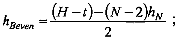


- k is a spacing bias parameter, where a value of 1 is used for relatively equal spacing between the reinforcement layers whereas a value of 0 gives a minimum spacing of the outer reinforcement layers.
- For an odd number of reinforcement layers 130, 140, 170, 180 and 190 as shown in
Fig. 3 , the area moment of inertia Im will be expressed as INodd, and the following equation provides for the calculation of INodd:
where

- Calculated as shown above, the three structural section properties Geff*A, Emembrane*Im,, and Emembrane*Am can be used to reconstruct
shear band 110 as needed while still meeting (or improving upon) the target performance characteristics ofreference tire 100 set forth in Table 1. For the example introduced above, it is desired to reduce the overall thickness H of thereference shear band 110 by 3 mm while still meeting or improving upon the performance characteristics of Table 1. However, other changes to shearband 110 can also be accomplished using the methods of the present invention as well. For example, the original value of theshear band 110 thickness (HREF) could be targeted for reduction by as much as 50 percent. In fact, any value for the desiredthickness shear band 110 may be targeted (HTARGET), provided such value is at least four times the thickness of a reinforcement layer (t). Alternatively, the methods of the present invention also allow for the original value of the shear band thickness HREF to remain constant while the values for Secant Vertical Stiffness and Tangent Vertical Stiffness are increased or µp/p is decreased. Regardless, as part of an exemplary method of the present invention, a value for HTARGET is specified for the new construction ofshear band 110, where HTARGET may be the same or smaller than HREF. - Using the selected target value for thickness HTARGET, the structural section property Geff*A is then calculated for a shear band having at least one additional reinforcement layer as compared to the
reference shear band 110. For example,reference shear band 110 is shown as having tworeinforcement layers - The new (Geff*A)CALC as determined using three reinforcement layers (N=3) is then compared to (Geff*A)REF for the
reference shear band 110. If the newly calculated (Geff*A)CALC is less than the reference value of (Geff*A)REF forreference shear band 110, then the number of reinforcement layers is again increased by one (N=4) and the value for (Geff*A)CALC is again recalculated. This process is repeated until the new value for (Geff*A)CALC is greater than or about equal to the original value of (Geff*A)REF for thereference shear band 110 with only tworeinforcement layers - The process of increasing the number of reinforcement layers N until the new value (Geff*A)CALC is more than the reference value for (Geff*A)REF can be repeated until the following limit is reached:

- Upon adding an additional reinforcement layer that provides a (Geff*A)CALC close to or above the reference value of (Geff*A)REF, the values for Emembrane*Am are Emembrane*Im at the new number of reinforcement layers can also be calculated. The new value for Emembrane*Am will always exceed the reference values of Emembrane*Am because this structural section property is directly affected by the number of reinforcement layers and because at least one reinforcement layer has been added to the
original shear band 110 at this point in the process. However, the computed value for Emembrane*Im may not meet or exceed the reference value for Emembrane*Im. - Using HTARGET and NTOTAL (the number of reinforcement layers at which (Geff*A)CALC exceeded the reference (Geff*A)REF), the values of the four performance characteristics - i.e., the Tangent Vertical Stiffness, Secant Vertical Stiffness, Contact Pressure, and µp/p - are determined using e.g., finite element analysis and a model of the tire with the shear band now having NTOTAL reinforcement layers. The new values for the Tangent Vertical Stiffness, Secant Vertical Stiffness, Contact Pressure and µp/p are then compared to the original reference values (e.g., the values in Table 1). If the new values meet or exceed the original reference values, then the process can be stopped as the design goal has been reached.
- If, however, the new values for Tangent Vertical Stiffness or Secant Vertical Stiffness are lower than the reference values for Tangent and Secant Vertical Stiffness, then Emembrane*Im must be increased. Alternatively, even if the new values for Tangent Vertical Stiffness, Secant Vertical Stiffness, Contact Pressure are acceptable, the new value for µp/p may be unacceptable or further reduction may be desired and, therefore, Emembrane*Im must be increased. To increase Bmembrane*Im, the value for spacing bias parameter k set forth with equations (7) and (8) above must be decreased incrementally. As the bias parameter k is decreased, the reinforcement layers added to the shear band that are not located on the neutral fiber will be pushed out toward the outermost and innermost reinforcement layers 130 and 140 and this will cause Emembrane*Im to increase without impacting the value of thickness HTARGET, (Geff*A)CALC, or (Emembrane*Am)CALC.
- Accordingly, for each new value of parameter k selected, another model of the tire with the shear band construction using the new value for parameter k is constructed and e.g., finite element analysis is used to compute the four performance characteristics - i.e., the Tangent Vertical Stiffness, Secant Vertical Stiffness, Contact Pressure, and µp/p. These new values are again compared to the reference values. If the Vertical Stiffness (Tangent, Secant, or both) are less than the values of Vertical Stiffness for the reference shear band, then the process of decreasing parameter k is continued until the new values exceed or are about equal to the reference values for Vertical Stiffness. Even if the new Vertical Stiffness values are acceptable, the process of decreasing parameter k can also be repeated if the value for µp/p is unacceptable - i.e., too large or higher than the value of µp/p for the
reference shear band 110. - If parameter k reaches zero before the new values of Tangent Vertical Stiffness, Secant Vertical Stiffness, and µp/p reach acceptable or target values, then the value of HTARGET must be increased and the process must be repeated again starting with one more reinforcement layer than the
reference shear band 110 i.e., NREF + 1. More specifically, forshear band 110 having NREF = 2, the value of HTARGET is increased and a new value for (Geff*A)CALC is calculated restarting with a value of N=3 reinforcement layers. This (Geff*A)CALC is then compared to (Geff*A)REF, and if (Geff*A)CALC is not greater than or about equal to (Geff*A)REF, the process is then repeated by increasing the number of reinforcement layers N again as previously described. - The method described above was applied to the
reference shear band 110 having only tworeinforcement layers TABLE 3 Inputs H N k t W Emembrane Gm Gsl Geff Geff*A Im Emembrane*Im A Emembrane*A 18 2 1 1.00 230 2000 100 0.400 .45 1.862 33,273 66,546,667 460 920,000 15 2 1 1.00 230 2000 100 0.400 .46 1,591 22,578 45,156,667 460 920,000 15 3 1 1.00 230 2000 100 0.400 .50 1,723 22,598 45,195,000 690 1,380,000 15 4 1 1.00 230 2000 100 0.400 .54 1,879 25,121 50,242,222 920 1,840,000 Note: Units are mm and daN - The first row of data indicates the
reference shear band 110 having a shear layer thickness HREF of 18 mm, a width W of 230 mm, and two (N=2) reinforcement layers. The three rows that follow are performed with the target thickness of HTARGET of 15 mm with the goal of reducing the thickness of theshear band 110 while maintaining or improving certain performance characteristics such as vertical stiffness and µp/p. Although it is perhaps not possible to match the performance characteristics exactly, as shown in Table 3, a (Geff*A)CALC that exceeded the value (Geff*A)REF for thereference shear band 110 is obtained when four reinforcement layers (N=4) are used. It is again noted that the above-described method assumes that the construction oftire 100 otherwise remains the same - i.e., the same materials (e.g., elastomers) are used for theshear layer 120, the same number ofweb spokes 150 are used, the same hub is used, etc. - Using the value of four reinforcement layers (NTOTAL=4),
tire 100 was modeled again and, using finite element analysis, the four performance characteristics used in Table 1 (Tangent Vertical Stiffness, Secant Vertical Stiffness, Contact Pressure, and µp/p) were recalculated. The results are set forth in Table 4.TABLE 4 Vertical Stiffness (Tangent) Vertical Stiffness (Secant) Contact Pressure µp/p 32.5 daN/mm 40.3 daN/mm 2.31 bar .046 mm - A comparison of Table 4 and Table 1 shows that the thickness of the
shear band 110 can be reduced by 3 mm while maintaining its vertical stiffness characteristics. However, Table 4 also provides an unexpected result in that µp/p has actually decreased by reducing the thickness H ofshear band 110 and doubling the number of reinforcement layers. More specifically, the targeted modification ofshear band 110 will not only allow for an increase in thetread portion 105 by 3 mm but will also result in less radial displacement of theshear band 110 and, therefore, smoother operation oftire 100. - It should be understood that
shear layer 120 maybe constructed from any material that provides the desired mechanical properties described herein. While elastomeric materials may be used, the present invention is not limited to such. For example, materials that may be used forshear layer 120 include those previously described (natural and synthetic rubbers, polyurethanes, foamed rubbers and polyurethanes, segmented copolyesters, and block co-polymers of nylon) as well non-elastomeric materials such as, for example, fiber-reinforced composites or meta-materials. - While the present subject matter has been described in detail with respect to specific exemplary embodiments and methods thereof, it will be appreciated that those skilled in the art, upon attaining an understanding of the foregoing may readily produce alterations to, variations of, and equivalents to such embodiments. Accordingly, the scope of the present disclosure is by way of example rather than by way of limitation, and the subject disclosure does not preclude inclusion of such modifications, variations and/or additions to the present subject matter as would be readily apparent to one of ordinary skill in the art using the teachings disclosed herein without departing from the scope of the appended claims.
Claims (13)
- A method for modifying a shear band having (110) a thickness of HREF and a total number of reinforcement layers of NREF, the method comprising the steps of:determining the vertical stiffness of the shear band and (Geff*A)REF using a thickness for the shear band of HREF and a total of NREF reinforcement layers (130, 140) for the shear band (110), where (Geff*A)REF is the product of the effective shear modulus Geff and the total cross-sectional area A of the shear band;selecting a target value HTARGET as the target thickness for the shear band (110);increasing by 1 the total number of reinforcement layers (130, 140) in the shear band (110);calculating (Geff*A)CALC, where (Geff*A)CALC is the product of the effective shear modulus Geff and the total cross-sectional area A using a thickness of HTARGET for the shear band (110) and using the total number of reinforcement layers (130, 140) provided by said increasing step for the shear band (110);comparing (Geff*A)CALC from said calculating step with (Geff*A)REF from said determining step and, if (Geff*A)CALC is less than (Geff*A)REF, then repeating said increasing step and said calculating step until (Geff*A)CALC is greater than or about equal to (Geff*A)REF and the total number of reinforcement layers (130, 140) becomes NTOTAL, where NTOTAL is the total number of reinforcement layers at which (Geff*A)CALC becomes greater than or about equal to the (Geff*A)REF;computing the vertical stiffness using a thickness of HTARGET for the shear band (110) and the number of reinforcement layers NTOTAL for the shear band as provided by said comparing step; andreferring to the vertical stiffness from said computing step and the vertical stiffness from said determining step and, if the vertical stiffness from said computing step is less than the vertical stiffness from said determining step, thenmoving at least one of the reinforcement layers (130, 140) between an outermost reinforcement layer and an innermost reinforcement layer to a new position in the shear band (110) that is closer to either the outermost reinforcement layer or the innermost reinforcement layer, and repeating said computing and referring steps until the vertical stiffness from said computing step is greater than or about equal to the vertical stiffness from said determining step.
- A method for modifying a shear band having a thickness of HREF and a total number of reinforcement layers of NREF as in claim 1, further comprising the step of increasing the target thickness HTARGET of the shear band (110) if the distance between any adjacent reinforcement layers (130, 140) in the shear band (110) becomes less than one-half the thickness of a single reinforcement layer.
- A method for modifying a shear band having a thickness of HREF and a total number of reinforcement layers of NREF as in claim 2, further comprising repeating said steps of increasing, calculating, comparing, computing and referring beginning with a total of NREF reinforcement layers (130, 140) in the shear band (110).
- A method for modifying a shear band having a thickness of HREF and a total number of reinforcement layers of NREF as in claim 1, further comprising the step of increasing the target thickness HTARGET of the shear band (110) if said step of comparing does not provide a (Geff*A)CALC that is greater than or about equal to (Geff*A)REF.
- A method for modifying a shear band having a thickness of HREF and a total number of reinforcement layers of NREF as in claim 4, further comprising repeating said increasing, calculating, comparing, computing and referring steps beginning with a total of NREF reinforcement layers (130, 140) in the shear band (110).
- A method for modifying a shear band having a thickness of HREF and a total number of reinforcement layers of NREF as in claim 1, further comprising the step of increasing the target thickness of the shear band HTARGET.
- A method for modifying a shear band (110) having a thickness of HREF and a total number of reinforcement layers of NREF as in claim 1, further comprising the steps of:calculating the value of µp/p REF using a thickness of HREF for the shear band (110) and a total of NREF reinforcement layers (130, 140) for the shear band (110);calculating the value of µp/p TARGET using a thickness of HTARGET for the shear band (110) and using the number of reinforcement layers NTOTAL for the shear band (110) provided by said comparing step; andcomparing the value of µp/p TARGET to µp/p REF and, if µp/p TARGET is not less than or about equal to µp/p REF, then moving at least one of the reinforcement layers (130, 140) between an outermost reinforcement layer and an innermost reinforcement layer to a new position in the shear band (110) that is closer to either the outermost reinforcement layer or the innermost reinforcement layer.
- A method for modifying a shear band having a thickness of HREF and a total number of reinforcement layers of NREF as in claim 1, further comprising the step of manufacturing a shear band (110) having a thickness of HTARGET as used in said selecting step and having the number of reinforcement layers NTOTAL provided by said comparing step.
- A method for modifying a shear band having a thickness of HREF and a total number of reinforcement layers of NREF as in claim 1, further comprising increasing the thickness t of the reinforcement layers (130, 140) if said comparing step does not result in a (Geff*A)CALC that is greater than or about equal to (Geff*A)REF.
- A method for modifying a shear band having a thickness of HREF and a total number of reinforcement layers of NREF as in claim 9, further comprising repeating said steps of increasing, calculating, comparing, computing and referring beginning with a total of NREF reinforcement layers (130, 140) in the shear band (110).
- A method for modifying a shear band having a thickness of HREF and a total number of reinforcement layers of NREF as in claim 1, further comprising the step of increasing the circumferential shear modulus Gm of the reinforcement layers (130, 140) if said comparing step does not result in a (Geff*A)CALC that is greater than or about equal to (Geff*A)REF.
- A method for modifying a shear band having a thickness of HREF and a total number of reinforcement layers of NREF as in claim 1, further comprising the step of increasing the circumferential modulus Emembrane of the reinforcement layers (130, 140) if said comparing step does not result in a vertical stiffness that is greater than or equal to the vertical stiffness from said determining step.
- A method for modifying a shear band having a thickness of HREF and a total number of reinforcement layers of NREF as in claim 1, further comprising the step of increasing the circumferential modulus Emembrane of the reinforcement layers (130, 140) if said comparing step does not result in a value of µp/p that is greater than the value of µp/p using a thickness of HREF for the shear band (110) and using the number of reinforcement layers NREF for the shear band (110).
Priority Applications (1)
| Application Number | Priority Date | Filing Date | Title |
|---|---|---|---|
| EP15163101.7A EP2910388B1 (en) | 2009-10-15 | 2009-10-15 | Apparatus for multilayer shear band reinforcement |
Applications Claiming Priority (1)
| Application Number | Priority Date | Filing Date | Title |
|---|---|---|---|
| PCT/US2009/060746 WO2011046553A1 (en) | 2009-10-15 | 2009-10-15 | Method and apparatus for multilayer shear band reinforcement |
Related Child Applications (2)
| Application Number | Title | Priority Date | Filing Date |
|---|---|---|---|
| EP15163101.7A Division EP2910388B1 (en) | 2009-10-15 | 2009-10-15 | Apparatus for multilayer shear band reinforcement |
| EP15163101.7A Division-Into EP2910388B1 (en) | 2009-10-15 | 2009-10-15 | Apparatus for multilayer shear band reinforcement |
Publications (3)
| Publication Number | Publication Date |
|---|---|
| EP2488355A1 EP2488355A1 (en) | 2012-08-22 |
| EP2488355A4 EP2488355A4 (en) | 2013-06-26 |
| EP2488355B1 true EP2488355B1 (en) | 2015-12-16 |
Family
ID=43876388
Family Applications (2)
| Application Number | Title | Priority Date | Filing Date |
|---|---|---|---|
| EP09850468.1A Not-in-force EP2488355B1 (en) | 2009-10-15 | 2009-10-15 | Method for multilayer shear band reinforcement |
| EP15163101.7A Active EP2910388B1 (en) | 2009-10-15 | 2009-10-15 | Apparatus for multilayer shear band reinforcement |
Family Applications After (1)
| Application Number | Title | Priority Date | Filing Date |
|---|---|---|---|
| EP15163101.7A Active EP2910388B1 (en) | 2009-10-15 | 2009-10-15 | Apparatus for multilayer shear band reinforcement |
Country Status (11)
| Country | Link |
|---|---|
| US (2) | US8960248B2 (en) |
| EP (2) | EP2488355B1 (en) |
| JP (1) | JP5628329B2 (en) |
| KR (2) | KR101493303B1 (en) |
| CN (1) | CN102574347B (en) |
| BR (1) | BR112012008836B1 (en) |
| CA (1) | CA2774927C (en) |
| MX (1) | MX2012004176A (en) |
| RU (1) | RU2497677C1 (en) |
| WO (1) | WO2011046553A1 (en) |
| ZA (1) | ZA201202051B (en) |
Families Citing this family (35)
| Publication number | Priority date | Publication date | Assignee | Title |
|---|---|---|---|---|
| US8813797B2 (en) * | 2011-01-30 | 2014-08-26 | Compagnie Generale Des Etablissements Michelin | Controlled buckling of a shear band for a tire |
| RU2014130090A (en) * | 2011-12-22 | 2016-02-10 | Мишлен Решерш Э Текник, С.А. | ALTERNATED REINFORCED SHEAR STRIP |
| US9266388B2 (en) * | 2012-09-27 | 2016-02-23 | Mtd Products Inc | Non-pneumatic tire |
| US9242509B2 (en) * | 2013-02-07 | 2016-01-26 | Alice Chang | Non pneumatic vehicle tires and pneumatic vehicle tires with tread patterns |
| KR101356326B1 (en) | 2013-02-28 | 2014-01-29 | 한국타이어 주식회사 | Non-pneumatic tire having reinforcing material of plate wire structure |
| JP6159138B2 (en) * | 2013-05-07 | 2017-07-05 | 住友ゴム工業株式会社 | Airless tire |
| EP3007909A4 (en) | 2013-06-15 | 2017-03-01 | Ronald Thompson | Annular ring and non-pneumatic tire |
| BR112016006422A2 (en) | 2013-09-24 | 2017-08-01 | Bridgestone Americas Tire Operations Llc | tire with toroidal element |
| JP6178700B2 (en) * | 2013-11-11 | 2017-08-09 | 住友ゴム工業株式会社 | Tread ring stiffness measuring apparatus and tread ring uniformity measuring method |
| EP3086948B1 (en) | 2013-12-24 | 2020-03-11 | Bridgestone Americas Tire Operations, LLC | Airless tire construction having variable stiffness |
| WO2016089480A1 (en) | 2014-12-03 | 2016-06-09 | Bridgestone Americas Tire Operations, Llc | Non-pneumatic tire |
| JP6727136B2 (en) | 2015-01-15 | 2020-07-22 | 株式会社ブリヂストン | Non-pneumatic tire |
| CA2976055A1 (en) | 2015-02-04 | 2016-08-11 | Advancing Mobility, Llc. | Non-pneumatic tire and other annular devices |
| USD770539S1 (en) * | 2015-06-16 | 2016-11-01 | Michelin Recherche Et Technique S.A. | Tire |
| EP3390074A4 (en) * | 2015-12-16 | 2019-06-26 | Ronald H. Thompson | Wheel comprising a non-pneumatic tire |
| WO2017111944A1 (en) | 2015-12-22 | 2017-06-29 | Compagnie Generale Des Etablissements Michelin | Reinforcement structure for non-pneumatic wheel |
| WO2017116386A1 (en) * | 2015-12-28 | 2017-07-06 | Compagnie Generale Des Etablissements Michelin | Method of forming non-pneumatic tire using intermediate section |
| FR3056442A1 (en) | 2016-09-27 | 2018-03-30 | Compagnie Generale Des Etablissements Michelin | LAMINATE PRODUCT BASED ON SILICONE RUBBER AND FIBER-RESIN COMPOSITE |
| FR3056444A1 (en) * | 2016-09-27 | 2018-03-30 | Compagnie Generale Des Etablissements Michelin | NON-PNEUMATIC ELASTIC WHEEL INCORPORATING LAMINATE BASED ON SILICONE RUBBER AND FIBER-RESIN COMPOSITE |
| EP3519204B1 (en) | 2016-10-03 | 2020-07-29 | Compagnie Générale des Etablissements Michelin | Reinforced rubber spoke for a tire |
| JP2018083458A (en) * | 2016-11-21 | 2018-05-31 | 株式会社ブリヂストン | Pneumatic tire and two wheel vehicle |
| US10639934B2 (en) | 2016-11-22 | 2020-05-05 | The Goodyear Tire & Rubber Company | Shear band for a structurally supported tire |
| WO2018125197A1 (en) | 2016-12-30 | 2018-07-05 | Compagnie Generale Des Etablissements Michelin | Resilient composite structural support |
| WO2018125195A1 (en) * | 2016-12-30 | 2018-07-05 | Compagnie Generale Des Etablissements Michelin | Fixture for spoke to shear band attachment for a non-pneumatic tire with spoke pre-compression |
| US11179969B2 (en) | 2017-06-15 | 2021-11-23 | Camso Inc. | Wheel comprising a non-pneumatic tire |
| WO2019050549A1 (en) * | 2017-09-11 | 2019-03-14 | Compagnie Generale Des Etablissements Michelin | Non-pneumatic tire |
| JP2019107846A (en) * | 2017-12-20 | 2019-07-04 | Toyo Tire株式会社 | Method for manufacturing tire constituting member |
| US11577549B2 (en) * | 2017-12-21 | 2023-02-14 | Compagnie Generale Des Establissements Michelin | Reinforced resilient support for a non-pneumatic tire |
| US11027578B2 (en) | 2018-02-26 | 2021-06-08 | The Goodyear Tire & Rubber Company | Wheel and tire assembly |
| CN108446485B (en) * | 2018-03-16 | 2021-05-11 | 河海大学 | Strip drawing reinforcement evaluation method |
| CN113226799A (en) | 2019-01-04 | 2021-08-06 | 普利司通美国轮胎运营有限责任公司 | Tire tread with belt layer |
| WO2020142670A1 (en) | 2019-01-04 | 2020-07-09 | Bridgestone Americas Tire Operations, Llc | Tire tread band with shim layers |
| US20210170795A1 (en) * | 2019-12-10 | 2021-06-10 | The Goodyear Tire & Rubber Company | Shear band |
| WO2021222833A1 (en) * | 2020-04-30 | 2021-11-04 | DUTY, John | Non-pneumatic tire |
| CN112373243B (en) * | 2020-10-20 | 2021-08-06 | 南京航空航天大学 | Non-inflatable wheel capable of protecting rim and improving vehicle driving comfort |
Family Cites Families (52)
| Publication number | Priority date | Publication date | Assignee | Title |
|---|---|---|---|---|
| US1495083A (en) | 1921-02-01 | 1924-05-20 | L A Clark | Cushion tire |
| US1440974A (en) | 1922-01-27 | 1923-01-02 | William H Dornburgh | Tire |
| US2388421A (en) | 1942-06-23 | 1945-11-06 | Gen Tire & Rubber Co | Pneumatic tire |
| GB1257017A (en) | 1968-02-06 | 1971-12-15 | ||
| US3779835A (en) | 1971-06-03 | 1973-12-18 | Akron Standard Division Of Eag | Building drum |
| CA1046914A (en) | 1974-03-14 | 1979-01-23 | Claude H. Allard | Tire cord fabrics for belts of belted pneumatic tires |
| US3973613A (en) | 1974-12-12 | 1976-08-10 | Owens-Corning Fiberglas Corporation | Tire reinforcement |
| US4024895A (en) | 1976-03-24 | 1977-05-24 | E. I. Du Pont De Nemours And Company | Product reinforcing fabric and two-component weft yarn useful therein |
| CA1215242A (en) | 1981-08-31 | 1986-12-16 | Dhiraj H. Darjee | Stitch-bonded fabrics for reinforcing coated abrasive backings |
| US4734144A (en) | 1985-04-25 | 1988-03-29 | Grumman Aerospace Corporation | Banded-tire building method |
| US4794966A (en) | 1987-04-21 | 1989-01-03 | Grumman Aerospace Corporation | Run-flat tire incorporating band segment and coil members |
| US4966212A (en) | 1988-08-05 | 1990-10-30 | Giles Hill | Wheel and solid rubber tire assembly and method |
| AU625337B2 (en) | 1989-05-31 | 1992-07-09 | Sp Reifenwerke Gmbh | Vehicle tyre |
| FR2652310A1 (en) * | 1989-09-28 | 1991-03-29 | Michelin & Cie | NON-PNEUMATIC DEFORMABLE BANDAGE. |
| US5221382A (en) | 1991-05-10 | 1993-06-22 | The Goodyear Tire & Rubber Company | Pneumatic tire including gas absorbing cords |
| US5265659A (en) | 1992-03-18 | 1993-11-30 | Uniroyal Goodrich Licensing Services, Inc. | Non-pneumatic tire with ride-enhancing insert |
| US5313994A (en) * | 1992-05-15 | 1994-05-24 | Southeast Tire Company | Solid rubber wheel and tire assembly with angled cross bars |
| US5333568A (en) | 1992-11-17 | 1994-08-02 | America3 Foundation | Material for the fabrication of sails |
| US5565257A (en) * | 1993-03-24 | 1996-10-15 | Tingley; Daniel A. | Method of manufacturing wood structural member with synthetic fiber reinforcement |
| AU717784B2 (en) * | 1995-07-24 | 2000-03-30 | Jalcos Holdings Inc. | Filled pneumatic tires and methods of manufacturing thereof |
| US5837077A (en) | 1995-08-18 | 1998-11-17 | The Yokohama Rubber, Co., Ltd. | Pneumatic vehicle tire having belt wound from flattened tubular tape |
| US6109319A (en) | 1995-08-24 | 2000-08-29 | Gardetto; William W. | Run-flat support for pneumatic tired wheel |
| US5906836A (en) | 1995-11-27 | 1999-05-25 | American Mobility Limited Partnership | Spin casting apparatus for manufacturing an item from polyurethane foam |
| US5879484A (en) | 1997-01-13 | 1999-03-09 | Bridgestone/Firestone, Inc. | Run flat banded pneumatic tire |
| US6267165B1 (en) | 1998-06-19 | 2001-07-31 | The Goodyear Tire & Rubber Company | Pneumatic tire with specified aramid belt |
| US6148885A (en) | 1998-07-21 | 2000-11-21 | Bridgestone/Firestone Research, Inc. | Pneumatic tire with band element |
| US6701987B1 (en) | 1999-04-12 | 2004-03-09 | The Goodyear Tire & Rubber Company | Tread stiffening support ribs for runflat tire |
| US6182728B1 (en) * | 1999-06-04 | 2001-02-06 | Hankook Tire | Pneumatic run flat tire |
| US7650919B2 (en) | 1999-12-10 | 2010-01-26 | Michelin Recherche of Technique S.A. | Non-pneumatic tire having web spokes |
| DE69929903T2 (en) | 1999-12-10 | 2006-09-28 | Michelin Recherche Et Technique S.A. | ELASTIC SELF-WEARING TIRES |
| US7418988B2 (en) * | 1999-12-10 | 2008-09-02 | Michelin Recherche Et Technique S.A. | Non-pneumatic tire |
| US6460586B1 (en) * | 2000-03-29 | 2002-10-08 | Bridgestone/Firestone North American Tire, Llc | Multi-region band element for run flat tire |
| US6470937B1 (en) | 2000-10-03 | 2002-10-29 | Bridgestone/Firestone North American Tire, Llc | Run flat pneumatic tire and anticlastic band element therefor |
| US6439288B1 (en) | 2000-11-28 | 2002-08-27 | Bridgestone/Firestone North American Tire, Llc | Pneumatic tire with variable thickness band element |
| US7013939B2 (en) * | 2001-08-24 | 2006-03-21 | Michelin Recherche Et Technique S.A. | Compliant wheel |
| RU2269425C2 (en) * | 2001-08-24 | 2006-02-10 | Сосьете Де Текнолоджи Мишлен | Non-pneumatic tire |
| KR100810935B1 (en) | 2001-08-24 | 2008-03-10 | 소시에떼 드 테크놀로지 미쉐린 | Non-pneumatic tire |
| US6994134B2 (en) | 2001-10-05 | 2006-02-07 | Michelin Recherche Et Technique S.A. | Structurally supported resilient tire and materials |
| US6622764B2 (en) | 2002-02-01 | 2003-09-23 | The Goodyear Tire & Rubber Company | Underlay structure for increased crown stiffening |
| US7174934B2 (en) * | 2003-08-07 | 2007-02-13 | Giles A. Hill, III | Solid rubber tire including relatively hard rubber layer and relatively soft rubber layer |
| US7125083B2 (en) | 2004-06-04 | 2006-10-24 | Nhs, Inc. | Wheel with dual density |
| EP1637863A1 (en) | 2004-09-20 | 2006-03-22 | PIRELLI PNEUMATICI S.p.A. | Method for calculating a friction-slippage curve for a tire |
| US7363805B2 (en) * | 2005-09-30 | 2008-04-29 | Ford Motor Company | System for virtual prediction of road loads |
| EP2021192B1 (en) * | 2006-10-13 | 2012-06-13 | Société de Technologie Michelin | Improved shear band |
| JP3923073B1 (en) | 2006-10-27 | 2007-05-30 | 横浜ゴム株式会社 | Non-pneumatic tire |
| WO2008102048A1 (en) | 2007-02-21 | 2008-08-28 | Nokian Renkaat Oyj | Improved belt structure in automobile tires |
| US8109308B2 (en) * | 2007-03-27 | 2012-02-07 | Resilient Technologies LLC. | Tension-based non-pneumatic tire |
| FR2916159B1 (en) | 2007-05-14 | 2011-03-18 | Michelin Soc Tech | PNEUMATIC FOR HEAVY VEHICLES |
| WO2009005946A1 (en) | 2007-06-29 | 2009-01-08 | Societe De Technologie Michelin | Elastic shear band with columnar elements |
| US20090071584A1 (en) | 2007-09-19 | 2009-03-19 | Ping Zhang | Tire having tread with an internal closed cellular rubber transition layer |
| US8544515B2 (en) * | 2008-11-10 | 2013-10-01 | Mkp Structural Design Associates, Inc. | Ultralightweight runflat tires based upon negative poisson ratio (NPR) auxetic structures |
| US20110223366A1 (en) | 2010-03-12 | 2011-09-15 | Petri Patrick A | Reinforced continuous loop matrix member; continuous loop reinforcement assembly; flexible cylindrical reinforcement band; and axially reinforced cylindrical coil |
-
2009
- 2009-10-15 EP EP09850468.1A patent/EP2488355B1/en not_active Not-in-force
- 2009-10-15 BR BR112012008836-0A patent/BR112012008836B1/en not_active IP Right Cessation
- 2009-10-15 RU RU2012119754/04A patent/RU2497677C1/en not_active IP Right Cessation
- 2009-10-15 KR KR1020127008931A patent/KR101493303B1/en active IP Right Grant
- 2009-10-15 WO PCT/US2009/060746 patent/WO2011046553A1/en active Application Filing
- 2009-10-15 EP EP15163101.7A patent/EP2910388B1/en active Active
- 2009-10-15 KR KR1020147027075A patent/KR20140133886A/en active Search and Examination
- 2009-10-15 MX MX2012004176A patent/MX2012004176A/en active IP Right Grant
- 2009-10-15 JP JP2012534149A patent/JP5628329B2/en not_active Expired - Fee Related
- 2009-10-15 CA CA2774927A patent/CA2774927C/en not_active Expired - Fee Related
- 2009-10-15 CN CN200980161895.4A patent/CN102574347B/en active Active
- 2009-10-15 US US13/497,618 patent/US8960248B2/en active Active
-
2012
- 2012-03-20 ZA ZA2012/02051A patent/ZA201202051B/en unknown
-
2015
- 2015-01-14 US US14/596,306 patent/US9493045B2/en active Active
Also Published As
| Publication number | Publication date |
|---|---|
| US8960248B2 (en) | 2015-02-24 |
| ZA201202051B (en) | 2013-01-30 |
| JP5628329B2 (en) | 2014-11-19 |
| US20120216932A1 (en) | 2012-08-30 |
| BR112012008836A2 (en) | 2016-08-09 |
| US9493045B2 (en) | 2016-11-15 |
| BR112012008836A8 (en) | 2017-12-05 |
| EP2488355A1 (en) | 2012-08-22 |
| CN102574347B (en) | 2016-01-20 |
| WO2011046553A1 (en) | 2011-04-21 |
| EP2910388A1 (en) | 2015-08-26 |
| KR20140133886A (en) | 2014-11-20 |
| CA2774927A1 (en) | 2011-04-21 |
| CN102574347A (en) | 2012-07-11 |
| CA2774927C (en) | 2015-03-24 |
| MX2012004176A (en) | 2012-06-28 |
| KR20120049400A (en) | 2012-05-16 |
| US20150122385A1 (en) | 2015-05-07 |
| KR101493303B1 (en) | 2015-02-13 |
| EP2488355A4 (en) | 2013-06-26 |
| JP2013507296A (en) | 2013-03-04 |
| EP2910388B1 (en) | 2018-09-19 |
| BR112012008836B1 (en) | 2019-01-22 |
| RU2497677C1 (en) | 2013-11-10 |
Similar Documents
| Publication | Publication Date | Title |
|---|---|---|
| EP2488355B1 (en) | Method for multilayer shear band reinforcement | |
| US11400672B2 (en) | Annular ring and non-pneumatic tire | |
| EP2021192B1 (en) | Improved shear band | |
| EP2367697B1 (en) | Improved hydroplaning performance for a tire | |
| US8662122B2 (en) | System for non-pneumatic support of a vehicle | |
| CA2525982C (en) | Non-pneumatic tire | |
| JP2013507296A5 (en) | ||
| US20120048440A1 (en) | Composite material | |
| CN106985601A (en) | Non-inflatable tyre | |
| CN113226798A (en) | Vehicle tyre comprising a reinforcing structure | |
| JP5833185B2 (en) | Method and apparatus for strengthening multilayer shear bands | |
| RU2269425C2 (en) | Non-pneumatic tire |
Legal Events
| Date | Code | Title | Description |
|---|---|---|---|
| PUAI | Public reference made under article 153(3) epc to a published international application that has entered the european phase |
Free format text: ORIGINAL CODE: 0009012 |
|
| 17P | Request for examination filed |
Effective date: 20120322 |
|
| AK | Designated contracting states |
Kind code of ref document: A1 Designated state(s): AT BE BG CH CY CZ DE DK EE ES FI FR GB GR HR HU IE IS IT LI LT LU LV MC MK MT NL NO PL PT RO SE SI SK SM TR |
|
| RAP1 | Party data changed (applicant data changed or rights of an application transferred) |
Owner name: COMPAGNIE GENERALE DES ETABLISSEMENTS MICHELIN Owner name: MICHELIN RECHERCHE ET TECHNIQUE S.A. |
|
| DAX | Request for extension of the european patent (deleted) | ||
| A4 | Supplementary search report drawn up and despatched |
Effective date: 20130528 |
|
| RIC1 | Information provided on ipc code assigned before grant |
Ipc: B29D 30/02 20060101AFI20130522BHEP Ipc: B60C 7/18 20060101ALI20130522BHEP Ipc: B60C 9/18 20060101ALI20130522BHEP |
|
| 17Q | First examination report despatched |
Effective date: 20140225 |
|
| GRAP | Despatch of communication of intention to grant a patent |
Free format text: ORIGINAL CODE: EPIDOSNIGR1 |
|
| INTG | Intention to grant announced |
Effective date: 20150609 |
|
| GRAS | Grant fee paid |
Free format text: ORIGINAL CODE: EPIDOSNIGR3 |
|
| GRAA | (expected) grant |
Free format text: ORIGINAL CODE: 0009210 |
|
| AK | Designated contracting states |
Kind code of ref document: B1 Designated state(s): AT BE BG CH CY CZ DE DK EE ES FI FR GB GR HR HU IE IS IT LI LT LU LV MC MK MT NL NO PL PT RO SE SI SK SM TR |
|
| REG | Reference to a national code |
Ref country code: GB Ref legal event code: FG4D |
|
| REG | Reference to a national code |
Ref country code: CH Ref legal event code: EP |
|
| REG | Reference to a national code |
Ref country code: IE Ref legal event code: FG4D |
|
| REG | Reference to a national code |
Ref country code: AT Ref legal event code: REF Ref document number: 765348 Country of ref document: AT Kind code of ref document: T Effective date: 20160115 |
|
| REG | Reference to a national code |
Ref country code: DE Ref legal event code: R096 Ref document number: 602009035324 Country of ref document: DE |
|
| REG | Reference to a national code |
Ref country code: NL Ref legal event code: FP |
|
| REG | Reference to a national code |
Ref country code: LT Ref legal event code: MG4D |
|
| PG25 | Lapsed in a contracting state [announced via postgrant information from national office to epo] |
Ref country code: HR Free format text: LAPSE BECAUSE OF FAILURE TO SUBMIT A TRANSLATION OF THE DESCRIPTION OR TO PAY THE FEE WITHIN THE PRESCRIBED TIME-LIMIT Effective date: 20151216 Ref country code: LT Free format text: LAPSE BECAUSE OF FAILURE TO SUBMIT A TRANSLATION OF THE DESCRIPTION OR TO PAY THE FEE WITHIN THE PRESCRIBED TIME-LIMIT Effective date: 20151216 Ref country code: NO Free format text: LAPSE BECAUSE OF FAILURE TO SUBMIT A TRANSLATION OF THE DESCRIPTION OR TO PAY THE FEE WITHIN THE PRESCRIBED TIME-LIMIT Effective date: 20160316 |
|
| REG | Reference to a national code |
Ref country code: AT Ref legal event code: MK05 Ref document number: 765348 Country of ref document: AT Kind code of ref document: T Effective date: 20151216 |
|
| PG25 | Lapsed in a contracting state [announced via postgrant information from national office to epo] |
Ref country code: LV Free format text: LAPSE BECAUSE OF FAILURE TO SUBMIT A TRANSLATION OF THE DESCRIPTION OR TO PAY THE FEE WITHIN THE PRESCRIBED TIME-LIMIT Effective date: 20151216 Ref country code: SE Free format text: LAPSE BECAUSE OF FAILURE TO SUBMIT A TRANSLATION OF THE DESCRIPTION OR TO PAY THE FEE WITHIN THE PRESCRIBED TIME-LIMIT Effective date: 20151216 Ref country code: FI Free format text: LAPSE BECAUSE OF FAILURE TO SUBMIT A TRANSLATION OF THE DESCRIPTION OR TO PAY THE FEE WITHIN THE PRESCRIBED TIME-LIMIT Effective date: 20151216 Ref country code: GR Free format text: LAPSE BECAUSE OF FAILURE TO SUBMIT A TRANSLATION OF THE DESCRIPTION OR TO PAY THE FEE WITHIN THE PRESCRIBED TIME-LIMIT Effective date: 20160317 |
|
| PG25 | Lapsed in a contracting state [announced via postgrant information from national office to epo] |
Ref country code: IT Free format text: LAPSE BECAUSE OF FAILURE TO SUBMIT A TRANSLATION OF THE DESCRIPTION OR TO PAY THE FEE WITHIN THE PRESCRIBED TIME-LIMIT Effective date: 20151216 Ref country code: CZ Free format text: LAPSE BECAUSE OF FAILURE TO SUBMIT A TRANSLATION OF THE DESCRIPTION OR TO PAY THE FEE WITHIN THE PRESCRIBED TIME-LIMIT Effective date: 20151216 Ref country code: ES Free format text: LAPSE BECAUSE OF FAILURE TO SUBMIT A TRANSLATION OF THE DESCRIPTION OR TO PAY THE FEE WITHIN THE PRESCRIBED TIME-LIMIT Effective date: 20151216 |
|
| PG25 | Lapsed in a contracting state [announced via postgrant information from national office to epo] |
Ref country code: IS Free format text: LAPSE BECAUSE OF FAILURE TO SUBMIT A TRANSLATION OF THE DESCRIPTION OR TO PAY THE FEE WITHIN THE PRESCRIBED TIME-LIMIT Effective date: 20160416 Ref country code: RO Free format text: LAPSE BECAUSE OF FAILURE TO SUBMIT A TRANSLATION OF THE DESCRIPTION OR TO PAY THE FEE WITHIN THE PRESCRIBED TIME-LIMIT Effective date: 20151216 Ref country code: EE Free format text: LAPSE BECAUSE OF FAILURE TO SUBMIT A TRANSLATION OF THE DESCRIPTION OR TO PAY THE FEE WITHIN THE PRESCRIBED TIME-LIMIT Effective date: 20151216 Ref country code: PT Free format text: LAPSE BECAUSE OF FAILURE TO SUBMIT A TRANSLATION OF THE DESCRIPTION OR TO PAY THE FEE WITHIN THE PRESCRIBED TIME-LIMIT Effective date: 20160418 Ref country code: AT Free format text: LAPSE BECAUSE OF FAILURE TO SUBMIT A TRANSLATION OF THE DESCRIPTION OR TO PAY THE FEE WITHIN THE PRESCRIBED TIME-LIMIT Effective date: 20151216 Ref country code: SK Free format text: LAPSE BECAUSE OF FAILURE TO SUBMIT A TRANSLATION OF THE DESCRIPTION OR TO PAY THE FEE WITHIN THE PRESCRIBED TIME-LIMIT Effective date: 20151216 Ref country code: SM Free format text: LAPSE BECAUSE OF FAILURE TO SUBMIT A TRANSLATION OF THE DESCRIPTION OR TO PAY THE FEE WITHIN THE PRESCRIBED TIME-LIMIT Effective date: 20151216 |
|
| REG | Reference to a national code |
Ref country code: DE Ref legal event code: R097 Ref document number: 602009035324 Country of ref document: DE |
|
| REG | Reference to a national code |
Ref country code: FR Ref legal event code: PLFP Year of fee payment: 8 |
|
| PLBE | No opposition filed within time limit |
Free format text: ORIGINAL CODE: 0009261 |
|
| STAA | Information on the status of an ep patent application or granted ep patent |
Free format text: STATUS: NO OPPOSITION FILED WITHIN TIME LIMIT |
|
| PG25 | Lapsed in a contracting state [announced via postgrant information from national office to epo] |
Ref country code: DK Free format text: LAPSE BECAUSE OF FAILURE TO SUBMIT A TRANSLATION OF THE DESCRIPTION OR TO PAY THE FEE WITHIN THE PRESCRIBED TIME-LIMIT Effective date: 20151216 Ref country code: PL Free format text: LAPSE BECAUSE OF FAILURE TO SUBMIT A TRANSLATION OF THE DESCRIPTION OR TO PAY THE FEE WITHIN THE PRESCRIBED TIME-LIMIT Effective date: 20151216 |
|
| 26N | No opposition filed |
Effective date: 20160919 |
|
| PG25 | Lapsed in a contracting state [announced via postgrant information from national office to epo] |
Ref country code: BE Free format text: LAPSE BECAUSE OF FAILURE TO SUBMIT A TRANSLATION OF THE DESCRIPTION OR TO PAY THE FEE WITHIN THE PRESCRIBED TIME-LIMIT Effective date: 20151216 |
|
| PG25 | Lapsed in a contracting state [announced via postgrant information from national office to epo] |
Ref country code: SI Free format text: LAPSE BECAUSE OF FAILURE TO SUBMIT A TRANSLATION OF THE DESCRIPTION OR TO PAY THE FEE WITHIN THE PRESCRIBED TIME-LIMIT Effective date: 20151216 |
|
| REG | Reference to a national code |
Ref country code: CH Ref legal event code: PL |
|
| GBPC | Gb: european patent ceased through non-payment of renewal fee |
Effective date: 20161015 |
|
| REG | Reference to a national code |
Ref country code: IE Ref legal event code: MM4A |
|
| PG25 | Lapsed in a contracting state [announced via postgrant information from national office to epo] |
Ref country code: GB Free format text: LAPSE BECAUSE OF NON-PAYMENT OF DUE FEES Effective date: 20161015 Ref country code: LI Free format text: LAPSE BECAUSE OF NON-PAYMENT OF DUE FEES Effective date: 20161031 Ref country code: CH Free format text: LAPSE BECAUSE OF NON-PAYMENT OF DUE FEES Effective date: 20161031 |
|
| PG25 | Lapsed in a contracting state [announced via postgrant information from national office to epo] |
Ref country code: LU Free format text: LAPSE BECAUSE OF NON-PAYMENT OF DUE FEES Effective date: 20161015 |
|
| REG | Reference to a national code |
Ref country code: FR Ref legal event code: PLFP Year of fee payment: 9 |
|
| PG25 | Lapsed in a contracting state [announced via postgrant information from national office to epo] |
Ref country code: IE Free format text: LAPSE BECAUSE OF NON-PAYMENT OF DUE FEES Effective date: 20161015 |
|
| PG25 | Lapsed in a contracting state [announced via postgrant information from national office to epo] |
Ref country code: CY Free format text: LAPSE BECAUSE OF FAILURE TO SUBMIT A TRANSLATION OF THE DESCRIPTION OR TO PAY THE FEE WITHIN THE PRESCRIBED TIME-LIMIT Effective date: 20151216 Ref country code: HU Free format text: LAPSE BECAUSE OF FAILURE TO SUBMIT A TRANSLATION OF THE DESCRIPTION OR TO PAY THE FEE WITHIN THE PRESCRIBED TIME-LIMIT; INVALID AB INITIO Effective date: 20091015 |
|
| PG25 | Lapsed in a contracting state [announced via postgrant information from national office to epo] |
Ref country code: MC Free format text: LAPSE BECAUSE OF FAILURE TO SUBMIT A TRANSLATION OF THE DESCRIPTION OR TO PAY THE FEE WITHIN THE PRESCRIBED TIME-LIMIT Effective date: 20151216 Ref country code: MK Free format text: LAPSE BECAUSE OF FAILURE TO SUBMIT A TRANSLATION OF THE DESCRIPTION OR TO PAY THE FEE WITHIN THE PRESCRIBED TIME-LIMIT Effective date: 20151216 Ref country code: TR Free format text: LAPSE BECAUSE OF FAILURE TO SUBMIT A TRANSLATION OF THE DESCRIPTION OR TO PAY THE FEE WITHIN THE PRESCRIBED TIME-LIMIT Effective date: 20151216 Ref country code: MT Free format text: LAPSE BECAUSE OF NON-PAYMENT OF DUE FEES Effective date: 20161031 |
|
| PG25 | Lapsed in a contracting state [announced via postgrant information from national office to epo] |
Ref country code: BG Free format text: LAPSE BECAUSE OF FAILURE TO SUBMIT A TRANSLATION OF THE DESCRIPTION OR TO PAY THE FEE WITHIN THE PRESCRIBED TIME-LIMIT Effective date: 20151216 |
|
| REG | Reference to a national code |
Ref country code: FR Ref legal event code: PLFP Year of fee payment: 10 |
|
| REG | Reference to a national code |
Ref country code: FR Ref legal event code: PLFP Year of fee payment: 11 |
|
| PGFP | Annual fee paid to national office [announced via postgrant information from national office to epo] |
Ref country code: DE Payment date: 20191021 Year of fee payment: 11 Ref country code: NL Payment date: 20191021 Year of fee payment: 11 |
|
| PGFP | Annual fee paid to national office [announced via postgrant information from national office to epo] |
Ref country code: FR Payment date: 20191028 Year of fee payment: 11 |
|
| REG | Reference to a national code |
Ref country code: DE Ref legal event code: R119 Ref document number: 602009035324 Country of ref document: DE |
|
| REG | Reference to a national code |
Ref country code: NL Ref legal event code: MM Effective date: 20201101 |
|
| PG25 | Lapsed in a contracting state [announced via postgrant information from national office to epo] |
Ref country code: NL Free format text: LAPSE BECAUSE OF NON-PAYMENT OF DUE FEES Effective date: 20201101 Ref country code: DE Free format text: LAPSE BECAUSE OF NON-PAYMENT OF DUE FEES Effective date: 20210501 Ref country code: FR Free format text: LAPSE BECAUSE OF NON-PAYMENT OF DUE FEES Effective date: 20201031 |