EP2487777A1 - Rotor and method for manufacturing same - Google Patents
Rotor and method for manufacturing same Download PDFInfo
- Publication number
- EP2487777A1 EP2487777A1 EP09850255A EP09850255A EP2487777A1 EP 2487777 A1 EP2487777 A1 EP 2487777A1 EP 09850255 A EP09850255 A EP 09850255A EP 09850255 A EP09850255 A EP 09850255A EP 2487777 A1 EP2487777 A1 EP 2487777A1
- Authority
- EP
- European Patent Office
- Prior art keywords
- core
- face
- rotation
- shaft
- hole
- Prior art date
- Legal status (The legal status is an assumption and is not a legal conclusion. Google has not performed a legal analysis and makes no representation as to the accuracy of the status listed.)
- Withdrawn
Links
- 238000000034 method Methods 0.000 title claims abstract description 38
- 238000004519 manufacturing process Methods 0.000 title claims abstract description 11
- 238000003466 welding Methods 0.000 claims abstract description 86
- 238000003475 lamination Methods 0.000 claims abstract description 29
- 229910000576 Laminated steel Inorganic materials 0.000 claims abstract description 10
- 229910000831 Steel Inorganic materials 0.000 claims description 15
- 239000010959 steel Substances 0.000 claims description 15
- 238000010030 laminating Methods 0.000 claims description 12
- 230000001678 irradiating effect Effects 0.000 claims description 6
- 239000013585 weight reducing agent Substances 0.000 abstract description 6
- 238000005549 size reduction Methods 0.000 abstract description 5
- 238000010894 electron beam technology Methods 0.000 description 23
- 230000014509 gene expression Effects 0.000 description 4
- 238000004080 punching Methods 0.000 description 3
- 238000005452 bending Methods 0.000 description 2
- 238000007796 conventional method Methods 0.000 description 2
- 238000006073 displacement reaction Methods 0.000 description 2
- 230000000694 effects Effects 0.000 description 1
- 238000003780 insertion Methods 0.000 description 1
- 230000037431 insertion Effects 0.000 description 1
- 238000000465 moulding Methods 0.000 description 1
- 238000005192 partition Methods 0.000 description 1
- 238000003825 pressing Methods 0.000 description 1
- 239000011347 resin Substances 0.000 description 1
- 229920005989 resin Polymers 0.000 description 1
- 239000011800 void material Substances 0.000 description 1
Images


Classifications
-
- H—ELECTRICITY
- H02—GENERATION; CONVERSION OR DISTRIBUTION OF ELECTRIC POWER
- H02K—DYNAMO-ELECTRIC MACHINES
- H02K1/00—Details of the magnetic circuit
- H02K1/06—Details of the magnetic circuit characterised by the shape, form or construction
- H02K1/22—Rotating parts of the magnetic circuit
- H02K1/28—Means for mounting or fastening rotating magnetic parts on to, or to, the rotor structures
-
- H—ELECTRICITY
- H02—GENERATION; CONVERSION OR DISTRIBUTION OF ELECTRIC POWER
- H02K—DYNAMO-ELECTRIC MACHINES
- H02K1/00—Details of the magnetic circuit
- H02K1/06—Details of the magnetic circuit characterised by the shape, form or construction
- H02K1/22—Rotating parts of the magnetic circuit
-
- H—ELECTRICITY
- H02—GENERATION; CONVERSION OR DISTRIBUTION OF ELECTRIC POWER
- H02K—DYNAMO-ELECTRIC MACHINES
- H02K15/00—Processes or apparatus specially adapted for manufacturing, assembling, maintaining or repairing of dynamo-electric machines
- H02K15/02—Processes or apparatus specially adapted for manufacturing, assembling, maintaining or repairing of dynamo-electric machines of stator or rotor bodies
-
- H—ELECTRICITY
- H02—GENERATION; CONVERSION OR DISTRIBUTION OF ELECTRIC POWER
- H02K—DYNAMO-ELECTRIC MACHINES
- H02K1/00—Details of the magnetic circuit
- H02K1/06—Details of the magnetic circuit characterised by the shape, form or construction
- H02K1/22—Rotating parts of the magnetic circuit
- H02K1/27—Rotor cores with permanent magnets
- H02K1/2706—Inner rotors
- H02K1/272—Inner rotors the magnetisation axis of the magnets being perpendicular to the rotor axis
- H02K1/274—Inner rotors the magnetisation axis of the magnets being perpendicular to the rotor axis the rotor consisting of two or more circumferentially positioned magnets
- H02K1/2753—Inner rotors the magnetisation axis of the magnets being perpendicular to the rotor axis the rotor consisting of two or more circumferentially positioned magnets the rotor consisting of magnets or groups of magnets arranged with alternating polarity
- H02K1/276—Magnets embedded in the magnetic core, e.g. interior permanent magnets [IPM]
- H02K1/2766—Magnets embedded in the magnetic core, e.g. interior permanent magnets [IPM] having a flux concentration effect
-
- Y—GENERAL TAGGING OF NEW TECHNOLOGICAL DEVELOPMENTS; GENERAL TAGGING OF CROSS-SECTIONAL TECHNOLOGIES SPANNING OVER SEVERAL SECTIONS OF THE IPC; TECHNICAL SUBJECTS COVERED BY FORMER USPC CROSS-REFERENCE ART COLLECTIONS [XRACs] AND DIGESTS
- Y10—TECHNICAL SUBJECTS COVERED BY FORMER USPC
- Y10T—TECHNICAL SUBJECTS COVERED BY FORMER US CLASSIFICATION
- Y10T29/00—Metal working
- Y10T29/49—Method of mechanical manufacture
- Y10T29/49002—Electrical device making
- Y10T29/49009—Dynamoelectric machine
- Y10T29/49012—Rotor
Definitions
- the present invention relates to a rotor including a core made of laminated steel plates and a rotation transmitting member for transmitting rotation of the core to the outside or rotation from the outside to the core, and a method of manufacturing the rotor. More particularly, the present invention relates to a technique of reliably fixing the core and the rotation transmitting member.
- some rotors to be used in a rotary machine are configured such that a core made of an assembly of magnetic steel sheets laminated is fixed to a rotation transmitting member.
- the rotation transmitting member is for example a shaft for a rotor of an inner-rotor type rotary machine. It is necessary to prevent all of the rotation between the steel sheets constituting the core, the axial rotation between the core and the shaft, and the sliding of the core in the axial direction of the shaft.
- Patent Literatures 1 and 2 For preventing the rotation between the steel sheets, for instance, it is well known that the steel sheets are slightly bent (see Patent Literatures 1 and 2).
- a key and a key groove both being engageable with each other, are formed in the core and the shaft respectively.
- plate members are placed in contact with both ends of the laminated steel sheets in the laminating direction and the plate members are bent (swaged) to the shaft to thereby hold and fix the laminated sheets between the plate members.
- a shaft is provided with a flange at one end side in the axial direction to fix the steel sheets assembly (see Patent Literature 1 for example).
- both ends of the core in the laminating direction are held by members such as the plate member, the flange, or the core back and fixed to the shaft through those members. Accordingly, a space is necessary to place those members.
- the space for laser welding is needed between the core back and the shaft. To achieve further size reduction and weight reduction of the rotary machine, it is desired to minimize the members and the spaces.
- the present invention has been made to solve the above problems of the conventional techniques and has a purpose to provide a rotor easily enabling size reduction and weight reduction of a rotary machine and being manufacturable in the minimum number of working processes, and a method of manufacturing the rotor.
- one aspect of the invention provides a rotor including a core made of laminated steel sheets and formed with a rotation-transmitting-member mounting end face extending over a lamination direction and a rotation transmitting member mounted to the mounting end face of the core, wherein the core is formed with a welding end face extending over the lamination direction and in a position adjacent to the rotation-transmitting-member mounting end face, and a welded trace is formed in the welding end face over in the lamination direction of the core, the welded trace extending to the rotation transmitting member.
- the welding end face is formed adjacent to the rotation-transmitting-member mounting end face to which the rotation transmitting member is mounted in the core.
- the adjacent position represents a position in which the core and the rotation transmitting member are melted together by welding and hardened into integral form. Since the welding end face is formed with the welded trace extending to the rotation transmitting member, it is found that the core and the rotation transmitting member are fixed to each other by welding. The welded trace is formed over the lamination direction of the core, so that all the laminated steel sheets constituting the core are fixed to the rotation transmitting member. Accordingly, the rotor easily enables size reduction and weight reduction of a rotary machine and is manufacturable in the reduced number of working processes.
- the rotation transmitting member is a shaft placed through a rotation center of the rotor
- the core is formed with a through hole for shaft for inserting the shaft therethrough and a through hole for welding provided around the through hole for shaft, the through holes extending over the lamination direction
- the rotation-transmitting-member mounting end face is a wall face of the through hole for shaft
- the welding end face is a wall face of the through hole for welding, on a side close to the through hole for shaft.
- the through hole for welding has a size of 2 mm or more in a circumferential direction of the core and a size D in a radial direction of the core determined to satisfy a relation of: D > L x tan 10 ⁇ ° where L denotes a lamination thickness of the core.
- the above aspect of the invention may be configured such that the rotation transmitting member is a shaft placed through a rotation center of the rotor, the core is formed with a through hole for inserting the shaft therethrough, the through hole extending over the lamination direction, the rotation-transmitting-member mounting end face is a part of a wall face of the through hole, and the welding end face is a portion of a wall face of the through hole, the portion adjoining the rotation-transmitting-member mounting end face.
- Another aspect of the invention provides a method of manufacturing a rotor including a core made of laminated steel sheets and formed with a rotation-transmitting-member mounting end face extending over a lamination direction and a rotation transmitting member mounted to the mounting end face of the core, the method comprising the steps of: mounting the rotation transmitting member to a rotation-transmitting-member mounting end face of the core made by laminating a plurality of steel sheets each having the rotation-transmitting-member mounting end face and a welding end face formed in a position adjacent to the rotation-transmitting-member mounting end face; and welding a range from the welding end face to the rotation transmitting member by irradiating a beam (an electron beam or a laser beam) to the range over the lamination direction of the core.
- a beam an electron beam or a laser beam
- the core can be produced by laminating steel sheets to form the rotation-transmitting-member mounting end face and the welding end face. Furthermore, the rotation transmitting member is mounted to the core and then welded from the welding end face. Accordingly, the rotor formed with the welded trace can be easily manufactured.
- the welding step includes moving a beam irradiating portion in a lamination direction of the core. With this configuration, welding can be easily conducted over the lamination direction.
- the rotor and the manufacturing method thereof in the above aspects of the present invention it is possible to easily reduce the size and the weight of a rotary machine and manufacture the rotor in the reduced number of working processes.
- the invention is applied to a rotor in which a core consisting of laminated steel sheets is fixed to a shaft.
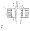
- a rotor 10 in this embodiment includes a core 11 and a shaft 12 to which the core 11 is fixed as shown in FIGs. 1 and 2.
- FIG. 2 is a cross-sectional view taken along a line A-A in FIG. 1 .
- the core 11 of the rotor 10 in this embodiment is made of laminated steel sheets in which permanent magnets 14 are embedded in predetermined positions. This rotor 10 is to be used in a motor of an interior permanent magnet type and inner-rotor type.
- the core 11 is formed with several types of through holes 23, 24, 25, and 26 as shown in FIG. 1 .
- the through holes 23 provided on an outermost circumferential side of those through holes, the permanent magnets 14 are embedded to penetrate through the core 11 in the laminating direction.
- the through holes 23 are arranged evenly in almost all directions. It is to be noted that the core 11 in the present embodiment is formed with sixteen through holes 23 in total.
- FIG. 1 a plurality of the through holes 24 are arranged on a more inner side than the through holes 23 in the core 11 as shown in FIG. 1 .
- These through holes 24 are made void to reduce the weight of the core 11.
- the through holes 25 used for welding are formed in two, upper and lower, positions in the figure.
- the through holes 25 are somewhat different in shape from the through holes 24.
- the through hole 26 for shaft is formed in a rotation center of the core 11.
- This through hole 26 is designed with such a diameter as to permit a shaft to be just fitted therein.
- FIGs. 1 and 2 show a state where the shaft 12 is inserted through the through hole 26.
- Each through hole 25 for welding is formed very close to the through hole 26 for shaft as shown in FIG. 1 . That is, a wall face 25a of each through hole 25, located close to the through hole 26 for shaft, is formed in a position adjacent to a wall face of the through hole 26 for shaft.
- a bridge portion 28 is provided between each wall face 25a and the through hole 26 for shaft. Specifically, the bridge portions 28 partition the through holes 25 for welding and the through hole 26 for shaft.
- Each bridge portion 28 is formed with a welded trace 29 passing through the bridge portion 28 to extend from the wall face 25a to a part of the shaft 12.
- This welded trace 29 is linearly formed over the laminating direction of the core 11 as shown in FIG. 2 .
- each welded trace 29 is formed in the core 11 to extend throughout its length in the axial direction of the shaft 12.
- the welded traces 29 are welded marks formed by irradiating an electron beam from the through holes 25 toward the wall faces 25a.
- the welded traces 29 represent that, in all the steel sheets constituting the core 11, the bridge portions 28 and a part of the face of the shaft 12 are welded and melted together into an integral structure. Simultaneously, parts of the steel sheets constituting the core 11 are also melted together and made integral with each other through the welded traces 29. This prevents the rotation between the steel sheets of the core 11, the rotation of the core 11 around the shaft 12, and the movement of the core 11 in the axial direction of the shaft 12. Specifically, the core 11 and the shaft 12 are reliably fixed to each other through the welded traces 29.
- the shaft 12 corresponds to a rotation transmitting member.
- the wall face of the through hole 26 for shaft in the core 11 corresponds to a rotation-transmitting-member mounting end face and the wall face 25a of the through hole 25 for welding corresponds to a welding end face, respectively.
- the welded traces 29 extend across the bridge portions 28.
- the through hole 26 for shaft and each wall face 25a are located adjacently on both sides of each bridge portion 28. According to the present embodiment, for fixing the core 1 and the shaft 12, there is no need to place plate members in contact with end portions of the core 11 in the laminating direction or form a key groove in a shaft.
- the through holes 25 for welding are provided in two positions.
- the through hole(s) 25 may be formed in one position or three or more positions as long as the core 11 and the shaft 12 can be surely fixed to each other.
- the shape and the arrangement of the through holes 24 are not particularly limited to the above and may be variously modified if only the strength and the balance of the core 11 can be maintained appropriately.
- the through holes 24 and the through holes 25 for welding are eight in combination and in total.
- the shape of the through holes 25 for welding is shown as the shape of a stepped hole, which is somewhat different from the shape of the through holes 24.
- the through holes 25 for welding and the through holes 24 may be designed with completely different shapes.
- a method of manufacturing the rotor 10 in the present embodiment will be explained below. In this embodiment, the following four processes are performed to manufacture the rotor 10.
- each yoke 41 is punched out of an original sheet as shown in FIG. 3 .
- the yokes 41 having the same, almost circular-disc shape, are produced in the number needed for a core 11.
- each yoke 41 is simultaneously formed with through holes 43, 44, 45, and 46 by punching in positions corresponding to the through holes 23, 24, 25, and 26 of the core 11.
- each yoke 41 includes bridges 48, corresponding to the bridge portions 28 of the core 11, between each through hole 45 and the through hole 46 as shown in the figure.
- the desired number of the yokes 41 for the core 11 are laminated.
- the yokes 41 are laminated by aligning the through holes 43, 44, 45, and 46 respectively. Accordingly, the through holes 43 of the yokes 41 overlap one another, forming the through holes 23.
- the through holes 44, 45, and 46 of the yokes 41 overlap to form the through holes 24, 25, and 26 of the core 11 respectively.
- the permanent magnets may be embedded in the resultant through holes 23 just after the above process or in a later process.
- the shaft 12 separately manufactured is inserted through the aligned through holes 46 (the through hole 26 for shaft) of the yokes 41 laminated in the laminating process (2) until the shaft 12 is placed in an appropriate position.
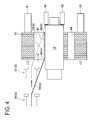
- electron beam welding is conducted by use of an electron gun 51.
- the gun 51 is first placed in an initial position (a position indicated by an alphabet (A) in the figure) so that an electron beam 52 fall on a bridge 48(A) of the yoke 41 located at an end (a left end in the figure) closest to the incident side. Then, the electron beam 52(A) is irradiated. A portion of the bridge 48(A) exposed to the electron beam 52(A) is thus melted. Further, a portion surrounding that melted portion is also melted and a molten area extends to the shaft 12. When this melted area hardens, the yokes 41 are fixed to the shaft 12 through the hardened area.
- the electron gun 51 is moved in the axial direction of the shaft 12 from left to right in FIG. 4 while emitting the electron beam 52.
- the incident direction of the electron beam 52 is determined within a plane defined by a radial direction of the core 11 and the axial direction of the shaft 12 in the through hole 25 for welding. Accordingly, the electron beam 52 is prevented from falling on any other portions than the bridges 48.
- the bridges 48 of all the yokes 41 are welded to the outer periphery of the shaft 12. Thus, welding is completed. If the permanent magnets have not been embedded in the prior laminating process (2), furthermore, this embedding work is performed after the welding.
- the rotor 10 is thus manufactured.
- This welding process (4) is preferably performed by pressing some parts as shown in FIG. 4 in order to appropriately maintain the laminated relation of the yokes 41.
- jigs 61 are placed at a right end of the core 11 in the figure and a leftmost one of the yokes 41 is pressed from left to right in the figure as indicated by hollow arrows.
- jigs 63 are also placed in contact with the shaft 12 to prevent displacement thereof.
- the core 11 may be entirely held or sandwiched in the lamination direction against displacement.
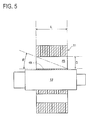
- the necessary space above the bridge 48 i.e., the size D of each through hole 45 in a radial direction of the core 11 is preferably determined in a range defined by the following expression: D > L x tan 10 ⁇ ° where L denotes a lamination thickness L of the core 11.
- the above incident angle ⁇ is more preferably set to 15° or more.
- the size D of the through hole 45 in the radial direction of the core 11 is determined in a range defined by the following expression: D ⁇ L x tan 15 ⁇ °
- width W (the size of the core 11 in a circumferential direction, see FIG. 3 ) of the through hole 45 has to be at least equal to or larger than a beam diameter of the electron beam 52.
- the width W is preferably 2 mm or more, for example.
- the range for passing the electron beam 52 is a range from a side of the through hole 45 defining the bridge 48 to a distance corresponding to a minimum value of the size D determined by any of the above expressions.
- Width V of the bridge 48 (the distance between the through hole 45 and the through hole 46, see FIG. 3 ) is a width of the bridge portion 28 in the core 11. That is, the width V is determined so that a melted area by the electron beam 52 reaches the shaft 12. It is appropriately smaller than the depth of a portion to be welded, for example, within a range of 1 mm to 5 mm. Therefore, the adjacent position of the welding end face and the rotation-transmitting-member mounting end face represent that the distance therebetween is smaller than the welding depth during welding in the case where the through holes are separated.
- the direction of moving the electron gun 51 may be reversed ((B) ⁇ (A)) from the above mentioned.
- the electron beam 52 may be swung to change an irradiating direction. This can also achieve appropriate welding.
- Another alternative is to fix the electron gun 51 and move a target such as the core 11 and others.
- the welding in this embodiment is conducted from one end side to over the range in the axial direction of the shaft 12. Alternatively, welding may be performed from both end sides to halves respectively. In this case, the term L in the expression for D is replaced with L/2.
- laser welding may be adopted.
- FIGs. 6 to 9 Other examples of the present embodiment are shown in FIGs. 6 to 9 .
- the welding method in the welding process (4) adopts fillet welding instead of the aforementioned lap welding.
- a through hole for passing the shaft 12 therethrough is designed so that a part of the through hole is expanded in a radial direction of the core.
- an electron beam is irradiated to a contact area between the wall face of the through hole and the shaft 12, thereby welding the shaft 12 and the core. That is, the through hole for welding and the through hole for shaft is configured as the continuous single through hole 64 or 74.
- the contact area of the wall face of the through hole 64 or 74 with respect to the shaft 12 corresponds to the rotation-transmitting-member mounting end face.
- a portion of the wall face of the through hole 64 or 74, in a range adjoining the contact area with the shaft 12, corresponds to the welding end face.
- the through holes for embedding the permanent magnets are omitted. Further, for weight reduction, additional through holes (corresponding to the through holes 24 in FIG. 1 ) may be formed, but are omitted.
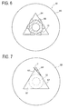
- a rotor 61 shown in FIG. 6 includes a core 63 and a shaft 12.
- the core 63 is formed with a regular triangular through hole 64 having such a size that the shaft 12 is inscribed in the through hole 64.
- the shaft 12 is inserted and fixed in the through hole 64.
- This core 63 consists of laminated yokes 65 each made of a magnetic steel sheet having a shape as shown in FIG. 7 .
- the shaft 12 is inserted in the through hole 64 of the laminated yokes 65 as indicated by a broken line in FIG. 7 .
- the through hole 64 in this example corresponds to a combination of the through hole 46 and the through holes 45 in FIG. 3 .
- the wall face of the through hole 64 and the outer periphery of the shaft 12 contact at three points as shown in FIG. 7 .
- a clearance 67 is left between the yokes 65 and the shaft 12. Therefore, through the use of each clearance 67, an electron beam can be irradiated as indicated by an arrow Y in the figure to a boundary in which the wall face of the through hole 64 and the outer periphery of the shaft 12 are in contact with each other.
- the core 63 and the shaft 12 can be welded to each other.
- the electron gun or the core 63 is moved in the axial direction of the shaft 12, so that the entire core 63 in the lamination direction is welded.
- welded traces 68 are formed as shown in FIG. 6 , whereby fixing the core 63 to the shaft 12.
- Six boundaries are present between the wall face of the through hole 64 and the shaft 12.
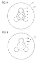
- a rotor 71 as shown in FIG. 8 is also adopted.
- a core 73 of this rotor 71 is formed with a through hole 74 and constituted of yokes 75 shown in FIG. 9 in a laminated configuration.
- This through hole 74 is formed with expanded portions 74b in three positions as well as a circumference portion 74a conforming to the outer periphery of the shaft 12.
- the shaft 12 is inserted into this through hole 74 as indicated by a broken line in FIG. 9 .
- the circumference portion 74a corresponds to the rotation-transmitting-member mounting end face and a wall face of each expanded portion 74b, within a range adjoining the outer circumference portion 74a, corresponds to the welding end face. They are also positioned adjacent to each other in this example.
- an electron beam can be irradiated from each expanded portion 74b toward a boundary where the wall face of the through hole 74 and the outer periphery of the shaft 12 contact with each other.
- the core 73 and the shaft 12 can be welded to each other.
- the rotor 71 formed with welded traces 78 is obtained.
- the core 11 is partly formed with the through holes 25 for welding adjacent to the through hole 26 for shaft in which the shaft 12 is inserted. Since the welded traces 29 are formed extending from the through holes 25 for welding to the shaft 12, all the yokes 41 constituting the core 11 and the shaft 12 are reliably fixed to each other. By welding, each yoke 41 is fixed in all directions. Thus, no additional process for fixing is needed. Further, conventional plate members holding both ends of the core 11 in the lamination direction, spaces for bending, and the like are not necessary. Consequently, a rotor easily enables size reduction and weight reduction of a rotary machine and is manufacturable in the minimum number of working processes.
- the outer shape of the shaft is not limited to cylindrical but may be designed in polygonal prism, spline, serration, etc.
- a key and a key groove may be added in the shaft and the core for engagement therebetween.
- a flange may be provided in the shaft to receive one side of the core in the lamination direction.
- the shaft may be not only an integral form but also a separate form.
- the steel sheets of the core may be fixed in advance by bending, welding, adhering, resin molding, or the like.
- the core may be made of a plurality of split core members separated in a circumferential direction.
- the invention may be applied not only to the interior permanent magnet (IPM) type motor but also a surface permanent magnet (SPM) type motor with magnets arranged in a rotor surface. Further, the invention can be applied not only to the inner-rotor type but also an outer-rotor type.
Landscapes
- Engineering & Computer Science (AREA)
- Power Engineering (AREA)
- Manufacturing & Machinery (AREA)
- Iron Core Of Rotating Electric Machines (AREA)
- Manufacture Of Motors, Generators (AREA)
- Permanent Field Magnets Of Synchronous Machinery (AREA)
Abstract
Description
- The present invention relates to a rotor including a core made of laminated steel plates and a rotation transmitting member for transmitting rotation of the core to the outside or rotation from the outside to the core, and a method of manufacturing the rotor. More particularly, the present invention relates to a technique of reliably fixing the core and the rotation transmitting member.
- Heretofore, some rotors to be used in a rotary machine are configured such that a core made of an assembly of magnetic steel sheets laminated is fixed to a rotation transmitting member. To appropriately transmit rotation of the rotation transmitting member to the core, such configuration needs reliable fixation between the core and the rotation transmitting member. The rotation transmitting member is for example a shaft for a rotor of an inner-rotor type rotary machine. It is necessary to prevent all of the rotation between the steel sheets constituting the core, the axial rotation between the core and the shaft, and the sliding of the core in the axial direction of the shaft. For preventing the rotation between the steel sheets, for instance, it is well known that the steel sheets are slightly bent (see Patent Literatures 1 and 2).
- For preventing the rotation between the core and the shaft, it is known that a key and a key groove, both being engageable with each other, are formed in the core and the shaft respectively. For preventing the sliding of the core in the axial direction of the shaft, further, it is known that plate members are placed in contact with both ends of the laminated steel sheets in the laminating direction and the plate members are bent (swaged) to the shaft to thereby hold and fix the laminated sheets between the plate members. It is also known that a shaft is provided with a flange at one end side in the axial direction to fix the steel sheets assembly (see Patent Literature 1 for example).
- Furthermore, another technique is also known in which the steel sheets assembly is fitted on an outer periphery of a core back and fixed to a shaft through this core back (see Patent Literature 2 for example). In this technique, the core back is fixed to the shaft. The core back is formed with a plurality of holes and each sheet is fixed to the core back through the holes by laser welding. Accordingly, this configuration is provided with a space or clearance enough for insertion of a laser head between the core back and the shaft.
-
- Patent Literature 1:
-
JP2007-124752A - Patent Literature 2:
-
JP2002-136067A - However, the aforementioned conventional techniques have the following disadvantages. In any techniques, separate working processes are carried out to fix the steel sheets of the core to each other and to fix the core to the shaft. Thus, the number of working processes is generally large. In this regard, there is a demand for minimizing the number of working processes.
- In any techniques, further, both ends of the core in the laminating direction are held by members such as the plate member, the flange, or the core back and fixed to the shaft through those members. Accordingly, a space is necessary to place those members. In Patent Literature 2 mentioned above, the space for laser welding is needed between the core back and the shaft. To achieve further size reduction and weight reduction of the rotary machine, it is desired to minimize the members and the spaces.
- The present invention has been made to solve the above problems of the conventional techniques and has a purpose to provide a rotor easily enabling size reduction and weight reduction of a rotary machine and being manufacturable in the minimum number of working processes, and a method of manufacturing the rotor.
- To achieve the above purpose, one aspect of the invention provides a rotor including a core made of laminated steel sheets and formed with a rotation-transmitting-member mounting end face extending over a lamination direction and a rotation transmitting member mounted to the mounting end face of the core, wherein the core is formed with a welding end face extending over the lamination direction and in a position adjacent to the rotation-transmitting-member mounting end face, and a welded trace is formed in the welding end face over in the lamination direction of the core, the welded trace extending to the rotation transmitting member.
- According to the rotor in the above aspect, the welding end face is formed adjacent to the rotation-transmitting-member mounting end face to which the rotation transmitting member is mounted in the core. Herein, the adjacent position represents a position in which the core and the rotation transmitting member are melted together by welding and hardened into integral form. Since the welding end face is formed with the welded trace extending to the rotation transmitting member, it is found that the core and the rotation transmitting member are fixed to each other by welding. The welded trace is formed over the lamination direction of the core, so that all the laminated steel sheets constituting the core are fixed to the rotation transmitting member. Accordingly, the rotor easily enables size reduction and weight reduction of a rotary machine and is manufacturable in the reduced number of working processes.
- In the above aspect of the invention, preferably, the rotation transmitting member is a shaft placed through a rotation center of the rotor, the core is formed with a through hole for shaft for inserting the shaft therethrough and a through hole for welding provided around the through hole for shaft, the through holes extending over the lamination direction, the rotation-transmitting-member mounting end face is a wall face of the through hole for shaft, and the welding end face is a wall face of the through hole for welding, on a side close to the through hole for shaft.
With this configuration, through the use of the through hole for welding, the welding is conducted from the welding end face toward the through hole for shaft to melt them to extend to the shaft. - In the above aspect of the invention, more preferably, the through hole for welding has a size of 2 mm or more in a circumferential direction of the core and a size D in a radial direction of the core determined to satisfy a relation of:

where L denotes a lamination thickness of the core.
With this configuration, a beam can be irradiated from one end of the core in the lamination direction up to the other end. - The above aspect of the invention may be configured such that the rotation transmitting member is a shaft placed through a rotation center of the rotor, the core is formed with a through hole for inserting the shaft therethrough, the through hole extending over the lamination direction, the rotation-transmitting-member mounting end face is a part of a wall face of the through hole, and the welding end face is a portion of a wall face of the through hole, the portion adjoining the rotation-transmitting-member mounting end face.
With this configuration, through the use of the through hole, the boundary between the wall face of the through hole and the shaft is welded. Thus, both are melted so as to extend to the shaft. - Another aspect of the invention provides a method of manufacturing a rotor including a core made of laminated steel sheets and formed with a rotation-transmitting-member mounting end face extending over a lamination direction and a rotation transmitting member mounted to the mounting end face of the core, the method comprising the steps of: mounting the rotation transmitting member to a rotation-transmitting-member mounting end face of the core made by laminating a plurality of steel sheets each having the rotation-transmitting-member mounting end face and a welding end face formed in a position adjacent to the rotation-transmitting-member mounting end face; and welding a range from the welding end face to the rotation transmitting member by irradiating a beam (an electron beam or a laser beam) to the range over the lamination direction of the core.
According to this aspect, the core can be produced by laminating steel sheets to form the rotation-transmitting-member mounting end face and the welding end face. Furthermore, the rotation transmitting member is mounted to the core and then welded from the welding end face. Accordingly, the rotor formed with the welded trace can be easily manufactured. - In the above aspect, preferably, the welding step includes moving a beam irradiating portion in a lamination direction of the core.
With this configuration, welding can be easily conducted over the lamination direction. - According to the rotor and the manufacturing method thereof in the above aspects of the present invention, it is possible to easily reduce the size and the weight of a rotary machine and manufacture the rotor in the reduced number of working processes.
-
-
FIG. 1 is a cross-sectional view showing a rotor in an embodiment; -
FIG. 2 is a cross-sectional view showing the rotor in the embodiment; -
FIG. 3 is an explanatory view showing a yoke in a manufacturing process of the rotor; -
FIG. 4 is an explanatory view showing a welding process; -
FIG. 5 is an explanatory view showing the size of a through hole; -
FIG. 6 is a cross-sectional view showing a structure of a rotor in another example; -
FIG. 7 is an explanatory view showing the shape of a yoke in the example shown inFIG. 6 ; -
FIG. 8 is a cross-sectional view showing a structure of a rotor in another example; and -
FIG. 9 is an explanatory view showing the shape of a yoke in the example shown inFIG. 8 . - A detailed description of a preferred embodiment of the present invention will now be given referring to the accompanying drawings. In the present embodiment, the invention is applied to a rotor in which a core consisting of laminated steel sheets is fixed to a shaft.
- A
rotor 10 in this embodiment includes acore 11 and ashaft 12 to which thecore 11 is fixed as shown inFIGs. 1 and2. FIG. 2 is a cross-sectional view taken along a line A-A inFIG. 1 . Thecore 11 of therotor 10 in this embodiment is made of laminated steel sheets in whichpermanent magnets 14 are embedded in predetermined positions. Thisrotor 10 is to be used in a motor of an interior permanent magnet type and inner-rotor type. - The
core 11 is formed with several types of throughholes FIG. 1 . In the throughholes 23 provided on an outermost circumferential side of those through holes, thepermanent magnets 14 are embedded to penetrate through the core 11 in the laminating direction. The through holes 23 are arranged evenly in almost all directions. It is to be noted that the core 11 in the present embodiment is formed with sixteen throughholes 23 in total. - Further, a plurality of the through
holes 24 are arranged on a more inner side than the throughholes 23 in the core 11 as shown inFIG. 1 . These throughholes 24 are made void to reduce the weight of thecore 11. The through holes 25 used for welding are formed in two, upper and lower, positions in the figure. The through holes 25 are somewhat different in shape from the through holes 24. In a rotation center of the core 11, the throughhole 26 for shaft is formed. This throughhole 26 is designed with such a diameter as to permit a shaft to be just fitted therein.FIGs. 1 and2 show a state where theshaft 12 is inserted through the throughhole 26. - Each through
hole 25 for welding is formed very close to the throughhole 26 for shaft as shown inFIG. 1 . That is, awall face 25a of each throughhole 25, located close to the throughhole 26 for shaft, is formed in a position adjacent to a wall face of the throughhole 26 for shaft. In thecore 11, abridge portion 28 is provided between eachwall face 25a and the throughhole 26 for shaft. Specifically, thebridge portions 28 partition the throughholes 25 for welding and the throughhole 26 for shaft. - Each
bridge portion 28 is formed with a weldedtrace 29 passing through thebridge portion 28 to extend from thewall face 25a to a part of theshaft 12. This weldedtrace 29 is linearly formed over the laminating direction of the core 11 as shown inFIG. 2 . Specifically, each weldedtrace 29 is formed in the core 11 to extend throughout its length in the axial direction of theshaft 12. The welded traces 29 are welded marks formed by irradiating an electron beam from the throughholes 25 toward the wall faces 25a. - The welded traces 29 represent that, in all the steel sheets constituting the
core 11, thebridge portions 28 and a part of the face of theshaft 12 are welded and melted together into an integral structure. Simultaneously, parts of the steel sheets constituting the core 11 are also melted together and made integral with each other through the welded traces 29. This prevents the rotation between the steel sheets of the core 11, the rotation of thecore 11 around theshaft 12, and the movement of the core 11 in the axial direction of theshaft 12. Specifically, thecore 11 and theshaft 12 are reliably fixed to each other through the welded traces 29. - In the present embodiment, the
shaft 12 corresponds to a rotation transmitting member. The wall face of the throughhole 26 for shaft in thecore 11 corresponds to a rotation-transmitting-member mounting end face and thewall face 25a of the throughhole 25 for welding corresponds to a welding end face, respectively. The welded traces 29 extend across thebridge portions 28. Thus, the throughhole 26 for shaft and eachwall face 25a are located adjacently on both sides of eachbridge portion 28. According to the present embodiment, for fixing the core 1 and theshaft 12, there is no need to place plate members in contact with end portions of the core 11 in the laminating direction or form a key groove in a shaft. - Herein, the through
holes 25 for welding are provided in two positions. Alternatively, the through hole(s) 25 may be formed in one position or three or more positions as long as thecore 11 and theshaft 12 can be surely fixed to each other. The shape and the arrangement of the throughholes 24 are not particularly limited to the above and may be variously modified if only the strength and the balance of the core 11 can be maintained appropriately. In the present embodiment, the throughholes 24 and the throughholes 25 for welding are eight in combination and in total. In the figure of the present embodiment, the shape of the throughholes 25 for welding is shown as the shape of a stepped hole, which is somewhat different from the shape of the through holes 24. Alternatively, the throughholes 25 for welding and the throughholes 24 may be designed with completely different shapes. - A method of manufacturing the
rotor 10 in the present embodiment will be explained below. In this embodiment, the following four processes are performed to manufacture therotor 10. - (1) Punching process;
- (2) Laminating process;
- (3) Shaft inserting process; and
- (4) Welding process.
- Firstly, in the punching process (1), a
yoke 41 is punched out of an original sheet as shown inFIG. 3 . Theyokes 41 having the same, almost circular-disc shape, are produced in the number needed for acore 11. At that time, eachyoke 41 is simultaneously formed with throughholes holes core 11. In this stage, eachyoke 41 includesbridges 48, corresponding to thebridge portions 28 of the core 11, between each throughhole 45 and the throughhole 46 as shown in the figure. - Secondly, in the laminating process (2), the desired number of the
yokes 41 for the core 11 are laminated. At that time, theyokes 41 are laminated by aligning the throughholes holes 43 of theyokes 41 overlap one another, forming the through holes 23. Similarly, the throughholes yokes 41 overlap to form the throughholes holes 23 just after the above process or in a later process. - In the shaft inserting process (3), subsequently, the
shaft 12 separately manufactured is inserted through the aligned through holes 46 (the throughhole 26 for shaft) of theyokes 41 laminated in the laminating process (2) until theshaft 12 is placed in an appropriate position. - In the welding process (4), as shown in
FIG. 4 , electron beam welding is conducted by use of anelectron gun 51. In this embodiment, thegun 51 is first placed in an initial position (a position indicated by an alphabet (A) in the figure) so that anelectron beam 52 fall on a bridge 48(A) of theyoke 41 located at an end (a left end in the figure) closest to the incident side. Then, the electron beam 52(A) is irradiated. A portion of the bridge 48(A) exposed to the electron beam 52(A) is thus melted. Further, a portion surrounding that melted portion is also melted and a molten area extends to theshaft 12. When this melted area hardens, theyokes 41 are fixed to theshaft 12 through the hardened area. - Further, the
electron gun 51 is moved in the axial direction of theshaft 12 from left to right inFIG. 4 while emitting theelectron beam 52. Herein, the incident direction of theelectron beam 52 is determined within a plane defined by a radial direction of thecore 11 and the axial direction of theshaft 12 in the throughhole 25 for welding. Accordingly, theelectron beam 52 is prevented from falling on any other portions than thebridges 48. When theelectron beam 52 reaches an end position (B), thebridges 48 of all theyokes 41 are welded to the outer periphery of theshaft 12. Thus, welding is completed. If the permanent magnets have not been embedded in the prior laminating process (2), furthermore, this embedding work is performed after the welding. Therotor 10 is thus manufactured. - In this welding process (4), the
bridge 48 of eachyoke 41 is welded to theshaft 12, forming the weldedtrace 29 shown inFIG. 1 . Consequently, theyokes 41 of the core 11 are fixed to theshaft 12 respectively. This fixing can be achieved simply by the welding process, whereby preventing the rotation between theyokes 41, the axial rotation between the core 11 and theshaft 12, and sliding of the core 11 in the axial direction of theshaft 12. - This welding process (4) is preferably performed by pressing some parts as shown in
FIG. 4 in order to appropriately maintain the laminated relation of theyokes 41. For instance, it is preferable that jigs 61 are placed at a right end of the core 11 in the figure and a leftmost one of theyokes 41 is pressed from left to right in the figure as indicated by hollow arrows. In this figure, furthermore, jigs 63 are also placed in contact with theshaft 12 to prevent displacement thereof. Alternatively, thecore 11 may be entirely held or sandwiched in the lamination direction against displacement. - In this welding process (4), there needs some space above the
bridge 48 in the figure to direct theelectron beam 52 to a farthest side (a right end inFIG. 4 ) from theelectron gun 51. Especially, for appropriately welding a portion exposed to theelectron beam 52, it is essential to set an incident angle θ to a welding surface at least 10° or more as shown inFIG. 5 . Accordingly, the necessary space above thebridge 48, i.e., the size D of each throughhole 45 in a radial direction of thecore 11 is preferably determined in a range defined by the following expression:
where L denotes a lamination thickness L of thecore 11. - The above incident angle θ is more preferably set to 15° or more. In this case, the size D of the through
hole 45 in the radial direction of thecore 11 is determined in a range defined by the following expression:
Further, width W (the size of the core 11 in a circumferential direction, seeFIG. 3 ) of the throughhole 45 has to be at least equal to or larger than a beam diameter of theelectron beam 52. In a range of the throughhole 45 for passing theelectron beam 52, the width W is preferably 2 mm or more, for example. The range for passing theelectron beam 52 is a range from a side of the throughhole 45 defining thebridge 48 to a distance corresponding to a minimum value of the size D determined by any of the above expressions. - Width V of the bridge 48 (the distance between the through
hole 45 and the throughhole 46, seeFIG. 3 ) is a width of thebridge portion 28 in thecore 11. That is, the width V is determined so that a melted area by theelectron beam 52 reaches theshaft 12. It is appropriately smaller than the depth of a portion to be welded, for example, within a range of 1 mm to 5 mm. Therefore, the adjacent position of the welding end face and the rotation-transmitting-member mounting end face represent that the distance therebetween is smaller than the welding depth during welding in the case where the through holes are separated. - In this welding process (4), naturally, the direction of moving the
electron gun 51 may be reversed ((B) → (A)) from the above mentioned. Instead of moving theelectron gun 51, theelectron beam 52 may be swung to change an irradiating direction. This can also achieve appropriate welding. Another alternative is to fix theelectron gun 51 and move a target such as thecore 11 and others. The welding in this embodiment is conducted from one end side to over the range in the axial direction of theshaft 12. Alternatively, welding may be performed from both end sides to halves respectively. In this case, the term L in the expression for D is replaced with L/2. Instead of the electron beam welding, laser welding may be adopted. - Other examples of the present embodiment are shown in
FIGs. 6 to 9 . In those examples, the welding method in the welding process (4) adopts fillet welding instead of the aforementioned lap welding. Specifically, instead of thebridges 48 between the throughholes 25 for welding and the throughhole 26 for shaft, a through hole for passing theshaft 12 therethrough is designed so that a part of the through hole is expanded in a radial direction of the core. Through a clearance between the expanded through hole (a throughhole 64 inFIG. 6 and a throughhole 74 inFIG. 8 ) and ashaft 12, an electron beam is irradiated to a contact area between the wall face of the through hole and theshaft 12, thereby welding theshaft 12 and the core. That is, the through hole for welding and the through hole for shaft is configured as the continuous single throughhole - In those cases, the contact area of the wall face of the through
hole shaft 12 corresponds to the rotation-transmitting-member mounting end face. A portion of the wall face of the throughhole shaft 12, corresponds to the welding end face. These are locations where theshaft 12 and the core are melted together by irradiation of the electron beam to the boundary therebetween. Accordingly, adjacent positions of the welding end face and the rotation-transmitting-member mounting end face represent the range in which they are meltable by irradiation of the electron beam in the case where the through holes are continuous. - In those figures, the through holes for embedding the permanent magnets (corresponding to the through
holes 23 inFIG. 1 ) are omitted. Further, for weight reduction, additional through holes (corresponding to the throughholes 24 inFIG. 1 ) may be formed, but are omitted. - A
rotor 61 shown inFIG. 6 includes acore 63 and ashaft 12. Thecore 63 is formed with a regular triangular throughhole 64 having such a size that theshaft 12 is inscribed in the throughhole 64. Theshaft 12 is inserted and fixed in the throughhole 64. Thus therotor 61 is completed. Thiscore 63 consists oflaminated yokes 65 each made of a magnetic steel sheet having a shape as shown inFIG. 7 . Theshaft 12 is inserted in the throughhole 64 of thelaminated yokes 65 as indicated by a broken line inFIG. 7 . - Specifically, the through
hole 64 in this example corresponds to a combination of the throughhole 46 and the throughholes 45 inFIG. 3 . There is no area corresponding to thebridges 48. Three portions of the wall face of the throughhole 64, at which theyokes 65 and theshaft 12 are in contact with each other, correspond to the rotation-transmitting-member mounting end faces. Further, other portions of the wall face of the throughhole 64 slightly apart from theshaft 12, continuous from both sides of each rotation-transmitting-member mounting end face and in a range where theshaft 12 and the core 63 are meltable together by welding, correspond to the welding end faces. Consequently, in those examples, the end faces are placed adjacently. - In this example, the wall face of the through
hole 64 and the outer periphery of theshaft 12 contact at three points as shown inFIG. 7 . In each of three apexes of the throughhole 64, aclearance 67 is left between theyokes 65 and theshaft 12. Therefore, through the use of eachclearance 67, an electron beam can be irradiated as indicated by an arrow Y in the figure to a boundary in which the wall face of the throughhole 64 and the outer periphery of theshaft 12 are in contact with each other. Thus, at the boundary, thecore 63 and theshaft 12 can be welded to each other. - Moreover, the electron gun or the
core 63 is moved in the axial direction of theshaft 12, so that theentire core 63 in the lamination direction is welded. As a result, welded traces 68 are formed as shown inFIG. 6 , whereby fixing the core 63 to theshaft 12. Six boundaries are present between the wall face of the throughhole 64 and theshaft 12. Thus, when all the boundaries are subjected to welding, therotor 61 formed with the welded traces 68 at six positions as shown in the figure is obtained. It is not always necessary to weld all six positions as long as appropriate fixing can be achieved. - A
rotor 71 as shown inFIG. 8 is also adopted. Acore 73 of thisrotor 71 is formed with a throughhole 74 and constituted ofyokes 75 shown inFIG. 9 in a laminated configuration. This throughhole 74 is formed with expandedportions 74b in three positions as well as acircumference portion 74a conforming to the outer periphery of theshaft 12. Theshaft 12 is inserted into this throughhole 74 as indicated by a broken line inFIG. 9 . In this example, thecircumference portion 74a corresponds to the rotation-transmitting-member mounting end face and a wall face of each expandedportion 74b, within a range adjoining theouter circumference portion 74a, corresponds to the welding end face. They are also positioned adjacent to each other in this example. - Therefore, an electron beam can be irradiated from each expanded
portion 74b toward a boundary where the wall face of the throughhole 74 and the outer periphery of theshaft 12 contact with each other. At each boundary, thecore 73 and theshaft 12 can be welded to each other. As shown inFIG. 8 , therotor 71 formed with weldedtraces 78 is obtained. - According to the present embodiment explained in detail above, the
core 11 is partly formed with the throughholes 25 for welding adjacent to the throughhole 26 for shaft in which theshaft 12 is inserted. Since the welded traces 29 are formed extending from the throughholes 25 for welding to theshaft 12, all theyokes 41 constituting thecore 11 and theshaft 12 are reliably fixed to each other. By welding, eachyoke 41 is fixed in all directions. Thus, no additional process for fixing is needed. Further, conventional plate members holding both ends of the core 11 in the lamination direction, spaces for bending, and the like are not necessary. Consequently, a rotor easily enables size reduction and weight reduction of a rotary machine and is manufacturable in the minimum number of working processes. - The above embodiments are mere examples and do not limit the present invention. The invention may be embodied in other specific forms without departing from the essential characteristics thereof.
For instance, the outer shape of the shaft is not limited to cylindrical but may be designed in polygonal prism, spline, serration, etc. Further, a key and a key groove may be added in the shaft and the core for engagement therebetween. A flange may be provided in the shaft to receive one side of the core in the lamination direction. The shaft may be not only an integral form but also a separate form. - For instance, the steel sheets of the core may be fixed in advance by bending, welding, adhering, resin molding, or the like. Further, the core may be made of a plurality of split core members separated in a circumferential direction. The invention may be applied not only to the interior permanent magnet (IPM) type motor but also a surface permanent magnet (SPM) type motor with magnets arranged in a rotor surface. Further, the invention can be applied not only to the inner-rotor type but also an outer-rotor type.
-
- 10, 61, 71
- Rotor
- 11, 63, 73
- Core
- 12
- Shaft
- 25
- Through hole for welding
- 26
- Through hole for shaft
- 29
- Welded trace
- 64, 74
- Through hole
Claims (6)
- A rotor including a core made of laminated steel sheets and formed with a rotation-transmitting-member mounting end face extending over a lamination direction and a rotation transmitting member mounted to the mounting end face of the core, wherein
the core is formed with a welding end face extending over the lamination direction and in a position adjacent to the rotation-transmitting-member mounting end face, and
a welded trace is formed in the welding end face over in the lamination direction of the core, the welded trace extending to the rotation transmitting member. - The rotor according to claim 1, wherein the rotation transmitting member is a shaft placed through a rotation center of the rotor,
the core is formed with a through hole for shaft for inserting the shaft therethrough and a through hole for welding provided around the through hole for shaft, the through holes extending over the lamination direction,
the rotation-transmitting-member mounting end face is a wall face of the through hole for shaft, and
the welding end face is a wall face of the through hole for welding, on a side close to the through hole for shaft. - The rotor according to claim 2, wherein the through hole for welding has a size of 2 mm or more in a circumferential direction of the core and a size D in a radial direction of the core determined to satisfy a relation of:

where L denotes a lamination thickness of the core. - The rotor according to claim 1, wherein
the rotation transmitting member is a shaft placed through a rotation center of the rotor,
the core is formed with a through hole for inserting the shaft therethrough, the through hole extending over the lamination direction,
the rotation-transmitting-member mounting end face is a part of a wall face of the through hole, and
the welding end face is a portion of a wall face of the through hole, the portion adjoining the rotation-transmitting-member mounting end face. - A method of manufacturing a rotor including a core made of laminated steel sheets and formed with a rotation-transmitting-member mounting end face extending over a lamination direction and a rotation transmitting member mounted to the mounting end face of the core, the method comprising the steps of:mounting the rotation transmitting member to a rotation-transmitting-member mounting end face of the core made by laminating a plurality of steel sheets each having the rotation-transmitting-member mounting end face and a welding end face formed in a position adjacent to the rotation-transmitting-member mounting end face; andwelding a range from the welding end face to the rotation transmitting member by irradiating a beam to the range over the lamination direction of the core.
- The rotor according to claim 5, wherein the welding step includes moving a beam irradiating portion in a lamination direction of the core.
Applications Claiming Priority (1)
| Application Number | Priority Date | Filing Date | Title |
|---|---|---|---|
| PCT/JP2009/067633 WO2011042984A1 (en) | 2009-10-09 | 2009-10-09 | Rotor and method for manufacturing same |
Publications (2)
| Publication Number | Publication Date |
|---|---|
| EP2487777A1 true EP2487777A1 (en) | 2012-08-15 |
| EP2487777A4 EP2487777A4 (en) | 2016-01-06 |
Family
ID=43856476
Family Applications (1)
| Application Number | Title | Priority Date | Filing Date |
|---|---|---|---|
| EP09850255.2A Withdrawn EP2487777A4 (en) | 2009-10-09 | 2009-10-09 | ROTOR AND METHOD FOR MANUFACTURING THE SAME |
Country Status (6)
| Country | Link |
|---|---|
| US (1) | US8669686B2 (en) |
| EP (1) | EP2487777A4 (en) |
| JP (1) | JP5126414B2 (en) |
| KR (1) | KR101224700B1 (en) |
| CN (1) | CN102292898B (en) |
| WO (1) | WO2011042984A1 (en) |
Families Citing this family (13)
| Publication number | Priority date | Publication date | Assignee | Title |
|---|---|---|---|---|
| CN102326316B (en) | 2010-03-15 | 2014-05-07 | 丰田自动车株式会社 | Rotor and manufacturing method thereof |
| JP5924194B2 (en) * | 2012-08-31 | 2016-05-25 | 株式会社デンソー | Multi-gap rotating electric machine |
| JP2014050210A (en) * | 2012-08-31 | 2014-03-17 | Hitachi Automotive Systems Ltd | Dynamo-electric machine |
| US20140097711A1 (en) * | 2012-10-05 | 2014-04-10 | Larry Kubes | One piece rotor hub/shaft for an electric machine and method |
| GB2506932A (en) * | 2012-10-15 | 2014-04-16 | Nissan Motor Mfg Uk Ltd | Laminated rotor assembly |
| JP6495747B2 (en) * | 2015-06-05 | 2019-04-03 | 株式会社三井ハイテック | Laminated iron core inspection device and laminated iron core inspection method |
| JP6696455B2 (en) * | 2017-02-15 | 2020-05-20 | トヨタ自動車株式会社 | Rotating electric machine rotor |
| DE102017104892B4 (en) * | 2017-03-08 | 2023-09-14 | Nidec Corporation | Housing for an electric motor |
| JP6915196B2 (en) * | 2017-09-26 | 2021-08-04 | 株式会社アイシン | Rotating machine |
| CN111295816A (en) * | 2017-10-31 | 2020-06-16 | 日本电产株式会社 | Rotor and motor |
| JP7266180B2 (en) | 2019-05-15 | 2023-04-28 | パナソニックIpマネジメント株式会社 | Rotor and motor with same |
| JP7287568B2 (en) * | 2020-03-04 | 2023-06-06 | 株式会社アイシン | Rotor and rotor manufacturing method |
| JP7670993B2 (en) * | 2020-06-30 | 2025-05-01 | 愛知製鋼株式会社 | Manufacturing method of rotor core, rotor core, high strength steel plate, and manufacturing method of high strength steel plate |
Family Cites Families (21)
| Publication number | Priority date | Publication date | Assignee | Title |
|---|---|---|---|---|
| JPS5475004A (en) * | 1977-11-28 | 1979-06-15 | Hitachi Ltd | Method for manufacturing rotor |
| JPS5734747A (en) * | 1980-08-08 | 1982-02-25 | Toshiba Corp | Rotary electric machine |
| JPS6046620B2 (en) * | 1980-10-24 | 1985-10-17 | 株式会社デンソー | Iron core for rotating electric machines |
| JPS5911745A (en) * | 1982-07-09 | 1984-01-21 | Toshiba Corp | Rotary electric machine |
| JP3050983B2 (en) * | 1992-01-20 | 2000-06-12 | 株式会社東芝 | Stator frame of rotating electric machine |
| FI91818C (en) * | 1992-08-21 | 1994-08-10 | Abb Stroemberg Drives Oy | Rotor structure of an electric machine |
| JPH09168258A (en) | 1995-12-14 | 1997-06-24 | Matsushita Electric Ind Co Ltd | How to assemble an amateur core |
| JPH10164802A (en) | 1996-11-27 | 1998-06-19 | Toshiba Corp | Iron core manufacturing method |
| JP3555377B2 (en) | 1997-03-12 | 2004-08-18 | 三菱電機株式会社 | Rotor and method of manufacturing rotor |
| JP2000116046A (en) | 1998-10-02 | 2000-04-21 | Miyachi Technos Corp | Motor rotor and method of assembling the same |
| JP2001298903A (en) * | 2000-04-10 | 2001-10-26 | Moric Co Ltd | Brushless dc motor |
| JP4590714B2 (en) * | 2000-10-23 | 2010-12-01 | パナソニック株式会社 | Brushless motor and manufacturing method thereof |
| JP2002136067A (en) | 2000-10-27 | 2002-05-10 | Nissan Motor Co Ltd | Rotor for magnet motor |
| GB0109847D0 (en) * | 2001-04-21 | 2001-06-13 | Johnson Electric Sa | Motor |
| JP3724447B2 (en) * | 2002-04-01 | 2005-12-07 | 日産自動車株式会社 | Rotor structure and manufacturing method thereof |
| JP3790824B2 (en) * | 2004-01-29 | 2006-06-28 | 三菱電機株式会社 | Rotor and method for manufacturing the same |
| TWI382634B (en) * | 2004-12-15 | 2013-01-11 | 松下電器產業股份有限公司 | Motor with double insulation structure and electronic machine equipped with the same |
| JP2006254662A (en) | 2005-03-14 | 2006-09-21 | Mitsubishi Electric Corp | Rotor and motor |
| JP4492521B2 (en) | 2005-10-26 | 2010-06-30 | トヨタ自動車株式会社 | Method for manufacturing rotor shaft |
| JP5231790B2 (en) * | 2007-11-20 | 2013-07-10 | 日本電産テクノモータ株式会社 | Motor rotor and motor |
| DE102007055542A1 (en) * | 2007-11-21 | 2009-06-04 | Bühler Motor GmbH | Rotor of an electric motor |
-
2009
- 2009-10-09 WO PCT/JP2009/067633 patent/WO2011042984A1/en not_active Ceased
- 2009-10-09 CN CN200980155423.8A patent/CN102292898B/en not_active Expired - Fee Related
- 2009-10-09 KR KR1020117017167A patent/KR101224700B1/en not_active Expired - Fee Related
- 2009-10-09 EP EP09850255.2A patent/EP2487777A4/en not_active Withdrawn
- 2009-10-09 US US13/145,864 patent/US8669686B2/en not_active Expired - Fee Related
- 2009-10-09 JP JP2011506515A patent/JP5126414B2/en not_active Expired - Fee Related
Non-Patent Citations (1)
| Title |
|---|
| See references of WO2011042984A1 * |
Also Published As
| Publication number | Publication date |
|---|---|
| JPWO2011042984A1 (en) | 2013-02-28 |
| CN102292898A (en) | 2011-12-21 |
| US8669686B2 (en) | 2014-03-11 |
| KR101224700B1 (en) | 2013-01-21 |
| CN102292898B (en) | 2014-07-02 |
| KR20110106897A (en) | 2011-09-29 |
| WO2011042984A1 (en) | 2011-04-14 |
| JP5126414B2 (en) | 2013-01-23 |
| US20120019097A1 (en) | 2012-01-26 |
| EP2487777A4 (en) | 2016-01-06 |
Similar Documents
| Publication | Publication Date | Title |
|---|---|---|
| EP2487777A1 (en) | Rotor and method for manufacturing same | |
| EP2549623A1 (en) | Rotor and process for production thereof | |
| KR100950829B1 (en) | Rotor of rotary electric machine, and manufacturing method thereof | |
| JP5278551B2 (en) | Rotor core for rotating electrical machine and manufacturing method thereof | |
| WO2017090571A1 (en) | Motor and method for manufacturing motor | |
| WO2010150592A1 (en) | Rotator core | |
| EP2768119B1 (en) | Method for producing a laminated rotor core | |
| US20140041207A1 (en) | Method for producing a motor rotor | |
| EP2149962B1 (en) | A magneto field type motor and a method of manufacturing it | |
| CN110366807B (en) | Laminated core for rotating electrical machine, method for manufacturing laminated core for rotating electrical machine, and rotating electrical machine | |
| EP3474427B1 (en) | Manufacturing method of core of rotating electrical machine, and core of rotating electrical machine | |
| JP2010110123A (en) | Laminate core and manufacturing method thereof | |
| JP6508102B2 (en) | Rotating electrical machine and method of manufacturing split stator steel plate | |
| JP7211128B2 (en) | Laminated structure manufacturing method | |
| EP4550631A1 (en) | Rotor manufacturing method and rotor | |
| JP4977576B2 (en) | Method for manufacturing iron core in rotor with permanent magnet and iron core | |
| JP2009100537A (en) | Method for manufacturing iron core in rotor with permanent magnet and iron core | |
| EP3385569A1 (en) | Laser-marked chain | |
| CN100399673C (en) | Iron core for motor and manufacturing method thereof | |
| CN111557071A (en) | Method for manufacturing rotor | |
| JP2009100535A (en) | Method for manufacturing iron core in rotor with permanent magnet and iron core | |
| JP2021048676A (en) | Manufacturing method of laminated core | |
| JP2005117709A (en) | Synchronous machine |
Legal Events
| Date | Code | Title | Description |
|---|---|---|---|
| PUAI | Public reference made under article 153(3) epc to a published international application that has entered the european phase |
Free format text: ORIGINAL CODE: 0009012 |
|
| 17P | Request for examination filed |
Effective date: 20110722 |
|
| AK | Designated contracting states |
Kind code of ref document: A1 Designated state(s): AT BE BG CH CY CZ DE DK EE ES FI FR GB GR HR HU IE IS IT LI LT LU LV MC MK MT NL NO PL PT RO SE SI SK SM TR |
|
| DAX | Request for extension of the european patent (deleted) | ||
| RAP1 | Party data changed (applicant data changed or rights of an application transferred) |
Owner name: TOYOTA JIDOSHA KABUSHIKI KAISHA |
|
| RA4 | Supplementary search report drawn up and despatched (corrected) |
Effective date: 20151209 |
|
| RIC1 | Information provided on ipc code assigned before grant |
Ipc: H02K 1/18 20060101AFI20151203BHEP |
|
| 17Q | First examination report despatched |
Effective date: 20160728 |
|
| STAA | Information on the status of an ep patent application or granted ep patent |
Free format text: STATUS: EXAMINATION IS IN PROGRESS |
|
| GRAP | Despatch of communication of intention to grant a patent |
Free format text: ORIGINAL CODE: EPIDOSNIGR1 |
|
| STAA | Information on the status of an ep patent application or granted ep patent |
Free format text: STATUS: GRANT OF PATENT IS INTENDED |
|
| INTG | Intention to grant announced |
Effective date: 20180131 |
|
| STAA | Information on the status of an ep patent application or granted ep patent |
Free format text: STATUS: THE APPLICATION IS DEEMED TO BE WITHDRAWN |
|
| 18D | Application deemed to be withdrawn |
Effective date: 20180612 |