EP2487756B1 - Electrical interconnection having magnetic conductive elements - Google Patents
Electrical interconnection having magnetic conductive elements Download PDFInfo
- Publication number
- EP2487756B1 EP2487756B1 EP12167529.2A EP12167529A EP2487756B1 EP 2487756 B1 EP2487756 B1 EP 2487756B1 EP 12167529 A EP12167529 A EP 12167529A EP 2487756 B1 EP2487756 B1 EP 2487756B1
- Authority
- EP
- European Patent Office
- Prior art keywords
- conductive
- magnetic
- elements
- slivers
- electrical
- Prior art date
- Legal status (The legal status is an assumption and is not a legal conclusion. Google has not performed a legal analysis and makes no representation as to the accuracy of the status listed.)
- Ceased
Links
- 230000005291 magnetic effect Effects 0.000 title claims description 77
- 230000005415 magnetization Effects 0.000 claims description 5
- 230000000717 retained effect Effects 0.000 claims description 5
- 230000005294 ferromagnetic effect Effects 0.000 claims description 4
- RYGMFSIKBFXOCR-UHFFFAOYSA-N Copper Chemical compound [Cu] RYGMFSIKBFXOCR-UHFFFAOYSA-N 0.000 claims description 3
- 239000011248 coating agent Substances 0.000 claims description 3
- 238000000576 coating method Methods 0.000 claims description 3
- 229910052802 copper Inorganic materials 0.000 claims description 2
- 239000010949 copper Substances 0.000 claims description 2
- PCHJSUWPFVWCPO-UHFFFAOYSA-N gold Chemical compound [Au] PCHJSUWPFVWCPO-UHFFFAOYSA-N 0.000 claims description 2
- 229910052737 gold Inorganic materials 0.000 claims description 2
- 239000010931 gold Substances 0.000 claims description 2
- 239000000696 magnetic material Substances 0.000 claims description 2
- 229910052761 rare earth metal Inorganic materials 0.000 claims description 2
- 150000002910 rare earth metals Chemical class 0.000 claims description 2
- 239000000463 material Substances 0.000 description 6
- 238000010586 diagram Methods 0.000 description 5
- 238000000926 separation method Methods 0.000 description 3
- 230000008602 contraction Effects 0.000 description 1
- 230000007423 decrease Effects 0.000 description 1
- 239000003302 ferromagnetic material Substances 0.000 description 1
- 230000004907 flux Effects 0.000 description 1
- 230000005298 paramagnetic effect Effects 0.000 description 1
Images



Classifications
-
- H—ELECTRICITY
- H01—ELECTRIC ELEMENTS
- H01R—ELECTRICALLY-CONDUCTIVE CONNECTIONS; STRUCTURAL ASSOCIATIONS OF A PLURALITY OF MUTUALLY-INSULATED ELECTRICAL CONNECTING ELEMENTS; COUPLING DEVICES; CURRENT COLLECTORS
- H01R11/00—Individual connecting elements providing two or more spaced connecting locations for conductive members which are, or may be, thereby interconnected, e.g. end pieces for wires or cables supported by the wire or cable and having means for facilitating electrical connection to some other wire, terminal, or conductive member, blocks of binding posts
- H01R11/11—End pieces or tapping pieces for wires, supported by the wire and for facilitating electrical connection to some other wire, terminal or conductive member
- H01R11/30—End pieces held in contact by a magnet
-
- H—ELECTRICITY
- H01—ELECTRIC ELEMENTS
- H01R—ELECTRICALLY-CONDUCTIVE CONNECTIONS; STRUCTURAL ASSOCIATIONS OF A PLURALITY OF MUTUALLY-INSULATED ELECTRICAL CONNECTING ELEMENTS; COUPLING DEVICES; CURRENT COLLECTORS
- H01R13/00—Details of coupling devices of the kinds covered by groups H01R12/70 or H01R24/00 - H01R33/00
- H01R13/02—Contact members
- H01R13/025—Contact members formed by the conductors of a cable end
Definitions
- the present invention relates generally to a system for electrically connecting components. More particularly, the present invention relates to an electrical interconnection configured to magnetically couple two or more conductive elements together to establish an electrical conductive path between the conductive elements.
- conductive wires are a copper wire. In many instances, these conductive wires are coated with a material that functions to both protect and insulate the wire. Conductive wires are manufactured in numerous "gauges" so that an appropriately sized wire may be selected for a specific application.
- Typical conductive wires are relatively stiff and are not designed to stretch when a tensile force is applied to the wire. Tensile forces are common when the wire is used in conjunction with a component that experiences vibration. Thus, wires that experience tensile forces have a tendency to snap in half when stretched, thereby destroying their use as an electrical conductive path. Furthermore, the stiffness and thermal contraction properties of the materials used to support or insulate the wire become a greater problem when the wire is used in a cold environment where the materials may become brittle and possibly shrink. It is not uncommon in these situations for the materials themselves to shear the wire, thereby destroying the conductive path. Conductive elements such as conductive wire braids have been developed which have the ability to stretch more than an ordinary strand of wire. However, the amount that the conductive wire braids may stretch is still rather limited.
- US3810258 discloses a system according to the preamble of claim 1.
- the present invention provides a system for providing an electrical connection, as set forth in claim 1.
- FIG. 1 is a diagram illustrating electrical interconnection 10, which falls outside the scope of the present invention and which includes first conductive element 12, second conductive element 14, first magnetic element 16, and second magnetic element 18. As shown in FIG. 1 , first magnetic element 16 is disposed within first conductive element 12, while second magnetic element 18 is disposed within second conductive element 14, as depicted by the broken-line outlines of the magnetic elements.
- first and second magnetic elements 12 and 14 When opposite poles of first and second magnetic elements 12 and 14 are placed close to one another, a magnetic attraction F forms between the two magnetic elements. As will be described in more detail to follow, when first and second magnetic elements 16 and 18 are magnetically coupled together, an electrical conductive path is formed between first conductive element 12 and second conductive element 14. Thus, when magnetically coupled together, first and second conductive elements 12 and 14 form a single electrically conductive element capable of transferring an electrical current.
- the first and second magnetic elements 16 and 18 may both be permanent magnets (i.e., a ferromagnetic material which has a significant retained magnetization).
- a permanent magnet is a rare earth magnet.
- one of the magnetic elements may be a paramagnetic or ferromagnetic type material that does not have the retained magnetization like a permanent magnet, but becomes magnetized when placed near a magnetic field.
- Electrical interconnection 10 is useful in any application where an electrical connection between two components is required, and may replace prior art conductive wires commonly used to provide an electrical conductive path between components. Particularly, the electrical interconnection of the present invention is useful in applications where conductive wires may be subject to very low temperatures, extreme vibration, or tensile forces that may cause the wires to break or become damaged.
- first and second conductive elements 12 and 14 are conductive braids, and first and second magnetic elements 16 and 18 are disposed within their respective conductive braids.
- first and second magnetic elements 16 and 18 may alternatively be coupled to an outer surface of their respective conductive element.
- conductive elements 12 and 14 are shown as each having one associated magnetic element, a plurality of magnetic elements may be used without departing from the intended scope of the present invention.
- the magnetic force of attraction F between first and second magnetic elements 16 and 18 provides a "quick disconnect" feature that is useful to quickly and easily interrupt the flow of current from one conductive element to the other.
- the electrical conductive path may be interrupted by separation of first and second magnetic elements 16 and 18. This may be accomplished by simply pulling magnetic elements 16 and 18 in opposite directions along the F-axis until first and second conductive elements 12 and 14 are no longer in contact. As a result, when first and second conductive elements 12 and 14 are no longer in contact, and electrical current cannot pass between them.
- electrical interconnection 10 is used to provide power to a sensor, the magnetic elements serve as a means to quickly disconnect (and re-connect) power to the sensor.
- first and second conductive elements 12 and 14 must remain below the Curie temperature of both magnetic elements 16 and 18. If the temperature of a conductive element exceeds the Curie temperature of its associated magnetic element, then the magnetic element will begin to lose any retained magnetization. As a result, the electrical conductive path may be broken due to the lack of a magnetic attraction between the magnetic elements.
- FIGS. 2A and 2B illustrate how an electrical interconnection as shown in FIG. 1 provides strain relief when a force, such as a tensile force, is applied to one or both of conductive elements 12 and 14.
- a force such as a tensile force
- FIG. 2A no tensile force is applied to either of the conductive elements, and center point C1 of first magnetic element 16 is aligned with center point C2 of second magnetic element 18.
- an electrical conductive path 20 is defined by the overlapping surface lengths of first and second magnetic elements 16 and 18.
- first conductive element 12 in direction Y1 and second conductive element 14 in direction Y2.
- These tensile forces have caused center point C1 of first magnetic element 16 to slide in direction Y1 and center point C2 of second magnetic element 18 to slide in direction Y2, thereby creating a separation ⁇ C between center points C1 and C2.
- the separation ⁇ C illustrates the strain relief element of the present invention, which exists due to the fact that first and second conductive elements 12 and 14 may be pulled apart in an axial direction relative to one another without losing electrical conductive path 20.
- first and second conductive elements 12 and 14 when a tensile force is applied to first and second conductive elements 12 and 14, the magnetic attraction formed between first and second magnetic elements 16 and 18 allows the conductive elements to slide relative to one another while maintaining the electrical conductive path 20.
- the amount that first and second conductive elements 12 and 14 may slide relative to one another is related to the lengths, placement, and number of magnetic elements associated with each conductive element. For example, the longer the magnetic regions of first and second conductive elements 12 and 14, the more they may be pulled relative to one another without losing the electrical conductive path 20 formed between them.
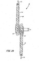
- FIG. 3 is a diagram illustrating electrical interconnection 10A, which is an embodiment of an electrical interconnection in accordance with the invention.
- electrical interconnection 10A includes first conductive element 12A, second conductive element 14A, first magnetic element 16A, and second magnetic element 18A.
- Electrical interconnection 10A is similar to electrical interconnection 10.
- first and second magnetic elements 16 and 18, which are themselves also conductive are coupled to an outer surface of their respective conductive elements, and a plurality of magnetic conductive slivers 22 is disposed between the magnetic elements.
- Magnetic conductive slivers 22 are configured to maintain electrical conductive path 20A between first and second conductive elements 12A and 14A when first and second magnetic elements 16A and 18A are separated, creating gap G between the conductive elements.
- the addition of magnetic conductive slivers 22 yields an example of a strain relief element since first and second conductive elements 12A and 14A may be pulled apart without breaking electrical conductive path 20A.
- each magnetic conductive sliver 22 aligns with a south pole "S” of either first magnetic element 16A or another magnetic conductive sliver 22.
- a south pole "S” of each magnetic conductive sliver 20 aligns with a north pole "N” of either second magnetic element 18A or another one of the magnetic conductive slivers 22. It should be noted that due to the small size of magnetic conductive slivers 22, the north and south poles of slivers 22 are not labeled in FIG. 3 .
- Magnetic conductive slivers 22 are able to maintain electrical conductive path 20A between first and second conductive elements 12A and 14A due to the magnetic attraction (i.e., the magnetic flux) present between first and second magnetic elements 16A and 18A. It is important to note that as the gap G between first and second magnetic elements 16A and 18A increases, the magnitude of the magnetic force of attraction between the magnetic elements decreases. Therefore, once gap G is large enough that the magnetic force of attraction weakens significantly, magnetic conductive slivers 22 will no longer be able to complete the electrical conductive path and current will no longer flow between first and second conductive elements 12A and 14A.
- the magnetic attraction i.e., the magnetic flux
- slivers 22 were referred to as "conductive magnetic slivers" above to indicate that in order for the slivers to conduct current, they must be both conductive as well as magnetic or ferromagnetic. Therefore, slivers 22 may be formed from a magnetic material and coated with, among other materials, copper or gold, in order to achieve both properties. However, any type of sliver that is both magnetic (or ferromagnetic) and conductive, whether manufactured with a conductive coating or not, is within the intended scope of the present invention.
Landscapes
- Coils Or Transformers For Communication (AREA)
- Details Of Connecting Devices For Male And Female Coupling (AREA)
- Electromagnets (AREA)
- Connections Effected By Soldering, Adhesion, Or Permanent Deformation (AREA)
Description
- The present invention relates generally to a system for electrically connecting components. More particularly, the present invention relates to an electrical interconnection configured to magnetically couple two or more conductive elements together to establish an electrical conductive path between the conductive elements.
- In the past, the simplest way to provide electrical power to a component or to receive electrical signal from a component was to connect a power source to the component with a conductive wire. One of the most common types of conductive wires is a copper wire. In many instances, these conductive wires are coated with a material that functions to both protect and insulate the wire. Conductive wires are manufactured in numerous "gauges" so that an appropriately sized wire may be selected for a specific application.
- Typical conductive wires are relatively stiff and are not designed to stretch when a tensile force is applied to the wire. Tensile forces are common when the wire is used in conjunction with a component that experiences vibration. Thus, wires that experience tensile forces have a tendency to snap in half when stretched, thereby destroying their use as an electrical conductive path. Furthermore, the stiffness and thermal contraction properties of the materials used to support or insulate the wire become a greater problem when the wire is used in a cold environment where the materials may become brittle and possibly shrink. It is not uncommon in these situations for the materials themselves to shear the wire, thereby destroying the conductive path. Conductive elements such as conductive wire braids have been developed which have the ability to stretch more than an ordinary strand of wire. However, the amount that the conductive wire braids may stretch is still rather limited.
- Thus, there exists a need for an electrical interconnection with increased versatility that is capable of providing an electrical conductive path under a wide range of operating conditions.
US3810258 discloses a system according to the preamble of claim 1. - The present invention provides a system for providing an electrical connection, as set forth in claim 1.
-
-
FIG. 1 is a diagram illustrating an electrical interconnection which falls outside the scope of the present invention, and which includes a first conductive clement and a second conductive element. -
FIGS. 2A and2B are diagrams illustrating how an electrical interconnection is configured to provide strain relief when a force, such as a tensile force, is applied to the first or second conductive elements. -
FIG. 3 is a diagram illustrating an embodiment of the present invention. -
FIG. 1 is a diagram illustratingelectrical interconnection 10, which falls outside the scope of the present invention and which includes firstconductive element 12, secondconductive element 14, firstmagnetic element 16, and secondmagnetic element 18. As shown inFIG. 1 , firstmagnetic element 16 is disposed within firstconductive element 12, while secondmagnetic element 18 is disposed within secondconductive element 14, as depicted by the broken-line outlines of the magnetic elements. - When opposite poles of first and second
magnetic elements magnetic elements conductive element 12 and secondconductive element 14. Thus, when magnetically coupled together, first and secondconductive elements - The first and second
magnetic elements -
Electrical interconnection 10 is useful in any application where an electrical connection between two components is required, and may replace prior art conductive wires commonly used to provide an electrical conductive path between components. Particularly, the electrical interconnection of the present invention is useful in applications where conductive wires may be subject to very low temperatures, extreme vibration, or tensile forces that may cause the wires to break or become damaged. - In the arrangement illustrated in
FIG. 1 , first and secondconductive elements magnetic elements magnetic elements conductive elements - The magnetic force of attraction F between first and second
magnetic elements magnetic elements magnetic elements conductive elements conductive elements electrical interconnection 10 is used to provide power to a sensor, the magnetic elements serve as a means to quickly disconnect (and re-connect) power to the sensor. - It is important to note that in order for the magnetic attraction F between first and second
magnetic elements conductive elements magnetic elements -
FIGS. 2A and2B illustrate how an electrical interconnection as shown inFIG. 1 provides strain relief when a force, such as a tensile force, is applied to one or both ofconductive elements FIG. 2A , no tensile force is applied to either of the conductive elements, and center point C1 of firstmagnetic element 16 is aligned with center point C2 of secondmagnetic element 18. As illustrated inFIG. 2A , an electricalconductive path 20 is defined by the overlapping surface lengths of first and secondmagnetic elements - Next, as shown in
FIG. 2B , a tensile force has now been applied to firstconductive element 12 in direction Y1 and secondconductive element 14 in direction Y2. These tensile forces have caused center point C1 of firstmagnetic element 16 to slide in direction Y1 and center point C2 of secondmagnetic element 18 to slide in direction Y2, thereby creating a separation ΔC between center points C1 and C2. The separation ΔC illustrates the strain relief element of the present invention, which exists due to the fact that first and secondconductive elements conductive path 20. In particular, when a tensile force is applied to first and secondconductive elements magnetic elements conductive path 20. It should be noted that the amount that first and secondconductive elements conductive elements conductive path 20 formed between them. -
FIG. 3 is a diagram illustratingelectrical interconnection 10A, which is an embodiment of an electrical interconnection in accordance with the invention. As illustrated inFIG. 3 ,electrical interconnection 10A includes firstconductive element 12A, secondconductive element 14A, firstmagnetic element 16A, and secondmagnetic element 18A.Electrical interconnection 10A is similar toelectrical interconnection 10. However, first and secondmagnetic elements conductive slivers 22 is disposed between the magnetic elements. Magneticconductive slivers 22 are configured to maintain electricalconductive path 20A between first and secondconductive elements magnetic elements conductive slivers 22 yields an example of a strain relief element since first and secondconductive elements conductive path 20A. - When first and second
magnetic elements conductive sliver 22 aligns with a south pole "S" of either firstmagnetic element 16A or another magneticconductive sliver 22. Similarly, a south pole "S" of each magneticconductive sliver 20 aligns with a north pole "N" of either secondmagnetic element 18A or another one of the magneticconductive slivers 22. It should be noted that due to the small size of magneticconductive slivers 22, the north and south poles ofslivers 22 are not labeled inFIG. 3 . Magneticconductive slivers 22 are able to maintain electricalconductive path 20A between first and secondconductive elements magnetic elements magnetic elements conductive slivers 22 will no longer be able to complete the electrical conductive path and current will no longer flow between first and secondconductive elements - The slivers were referred to as "conductive magnetic slivers" above to indicate that in order for the slivers to conduct current, they must be both conductive as well as magnetic or ferromagnetic. Therefore, slivers 22 may be formed from a magnetic material and coated with, among other materials, copper or gold, in order to achieve both properties. However, any type of sliver that is both magnetic (or ferromagnetic) and conductive, whether manufactured with a conductive coating or not, is within the intended scope of the present invention.
- It should be understood that various other embodiments consistent with the details described above are possible and within the intended scope of the present invention. Thus, the embodiment illustrated is shown merely for purposes of example and not for limitation. In addition, although the embodiment was described above as including two conductive elements, embodiments of the electrical interconnection that include any number of separate conductive elements are contemplated.
- Although the present invention has been described with reference to preferred embodiments, workers skilled in the art will recognize that changes may be made in form and detail without departing from the scope of the invention which is defined by the accompanying claims.
Claims (10)
- A system for providing an electrical connection comprising:a first conductive element (12 ...);a second conductive element (14 ...); andfirst and second magnetic elements (16 ..., 18 ...) for producing a magnetic attraction to magnetically couple the first conductive element (12 ...) to the second conductive element (14 ...) to form an electrical connection; characterised in that the system comprisesa plurality of conductive slivers (22) disposed between the first and second magnetic elements (16A, 18A) and configured to maintain the electrical connection between the first and second conductive elements (12A, 14A) when the first magnetic element (16A) is separated from the second magnetic element (18A).
- The system of claim 1 wherein said slivers (22) are conductive magnetic slivers (22).
- The system of claim 2 wherein said slivers (22) are formed from a magnetic material provided with a conductive coating.
- The system of claim 3 wherein said coating is gold or copper.
- The system of claim 1 wherein said slivers (22) are ferromagnetic.
- The system of any preceding claim, wherein the first magnetic element (16; 16B) is embedded within the first conductive element (12; 12B) and the second magnetic element (18; 18B) is embedded within the second conductive element.
- The system of any preceding claim, wherein the first magnetic element (16 ...) exhibits a retained magnetization.
- The system of claim 7, wherein the second magnetic element (18 ...) exhibits a retained magnetization.
- The system of claim 8, wherein the first and second magnetic elements (16 ..., 18 ...) are rare earth magnets.
- The system of any preceding claim, wherein the first and second conductive elements (12 ..., 14 ...) are conductive wire braids.
Applications Claiming Priority (2)
| Application Number | Priority Date | Filing Date | Title |
|---|---|---|---|
| US11/523,854 US7402045B2 (en) | 2006-09-20 | 2006-09-20 | Electrical interconnection having magnetic conductive elements |
| EP07253720A EP1903637B1 (en) | 2006-09-20 | 2007-09-20 | Electrical interconnection having magnetic conductive elements |
Related Parent Applications (2)
| Application Number | Title | Priority Date | Filing Date |
|---|---|---|---|
| EP07253720A Division EP1903637B1 (en) | 2006-09-20 | 2007-09-20 | Electrical interconnection having magnetic conductive elements |
| EP07253720.2 Division | 2007-09-20 |
Publications (2)
| Publication Number | Publication Date |
|---|---|
| EP2487756A1 EP2487756A1 (en) | 2012-08-15 |
| EP2487756B1 true EP2487756B1 (en) | 2015-08-26 |
Family
ID=38754812
Family Applications (2)
| Application Number | Title | Priority Date | Filing Date |
|---|---|---|---|
| EP12167529.2A Ceased EP2487756B1 (en) | 2006-09-20 | 2007-09-20 | Electrical interconnection having magnetic conductive elements |
| EP07253720A Ceased EP1903637B1 (en) | 2006-09-20 | 2007-09-20 | Electrical interconnection having magnetic conductive elements |
Family Applications After (1)
| Application Number | Title | Priority Date | Filing Date |
|---|---|---|---|
| EP07253720A Ceased EP1903637B1 (en) | 2006-09-20 | 2007-09-20 | Electrical interconnection having magnetic conductive elements |
Country Status (4)
| Country | Link |
|---|---|
| US (1) | US7402045B2 (en) |
| EP (2) | EP2487756B1 (en) |
| JP (1) | JP2008078134A (en) |
| CN (1) | CN101170222A (en) |
Families Citing this family (20)
| Publication number | Priority date | Publication date | Assignee | Title |
|---|---|---|---|---|
| JP5156580B2 (en) * | 2008-10-31 | 2013-03-06 | 株式会社オートネットワーク技術研究所 | connector |
| US20100159741A1 (en) * | 2008-12-18 | 2010-06-24 | Wayne Philip Rothbaum | Magnetic Cord Management System |
| US20110192857A1 (en) * | 2008-12-18 | 2011-08-11 | Wayne Philip Rothbaum | Magnetically Attached Accessories (For A Case) for a Portable Electronics Device |
| US8187006B2 (en) * | 2009-02-02 | 2012-05-29 | Apex Technologies, Inc | Flexible magnetic interconnects |
| US8516898B2 (en) * | 2010-03-24 | 2013-08-27 | Hamilton Sundstrand Corporation | Aircraft slat disconnect sensor |
| US8016599B1 (en) | 2010-03-30 | 2011-09-13 | Steve Melby | Magnetic jumper for bypassing electrical circuits |
| US8615849B2 (en) | 2010-04-14 | 2013-12-31 | Cjd Llc | Cord management system |
| US8261416B2 (en) | 2010-04-14 | 2012-09-11 | Cjd Llc | Cord management system |
| US8272876B2 (en) | 2010-07-20 | 2012-09-25 | Magnetic Innovations, L.L.C. | Magnetically enhanced electrical signal conduction apparatus and methods |
| JP5679053B2 (en) | 2011-06-02 | 2015-03-04 | 株式会社村田製作所 | Connector with switch |
| US20140010400A1 (en) * | 2012-06-20 | 2014-01-09 | Timothy A. Morris | Magnetic coupling mechanism for earphone wires |
| US9080734B2 (en) | 2013-05-03 | 2015-07-14 | Cade Andersen | Modular flash light with magnetic connection |
| US20150000952A1 (en) | 2013-06-28 | 2015-01-01 | Magnetic Innovations Llc | Magnetically Enhanced Electrical Signal Conduction Cables and Methods |
| US9083099B2 (en) | 2013-09-13 | 2015-07-14 | Young Chang T.I.W. Co., Ltd. | Magnetic alligator clip |
| US20160195217A1 (en) * | 2015-01-06 | 2016-07-07 | MagnaJazz LLC | Method and apparatus for releasably attaching towels window coverings window treatments clothing rugs bathroom fixtures and accessories kitchen fixtures and accessories closet fixtures and accessories paper towels toilet tissue fabrics and the like to a surface |
| US10426228B2 (en) * | 2015-03-18 | 2019-10-01 | Jordan Harden | Shoelace with magnets |
| TWI607230B (en) * | 2016-12-20 | 2017-12-01 | 廣達電腦股份有限公司 | Content detection devices |
| US11172717B2 (en) | 2017-12-20 | 2021-11-16 | Romed Fasteners, Inc. | Magnetic fastener providing electrical connection and having female member with solid cover |
| US10609967B2 (en) * | 2017-12-20 | 2020-04-07 | Romed Fasteners, Inc. | Magnetic fasteners providing an electrical connection |
| CN109304043B (en) * | 2018-11-20 | 2020-12-15 | 深圳市优必选科技有限公司 | Electronic building block module and electronic building block set |
Citations (1)
| Publication number | Priority date | Publication date | Assignee | Title |
|---|---|---|---|---|
| US4358699A (en) * | 1980-06-05 | 1982-11-09 | The University Of Virginia Alumni Patents Foundation | Versatile electrical fiber brush and method of making |
Family Cites Families (15)
| Publication number | Priority date | Publication date | Assignee | Title |
|---|---|---|---|---|
| DE938142C (en) * | 1952-04-04 | 1956-01-26 | Magnetfabrik Gewerkschaft Wind | Permanent magnetic adhesive clip for detachable electrical power supplies, especially when welding |
| US3521216A (en) * | 1968-06-19 | 1970-07-21 | Manuel Jerair Tolegian | Magnetic plug and socket assembly |
| US3810258A (en) * | 1972-07-11 | 1974-05-07 | W Mathauser | Quick connect electrical coupler |
| JPS54129385A (en) * | 1978-03-29 | 1979-10-06 | Tdk Corp | Electrically connecting terminal |
| EP0304513B1 (en) * | 1987-08-24 | 1995-03-08 | Martin Kania | Low-voltage lighting system |
| US4844582A (en) * | 1987-12-09 | 1989-07-04 | Giannini Gabriel M | Hybrid electro-optical connectors |
| JPH0257575U (en) * | 1988-10-21 | 1990-04-25 | ||
| US5401175A (en) * | 1993-06-25 | 1995-03-28 | M/A-Com, Inc. | Magnetic coaxial connector |
| DE19512335C1 (en) * | 1995-04-01 | 1996-08-29 | Fritsch Klaus Dieter | Electromechanical connection device |
| US5843567A (en) * | 1997-06-03 | 1998-12-01 | Xerox Corporation | Electrical component containing magnetic particles |
| DE20010262U1 (en) * | 2000-02-09 | 2000-11-30 | Bock, Manfred, Dipl.-Ing., 30455 Hannover | Connection element between two power cables in the form of a plug contact |
| US7021946B2 (en) * | 2002-04-19 | 2006-04-04 | Citizens Electronics Co., Ltd. | Connector integrated with a LED element |
| WO2003090321A1 (en) * | 2002-04-20 | 2003-10-30 | Magtrix Connectors Limited | Electrical connectors |
| GB0216448D0 (en) * | 2002-07-16 | 2002-08-21 | Mcleish Graham | Connector |
| US7264479B1 (en) * | 2006-06-02 | 2007-09-04 | Lee Vincent J | Coaxial cable magnetic connector |
-
2006
- 2006-09-20 US US11/523,854 patent/US7402045B2/en active Active
-
2007
- 2007-09-12 JP JP2007236070A patent/JP2008078134A/en active Pending
- 2007-09-20 CN CNA2007101527572A patent/CN101170222A/en active Pending
- 2007-09-20 EP EP12167529.2A patent/EP2487756B1/en not_active Ceased
- 2007-09-20 EP EP07253720A patent/EP1903637B1/en not_active Ceased
Patent Citations (1)
| Publication number | Priority date | Publication date | Assignee | Title |
|---|---|---|---|---|
| US4358699A (en) * | 1980-06-05 | 1982-11-09 | The University Of Virginia Alumni Patents Foundation | Versatile electrical fiber brush and method of making |
Also Published As
| Publication number | Publication date |
|---|---|
| EP1903637B1 (en) | 2012-12-12 |
| EP2487756A1 (en) | 2012-08-15 |
| US7402045B2 (en) | 2008-07-22 |
| EP1903637A3 (en) | 2009-10-28 |
| JP2008078134A (en) | 2008-04-03 |
| US20080067044A1 (en) | 2008-03-20 |
| EP1903637A2 (en) | 2008-03-26 |
| CN101170222A (en) | 2008-04-30 |
Similar Documents
| Publication | Publication Date | Title |
|---|---|---|
| EP1903637B1 (en) | Electrical interconnection having magnetic conductive elements | |
| KR102584737B1 (en) | Electrical Plug and Socket Assemblies | |
| Yonnet | Passive magnetic bearings with permanent magnets | |
| CN1040709C (en) | Thermal protector | |
| CN106402159B (en) | A kind of permanent magnetism off-set magnetic suspension shaft | |
| CN110462234B (en) | Magnetic radial bearing with magnetic flux rise, method and machine using magnetic bearing | |
| US20220239037A1 (en) | Three-phase electrical connection system | |
| WO2016086515A1 (en) | Permanent magnet speed governor having fixed magnetic gap | |
| CN102315708A (en) | PM rotor | |
| CN1945941A (en) | Electric rotary machine | |
| EP2003766A9 (en) | Magnetic motor | |
| US20140125179A1 (en) | Rotor for magnetic motor | |
| US10180314B1 (en) | Balanced multi-magnet sensor array | |
| JP2002359126A (en) | Inductance component | |
| US11171553B2 (en) | High detent torque permanent magnet stepper motor | |
| JP6172493B2 (en) | Coil bobbin protection member for motor stator and motor rotor magnetizing method using the same | |
| CN107534347A (en) | Motor | |
| JP5303859B2 (en) | Electric wire support structure | |
| CN210640747U (en) | Permanent magnet synchronous motor rotor and compressor with same | |
| TWI736128B (en) | Linear vibration motor with compound elastic system | |
| CN102474154A (en) | Electrical component structure | |
| CN109324276B (en) | Magnet extension | |
| JP5200333B2 (en) | Method for manufacturing rotor of electric motor and rotor | |
| TWI342654B (en) | ||
| JPH02178904A (en) | Magnetizing device for high coercive force permanent magnets |
Legal Events
| Date | Code | Title | Description |
|---|---|---|---|
| PUAI | Public reference made under article 153(3) epc to a published international application that has entered the european phase |
Free format text: ORIGINAL CODE: 0009012 |
|
| AC | Divisional application: reference to earlier application |
Ref document number: 1903637 Country of ref document: EP Kind code of ref document: P |
|
| AK | Designated contracting states |
Kind code of ref document: A1 Designated state(s): DE GB |
|
| RIN1 | Information on inventor provided before grant (corrected) |
Inventor name: SCHWARTZBART, AARON Inventor name: CIPRA, DALE O. |
|
| 17P | Request for examination filed |
Effective date: 20130214 |
|
| 17Q | First examination report despatched |
Effective date: 20131023 |
|
| GRAP | Despatch of communication of intention to grant a patent |
Free format text: ORIGINAL CODE: EPIDOSNIGR1 |
|
| INTG | Intention to grant announced |
Effective date: 20150319 |
|
| GRAS | Grant fee paid |
Free format text: ORIGINAL CODE: EPIDOSNIGR3 |
|
| GRAA | (expected) grant |
Free format text: ORIGINAL CODE: 0009210 |
|
| AC | Divisional application: reference to earlier application |
Ref document number: 1903637 Country of ref document: EP Kind code of ref document: P |
|
| AK | Designated contracting states |
Kind code of ref document: B1 Designated state(s): DE GB |
|
| REG | Reference to a national code |
Ref country code: GB Ref legal event code: FG4D |
|
| REG | Reference to a national code |
Ref country code: DE Ref legal event code: R096 Ref document number: 602007042852 Country of ref document: DE |
|
| PGFP | Annual fee paid to national office [announced via postgrant information from national office to epo] |
Ref country code: DE Payment date: 20151127 Year of fee payment: 9 Ref country code: GB Payment date: 20151127 Year of fee payment: 9 |
|
| REG | Reference to a national code |
Ref country code: DE Ref legal event code: R097 Ref document number: 602007042852 Country of ref document: DE |
|
| PLBE | No opposition filed within time limit |
Free format text: ORIGINAL CODE: 0009261 |
|
| STAA | Information on the status of an ep patent application or granted ep patent |
Free format text: STATUS: NO OPPOSITION FILED WITHIN TIME LIMIT |
|
| 26N | No opposition filed |
Effective date: 20160530 |
|
| REG | Reference to a national code |
Ref country code: DE Ref legal event code: R119 Ref document number: 602007042852 Country of ref document: DE |
|
| GBPC | Gb: european patent ceased through non-payment of renewal fee |
Effective date: 20160920 |
|
| PG25 | Lapsed in a contracting state [announced via postgrant information from national office to epo] |
Ref country code: GB Free format text: LAPSE BECAUSE OF NON-PAYMENT OF DUE FEES Effective date: 20160920 Ref country code: DE Free format text: LAPSE BECAUSE OF NON-PAYMENT OF DUE FEES Effective date: 20170401 |