EP2487643A1 - Relief pattern detection device - Google Patents
Relief pattern detection device Download PDFInfo
- Publication number
- EP2487643A1 EP2487643A1 EP10821872A EP10821872A EP2487643A1 EP 2487643 A1 EP2487643 A1 EP 2487643A1 EP 10821872 A EP10821872 A EP 10821872A EP 10821872 A EP10821872 A EP 10821872A EP 2487643 A1 EP2487643 A1 EP 2487643A1
- Authority
- EP
- European Patent Office
- Prior art keywords
- angle
- end surface
- relief pattern
- slant
- detection device
- Prior art date
- Legal status (The legal status is an assumption and is not a legal conclusion. Google has not performed a legal analysis and makes no representation as to the accuracy of the status listed.)
- Withdrawn
Links
Images









Classifications
-
- G—PHYSICS
- G06—COMPUTING OR CALCULATING; COUNTING
- G06V—IMAGE OR VIDEO RECOGNITION OR UNDERSTANDING
- G06V40/00—Recognition of biometric, human-related or animal-related patterns in image or video data
- G06V40/10—Human or animal bodies, e.g. vehicle occupants or pedestrians; Body parts, e.g. hands
- G06V40/12—Fingerprints or palmprints
- G06V40/13—Sensors therefor
- G06V40/1318—Sensors therefor using electro-optical elements or layers, e.g. electroluminescent sensing
-
- G—PHYSICS
- G06—COMPUTING OR CALCULATING; COUNTING
- G06T—IMAGE DATA PROCESSING OR GENERATION, IN GENERAL
- G06T1/00—General purpose image data processing
- G06T1/0007—Image acquisition
-
- G—PHYSICS
- G02—OPTICS
- G02B—OPTICAL ELEMENTS, SYSTEMS OR APPARATUS
- G02B6/00—Light guides; Structural details of arrangements comprising light guides and other optical elements, e.g. couplings
-
- G—PHYSICS
- G06—COMPUTING OR CALCULATING; COUNTING
- G06T—IMAGE DATA PROCESSING OR GENERATION, IN GENERAL
- G06T2207/00—Indexing scheme for image analysis or image enhancement
- G06T2207/30—Subject of image; Context of image processing
- G06T2207/30004—Biomedical image processing
Definitions
- the present invention relates to a relief pattern detection device.
- a fingerprint pattern input device described in Patent Document 1 includes a triangular prism having at its upper surface a finger contact surface with which a finger is brought into contact, a light source disposed obliquely below the prism, for irradiating light toward the finger contact surface of the prism, and a camera for detecting a fingerprint image from reflected light reflected on the finger contact surface of the prism.
- a fingerprint detection device described in Patent Document 3 includes a fiber optic plate having an input end surface on which a finger is placed and an output end surface parallel to the input end surface, a light source disposed on the input end surface side, for irradiating light toward a finger, and a CCD camera disposed on the output end surface side, for imaging a fingerprint from light transmitted through the finger.
- a fiber optic plate having an input end surface on which a finger is placed and an output end surface parallel to the input end surface, a light source disposed on the input end surface side, for irradiating light toward a finger, and a CCD camera disposed on the output end surface side, for imaging a fingerprint from light transmitted through the finger.
- Patent Document 1 Japanese Patent Application Laid-Open No. S62-212892
- Patent Document 2 Japanese Patent Application Laid-Open No. S55-13446
- Patent Document 3 Japanese Patent No. 3461591
- Patent Document 4 Japanese Patent Application Laid-Open No. H07-171137
- Patent Document 5 United States Patent No. 4,932,776
- Patent Document 6 United States Patent No. 4,785,171
- Patent Document 7 Japanese Patent Application Laid-Open No. H06-300930
- the present invention has been made in view of the problems described above, and it is an object to provide a highly reliable relief pattern detection device.
- the present invention is a relief pattern detection device for detecting a relief pattern on an object surface
- a fiber optic plate having a first surface which is formed of first end faces of a plurality of optical fibers and with which the object surface is brought into contact and a second surface which is formed of second end faces of the optical fibers and is substantially parallel to the first surface, an irradiating means disposed on the second surface side of the fiber optic plate, for irradiating the second surface with light, and a relief pattern detecting means disposed on the second surface side of the fiber optic plate, for detecting the relief pattern based on light emitted from the second surface, in which optical axes of the optical fibers are inclined so as to create a first angle less than 90° in one direction from the second surface within a predetermined plane substantially perpendicular to the second surface, the irradiating means irradiates the second surface with light in a direction to create a second angle less than 90° in the other direction from the second surface within the predetermined plane, and the first angle and
- the irradiating means irradiates the second surface with light
- the light is propagated from the second surface toward the first surface, the light is scattered or absorbed at projections on the object surface that are in contact with the first surface, and the light is reflected by the first surface at recesses that are out of contact with the first surface.
- a relief pattern on the object surface is expressed as the brightness and darkness of reflected light, so that the relief pattern can be detected as an image. Therefore, according to the relief pattern detection device, light does not need to be transmitted through the object, so that a decrease in image contrast under the influence of the thickness of the object can be avoided. An image with sufficient contrast can thereby be obtained, so that the reliability of relief pattern detection can be improved.
- the first angle is an angle within a range of 63° to 73°
- the second angle is an angle within 5° to 30°.
- a reinforcing member that transmits the light of the irradiating means is provided on the second surface of the fiber optic plate.
- the fiber optic plate can be reinforced by the reinforcing member, the life of the device can be extended.
- the reinforcing member that transmits light of the irradiating means and reflected light the influence on the accuracy of relief pattern detection can be suppressed to the minimum.
- an improvement in durability can be realized with a simple structure, which is thus advantageous in reducing the cost of the device.
- the first surface of the fiber optic plate has a first curved surface to show a projecting shape when viewed in a direction substantially parallel to the predetermined plane.
- the object surface can be easily brought into close contact with the first surface at the time of relief pattern detection, so that the accuracy of detection can be improved.
- the first surface of the fiber optic plate has a second curved surface to show a recessed shape when viewed in a direction substantially parallel to the predetermined plane.
- a highly reliable relief pattern detection device can be provided.
- a relief pattern detection device 1 is for detecting a fingerprint that is a relief pattern on the surface of a finger, and includes a slant fiber optic plate (hereinafter, referred to as a slant FOP) 3 having at its upper surface an input end surface (first surface) 4 which makes contact with a finger 2.
- a slant FOP slant fiber optic plate
- the slant FOP 3 is a type of so-called fiber optic plate (Fiber Optic Plate, FOP) for which a plurality of bundled and united optical fibers 6 are formed into a plate shape.
- the fiber optic plate is an optical element for which, for example, several tens of millions of several-micrometer-diameter single fibers are bundled and fusion-bonded (for example, by heating and pressing).
- the single fiber is generally formed of three types of glass of a core glass that transmits light, a cladding glass that covers the core glass, and an absorber (E.M.A.) glass that absorbs light leaked from the core glass.
- the single fiber transmits light as a result of total reflection caused at a boundary between the core glass and cladding glass due to a difference in refractive index therebetween. Light made incident at an angle of the maximum light receiving angle or more is released outside the fiber without causing total reflection, but is absorbed by the absorber glass disposed around the cladding glass. An optical image can therefore be transmitted without a reduction in resolution.
- the slant FOP 3 is formed of a plurality of optical fibers 6 and an absorber 7 for absorbing light leaked from the optical fiber 6, disposed between the optical fibers 6. Moreover, the optical fiber 6 is formed of a core 8 and a cladding 9 surrounding the core 8.
- the slant FOP 3 has an input end surface 4 formed of upper end faces (first end faces) of the optical fibers 6 and an output end surface (second surface) 5 formed of lower end faces (second end faces) of the optical fibers 6.
- the slant FOP 3 is formed so as to have a constant thickness, and the input end surface 4 and the output end surface 5 are parallel to each other.
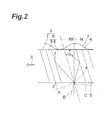
- the slant FOP 3 is formed so that, in a predetermined normal plane including an optical axis Rf of the optical fiber 6 and substantially perpendicular to the output end surface 5, an angle created by the optical axis Rf of the optical fiber 6 and the output end surface 5 is a predetermined slant angle ⁇ (first angle).
- the slant angle ⁇ is an angle less than 90°.
- the normal plane corresponds to the planes of sheets of Fig. 1 and Fig. 2 .
- the direction in which the optical axis Rf of the optical fiber 6 is inclined with respect to the output end surface 5 is shown by the arrow S of Fig. 2 .
- this direction is referred to as an optical axis inclination direction S.
- a finger 2 is placed so that its fingertip is pointed in the optical axis inclination direction S.
- an irradiation light source (irradiating means) 10 for irradiating the output end surface 5 with light and a CCD [Charge-Coupled Device] camera (relief pattern detecting means) 11 for detecting a fingerprint image based on light emitted from the output end surface 5 are disposed.
- the irradiation light source 10 As the irradiation light source 10, an incandescent lamp, a discharge lamp, an LED [Laser-Emitting Diode], an organic EL [Electro Luminescence] element, a laser, or the like is used.
- the irradiation light source 10 is disposed, on the side of the output end surface 5 of the slant FOP 3, in the optical axis inclination direction S when viewed from the slant FOP 3.
- the irradiation light source 10 is disposed so that, in the normal plane, an angle created by the direction in which light is irradiated and the output end surface 5 is a predetermined irradiation angle ⁇ (second angle).
- the irradiation angle ⁇ is an angle less than 90°.
- the CCD camera 11 is disposed directly below the slant FOP 3, and images the whole fingerprint of the finger 2 placed on the input end surface 4 from the front.
- the CCD camera 11 is disposed on a lower side further than the irradiation light source 10.
- the slant angle ⁇ of the slant FOP 3 and the irradiation angle ⁇ of the irradiation light source 10 are set so as to satisfy a cladding incident condition that light made incident into the core 8 of the optical fiber 6 from the output end surface 5 enters into the cladding 9 (refer to arrow A of Fig. 2 ).
- light with which the irradiation light source 10 irradiates the output end surface 5 does not serve as a main object of fiber transmission in the optical fiber 6.
- the relief pattern detection device 1 in the relief pattern detection device 1, light made incident into the core 8 from the output end surface 5 enters into the cladding 9 to be scattered without being totally reflected at an interface between the core 8 and the cladding 9. A part of the scattered light is absorbed in the absorber 7, and a part of light not absorbed in the absorber 7 travels inside the slant FOP 3 to reach the input end surface 4.
- the cladding incident condition is satisfied, in the slant FOP 3 having a thickness of 1mm, a fiber size of 6 ⁇ m, a numerical aperture of 1, a refractive index of the core 8 of 1.82, and a refractive index of the cladding 9 of 1.495, if the slant angle ⁇ is 68° and the irradiation angle ⁇ is an angle within a range of 24° to 90° from a normal N, and light enters into the cladding 9 to be scattered.
- the cladding incident condition is not satisfied, in the slant FOP 3 having a thickness of 1mm, a fiber size of 6 ⁇ m, a numerical aperture of 1, a refractive index of the core 8 of 1.82, and a refractive index of the cladding 9 of 1.495, when the slant angle ⁇ is 68° and the irradiation angle ⁇ is an angle of not less than 0° and not more than 24° from a normal N, and light travels inside the core 8.
- the arrow C of Fig. 2 shows that light in a direction parallel to the output end surface 5 irradiated from a side of the slant FOP 3 does not satisfy the cladding incident condition in some cases.
- a fingerprint being a relief pattern on the finger surface is expressed as the brightness and darkness of reflected light, so that the fingerprint can be detected as an image by the CCD camera 11.
- the relief pattern detection device According to the relief pattern detection device 1, light does not need to be transmitted through the finger 2 at the time of fingerprint detection, so that a decrease in image contrast under the influence of the thickness of the finger 2 can be avoided. Furthermore, because the light irradiated by the irradiation light source 10 satisfies the cladding incident condition, the brightness and darkness of reflected light according to the fingerprint relief is clearly expressed, thereby allowing detection of an image with sufficient contrast. Therefore, according to the relief pattern detection device 1, the reliability of relief pattern detection can be improved.
- the slant FOP 3 in the relief pattern detection device 1, because the slant FOP 3 is used, there is little influence of a smudge on the input end surface 4, and only a fingerprint M of a detection object can be accurately detected. Moreover, using the slant FOP 3 in place of a prism is advantageous in reducing the size and weight of the device.
- the image detectable range means a range in which a CCD camera can detect an image with sufficient contrast based on light emitted from an output end surface.
- a standard slant FOP 12 whose slant angle of 68° and a measurement slant FOP 13 having an arbitrary slant angle ⁇ are disposed side by side for the purpose of contrast comparison.
- a standard irradiation light source 14 with a fixed irradiation angle of 20° and a measurement irradiation light source 15 with an adjustable irradiation angle ⁇ are disposed on the output end surface side of the slant FOPs 12, 13 and in the optical axis inclination direction S when viewed from the slant FOPs 12, 13.
- the slant angle ⁇ of the measurement slant FOP 13 and the irradiation angle ⁇ of the measurement irradiation light source 15 were changed, and whether it was within the image detectable range, that is, whether an image with sufficient contrast was detectable was determined visually with reference to an image of reflected light of light of the standard irradiation light source 14 toward the standard slant FOP 12
- the standard irradiation light source 14 and the measurement irradiation light source 15 were adjusted so that light to be irradiated approximates parallel light. Specifically, adjustment was performed so that the diameter of irradiation light takes a diameter of 20mm in direct proximity to the irradiation light source, a diameter of 15mm at a position 70mm away from the irradiation light source, and a diameter of 20mm at a position 100mm away from the irradiation light source.
- the standard irradiation light source 14 irradiated a range across a boundary line between the standard slant FOP 12 and the measurement slant FOP 13 with light, and its irradiation center T1 was located on the boundary line.
- the distance between the standard irradiation light source 14 and the irradiation center T1 was provided as 80mm.
- the measurement irradiation light source 15 irradiated a range across a boundary line between the standard slant FOP 12 and the measurement slant FOP 13 with light, and its irradiation center T2 was located on the boundary line.
- the distance between the measurement irradiation light source 15 and the irradiation center T2 was provided as 80mm.
- the range was changed with the irradiation angle ⁇ of the measurement irradiation light source 15 fixed at 20°, and the illumination intensity of its irradiation light and reflected light was measured by use of an illuminometer.
- the measurement results are shown in Table 1. Based on the measurement results, the range was set to 7 with regard to the illumination intensity of the measurement irradiation light source 15 during measurement. Similarly, the range was set to 7 also for the standard irradiation light source 14.
- the image detectable range being a measurement object is expressed schematically as a range extending in a substantially elliptic cone shape having an apex at the irradiation center T2.
- the image detectable range is expressed by three angles ⁇ f, ⁇ b, ⁇ w having an apex at the irradiation center T2 and having a reference (0°) at the output end surface.
- ⁇ f is an angle around the irradiation center T2 in a plane (hereinafter, referred to as "a normal plane") including a normal of the output end surface and an optical axis of the measurement irradiation light source 15.
- ⁇ f is an angle until an image with sufficient contrast becomes detectable when the CCD camera (not shown) being an observation point is moved in an arc shape, with the output end surface on the side of the measurement irradiation light source 15 provided as 0°.
- ⁇ b is an angle around the irradiation center T2 in the normal plane. ⁇ b is an angle until an image with sufficient contrast can no longer be detected when the CCD camera is moved toward the output end surface on the opposite side to the measurement irradiation light source 15.
- an average angle of ⁇ f and ⁇ b is expressed as a central angle ⁇ c, and a segment that creates the central angle ⁇ c with the output end surface is expressed by W.
- ⁇ w is an angle around the irradiation center T2 in a central angle plane which is a plane including the segment W and vertical to the normal plane. ⁇ w is an angle until an image with sufficient contrast becomes detectable when the CCD camera is moved in an arc shape in the central angle plane, with the output end surface provided as 0°. ⁇ w takes the same value on the left and right when viewed from the measurement irradiation light source 15.
- the image detectable range can be expressed by use of ⁇ f, ⁇ b, ⁇ w described in the above. Specifically, a range of ⁇ f to ⁇ b in the normal plane and a range of ⁇ w to 180- ⁇ w in the central angle plane correspond to the image detectable range.
- ⁇ a is an angular width in the normal plane of the image detectable range, and is expressed as a difference of ⁇ f and ⁇ b.
- Table 2 to Table 4 show relationships between the irradiation angle ⁇ of the measurement irradiation light source 15 and the slant angle ⁇ of the measurement slant FOP 13 and ⁇ f, ⁇ b, and ⁇ w.
- Table 2 is a table showing a relationship between the slant angle ⁇ and ⁇ f, ⁇ b, and ⁇ w when the irradiation angle ⁇ is 10°.
- Table 3 is a table showing a relationship between the slant angle ⁇ and ⁇ f, ⁇ b, and ⁇ w when the irradiation angle ⁇ is 20°.
- Table 4 is a table showing a relationship between the slant angle ⁇ and ⁇ f, ⁇ b, and ⁇ w when the irradiation angle ⁇ is 30°.
- Table 2 IRRADIATIO N ANGLE SLANT ANGLE ⁇ ⁇ f ⁇ b ⁇ c ANGULAR WIDTH ⁇ a IRRADIATION ANGLE SLANT ANGLE ⁇ ⁇ w 10° 78 50 75 62.5 25 10.
- Table 3 IRRADIATIO N ANGLE SLANT ANGLE ⁇ ⁇ f ⁇ b ⁇ c ANGULAR WIDTH ⁇ a IRRADIATION ANGLE SLANT ANGLE ⁇ ⁇ w 20° 78 50 70 60.0 20 20° 78 45 73 60 95 77.5 35 73 45 68 70
- Fig. 6 is a graph showing the relationship between the slant angle ⁇ and ⁇ f and ⁇ b when the irradiation angle is 20° shown in Table 3
- Fig. 7 is a view showing the relationship between the slant angle ⁇ and ⁇ f and ⁇ b when the irradiation angle is 20°
- Fig. 8 is a graph showing the relationship between the slant angle ⁇ and ⁇ f and ⁇ b when the irradiation angle is 30° shown in Table 4.
- the image detectable range expressed by ⁇ f and ⁇ b inclined to the irradiation light source side as the slant angle ⁇ increased, and the image detectable range inclined to the side opposite to the irradiation light source as the slant angle ⁇ decreased.
- the irradiation angle was 10° or 20°, the smaller the slant angle ⁇ , the larger the angular width ⁇ a, that is, the image detectable range.
- the contrast of the irradiation center T2 shown in Fig. 5(a) to Fig. 5(c) was measured visually by changing the slant angle ⁇ and the irradiation angle ⁇ .
- the measurement conditions are different from those for the image detectable range described above mainly in that the CCD camera (not shown) being an observation point was fixed in position, and the range of the irradiation light source was changed for measurement.
- the CCD camera was fixed to a position directly below a boundary line between the standard slant FOP 12 and the measurement slant FOP 13 and where the irradiation centers T1, T2 could be imaged.
- Table 5 is a table showing visual contrast grading. As shown in Fig. 5 , the contrast of each image of the irradiation center T2 imaged by the CCD camera was graded at a 5-point scale. Here, the grading was performed by rating the contrast when the slant angle ⁇ was 68° and the irradiation angle ⁇ was 10° at grade 5. In addition, the image detectable range described above corresponds to a range having a contrast of grade 4 or more in Table 5. [Table 5] GRADE 5 HAS STRONG CONTRAST 4 HAS CONTRAST 3 HAS SOME CONTRAST 2 FINGER COLOR BEGINS TO APPEAR TO DEGRADE CONTRAST. 1 HAS NO CONTRAST. NO FINGERPRINT OBSERVED.
- Table 6 to Table 8 show relationships between the slant angle ⁇ and the irradiation angle ⁇ and the contrast of the irradiation center T2.
- Table 6 is a table showing a relationship between the slant angle ⁇ and the irradiation angle ⁇ and the contrast of the irradiation center T2 when the range of the measurement irradiation light source 15 is 7.
- Table 7 is a table showing a relationship between the slant angle ⁇ and the irradiation angle ⁇ and the contrast of the irradiation center T2 when the range of the measurement irradiation light source 15 is 9.
- Table 8 is a table showing a relationship between the slant angle ⁇ and the irradiation angle ⁇ and the contrast of the irradiation center T2 when the range of the measurement irradiation light source 15 is 6.
- Fig. 9 is a graph showing the relationship between the slant angle ⁇ and the irradiation angle ⁇ and the contrast of the irradiation center T2 of Table 6.
- the slant angle ⁇ of the slant FOP was 63° to 73° and the irradiation angle ⁇ of the irradiation light source was 5° to 30°.
- the slant angle ⁇ is 68° and the irradiation angle ⁇ is 5° to 30°.
- the image detectable range in this case is ⁇ f of 70°, ⁇ b of 105°, and ⁇ a of 35°, and has ⁇ w of approximately 45°, and is thus suitable for observation from the side. Therefore, when the slant angle ⁇ is 68° and the irradiation angle ⁇ is 5° to 30°, it is considered satisfactory that the angle created by the observation direction and the output end surface 5 is up to approximately 45°.
- a relief pattern detection device 21 according to a second embodiment is different from the relief pattern detection device 1 according to the first embodiment in including a reinforcing member.
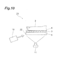
- the relief pattern detection device 21 includes a thick plate-shaped reinforcing member 22 disposed on the output end surface 5 of the slant FOP 3.
- the reinforcing member 22 is made of an acrylic resin, glass, or the like, and transmits light of the irradiation light source 10 and reflected light reflected on the input end surface 4 and emitted from the output end surface 5.
- the device durability can be improved by reinforcing the slant FOP 3 by the reinforcing member 22. Furthermore, by disposing on the side of the output end surface 5 of the slant FOP 3 the reinforcing member 22 that transmits light of the irradiation light source 10 and reflected light, the influence on the accuracy of fingerprint detection can be suppressed to the minimum. Moreover, an improvement in durability can be realized with a simple structure, which is thus advantageous in reducing the cost of the device.
- a relief pattern detection device 31 according to a third embodiment is different from the relief pattern detection device 1 according to the first embodiment in detecting a hand palmprint and the shape of the slant FOP.
- the relief pattern detection device 31 is for detecting a palmprint of a left hand 32 of a detection object person, and includes a slant FOP 33 having at its upper surface an input end surface (first surface) 34 which makes contact with the hand 32.
- the slant FOP 33 is formed in a tile shape by a front portion 33a curved in a projecting shape and a rear portion 33b curved in a recessed shape.
- An upper surface (first curved surface) 34a of the front portion 33a shows a projecting curved surface when viewed in a direction parallel to a predetermined normal plane (corresponding to the plane of a sheet of Fig. 14 ) including the optical axis Rf of the optical fiber 6 and substantially perpendicular to an output end surface 35.
- the upper surface 34a of the front portion 33a shows a moderately projecting curved surface along the palm.
- an upper surface 34b of the rear portion 33b shows a recessed curved surface when viewed in the direction parallel to the normal plane.
- the upper surface 34b of the rear portion 33b shows a recessed curved surface along a wrist portion of the palm.
- the hand 32 is placed so that the wrist portion of the palm makes contact with the upper surface 34b of the rear portion 33b and other parts make contact with the upper surface 34a of the front portion 33a.
- the upper surface 34a of the front portion 33a of the slant FOP 33 makes it easy to bring the palm into close contact with the input end surface 34, so that the accuracy of palmprint detection can be improved.
- the slant FOP 33 is formed so that the optical axes Rf of optical fibers that form the slant FOP 33 are inclined toward a thumb side in a width direction of the hand 32. That is, the optical axis inclination direction S of the slant FOP 33 corresponds to a direction from the pinky side toward the thumb side of the width direction of the hand 32.
- the optical axis Rf of the optical fiber is coincident with a normal N of the output end surface 35.
- the slant FOP 33 is formed at its lower surface with an output end surface (second surface) 35.
- the slant FOP 33 has a constant thickness, and the input end surface 34 and the output end surface 35 of the slant FOP 33 are formed so as to have a constant interval therebetween.
- the CCD camera 11 is disposed directly below the front portion 33a of the slant FOP 33 and within an image detectable range in which the CCD 11 camera can detect the palmprint of the hand 32 as an image with sufficient contrast.
- Figs. 15 and 16 show angular widths ⁇ a, ⁇ b of image detectable ranges.
- ⁇ b is the angular width of an image detectable range in a central angle plane, and its value is equal to 180° from which a value of two times ⁇ w has been subtracted.
- the CCD camera 11 images the whole palm of the hand 32 placed on the input end surface 34 from the front.
- the same effects as those of the relief pattern detection device 1 according to the first embodiment can be obtained.
- light does not need to be transmitted through the hand 32 at the time of palm detection, so that a decrease in image contrast under the influence of the thickness of the hand 32 that varies more from person to person than a finger can be avoided to obtain an image with substantially uniform illumination.
- using the slant FOP 33 in place of a prism makes it easy to increase the input end surface 34 in area, and forming the slant FOP 33 in a tile shape allows a reduction in the size of the device while sufficiently securing the area of the input end surface 34.
- the relief pattern detection device 31 having such a configuration can be suitably used also for collectively detecting fingerprints of four fingers, besides palmprint detection.
- a relief pattern detection device 41 according to a fourth embodiment is different from the relief pattern detection device 31 according to the third embodiment in including a reinforcing member.
- the relief pattern detection device 41 includes a thick-plate reinforcing member 42 formed in a wave shape along the output end surface 35 of the slant FOP 33.
- An upper surface of the reinforcing member 42 is adhered to the output end surface 35 of the slant FOP 33.
- the reinforcing member 42 is made of an acrylic resin, glass, or the like, and transmits light of the irradiation light source 10 and reflected light reflected on the input end surface 34 and emitted from the output end surface 35.
- the slant FOP 33 can be reinforced by the reinforcing member 42, so that the device durability can be improved. Furthermore, by disposing on the side of the output end surface 35 of the slant FOP 33 the reinforcing member 42 that transmits light of the irradiation light source 10 and reflected light, the influence on the accuracy of fingerprint detection can be suppressed to the minimum. Moreover, an improvement in durability can be realized with a simple structure, which is thus advantageous in reducing the cost of the device.
- a relief pattern detection device 51 according to a fifth embodiment is different from the relief pattern detection device 41 according to the fourth embodiment in only the shape of the reinforcing member.
- the relief pattern detection device 51 includes a mount-shaped reinforcing member 52 on which the tile-shaped slant FOP 33 is mounted.
- An upper surface of the reinforcing member 52 is formed in a wave shape along the output end surface 35 of the slant FOP 33, and is adhered without a gap to the output end surface 35 of the slant FOP 33.
- the reinforcing member 52 is made of an acrylic resin, glass, or the like, and transmits light of the irradiation light source 10 and reflected light reflected on the input end surface 34 and emitted from the output end surface 35.
- the same effects as those of the relief pattern detection device 41 according to the fourth embodiment can be obtained. Furthermore, forming the reinforcing member 52 in a mount shape allows an improvement in the assemblability of the reinforcing member 52 and the slant FOP 33 onto another member.
- a relief pattern detection device 61 according to a sixth embodiment is different from the relief pattern detection device 1 according to the first embodiment in being capable of detecting a rotated fingerprint, the shape of the slant FOP, the disposition and number of irradiation light sources, and the disposition of the CCD camera.
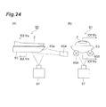
- the relief pattern detection device 61 is for detecting a rotated fingerprint of a finger 2 of a detection object person, and includes a slant FOP 63 having at its upper surface an input end surface (first surface, second curved surface) 64 with which the finger 2 makes contact.
- the slant FOP 63 shows a substantially half-pipe shape.
- the slant FOP 63 is formed so as to curve up to the left and right from directly under the finger 2.
- a front end portion 63a of the slant FOP 63 is continuous so as to show a U-shape when viewed from above, and a fingertip strikes against its inner surface.
- the input end surface 64 of the slant FOP 63 shows a recessed curved surface when viewed in a direction parallel to a predetermined normal plane (corresponding to the plane of a sheet of Fig. 25(b) ) including the optical axis Rf of the optical fiber 6 and substantially perpendicular to an output end surface 35.
- the input end surface 64 shows a recessed curved surface so as to extend along a lower-side surface of the finger 2.
- the slant FOP 63 is formed at its lower surface with an output end surface (second surface) 65.
- the slant FOP 63 has a constant thickness, and the input end surface 64 and the output end surface 65 of the slant FOP 63 are formed so as to have a constant interval therebetween.
- the slant FOP 63 is formed so that the optical axes of optical fibers that form the slant FOP 63 are inclined in a direction in which the fingertip is pointed except at the front end portion 63a. That is, the optical axis inclination direction S of the slant FOP 63 corresponds to a direction in which the fingertip of the finger 2 is pointed except at the front end portion 63a. In addition, at the front end portion 63a, the optical axis inclination direction S takes a direction inclined upward to match the slant FOP 63 that is inclined upward along the fingertip surface.
- the optical axis of the optical fiber is coincident with a normal N of the output end surface 65.
- irradiation light sources 66A, 66B that irradiate light from the left and right toward the surface of the lower side of the finger 2.
- the irradiation light sources 66A, 66B are disposed, on the side of the output end surface 65 of the slant FOP 63, side by side in the direction in which the fingertip is pointed.
- the irradiation light sources 66A, 66B are disposed at positions such that irradiated light is made incident into the output end surface 65 in a direction where the irradiated light does not serve as a main object of fiber transmission in the slant FOP 63.
- a CCD camera 67 for detecting reflected light emitted from the output end surface 65 of the slant FOP 63.
- the CCD camera 67 is disposed further below than the irradiation light sources 66A, 66B.
- the CCD camera 67 is disposed at a position where it can detect a fingerprint image, that is, within an image detectable range.
- Fig. 26 shows examples of angular widths ⁇ a, ⁇ b of image detectable ranges.
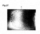
- a rotated fingerprint can be detected without rotating the finger 2 (refer to Fig. 27 ). Further, because detection of a rotated fingerprint is realized with a simple configuration, a reduction in the size of the device is easy.
- image brightness can be uniformized by including the plurality of irradiation light sources 66A, 66B.
- the number of irradiation light sources is not limited to two, and three or more irradiation light sources may be included.
- a relief pattern detection device 71 according to a seventh embodiment is different from the relief pattern detection device 61 according to the sixth embodiment in including a reinforcing member and the numbers of irradiation light sources and CCD cameras.
- the relief pattern detection device 71 includes a block-shaped reinforcing member 72 on which a half pipe-shaped slant FOP 63 is mounted. A part of an upper surface of the reinforcing member 72 is depressed in the form of the output end surface 65 of the slant FOP 63, and the slant FOP 63 is fitted in the depression while the output end surface 65 of the slant FOP 63 and the upper surface of the reinforcing member 72 are adhered to each other without a gap.
- the reinforcing member 72 is made of an acrylic resin, glass, or the like, and transmits light of the irradiation light sources 76A to 76D and reflected light reflected on the input end surface 64 and emitted from the output end surface 65.
- the irradiation light sources 76A to 76D are disposed, on the side of the output end surface 65 of the slant FOP 63 (outside the reinforcing member 72), in the direction in which the fingertip of the finger 2 is pointed.
- the irradiation light sources 76A, 76B are disposed obliquely above the slant FOP 63, and irradiate light from the left and right toward the lower side of the fingertip of the finger 2 through the front end portion 63a of the slant FOP 63 that is inclined upward.
- the irradiation light sources 76C, 76D are disposed obliquely below the slant FOP 63, and irradiate light from the left and right toward the lower side of a cushion of the finger 2 through the slant FOP 63.
- a CCD camera 77C for detecting a fingertip image of the finger 2 is disposed on the lower side of the slant FOP 63.
- a CCD camera (not shown) to be paired with the CCD camera 77C is disposed.
- the slant FOP 63 can be reinforced by the reinforcing member 72, so that the device durability can be improved. Furthermore, by disposing on the side of the output end surface 65 of the slant FOP 63 the reinforcing member 72 that transmits light of the irradiation light sources 76A, 76B and reflected light, the influence on the accuracy of fingerprint detection can be suppressed to the minimum. Moreover, an improvement in durability can be realized with a simple structure, which is thus advantageous in reducing the cost of the device.
- image detection of a rotated fingerprint without dead angles is realized by including a plurality of CCD cameras and combining images detected by the respective cameras.
- a relief pattern detection device 81 according to an eighth embodiment is different from the relief pattern detection device 71 according to the seventh embodiment in only the shape of the reinforcing member.
- the relief pattern detection device 81 includes a thick-plate reinforcing member 82 having at its upper surface a recess extending along the output end surface 65 of the slant FOP 63.
- the recess of the upper surface of the reinforcing member 82 and the output end surface 65 of the slant FOP 63 are adhered to each other without a gap.
- the reinforcing member 82 is made of an acrylic resin, glass, or the like, and transmits light of the irradiation light sources 76A to 76D and reflected light reflected on the input end surface 64 and emitted from the output end surface 65.
- the relief pattern detection device 81 according to the eighth embodiment thus configured, the same effects as those of the relief pattern detection device 71 according to the seventh embodiment can be obtained. Furthermore, the reinforcing member 82 is formed in a thick plate shape, which is thus advantageous in reducing the thickness of the device.
- the present invention is not limited to the embodiments described above.
- the relief pattern detection device can be suitably used also for detection of a relief pattern on the surface of a soft object such as a rubber stamp, besides detection of a fingerprint and a palmprint.
- the shape of the slant FOP 3 is not limited to the shapes described above, and even a slant FOP for palmprint detection may be formed in a flat plate shape.
- the disposition of the irradiation light source and CCD camera is appropriately set according to the shape and the like of the slant FOP 3.
- the reinforcing member is not limited to ones in a thick plate shape, a mount shape, or a block shape, and variously shaped members may be used.
- the reinforcing member may be provided in a shape that allows usage of the reinforcing member as a connection member with another component.
Landscapes
- Engineering & Computer Science (AREA)
- Physics & Mathematics (AREA)
- General Physics & Mathematics (AREA)
- Theoretical Computer Science (AREA)
- Human Computer Interaction (AREA)
- Multimedia (AREA)
- Image Input (AREA)
- Optical Fibers, Optical Fiber Cores, And Optical Fiber Bundles (AREA)
- Measurement Of The Respiration, Hearing Ability, Form, And Blood Characteristics Of Living Organisms (AREA)
Abstract
Description
- The present invention relates to a relief pattern detection device.
- Conventionally, as devices for detecting relief patterns on the surfaces of objects, ones using prisms are known (refer to, for example,
Patent Documents 1 and 2). A fingerprint pattern input device described inPatent Document 1 includes a triangular prism having at its upper surface a finger contact surface with which a finger is brought into contact, a light source disposed obliquely below the prism, for irradiating light toward the finger contact surface of the prism, and a camera for detecting a fingerprint image from reflected light reflected on the finger contact surface of the prism. - However, in the fingerprint pattern input device described above, because the finger contact surface of the prism is obliquely irradiated with light and reflected light thereof is also emitted in an oblique direction of the finger contact surface, a detected fingerprint image is of a fingerprint viewed obliquely, and there has been a problem that the image is distorted as compared to when viewed from the front. Therefore, devices using fiber optic plates in place of prisms in order to solve such problems are known (refer to, for example,
Patent Documents 3 to 7). - A fingerprint detection device described in
Patent Document 3 includes a fiber optic plate having an input end surface on which a finger is placed and an output end surface parallel to the input end surface, a light source disposed on the input end surface side, for irradiating light toward a finger, and a CCD camera disposed on the output end surface side, for imaging a fingerprint from light transmitted through the finger. In the fingerprint detection device, an image of a fingerprint viewed from the front can be obtained by imaging a fingerprint using light transmitted through a finger. - Patent Document 1: Japanese Patent Application Laid-Open No.
S62-212892
Patent Document 2: Japanese Patent Application Laid-Open No.S55-13446
Patent Document 3: Japanese Patent No.3461591
Patent Document 4: Japanese Patent Application Laid-Open No.H07-171137
Patent Document 5: United States Patent No.4,932,776
Patent Document 6: United States Patent No.4,785,171
Patent Document 7: Japanese Patent Application Laid-Open No.H06-300930 - However, in the fingerprint detection device of
Patent Document 3 described above, when this is used for detection of a relief pattern on the surface of a thick object such as a hand palmprint, the image contrast decreases according to the object thickness because light needs to be transmitted through the object. Therefore, detection results may be subject to variation caused by the influence of object thickness, and the reliability of relief pattern detection may be reduced accordingly. - Therefore, the present invention has been made in view of the problems described above, and it is an object to provide a highly reliable relief pattern detection device.
- The present invention is a relief pattern detection device for detecting a relief pattern on an object surface including a fiber optic plate having a first surface which is formed of first end faces of a plurality of optical fibers and with which the object surface is brought into contact and a second surface which is formed of second end faces of the optical fibers and is substantially parallel to the first surface, an irradiating means disposed on the second surface side of the fiber optic plate, for irradiating the second surface with light, and a relief pattern detecting means disposed on the second surface side of the fiber optic plate, for detecting the relief pattern based on light emitted from the second surface, in which optical axes of the optical fibers are inclined so as to create a first angle less than 90° in one direction from the second surface within a predetermined plane substantially perpendicular to the second surface, the irradiating means irradiates the second surface with light in a direction to create a second angle less than 90° in the other direction from the second surface within the predetermined plane, and the first angle and the second angle are set so that light made incident from the second surface into a core of the optical fiber enters into a cladding of the optical fiber.
- In the relief pattern detection device according to the present invention, when the irradiating means irradiates the second surface with light, the light is propagated from the second surface toward the first surface, the light is scattered or absorbed at projections on the object surface that are in contact with the first surface, and the light is reflected by the first surface at recesses that are out of contact with the first surface. Accordingly, a relief pattern on the object surface is expressed as the brightness and darkness of reflected light, so that the relief pattern can be detected as an image. Therefore, according to the relief pattern detection device, light does not need to be transmitted through the object, so that a decrease in image contrast under the influence of the thickness of the object can be avoided. An image with sufficient contrast can thereby be obtained, so that the reliability of relief pattern detection can be improved.
- In the relief pattern detection device according to the present invention, it is preferable that the first angle is an angle within a range of 63° to 73°, and the second angle is an angle within 5° to 30°.
- In the relief pattern detection device according to the present invention, it is preferable that, on the second surface of the fiber optic plate, a reinforcing member that transmits the light of the irradiating means is provided. In this case, because the fiber optic plate can be reinforced by the reinforcing member, the life of the device can be extended. Furthermore, by disposing on the second surface side of the fiber optic plate the reinforcing member that transmits light of the irradiating means and reflected light, the influence on the accuracy of relief pattern detection can be suppressed to the minimum. Moreover, an improvement in durability can be realized with a simple structure, which is thus advantageous in reducing the cost of the device.
- In the relief pattern detection device according to the present invention, it is preferable that the first surface of the fiber optic plate has a first curved surface to show a projecting shape when viewed in a direction substantially parallel to the predetermined plane. By forming the first curved surface along the object surface, for example, a palm, the object surface can be easily brought into close contact with the first surface at the time of relief pattern detection, so that the accuracy of detection can be improved.
- In the relief pattern detection device according to the present invention, it is preferable that the first surface of the fiber optic plate has a second curved surface to show a recessed shape when viewed in a direction substantially parallel to the predetermined plane. By forming the first curved surface along the object surface, for example, the surface of a finger, the object surface can be easily brought into close contact with the first surface at the time of relief pattern detection, so that the accuracy of detection can be improved.
- According to the present invention, a highly reliable relief pattern detection device can be provided.
-
- [
Fig. 1 ] A schematic side view showing a first embodiment of a relief pattern detection device by the present invention. - [
Fig. 2 ] An enlarged sectional view showing a slant FOP ofFig. 1 . - [
Fig. 3 ] A view showing fingerprints detected by a conventional prismatic relief pattern detection device. - [
Fig. 4 ] A view showing a fingerprint detected by the relief pattern detection device ofFig. 1 . - [
Fig. 5] Fig. 5(a) is a side view showing a measurement status of an image detectable range.Fig. 5(b) is a front view showing a measurement status of an image detectable range.Fig. 5(c) is a bottom view showing a measurement status of an image detectable range. - [
Fig. 6 ] A graph showing a relationship between the angle of the image detectable range and the slant angle when the irradiation angle is 20°. - [
Fig. 7 ] A view showing a relationship between the angle of the image detectable range and the slant angle when the irradiation angle is 20°. - [
Fig. 8 ] A graph showing a relationship between the angle of the image detectable range and the slant angle when the irradiation angle is 30°. - [
Fig. 9 ] A graph showing a relationship between the contrast of an irradiation center and the irradiation angle and slant angle. - [
Fig. 10 ] A schematic side view showing a relief pattern detection device according to a second embodiment. - [
Fig. 11 ] A schematic side view showing a relief pattern detection device according to a third embodiment. - [
Fig. 12 ] A schematic bottom view showing the relief pattern detection device ofFig. 11 . - [
Fig. 13 ] A schematic front view showing the relief pattern detection device ofFig. 11 . - [
Fig. 14 ] A sectional view taken along a line XIV-XIV ofFig. 11 . - [
Fig. 15 ] A schematic side view for explaining an image detectable range in the relief pattern detection device ofFig. 11 . - [
Fig. 16 ] A sectional view for explaining an image detectable range in the relief pattern detection device ofFig. 11 . - [
Fig. 17 ] A photo of a palmprint detected by the relief pattern detection device ofFig. 11 . - [
Fig. 18 ] A schematic side view showing a relief pattern detection device according to a fourth embodiment. - [
Fig. 19 ] A schematic bottom view showing the relief pattern detection device ofFig. 18 . - [
Fig. 20 ] A schematic front view showing the relief pattern detection device ofFig. 18 . - [
Fig. 21 ] A schematic side view showing a relief pattern detection device according to a fifth embodiment. - [
Fig. 22 ] A schematic bottom view showing the relief pattern detection device ofFig. 21 . - [
Fig. 23 ] A schematic front view showing the relief pattern detection device ofFig. 21 . - [
Fig. 24] Fig. 24(a) is a schematic side view showing a relief pattern detection device according to a sixth embodiment.Fig. 24(b) is a schematic front view showing the relief pattern detection device ofFig. 24(a) . - [
Fig. 25] Fig. 25(a) is a sectional view taken along a line XXIVa-XXIVa ofFig. 24(a) .Fig. 25(b) is a sectional view taken along a line XXIVb-XXIVb ofFig. 24(b) . - [
Fig. 26] Fig. 26(a) is a sectional view corresponding toFig. 25(a) for explaining an angular width of an image detectable range.Fig. 26(b) is a sectional view corresponding toFig. 25(b) for explaining an angular width of an image detectable range. - [
Fig. 27 ] A view showing a rotated fingerprint detected by the relief pattern detection device ofFig. 24 . - [
Fig. 28] Fig. 28(a) is a sectional view corresponding toFig. 25(a) showing a relief pattern detection device according to a seventh embodiment.Fig. 28(b) is a sectional view corresponding toFig. 25(b) showing the relief pattern detection device ofFig. 28(a) . - [
Fig. 29] Fig. 29(a) is a sectional view corresponding toFig. 24(a) showing a relief pattern detection device according to an eighth embodiment.Fig. 29(b) is a sectional view corresponding toFig. 24(b) showing the relief pattern detection device ofFig. 29(a) . - Hereinafter, preferred embodiments of the present invention will be described in detail with reference to the drawings. Also, the same or corresponding parts will be denoted with the same reference signs in the drawings, and overlapping description will be omitted.
- As shown in
Fig. 1 andFig. 2 , a reliefpattern detection device 1 according to the present embodiment is for detecting a fingerprint that is a relief pattern on the surface of a finger, and includes a slant fiber optic plate (hereinafter, referred to as a slant FOP) 3 having at its upper surface an input end surface (first surface) 4 which makes contact with afinger 2. - The
slant FOP 3 is a type of so-called fiber optic plate (Fiber Optic Plate, FOP) for which a plurality of bundled and unitedoptical fibers 6 are formed into a plate shape. The fiber optic plate is an optical element for which, for example, several tens of millions of several-micrometer-diameter single fibers are bundled and fusion-bonded (for example, by heating and pressing). The single fiber is generally formed of three types of glass of a core glass that transmits light, a cladding glass that covers the core glass, and an absorber (E.M.A.) glass that absorbs light leaked from the core glass. The single fiber transmits light as a result of total reflection caused at a boundary between the core glass and cladding glass due to a difference in refractive index therebetween. Light made incident at an angle of the maximum light receiving angle or more is released outside the fiber without causing total reflection, but is absorbed by the absorber glass disposed around the cladding glass. An optical image can therefore be transmitted without a reduction in resolution. - The
slant FOP 3 is formed of a plurality ofoptical fibers 6 and anabsorber 7 for absorbing light leaked from theoptical fiber 6, disposed between theoptical fibers 6. Moreover, theoptical fiber 6 is formed of acore 8 and a cladding 9 surrounding thecore 8. - The
slant FOP 3 has aninput end surface 4 formed of upper end faces (first end faces) of theoptical fibers 6 and an output end surface (second surface) 5 formed of lower end faces (second end faces) of theoptical fibers 6. Theslant FOP 3 is formed so as to have a constant thickness, and theinput end surface 4 and theoutput end surface 5 are parallel to each other. - Moreover, the
slant FOP 3 is formed so that, in a predetermined normal plane including an optical axis Rf of theoptical fiber 6 and substantially perpendicular to theoutput end surface 5, an angle created by the optical axis Rf of theoptical fiber 6 and theoutput end surface 5 is a predetermined slant angle α (first angle). The slant angle α is an angle less than 90°. The normal plane corresponds to the planes of sheets ofFig. 1 andFig. 2 . - Here, the direction in which the optical axis Rf of the
optical fiber 6 is inclined with respect to theoutput end surface 5 is shown by the arrow S ofFig. 2 . In the following, this direction is referred to as an optical axis inclination direction S. On theinput end surface 4 of theslant FOP 3, afinger 2 is placed so that its fingertip is pointed in the optical axis inclination direction S. - On the side of the
output end surface 5 of theslant FOP 3, an irradiation light source (irradiating means) 10 for irradiating theoutput end surface 5 with light and a CCD [Charge-Coupled Device] camera (relief pattern detecting means) 11 for detecting a fingerprint image based on light emitted from theoutput end surface 5 are disposed. - As the
irradiation light source 10, an incandescent lamp, a discharge lamp, an LED [Laser-Emitting Diode], an organic EL [Electro Luminescence] element, a laser, or the like is used. Theirradiation light source 10 is disposed, on the side of theoutput end surface 5 of theslant FOP 3, in the optical axis inclination direction S when viewed from theslant FOP 3. Theirradiation light source 10 is disposed so that, in the normal plane, an angle created by the direction in which light is irradiated and theoutput end surface 5 is a predetermined irradiation angle β (second angle). The irradiation angle β is an angle less than 90°. - The
CCD camera 11 is disposed directly below theslant FOP 3, and images the whole fingerprint of thefinger 2 placed on theinput end surface 4 from the front. TheCCD camera 11 is disposed on a lower side further than theirradiation light source 10. - Next, description will be given of a relationship between the slant angle α of the
slant FOP 3 and the irradiation angle β of theirradiation light source 10 in the reliefpattern detection device 1. - In the relief
pattern detection device 1, the slant angle α of theslant FOP 3 and the irradiation angle β of theirradiation light source 10 are set so as to satisfy a cladding incident condition that light made incident into thecore 8 of theoptical fiber 6 from theoutput end surface 5 enters into the cladding 9 (refer to arrow A ofFig. 2 ). In the reliefpattern detection device 1 with such a setting, light with which theirradiation light source 10 irradiates theoutput end surface 5 does not serve as a main object of fiber transmission in theoptical fiber 6. That is, in the reliefpattern detection device 1, light made incident into thecore 8 from theoutput end surface 5 enters into the cladding 9 to be scattered without being totally reflected at an interface between thecore 8 and the cladding 9. A part of the scattered light is absorbed in theabsorber 7, and a part of light not absorbed in theabsorber 7 travels inside theslant FOP 3 to reach theinput end surface 4. - Specifically, the cladding incident condition is satisfied, in the
slant FOP 3 having a thickness of 1mm, a fiber size of 6µm, a numerical aperture of 1, a refractive index of thecore 8 of 1.82, and a refractive index of the cladding 9 of 1.495, if the slant angle α is 68° and the irradiation angle β is an angle within a range of 24° to 90° from a normal N, and light enters into the cladding 9 to be scattered. - On the other hand, when the slant angle α and the irradiation angle β do not satisfy the cladding incident condition, light with which the
irradiation light source 10 has irradiated theoutput end surface 5 serves as a main object of fiber transmission in theoptical fiber 6. That is, light made incident by theirradiation light source 10 into thecore 8 from theoutput end surface 5 is totally reflected at the interface between thecore 8 and the clad 9 of theoptical fiber 6, and travels inside thecore 8 to be transmitted to the input end surface 4 (refer to arrow B ofFig. 2 ). - Specifically, the cladding incident condition is not satisfied, in the
slant FOP 3 having a thickness of 1mm, a fiber size of 6µm, a numerical aperture of 1, a refractive index of thecore 8 of 1.82, and a refractive index of the cladding 9 of 1.495, when the slant angle α is 68° and the irradiation angle β is an angle of not less than 0° and not more than 24° from a normal N, and light travels inside thecore 8. In addition, the arrow C ofFig. 2 shows that light in a direction parallel to theoutput end surface 5 irradiated from a side of theslant FOP 3 does not satisfy the cladding incident condition in some cases. - In the relief
pattern detection device 1 having the above configuration, when light irradiated by theirradiation light source 10 is made incident from theoutput end surface 5 to reach theinput end surface 4, the light is scattered or absorbed into thefinger 2 at projections on the finger surface that are in contact with theinput end surface 4, and the light is reflected by theinput end surface 4 at recesses that are out of contact with theinput end surface 4. Accordingly, a fingerprint being a relief pattern on the finger surface is expressed as the brightness and darkness of reflected light, so that the fingerprint can be detected as an image by theCCD camera 11. Thus, according to the reliefpattern detection device 1, light does not need to be transmitted through thefinger 2 at the time of fingerprint detection, so that a decrease in image contrast under the influence of the thickness of thefinger 2 can be avoided. Furthermore, because the light irradiated by theirradiation light source 10 satisfies the cladding incident condition, the brightness and darkness of reflected light according to the fingerprint relief is clearly expressed, thereby allowing detection of an image with sufficient contrast. Therefore, according to the reliefpattern detection device 1, the reliability of relief pattern detection can be improved. - Moreover, according to the relief
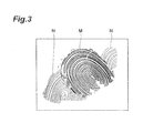
pattern detection device 1, because theslant FOP 3 is used in place of a prism, a reduction in the accuracy of fingerprint detection can be prevented even when there is a smudge such as oil from a finger on theinput end surface 4. That is, as shown inFig. 3 , in a method for fingerprinting by pressing a finger against a prism, because of fingerprint detection using a change in a total reflection condition caused by moisture from a finger, remaining fingerprints N are detected besides a fingerprint M of a detection object under the influence of oil from a finger and the like left on theinput end surface 4. On the other hand, as shown inFig. 4 , in the reliefpattern detection device 1, because theslant FOP 3 is used, there is little influence of a smudge on theinput end surface 4, and only a fingerprint M of a detection object can be accurately detected. Moreover, using theslant FOP 3 in place of a prism is advantageous in reducing the size and weight of the device. - Here, the relationship between the slant angle α and the irradiation angle β to satisfy the cladding incident condition will be described based on measurement results. First, description will be given of measurement results of a change in an image detectable range along with a change in the slant angle α and the irradiation angle β. The image detectable range means a range in which a CCD camera can detect an image with sufficient contrast based on light emitted from an output end surface.
- First, description will be given of measurement conditions. In this measurement, an FOP manufactured by Hamamatsu Photonics K.K. having a thickness of 1mm, a fiber diameter of 6µm, and a numerical aperture of 1 was used as a slant FOP. Moreover, a fiber optic light of LA-150TX manufactured by Hayashi Watch-Works Co., Ltd. was used as an irradiation light source. The fiber optic light has a rated voltage of 100/120V AC, a rated power consumption of 180W, a rated frequency of 50/60Hz, and a lamp power consumption of 150W (15V). As a CCD camera, one having an optic size of 1/2 inch and 2 million pixels was used. Moreover, as a lens of the CCD camera, one of a CCTV [Closed Circuit Television] C-mount and with an F value of 1.4 and a focal length of 25mm was used.
- As shown in
Fig. 5(a) to Fig. 5(c) , in this measurement, astandard slant FOP 12 whose slant angle of 68° and ameasurement slant FOP 13 having an arbitrary slant angle α are disposed side by side for the purpose of contrast comparison. Similarly, a standardirradiation light source 14 with a fixed irradiation angle of 20° and a measurementirradiation light source 15 with an adjustable irradiation angle β are disposed on the output end surface side of theslant FOPs slant FOPs measurement slant FOP 13 and the irradiation angle β of the measurementirradiation light source 15 were changed, and whether it was within the image detectable range, that is, whether an image with sufficient contrast was detectable was determined visually with reference to an image of reflected light of light of the standardirradiation light source 14 toward thestandard slant FOP 12 - The standard
irradiation light source 14 and the measurementirradiation light source 15 were adjusted so that light to be irradiated approximates parallel light. Specifically, adjustment was performed so that the diameter of irradiation light takes a diameter of 20mm in direct proximity to the irradiation light source, a diameter of 15mm at a position 70mm away from the irradiation light source, and a diameter of 20mm at a position 100mm away from the irradiation light source. The standardirradiation light source 14 irradiated a range across a boundary line between thestandard slant FOP 12 and themeasurement slant FOP 13 with light, and its irradiation center T1 was located on the boundary line. In addition, the distance between the standardirradiation light source 14 and the irradiation center T1 was provided as 80mm. Similarly, the measurementirradiation light source 15 irradiated a range across a boundary line between thestandard slant FOP 12 and themeasurement slant FOP 13 with light, and its irradiation center T2 was located on the boundary line. Moreover, the distance between the measurementirradiation light source 15 and the irradiation center T2 was provided as 80mm. - Next, the range was changed with the irradiation angle β of the measurement
irradiation light source 15 fixed at 20°, and the illumination intensity of its irradiation light and reflected light was measured by use of an illuminometer. The measurement results are shown in Table 1. Based on the measurement results, the range was set to 7 with regard to the illumination intensity of the measurementirradiation light source 15 during measurement. Similarly, the range was set to 7 also for the standardirradiation light source 14.[Table 1] IRRADIATION N LIGHT REFLECTED LIGHT REFLECTED LIGHT/IRRADIATION LIGHT DIFFERENCE RANGE Ix Ix % Ix 6 10000 1200 0.1200 8800 7 31000 3800 0.1400 27200 8 60000 8800 0.1467 51200 - The image detectable range being a measurement object is expressed schematically as a range extending in a substantially elliptic cone shape having an apex at the irradiation center T2. Here, the image detectable range is expressed by three angles θf, θb, θw having an apex at the irradiation center T2 and having a reference (0°) at the output end surface.
- θf is an angle around the irradiation center T2 in a plane (hereinafter, referred to as "a normal plane") including a normal of the output end surface and an optical axis of the measurement
irradiation light source 15. θf is an angle until an image with sufficient contrast becomes detectable when the CCD camera (not shown) being an observation point is moved in an arc shape, with the output end surface on the side of the measurementirradiation light source 15 provided as 0°. - Similar to θf, θb is an angle around the irradiation center T2 in the normal plane. θb is an angle until an image with sufficient contrast can no longer be detected when the CCD camera is moved toward the output end surface on the opposite side to the measurement
irradiation light source 15. Here, an average angle of θf and θb is expressed as a central angle θc, and a segment that creates the central angle θc with the output end surface is expressed by W. - θw is an angle around the irradiation center T2 in a central angle plane which is a plane including the segment W and vertical to the normal plane. θw is an angle until an image with sufficient contrast becomes detectable when the CCD camera is moved in an arc shape in the central angle plane, with the output end surface provided as 0°. θw takes the same value on the left and right when viewed from the measurement
irradiation light source 15. - The image detectable range can be expressed by use of θf, θb, θw described in the above. Specifically, a range of θf to θb in the normal plane and a range of θw to 180-θw in the central angle plane correspond to the image detectable range. In addition, γa is an angular width in the normal plane of the image detectable range, and is expressed as a difference of θf and θb.
- Table 2 to Table 4 show relationships between the irradiation angle β of the measurement
irradiation light source 15 and the slant angle α of themeasurement slant FOP 13 and θf, θb, and θw. Table 2 is a table showing a relationship between the slant angle α and θf, θb, and θw when the irradiation angle β is 10°. Table 3 is a table showing a relationship between the slant angle α and θf, θb, and θw when the irradiation angle β is 20°. Table 4 is a table showing a relationship between the slant angle α and θf, θb, and θw when the irradiation angle β is 30°.[Table 2] IRRADIATIO N ANGLE SLANT ANGLE α θf θb θc ANGULAR WIDTH γa IRRADIATION ANGLE SLANT ANGLE α θw 10° 78 50 75 62.5 25 10.° 78 45 73 60 95 77.5 35 73 45 68 70 105 87.5 35 68 45 63 85 130 107.5 45 63 45 58 95 140 117.5 45 58 45 [Table 3] IRRADIATIO N ANGLE SLANT ANGLE α θf θb θc ANGULAR WIDTH γa IRRADIATION ANGLE SLANT ANGLE α θw 20° 78 50 70 60.0 20 20° 78 45 73 60 95 77.5 35 73 45 68 70 105 87.5 35 68 45 63 90 130 110.0 40 63 45 58 95 140 117.5 45 58 45 [Table 4] IRRADIATIO N ANGLE SLANT ANGLE α θf θb θc ANGULAR WIDTH γa IRRADIATION ANGLE SLANT ANGLE α θw 30° 78 — — — — 30° 78 — 73 — — — — 73 — 68 75 100 87.5 25 68 45 63 — — — — 63 — 58 — — — — 58 — -
Fig. 6 is a graph showing the relationship between the slant angle α and θf and θb when the irradiation angle is 20° shown in Table 3, andFig. 7 is a view showing the relationship between the slant angle α and θf and θb when the irradiation angle is 20°. Moreover,Fig. 8 is a graph showing the relationship between the slant angle α and θf and θb when the irradiation angle is 30° shown in Table 4. - As shown in Tables 2 and 3 and
Figs. 6 and7 , the image detectable range expressed by θf and θb inclined to the irradiation light source side as the slant angle α increased, and the image detectable range inclined to the side opposite to the irradiation light source as the slant angle α decreased. When the irradiation angle was 10° or 20°, the smaller the slant angle α, the larger the angular width γa, that is, the image detectable range. - Moreover, as shown in Table 4 and
Fig. 8 , in the case of an irradiation angle β of 30°, a practical image detectable range could be obtained when the slant angle α, was 68°. Also, in the case of an irradiation angle β of 30°, when the slant angle α was 68°, the angular width γa existed. - Next, description will be given of measurement results of a change in contrast of the irradiation center T2 along with a change in the slant angle α and the irradiation angle β.
- The contrast of the irradiation center T2 shown in
Fig. 5(a) to Fig. 5(c) was measured visually by changing the slant angle α and the irradiation angle β. The measurement conditions are different from those for the image detectable range described above mainly in that the CCD camera (not shown) being an observation point was fixed in position, and the range of the irradiation light source was changed for measurement. The CCD camera was fixed to a position directly below a boundary line between thestandard slant FOP 12 and themeasurement slant FOP 13 and where the irradiation centers T1, T2 could be imaged. - Table 5 is a table showing visual contrast grading. As shown in
Fig. 5 , the contrast of each image of the irradiation center T2 imaged by the CCD camera was graded at a 5-point scale. Here, the grading was performed by rating the contrast when the slant angle α was 68° and the irradiation angle β was 10° atgrade 5. In addition, the image detectable range described above corresponds to a range having a contrast ofgrade 4 or more in Table 5.[Table 5] GRADE 5 HAS STRONG CONTRAST 4 HAS CONTRAST 3 HAS SOME CONTRAST 2 FINGER COLOR BEGINS TO APPEAR TO DEGRADE CONTRAST. 1 HAS NO CONTRAST. NO FINGERPRINT OBSERVED. - Table 6 to Table 8 show relationships between the slant angle α and the irradiation angle β and the contrast of the irradiation center T2. Table 6 is a table showing a relationship between the slant angle α and the irradiation angle β and the contrast of the irradiation center T2 when the range of the measurement
irradiation light source 15 is 7. Table 7 is a table showing a relationship between the slant angle α and the irradiation angle β and the contrast of the irradiation center T2 when the range of the measurementirradiation light source 15 is 9. Table 8 is a table showing a relationship between the slant angle α and the irradiation angle β and the contrast of the irradiation center T2 when the range of the measurementirradiation light source 15 is 6. In addition,Fig. 9 is a graph showing the relationship between the slant angle α and the irradiation angle β and the contrast of the irradiation center T2 of Table 6.[Table 6] IRRADIATION ANGLE β SLANT ANGLE 5° 10° 20° 30° 40° 50° 78 1 1 1 1 1 1 73 4 4 4 3 2 1 68 5 5 5 4 3 1 63 4 4 4 4 2 1 58 3 3 3 3 2 1 [Table 7] IRRADIATION ANGLE β SLANT ANGLE 5° 10° 20° 30° 40° 50° 78 1 1 1 1 1 1 73 4 4 4 3 2 1 68 5 5 5 4 3 1 63 4 4 4 4 2 1 58 3 3 3 3 2 1 [Table 8] IRRADIATION ANGLE β SLANT ANGLE 5° 10° 20° 30° 40° 50° 78 1 1 1 1 1 1 73 4 4 4 3 2 1 68 5 5 5 4 3 1 63 4 4 4 4 2 1 58 3 3 3 3 2 1 - As shown in Table 6 to Table 8, when the slant angle α of the
measurement slant FOP 13 was 63° to 73° and the irradiation angle β of the measurementirradiation light source 15 was 5° to 30°, images with excellent contrast of aroundgrade 4 could be obtained. Particularly, images with remarkable contrast ofgrade 5 could be obtained when the slant angle α was 68° and the irradiation angle β was 5° to 20°. Moreover, even when the range of the measurementirradiation light source 15 was changed to 6, 7, and 9, there was no change in grading of the contrast of the irradiation center T2. - In addition, when the
measurement slant FOP 13 including noabsorber 7 was used, there was a tendency that the contrast is slightly insufficient in a state with a background light. Even a measurement slant FOP without theabsorber 7 had substantially the same contrast as that of a measurement slant FOP with theabsorber 7 in a state without a background light. - Based on the above measurement results, excellent contrasts could be obtained when the slant angle α of the slant FOP was 63° to 73° and the irradiation angle β of the irradiation light source was 5° to 30°. Practically, it is particularly preferable when the slant angle α is 68° and the irradiation angle β is 5° to 30°. The image detectable range in this case is θf of 70°, θb of 105°, and γa of 35°, and has θw of approximately 45°, and is thus suitable for observation from the side. Therefore, when the slant angle α is 68° and the irradiation angle β is 5° to 30°, it is considered satisfactory that the angle created by the observation direction and the
output end surface 5 is up to approximately 45°. - A relief
pattern detection device 21 according to a second embodiment is different from the reliefpattern detection device 1 according to the first embodiment in including a reinforcing member. - As shown in
Fig. 10 , the reliefpattern detection device 21 according to the second embodiment includes a thick plate-shaped reinforcingmember 22 disposed on theoutput end surface 5 of theslant FOP 3. The reinforcingmember 22 is made of an acrylic resin, glass, or the like, and transmits light of theirradiation light source 10 and reflected light reflected on theinput end surface 4 and emitted from theoutput end surface 5. - In the relief
pattern detection device 21 according to the second embodiment thus configured, the device durability can be improved by reinforcing theslant FOP 3 by the reinforcingmember 22. Furthermore, by disposing on the side of theoutput end surface 5 of theslant FOP 3 the reinforcingmember 22 that transmits light of theirradiation light source 10 and reflected light, the influence on the accuracy of fingerprint detection can be suppressed to the minimum. Moreover, an improvement in durability can be realized with a simple structure, which is thus advantageous in reducing the cost of the device. - A relief
pattern detection device 31 according to a third embodiment is different from the reliefpattern detection device 1 according to the first embodiment in detecting a hand palmprint and the shape of the slant FOP. - As shown in
Fig. 11 to Fig. 14 , the reliefpattern detection device 31 according to the third embodiment is for detecting a palmprint of aleft hand 32 of a detection object person, and includes aslant FOP 33 having at its upper surface an input end surface (first surface) 34 which makes contact with thehand 32. - The
slant FOP 33 is formed in a tile shape by afront portion 33a curved in a projecting shape and arear portion 33b curved in a recessed shape. An upper surface (first curved surface) 34a of thefront portion 33a, as shown inFig. 11 , shows a projecting curved surface when viewed in a direction parallel to a predetermined normal plane (corresponding to the plane of a sheet ofFig. 14 ) including the optical axis Rf of theoptical fiber 6 and substantially perpendicular to anoutput end surface 35. Theupper surface 34a of thefront portion 33a shows a moderately projecting curved surface along the palm. - Similarly, an
upper surface 34b of therear portion 33b shows a recessed curved surface when viewed in the direction parallel to the normal plane. Theupper surface 34b of therear portion 33b shows a recessed curved surface along a wrist portion of the palm. On theslant FOP 33, thehand 32 is placed so that the wrist portion of the palm makes contact with theupper surface 34b of therear portion 33b and other parts make contact with theupper surface 34a of thefront portion 33a. Thus forming theupper surface 34a of thefront portion 33a of theslant FOP 33 makes it easy to bring the palm into close contact with theinput end surface 34, so that the accuracy of palmprint detection can be improved. - Moreover, the
slant FOP 33 is formed so that the optical axes Rf of optical fibers that form theslant FOP 33 are inclined toward a thumb side in a width direction of thehand 32. That is, the optical axis inclination direction S of theslant FOP 33 corresponds to a direction from the pinky side toward the thumb side of the width direction of thehand 32. In addition, as shown inFig. 11 , when theslant FOP 33 is viewed in the optical axis inclination direction S, the optical axis Rf of the optical fiber is coincident with a normal N of theoutput end surface 35. - The
slant FOP 33 is formed at its lower surface with an output end surface (second surface) 35. Theslant FOP 33 has a constant thickness, and theinput end surface 34 and theoutput end surface 35 of theslant FOP 33 are formed so as to have a constant interval therebetween. - On the side of the
output end surface 35 of theslant FOP 33, anirradiation light source 10 and aCCD camera 11 are provided. Theirradiation light source 10 irradiates light toward the palm on theinput end surface 34. Theirradiation light source 10 is disposed, on a lower side of thefront portion 33a of theslant FOP 33, at a position in the optical axis inclination direction S when viewed from theslant FOP 33. Moreover, theirradiation light source 10 is disposed at a position such that irradiated light is made incident into theoutput end surface 35 in a direction where the irradiated light does not serve as a main object of fiber transmission in theslant FOP 33. - The
CCD camera 11 is disposed directly below thefront portion 33a of theslant FOP 33 and within an image detectable range in which theCCD 11 camera can detect the palmprint of thehand 32 as an image with sufficient contrast.Figs. 15 and16 show angular widths γa, γb of image detectable ranges. Here, γb is the angular width of an image detectable range in a central angle plane, and its value is equal to 180° from which a value of two times θw has been subtracted. TheCCD camera 11 images the whole palm of thehand 32 placed on theinput end surface 34 from the front. - In the relief
pattern detection device 31 thus configured, the same effects as those of the reliefpattern detection device 1 according to the first embodiment can be obtained. Particularly, light does not need to be transmitted through thehand 32 at the time of palm detection, so that a decrease in image contrast under the influence of the thickness of thehand 32 that varies more from person to person than a finger can be avoided to obtain an image with substantially uniform illumination. Furthermore, using theslant FOP 33 in place of a prism makes it easy to increase theinput end surface 34 in area, and forming theslant FOP 33 in a tile shape allows a reduction in the size of the device while sufficiently securing the area of theinput end surface 34. - Moreover, the relief
pattern detection device 31 having such a configuration can be suitably used also for collectively detecting fingerprints of four fingers, besides palmprint detection. - A relief
pattern detection device 41 according to a fourth embodiment is different from the reliefpattern detection device 31 according to the third embodiment in including a reinforcing member. - As shown in
Fig. 18 to Fig. 20 , the reliefpattern detection device 41 according to the fourth embodiment includes a thick-plate reinforcing member 42 formed in a wave shape along theoutput end surface 35 of theslant FOP 33. An upper surface of the reinforcingmember 42 is adhered to theoutput end surface 35 of theslant FOP 33. The reinforcingmember 42 is made of an acrylic resin, glass, or the like, and transmits light of theirradiation light source 10 and reflected light reflected on theinput end surface 34 and emitted from theoutput end surface 35. - In the relief
pattern detection device 41 according to the fourth embodiment thus configured, theslant FOP 33 can be reinforced by the reinforcingmember 42, so that the device durability can be improved. Furthermore, by disposing on the side of theoutput end surface 35 of theslant FOP 33 the reinforcingmember 42 that transmits light of theirradiation light source 10 and reflected light, the influence on the accuracy of fingerprint detection can be suppressed to the minimum. Moreover, an improvement in durability can be realized with a simple structure, which is thus advantageous in reducing the cost of the device. - A relief
pattern detection device 51 according to a fifth embodiment is different from the reliefpattern detection device 41 according to the fourth embodiment in only the shape of the reinforcing member. - As shown in
Fig. 21 to Fig. 23 , the reliefpattern detection device 51 according to the fifth embodiment includes a mount-shaped reinforcingmember 52 on which the tile-shapedslant FOP 33 is mounted. An upper surface of the reinforcingmember 52 is formed in a wave shape along theoutput end surface 35 of theslant FOP 33, and is adhered without a gap to theoutput end surface 35 of theslant FOP 33. The reinforcingmember 52 is made of an acrylic resin, glass, or the like, and transmits light of theirradiation light source 10 and reflected light reflected on theinput end surface 34 and emitted from theoutput end surface 35. - By the relief
pattern detection device 51 according to the fifth embodiment thus configured, the same effects as those of the reliefpattern detection device 41 according to the fourth embodiment can be obtained. Furthermore, forming the reinforcingmember 52 in a mount shape allows an improvement in the assemblability of the reinforcingmember 52 and theslant FOP 33 onto another member. - A relief
pattern detection device 61 according to a sixth embodiment is different from the reliefpattern detection device 1 according to the first embodiment in being capable of detecting a rotated fingerprint, the shape of the slant FOP, the disposition and number of irradiation light sources, and the disposition of the CCD camera. - As shown in
Figs. 24 and25 , the reliefpattern detection device 61 according to the sixth embodiment is for detecting a rotated fingerprint of afinger 2 of a detection object person, and includes aslant FOP 63 having at its upper surface an input end surface (first surface, second curved surface) 64 with which thefinger 2 makes contact. - The
slant FOP 63 shows a substantially half-pipe shape. Theslant FOP 63 is formed so as to curve up to the left and right from directly under thefinger 2. Moreover, afront end portion 63a of theslant FOP 63 is continuous so as to show a U-shape when viewed from above, and a fingertip strikes against its inner surface. - The
input end surface 64 of theslant FOP 63, as shown inFig. 25(a) , shows a recessed curved surface when viewed in a direction parallel to a predetermined normal plane (corresponding to the plane of a sheet ofFig. 25(b) ) including the optical axis Rf of theoptical fiber 6 and substantially perpendicular to anoutput end surface 35. Theinput end surface 64 shows a recessed curved surface so as to extend along a lower-side surface of thefinger 2. Thus forming theinput end surface 64 of theslant FOP 63 makes it easy to bring the lower-side surface of thefinger 2 into close contact with theinput end surface 64, so that the accuracy of palmprint detection can be improved. - The
slant FOP 63 is formed at its lower surface with an output end surface (second surface) 65. Theslant FOP 63 has a constant thickness, and theinput end surface 64 and theoutput end surface 65 of theslant FOP 63 are formed so as to have a constant interval therebetween. - As shown in
Fig. 25(b) , theslant FOP 63 is formed so that the optical axes of optical fibers that form theslant FOP 63 are inclined in a direction in which the fingertip is pointed except at thefront end portion 63a. That is, the optical axis inclination direction S of theslant FOP 63 corresponds to a direction in which the fingertip of thefinger 2 is pointed except at thefront end portion 63a. In addition, at thefront end portion 63a, the optical axis inclination direction S takes a direction inclined upward to match theslant FOP 63 that is inclined upward along the fingertip surface. On the other hand, as shown inFig. 25(a) , when theslant FOP 63 is viewed from the fingertip side, the optical axis of the optical fiber is coincident with a normal N of theoutput end surface 65. - As shown in
Figs. 24 and26 , there are disposed obliquely below theslant FOP 63 twoirradiation light sources finger 2. Theirradiation light sources output end surface 65 of theslant FOP 63, side by side in the direction in which the fingertip is pointed. Moreover, theirradiation light sources output end surface 65 in a direction where the irradiated light does not serve as a main object of fiber transmission in theslant FOP 63. - Moreover, there is disposed obliquely below the
slant FOP 63 aCCD camera 67 for detecting reflected light emitted from theoutput end surface 65 of theslant FOP 63. TheCCD camera 67 is disposed further below than theirradiation light sources CCD camera 67 is disposed at a position where it can detect a fingerprint image, that is, within an image detectable range.Fig. 26 shows examples of angular widths γa, γb of image detectable ranges. - In the relief
pattern detection device 61 thus configured, the same effects as those of the reliefpattern detection device 1 according to the first embodiment can be obtained. - Moreover, because the surface of the lower side of the
finger 2 including its left and right parts is in close contact with theinput end surface 64, a rotated fingerprint can be detected without rotating the finger 2 (refer toFig. 27 ). Further, because detection of a rotated fingerprint is realized with a simple configuration, a reduction in the size of the device is easy. - Moreover, image brightness can be uniformized by including the plurality of irradiation
light sources - A relief
pattern detection device 71 according to a seventh embodiment is different from the reliefpattern detection device 61 according to the sixth embodiment in including a reinforcing member and the numbers of irradiation light sources and CCD cameras. - As shown in
Fig. 28 , the reliefpattern detection device 71 according to the seventh embodiment includes a block-shaped reinforcingmember 72 on which a half pipe-shapedslant FOP 63 is mounted. A part of an upper surface of the reinforcingmember 72 is depressed in the form of theoutput end surface 65 of theslant FOP 63, and theslant FOP 63 is fitted in the depression while theoutput end surface 65 of theslant FOP 63 and the upper surface of the reinforcingmember 72 are adhered to each other without a gap. The reinforcingmember 72 is made of an acrylic resin, glass, or the like, and transmits light of theirradiation light sources 76A to 76D and reflected light reflected on theinput end surface 64 and emitted from theoutput end surface 65. - The
irradiation light sources 76A to 76D are disposed, on the side of theoutput end surface 65 of the slant FOP 63 (outside the reinforcing member 72), in the direction in which the fingertip of thefinger 2 is pointed. Theirradiation light sources slant FOP 63, and irradiate light from the left and right toward the lower side of the fingertip of thefinger 2 through thefront end portion 63a of theslant FOP 63 that is inclined upward. Theirradiation light sources slant FOP 63, and irradiate light from the left and right toward the lower side of a cushion of thefinger 2 through theslant FOP 63. - On the lower side of the
slant FOP 63, twoCCD cameras finger 2 from the left and right are disposed. Moreover, on the lower side in the direction in which the fingertip is pointed when viewed from theslant FOP 63, aCCD camera 77C for detecting a fingertip image of thefinger 2 is disposed. Next to theCCD camera 77C, a CCD camera (not shown) to be paired with theCCD camera 77C is disposed. These CCD cameras detect fingertip images of thefinger 2 from the left and right. - In the relief
pattern detection device 71 thus configured, theslant FOP 63 can be reinforced by the reinforcingmember 72, so that the device durability can be improved. Furthermore, by disposing on the side of theoutput end surface 65 of theslant FOP 63 the reinforcingmember 72 that transmits light of theirradiation light sources - Moreover, image detection of a rotated fingerprint without dead angles is realized by including a plurality of CCD cameras and combining images detected by the respective cameras.
- A relief
pattern detection device 81 according to an eighth embodiment is different from the reliefpattern detection device 71 according to the seventh embodiment in only the shape of the reinforcing member. - As shown in
Fig. 29 , the reliefpattern detection device 81 according to the eighth embodiment includes a thick-plate reinforcing member 82 having at its upper surface a recess extending along theoutput end surface 65 of theslant FOP 63. The recess of the upper surface of the reinforcingmember 82 and theoutput end surface 65 of theslant FOP 63 are adhered to each other without a gap. The reinforcingmember 82 is made of an acrylic resin, glass, or the like, and transmits light of theirradiation light sources 76A to 76D and reflected light reflected on theinput end surface 64 and emitted from theoutput end surface 65. - By the relief
pattern detection device 81 according to the eighth embodiment thus configured, the same effects as those of the reliefpattern detection device 71 according to the seventh embodiment can be obtained. Furthermore, the reinforcingmember 82 is formed in a thick plate shape, which is thus advantageous in reducing the thickness of the device. - The present invention is not limited to the embodiments described above.
- For example, the relief pattern detection device according to the present invention can be suitably used also for detection of a relief pattern on the surface of a soft object such as a rubber stamp, besides detection of a fingerprint and a palmprint.
- Moreover, the shape of the
slant FOP 3 is not limited to the shapes described above, and even a slant FOP for palmprint detection may be formed in a flat plate shape. Moreover, the disposition of the irradiation light source and CCD camera is appropriately set according to the shape and the like of theslant FOP 3. In addition, there may be a mode for detecting a relief pattern image by use of an appropriate imaging device or the like, besides a CCD camera. - Moreover, the reinforcing member is not limited to ones in a thick plate shape, a mount shape, or a block shape, and variously shaped members may be used. For example, the reinforcing member may be provided in a shape that allows usage of the reinforcing member as a connection member with another component.
- According to the present invention, when detecting a relief pattern on the surface of an object, an image with sufficient contrast can be detected, so that the reliability of relief pattern detection can be improved.
- 1, 21, 31, 41, 51, 61, 71, 81 - relief pattern detection device, 2 - finger (object), 3, 33, 63 - slant FOP, 4, 34 - input end surface (first surface), 5, 35, 65 - output end surface (second surface), 6 - optical fiber, 10, 66A, 66B, 77A∼77D - irradiation light source (irradiating means), 11, 67, 77A∼77C - CCD camera (relief pattern detecting means), 22, 42, 52, 72, 82 - reinforcing member, 32 - hand (object), 34 - upper surface (first curved surface) of front portion, 64 - input end surface (first surface, second curved surface).
Claims (5)
- A relief pattern detection device for detecting a relief pattern on an object surface, comprising:a fiber optic plate having a first surface which is formed of first end faces of a plurality of optical fibers and with which the object surface is brought into contact and a second surface which is formed of second end faces of the optical fibers and is substantially parallel to the first surface;irradiating means disposed on the second surface side of the fiber optic plate, for irradiating the second surface with light; andrelief pattern detecting means disposed on the second surface side of the fiber optic plate, for detecting the relief pattern based on light emitted from the second surface, whereinoptical axes of the optical fibers are inclined so as to create a first angle less than 90° in one direction from a second surface within a predetermined plane substantially perpendicular to the second surface,the irradiating means irradiates the second surface with light in a direction to create a second angle less than 90° in the other direction from the second surface within the predetermined plane, andthe first angle and the second angle are set so that light made incident from the second surface into a core of the optical fiber enters into a cladding of the optical fiber.
- The relief pattern detection device according to claim 1, wherein the first angle is an angle within a range of 63° to 73°, and the second angle is an angle within 5° to 30°.
- The relief pattern detection device according to claim 1 or claim 2, wherein on the second surface of the fiber optic plate, a reinforcing member that transmits the light is provided.
- The relief pattern detection device according to any one of claims 1 to 3, wherein the first surface of the fiber optic plate has a first curved surface to show a projecting shape when viewed in a direction substantially parallel to the predetermined plane.
- The relief pattern detection device according to any one of claims 1 to 4, wherein the first surface of the fiber optic plate has a second curved surface to show a recessed shape when viewed in a direction substantially parallel to the predetermined plane.
Applications Claiming Priority (2)
| Application Number | Priority Date | Filing Date | Title |
|---|---|---|---|
| JP2009234414A JP5563799B2 (en) | 2009-10-08 | 2009-10-08 | Concavity and convexity pattern detector |
| PCT/JP2010/066555 WO2011043201A1 (en) | 2009-10-08 | 2010-09-24 | Relief pattern detection device |
Publications (2)
| Publication Number | Publication Date |
|---|---|
| EP2487643A1 true EP2487643A1 (en) | 2012-08-15 |
| EP2487643A4 EP2487643A4 (en) | 2017-03-29 |
Family
ID=43856665
Family Applications (1)
| Application Number | Title | Priority Date | Filing Date |
|---|---|---|---|
| EP10821872.8A Withdrawn EP2487643A4 (en) | 2009-10-08 | 2010-09-24 | Relief pattern detection device |
Country Status (6)
| Country | Link |
|---|---|
| US (1) | US9013713B2 (en) |
| EP (1) | EP2487643A4 (en) |
| JP (1) | JP5563799B2 (en) |
| KR (1) | KR101738188B1 (en) |
| TW (1) | TWI511054B (en) |
| WO (1) | WO2011043201A1 (en) |
Families Citing this family (7)
| Publication number | Priority date | Publication date | Assignee | Title |
|---|---|---|---|---|
| EP3051460A4 (en) * | 2013-09-24 | 2017-05-24 | Beijing Zhboon Information Technology Co., Ltd. | Non-contact palmprint authentication method and device and portable terminal |
| TWI512637B (en) * | 2014-05-28 | 2015-12-11 | Pacing Technology Co Ltd | Fingerprint image capturing device and fingerprint image capturing module thereof |
| CN105989325A (en) | 2015-01-29 | 2016-10-05 | 深圳印象认知技术有限公司 | Fingerprint palm print image collector of honeycomb structure and terminal device |
| KR102806816B1 (en) * | 2016-11-23 | 2025-05-16 | 삼성전자주식회사 | Wearable-type electronic device with finger print scan sensor |
| JPWO2018216662A1 (en) * | 2017-05-23 | 2020-04-23 | コニカミノルタ株式会社 | Optical member, unevenness detection device, and fingerprint authentication device |
| JP7322430B2 (en) * | 2019-03-04 | 2023-08-08 | 大日本印刷株式会社 | sensor module |
| US20260170865A1 (en) * | 2024-12-16 | 2026-06-18 | Hid Global Corp. | Flexible biometric sensor for hand scanning |
Family Cites Families (17)
| Publication number | Priority date | Publication date | Assignee | Title |
|---|---|---|---|---|
| US4032889A (en) * | 1976-05-21 | 1977-06-28 | International Business Machines Corporation | Palm print identification |
| JPS5513446A (en) | 1978-07-14 | 1980-01-30 | Agency Of Ind Science & Technol | Uneven pattern input device |
| JPS62212892A (en) | 1986-03-14 | 1987-09-18 | Mitsubishi Electric Corp | Finger print pattern input device |
| US4785171A (en) | 1987-01-15 | 1988-11-15 | Fingerprint Technology, Inc. | Fingerprint acquisition system with a fiber optic block |
| US4932776A (en) | 1987-11-05 | 1990-06-12 | Fingerprint Technology, Inc. | Fingerprint acquisition system |
| JP3045629B2 (en) | 1993-02-17 | 2000-05-29 | 三菱電機株式会社 | Uneven pattern detector |
| JPH07171137A (en) | 1993-11-02 | 1995-07-11 | Hamamatsu Photonics Kk | Fingerprint reader |
| JP3461591B2 (en) | 1993-11-02 | 2003-10-27 | 浜松ホトニクス株式会社 | Fiber optic plate |
| US5528355A (en) * | 1994-03-11 | 1996-06-18 | Idnetix Incorporated | Electro-optic palm scanner system employing a non-planar platen |
| JPH08338916A (en) * | 1995-06-12 | 1996-12-24 | Hamamatsu Photonics Kk | Fiber optic plate |
| JP3473658B2 (en) * | 1996-07-18 | 2003-12-08 | アルプス電気株式会社 | Fingerprint reader |
| JP4907799B2 (en) * | 2001-08-24 | 2012-04-04 | 浜松ホトニクス株式会社 | Imaging device |
| JP2003085537A (en) * | 2001-09-07 | 2003-03-20 | Matsushita Electric Ind Co Ltd | Optical fingerprint / image recognition apparatus and method |
| JP2004309377A (en) * | 2003-04-09 | 2004-11-04 | Matsushita Electric Ind Co Ltd | Concavo-convex pattern detecting device, method for manufacturing the same, method for detecting concavo-convex pattern, and portable device |
| US7263213B2 (en) * | 2003-12-11 | 2007-08-28 | Lumidigm, Inc. | Methods and systems for estimation of personal characteristics from biometric measurements |
| JP2005198843A (en) * | 2004-01-15 | 2005-07-28 | Mitsumi Electric Co Ltd | Image detection device |
| JP2007013446A (en) | 2005-06-29 | 2007-01-18 | Nec Electronics Corp | Mobile terminal device, and operation control method thereof |
-
2009
- 2009-10-08 JP JP2009234414A patent/JP5563799B2/en active Active
-
2010
- 2010-09-24 KR KR1020127005154A patent/KR101738188B1/en active Active
- 2010-09-24 EP EP10821872.8A patent/EP2487643A4/en not_active Withdrawn
- 2010-09-24 US US13/500,493 patent/US9013713B2/en active Active
- 2010-09-24 WO PCT/JP2010/066555 patent/WO2011043201A1/en not_active Ceased
- 2010-10-05 TW TW099133873A patent/TWI511054B/en active
Also Published As
| Publication number | Publication date |
|---|---|
| KR20120092563A (en) | 2012-08-21 |
| TWI511054B (en) | 2015-12-01 |
| TW201142716A (en) | 2011-12-01 |
| KR101738188B1 (en) | 2017-05-19 |
| JP5563799B2 (en) | 2014-07-30 |
| US9013713B2 (en) | 2015-04-21 |
| WO2011043201A1 (en) | 2011-04-14 |
| JP2011081666A (en) | 2011-04-21 |
| US20120206734A1 (en) | 2012-08-16 |
| EP2487643A4 (en) | 2017-03-29 |
Similar Documents
| Publication | Publication Date | Title |
|---|---|---|
| US9013713B2 (en) | Relief pattern detection device | |
| US20190065816A1 (en) | Device for the contact-based simultaneous capture of prints of autopodia | |
| CN103810483B (en) | Fingerprint image capturing system | |
| US8894260B2 (en) | Annular light guide illuminator and optical scanner | |
| US6927844B2 (en) | Fingerprint input apparatus | |
| US9405954B2 (en) | Imaging apparatus and medical equipment | |
| US8371736B2 (en) | Bifurcated linear light source apparatus | |
| KR100469571B1 (en) | Method and apparatus for reduction of trapezoidal distortion and improvement of image sharpness in an optical image capturing system | |
| TW455685B (en) | Line illuminating apparatus | |
| JPH10289304A (en) | Fingerprint image input device | |
| US20230028172A1 (en) | Device for optical imaging of features of a hand | |
| CN111727439A (en) | Devices for direct optical capture of skin prints and documents | |
| US8811690B2 (en) | Imaging device having a prismatic element | |
| CN110308586A (en) | Backlight module and electronic equipment | |
| JP5820845B2 (en) | Illumination device, image sensor unit, and paper sheet identification device | |
| US7119889B2 (en) | Apparatus for reducing ambient light into an optical print scanner | |
| CN103685833B (en) | Lighting apparatus, image sensor cell and paper type recognition | |
| CN115497128B (en) | A biometric capture device | |
| CN112313932A (en) | Optical Line Sensor Unit | |
| JP2020086749A (en) | Imaging device and imaging method | |
| JP2018005723A (en) | Biometric authentication device | |
| JP2005319294A (en) | Fingerprint inputting device | |
| CN218159094U (en) | Fingerprint identification device and electronic equipment | |
| WO2023182390A1 (en) | Method for inspecting optical member, inspection device, and manufacturing method | |
| DE102009058668A1 (en) | Device i.e. fingerprint scanner, for optical imaging of e.g. fingerprints of hand, has transparent contact window comprising contact surface provided with light dispersive structure in contact region |
Legal Events
| Date | Code | Title | Description |
|---|---|---|---|
| PUAI | Public reference made under article 153(3) epc to a published international application that has entered the european phase |
Free format text: ORIGINAL CODE: 0009012 |
|
| 17P | Request for examination filed |
Effective date: 20120507 |
|
| AK | Designated contracting states |
Kind code of ref document: A1 Designated state(s): AL AT BE BG CH CY CZ DE DK EE ES FI FR GB GR HR HU IE IS IT LI LT LU LV MC MK MT NL NO PL PT RO SE SI SK SM TR |
|
| DAX | Request for extension of the european patent (deleted) | ||
| RA4 | Supplementary search report drawn up and despatched (corrected) |
Effective date: 20170301 |
|
| RIC1 | Information provided on ipc code assigned before grant |
Ipc: G02B 6/00 20060101ALN20170223BHEP Ipc: G06K 9/00 20060101AFI20170223BHEP |
|
| 17Q | First examination report despatched |
Effective date: 20180406 |
|
| STAA | Information on the status of an ep patent application or granted ep patent |
Free format text: STATUS: THE APPLICATION HAS BEEN WITHDRAWN |
|
| 18W | Application withdrawn |
Effective date: 20181016 |