EP2487513A1 - Two-Stage optical object molding using pre-final form - Google Patents
Two-Stage optical object molding using pre-final form Download PDFInfo
- Publication number
- EP2487513A1 EP2487513A1 EP12154746A EP12154746A EP2487513A1 EP 2487513 A1 EP2487513 A1 EP 2487513A1 EP 12154746 A EP12154746 A EP 12154746A EP 12154746 A EP12154746 A EP 12154746A EP 2487513 A1 EP2487513 A1 EP 2487513A1
- Authority
- EP
- European Patent Office
- Prior art keywords
- lens
- master
- blob
- final
- final lens
- Prior art date
- Legal status (The legal status is an assumption and is not a legal conclusion. Google has not performed a legal analysis and makes no representation as to the accuracy of the status listed.)
- Granted
Links
Images







Classifications
-
- G—PHYSICS
- G02—OPTICS
- G02B—OPTICAL ELEMENTS, SYSTEMS OR APPARATUS
- G02B3/00—Simple or compound lenses
- G02B3/0006—Arrays
- G02B3/0012—Arrays characterised by the manufacturing method
- G02B3/0031—Replication or moulding, e.g. hot embossing, UV-casting, injection moulding
-
- G—PHYSICS
- G02—OPTICS
- G02B—OPTICAL ELEMENTS, SYSTEMS OR APPARATUS
- G02B3/00—Simple or compound lenses
-
- B—PERFORMING OPERATIONS; TRANSPORTING
- B29—WORKING OF PLASTICS; WORKING OF SUBSTANCES IN A PLASTIC STATE IN GENERAL
- B29D—PRODUCING PARTICULAR ARTICLES FROM PLASTICS OR FROM SUBSTANCES IN A PLASTIC STATE
- B29D11/00—Producing optical elements, e.g. lenses or prisms
- B29D11/00009—Production of simple or compound lenses
- B29D11/00278—Lenticular sheets
- B29D11/00307—Producing lens wafers
-
- B—PERFORMING OPERATIONS; TRANSPORTING
- B29—WORKING OF PLASTICS; WORKING OF SUBSTANCES IN A PLASTIC STATE IN GENERAL
- B29D—PRODUCING PARTICULAR ARTICLES FROM PLASTICS OR FROM SUBSTANCES IN A PLASTIC STATE
- B29D11/00—Producing optical elements, e.g. lenses or prisms
- B29D11/00009—Production of simple or compound lenses
- B29D11/00365—Production of microlenses
-
- B—PERFORMING OPERATIONS; TRANSPORTING
- B29—WORKING OF PLASTICS; WORKING OF SUBSTANCES IN A PLASTIC STATE IN GENERAL
- B29D—PRODUCING PARTICULAR ARTICLES FROM PLASTICS OR FROM SUBSTANCES IN A PLASTIC STATE
- B29D11/00—Producing optical elements, e.g. lenses or prisms
- B29D11/00009—Production of simple or compound lenses
- B29D11/0048—Moulds for lenses
-
- G—PHYSICS
- G02—OPTICS
- G02B—OPTICAL ELEMENTS, SYSTEMS OR APPARATUS
- G02B13/00—Optical objectives specially designed for the purposes specified below
- G02B13/001—Miniaturised objectives for electronic devices, e.g. portable telephones, webcams, PDAs, small digital cameras
- G02B13/0085—Miniaturised objectives for electronic devices, e.g. portable telephones, webcams, PDAs, small digital cameras employing wafer level optics
-
- G—PHYSICS
- G02—OPTICS
- G02B—OPTICAL ELEMENTS, SYSTEMS OR APPARATUS
- G02B5/00—Optical elements other than lenses
- G02B5/32—Holograms used as optical elements
-
- Y—GENERAL TAGGING OF NEW TECHNOLOGICAL DEVELOPMENTS; GENERAL TAGGING OF CROSS-SECTIONAL TECHNOLOGIES SPANNING OVER SEVERAL SECTIONS OF THE IPC; TECHNICAL SUBJECTS COVERED BY FORMER USPC CROSS-REFERENCE ART COLLECTIONS [XRACs] AND DIGESTS
- Y10—TECHNICAL SUBJECTS COVERED BY FORMER USPC
- Y10S—TECHNICAL SUBJECTS COVERED BY FORMER USPC CROSS-REFERENCE ART COLLECTIONS [XRACs] AND DIGESTS
- Y10S359/00—Optical: systems and elements
- Y10S359/90—Methods
Definitions
- This disclosure relates generally to optical objects that are fabricated by molding, and in particular but not exclusively, relates to wafer level optical lenses that are molded with masters.
- Wafer level cameras typically include a lens assembly of one or more stacked lenses, and an underlying image sensor.
- Wafer level cameras are manufactured by wafer level packaging technologies that include processes such as forming opto-wafers, aligning several layers of wafers, dicing, and finally packaging individual camera modules.
- An opto-wafer contains a multitude of small individual lenses that are fabricated onto a substrate wafer, and may be manufactured with techniques such as using a master wafer, mold, or stamp, to reproduce lenses onto a substrate wafer.
- Each opto-wafer typically has multiple lenses and/or spacers; these wafers are cut during dicing such that each camera module typically inherits only one lens and/or spacers from each opto-wafer.
- a lens such as a lens for use in a wafer-level camera, is made by forming a polymeric material with at least one master to form a pre-final lens.
- the pre-final lens is at least partially cured, during which it may sag or shrink.
- An aliquot of polymeric material is added to the lens and formed with the same master with a spacer, or with a second master, to form a first surface layer that provides correction between the pre-final lens shape and a final desired lens shape.
- the surface layer has similar or identical index of refraction to the pre-final lens.
- the lens is formed on a substrate.
- a send aster, or master pair are used to form a lens having upper and lower curvature, with a second aliquot of polymeric material forming a second surface layer on a surface of the lens opposite to the first surface layer.
- a lens comprising a blob that forms a majority of a final volume of the lens, the blob being made of a moldable material that experiences shrinkage during curing, and a top layer formed atop the blob, wherein a combination of the blob and the top layer conforms to, or closely approximates, a desired final lens shape, and wherein an optical index of refraction of the top layer is similar to an index of refraction of the blob.
- the top layer comprises a lens material having a difference in index of refraction from the blob within 10% of an index of refraction of the blob.
- the blob and the top layer form an interface that is substantially filled with an index matching material.
- the lens may include a bottom thin layer beneath the blob, the bottom thin layer having an index of refraction substantially similar to an index of refraction of the blob, wherein especially the blob portion and the bottom thin layer form an interface that is substantially filled with an index matching and bonding material.
- the blob forms approximately 95% to 99% of a volume of the lens, and/or the blob has dimensional measurements that are up to approximately 10 micrometers less than a design specification of the lens.
- the blob includes a deformity, wherein the top layer and/or the bottom layer corrects the deformity so that the lens meets a design specification.
- the deformity corresponds to shrinkage of the blob after molding and/or during curing.
- a method of forming a lens comprising using at least one master comprising a top master and/or a bottom master to respectively form a top surface and/or a bottom surface of a pre-final lens by molding a lens material, and inserting at least one spacer between the top master and the bottom master or inserting at least one spacer beneath the top master and/or atop the bottom master, and applying additional lens material between the pre-final lens and the top master, and/or between the pre-final lens and the bottom master, and using the set of masters to form the additional lens material into a top layer atop the pre-final lens and/or a bottom layer beneath the pre-final lens; or using a second master to form a top layer atop the pre-final lens and/or a bottom layer beneath the pre final lens; wherein the pre-final lens forms a majority of a final volume of the lens.
- the pre-final lens is formed using a first one of the top master and the bottom master
- the second master is used to form the top layer atop the pre-final lens
- the pre-final lens includes a deformity due to shrinkage of the pre-final lens after molding the pre-final lens, and wherein the top layer substantially corrects the deformity
- the pre-final lens is formed on a flat substrate.
- the method may comprise using a third master to form a bottom layer beneath the pre-final lens. Additionally or alternatively, in the step of using the second master, the second master may comprise a combination of the first master and a spacer.
- the top layer is formed using the second master.
- the top layer is formed of a material that shrinks after molding.
- the at least one spacer is inserted beneath the top master; and in the step of applying additional lens material, the additional lens material is applied between the pre-final lens and the top master; and the top master forms the top layer atop the pre-final lens, the spacer controlling a thickness of the top layer.
- the top master is used to form the pre-final lens on a flat substrate.
- Lens replication for volume production of wafer-level optical systems may be done by replication techniques such as molding.
- the master is a hard stamp.
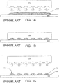
- a hard stamp 100 such as one made from glass or steel, presses down upon a droplet of replication material 110, such as an UV-curable polymer, that has been previously dispensed on a substrate wafer 120.
- Replication material 110 may also be a resin cured with a catalyst, or a heated thermoplastic.
- the hard stamp 100 squeezes down on the polymer the polymer conforms to the master, as shown in FIG. 1B , and is cured into a solid state by means such as UV light exposure, heat, or a catalyst.
- FIG. 1A a hard stamp 100, such as one made from glass or steel, presses down upon a droplet of replication material 110, such as an UV-curable polymer, that has been previously dispensed on a substrate wafer 120.
- Replication material 110 may also be a resin cured with a catalyst, or a heated thermoplastic.
- the hard stamp 100 parts from the substrate wafer 120, leaving behind a lens layer 150 comprising individual formed lenses 130. If an excess of replication material 110 is provided, a residual layer 140 may also be present beneath the formed lenses.
- the master is a soft stamp.
- FIG. 2A shows a soft stamp 200 that may be made from silicone rubbers such as polydimethylsiloxane ("PDMS").
- Replication material 210 such as UV epoxy polymer, is dispensed onto the soft stamp 210.
- FIG. 2B shows the soft stamp 210 pressing down upon the substrate wafer 120, transferring the polymer 210 onto the substrate wafer 120, and casting the polymer 210 into lens.
- the polymer 210 is cured into a solid state by means such as UV exposure. Parting of the soft stamp 200 from the substrate wafer 120 leaves behind a lens layer 230 having multiple individual lenses 220, as shown in FIG. 2C .
- a lens After a lens is molded, it may experience shape change while its polymer cures, an example of which is shrinkage or sagging. Shrinkage is related to curing properties of the lens material, such as epoxy. Shape change such as shrinkage results in a lens product that deviates from the shape of the stamp, and which may deviate from intended lens design specifications.
- shrinkage is compensated for by using a mold, such as hard stamp 100 that has a shrinkage-compensated shape to produce a pre-shrunk, oversized, lens that is slightly larger than the desired goal.
- a mold such as hard stamp 100 that has a shrinkage-compensated shape to produce a pre-shrunk, oversized, lens that is slightly larger than the desired goal.
- the hope is that as the oversized lens shrinks to a smaller size, the final form will meet the intended lens design specifications.
- This approach is a trial-and- error process that is often cumbersome because, among other reasons, shrinkage is sometimes not exactly as predicted and may vary with temperature and precise material composition.
- FIGs. 3A through 3H illustrate an example of this prior-art process.
- a first trial master 300 is made to include a cavity that matches shape of the intended lens.
- the first trial master 300 is used to cast a polymer 310 onto a substrate 120, as shown in FIGs. 3A , to form a first trial lens 320, as shown in FIG. 3B .
- the first trial lens is then discarded.
- the second trial master 305 is used to cast a larger amount of polymer 315 onto the substrate 120, as shown in FIG. 3E , thereby forming a second trial lens 325, as shown in FIG. 3F .
- the second trial lens 325 eventually shrinks from its initially molded dimensions 334 to a second smaller lens 335, as shown in FIG. 3G , during curing if it is formed from a UV cured polymer or a catalytically cured epoxy polymer, or during cooling if it is formed from a thermoplastic. Ultimately this second smaller lens 335 is sufficiently close to the intended lens specifications.
- two masters are used to cast a lens on a flat substrate.
- the first master alternatively known as the blob mold, and as illustrated in FIG. 4A
- the first lens is used to cast onto substrate 120 a first lens, which is then at least partially cured, during curing it is allowed to shrink.
- the first lens becomes a pre-final lens 410, alternatively known as a blob 410.
- the amount of lens material that is used for the blob 410 typically constitutes most, but not all, of total material that is expected to be used for the final lens. For example, in an embodiment, approximately 95% to 99% of the intended total of lens material is used to cast the blob 410. Once cast, the blob is cured sufficiently that most or all shrinkage the blob will undergo occurs. Since the blob contains most of the total material of the final lens, most of the bulk or large scale shrinkage effects of the blob have happened in the blob 410 when this curing step is complete.
- the blob 410 may closely approximate the intended design specs of the desired final lens.
- the blob 410 may have dimensional measurements that are up to 10 micrometers smaller than those of the desired final lens.
- the second master is used in a second molding operation to transfer a thin layer of additional polymer 420 onto the blob 410, as shown in FIG. 4B .
- the second master alternatively known as the lens mold, may have the exact lens shape as the desired final lens, or in an alternative embodiment may include a small modification for shrinkage compensation vis-à-vis the desired final lens.
- the amount of additional material transferred onto the blob 410 during the second molding operation may be, for example, approximately 1% to 5% of the total amount of lens material, the sum of blob material and additional material being approximately 100% of the lens material of the finished lens.
- this thin layer 420 Due to the small amount of lens material that is used to cast the thin layer 420, this thin layer 420 only experiences slight shrinkage relative to final lens shape. While the material of thin layer 420 may be the same or a similar material to that of the blob, because shrinkage in a particular dimension is proportional to the amount of material present and thin layer 420 is much thinner than the blob, shrinkage of the thin layer represents a smaller change in overall lens dimensions than would shrinkage of an entire lens. The shrinkage effects of thin layer 420 on final shape of the thin layer 420 are therefore significantly reduced from those of the blob, and the thin layer backfills and compensates for shrinkage of the blob. As a result, the final lens 430, comprising the blob 410 and the thin layer 420, should be sufficiently close to the designed shape of the desired final lens shape to meet lens design specifications.
- an interface may exist between the blob 410 and the thin layer 420.
- the blob 410 and the thin layer 420 may be made of the same lens material or a material with the same or similar optical indices including the index of refraction as the blob 410.
- thin layer material 420 has lower viscosity than blob material but the same or similar index of refraction to enable easy molding of the thin layer 420.
- thin layer material 420 is the same material as blob 410 and has the same index of refraction, in another embodiment it has a difference in index of refraction from blob 410 within 5% of that of blob 410, and in an alternative embodiment a difference in index of refraction within 10%.
- thin layer 420 adheres directly to blob 410 with no need for an interfacial layer, and has an index of refraction sufficiently close to that of the blob 410 that essentially no refraction occurs at a boundary 422 of thin layer 420 to blob 410.
- an interfacial substance such as an index matching and bonding material may be dispensed at the potential interface, at the boundary 422 between thin layer 420 and blob 410.
- additional process steps may be employed so as to mitigate any possible interface effect. For example, a reflow step may be used to diminish the interface between the blob 410 and the thin layer 420 by blending the material of blob and thin layer at the interface, such that some of thin layer 420 merges into and thickens blob 410.
- a lens cast on a flat substrate may experience shrinkage primarily in the vertical direction.
- the compressible, rubber-like, nature of PDMS may also contribute to shrinkage and deformation.
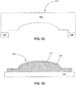
- a first master 500 as shown in FIG. 5A
- a second master 550 is constituted by adding one or several spacers 540 to the first master 500, as shown in FIG. 5C .
- the second master 550 is used to transfer a thin layer 520 onto the blob 510, as shown in FIG. 5D .
- the final lens shape 530 of blob 510 plus thin layer 520 is sufficiently close to the intended design specs of the desired final lens shape as to need no further compensation; if correction is required the magnitude of subsequent master revisions is much reduced from that required with the prior lensmaking procedures.
- a lens having a lens-in-pocket form such as where spacers 600, positioned between lenses 610, are situated on a substrate 120, and as shown in FIG. 6A may be fabricated.
- a suspended lens 620 may be fabricated, such as where lens 620 is positioned between and elevated with respect to spacers 600, as shown in FIG. 6B .
- Lens-in-pocket or suspended lenses may present additional challenges to control lens deformation because of forces like lateral stresses from the side wall of the spacers, as illustrated in FIG. 7A .
- Master 720 is used to cast a convex lens-in-pocket form 710 onto a substrate 120, where convex lens-in-pocket form 710 is bounded by spacers 700.
- Voids 730 serve as overflow space that permits the side 740 of the lens to overflow.
- Forces such as the lateral stress 750 may make it difficult to predict shrinkage compensation, and impair process repeatability when shrinkage-compensated molds, such as that of FIG. 3E , are used.
- the lateral stress 750 may induce a lateral deformity or shrinkage, which may be restrained by spacers 700 thereby causing further lens deformations.
- FIG. 7B An example that illustrates this phenomenon is shown in FIG. 7B .
- a master 725 is used to cast onto a substrate 120 a concave lens-in-pocket form 715 which is bounded by spacers 700.
- Voids 735 at periphery of master 725 serve as overflow space that permits the side 745 of the lens to overflow as well as allowing for minor misalignments of master 725 to substrate 120. Forces such as lateral stress 755 may make it difficult to control shrinkage compensation.
- a concave embodiment may have more pronounced lateral stress effects than many convex embodiments.
- the overflowed lens material at the lens side 745 may magnify the lateral stress 755, and may potentially cause significant lateral deformity or shrinkage.
- the level of difficulty of compensating for shrinkage may be increase, in part due to possible variations in vertical and/or lateral deformations or shrinkages.
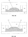
- a first master such as a soft PDMS master 820
- a second master such as a soft PDMS master 825
- a second master is used to transfer a small amount of lens material onto the pre-final lens 810, thereby forming a thin layer 815, as shown in FIG. 8B .
- the pre-final lens 810 has been casted by the master 820 as shown in FIG.
- vertical spacers or shims 805 ( FIG. 8C ) are added to spacers 800. Then the same master 820 is re-used with some additional lens material to form a thin layer 815 onto the pre-final lens 810, as shown in FIG. 8C ; the vertical spacers or shims 805 operate to control thickness of the thin upper layer 815.
- the pre-final lens 810 may constitute approximately 95% to 99% of the entire amount of lens material; since shrinkage is typically proportional to volume most of the shrinkage or deformation effect occurs prior to adding thin layer 815.
- the pre-final lens 810 may have dimensional measurements that are up to ten micrometers less than those of the desired final lens shape, thereby closely approximating the desired final lens shape.
- an interface may exist between the pre-final lens 810 and the thin layer 815, and the interface may produce surface related errors, such as light distortion, refraction and reflection at the interface.
- the pre-final lens 810 and the thin layer 815 may be made from the same lens material, or a different material with the same or similar optical refractive index, in order to reduce or eliminate reflection and refraction at the interface. Further, an interfacial substance such as an index matching material may be dispensed at the potential interface. Following the casting of the thin layer 815, an additional process step, such as a reflow step, may be employed so as to mitigate interface effects by blending the thin layer 815 into blob 810.
- a suspended lens similar to the lens-in-pocket form, is bounded by spacers.
- both the upper surface and the lower surface need molds while the lens is casted.
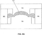
- a first upper master 922 and a first lower master 924 are used to cast a pre-final lens 910 while being bounded by spacers 900.
- a second upper master 926 FIG. 9A
- a second lower master 928 may each be used to transfer a small amount of lens material onto the upper surface and the lower surface of the pre-final lens 910, thereby forming a thin upper layer 912 and a thin lower layer 914.
- vertical spacers or shims 905 FIG. 9C
- the same upper master 922 and the same lower master 924 as used for initial molding of the pre-final form are used to form the thin upper layer 912 and the thin lower layer 914 onto the pre-final lens 910, as shown in FIG. 9C ; the vertical spacers 905 operate to control thickness of the thin upper layer 912 and the thin lower layer 914.
- the pre-final lens 910 may constitute approximately 95% to 99% of the entire amount of lens material, thereby most of the shrinkage or deformation effect is in the pre-final lens.
- the pre-final lens 910 may include dimensional measurements that are up to 10 micrometers less than those of the desired final lens shape, thereby closely approximating the desired final lens shape while allowing for additional material.
- an interface may exist between the pre-final lens 910 and the upper and low thin layers 912 and 914, and this interface may produce surface related errors, such as light distortion, as previously discussed with reference to the lens-in-pocket form. Interface effects can be reduced or eliminated by using the same lens material, or material with the same or similar optical indexes, for both the pre-final lens 910 and the thin upper and lower layers 912 and 914. Further, an interfacial substance such as an index matching material may be dispensed at the potential interface.
- a reflow or other process step may be employed so as to mitigate the possible interface effect by blending thin upper and lower layers 912, 914 with material of the pre-final lens 910 at the interface.
- the method of forming lenses herein described is adaptable to forming lenses of concave, convex, spherical, or aspherical form; the shape of the resulting lenses is determined by shape of the masters used for forming the lenses.
Landscapes
- Physics & Mathematics (AREA)
- Engineering & Computer Science (AREA)
- Manufacturing & Machinery (AREA)
- General Physics & Mathematics (AREA)
- Optics & Photonics (AREA)
- Health & Medical Sciences (AREA)
- Ophthalmology & Optometry (AREA)
- Mechanical Engineering (AREA)
- Casting Or Compression Moulding Of Plastics Or The Like (AREA)
Abstract

Description
- This disclosure relates generally to optical objects that are fabricated by molding, and in particular but not exclusively, relates to wafer level optical lenses that are molded with masters.
- Mobile phones, PDAs, laptop computers and other electronic devices often contain imaging devices such as cameras assembled as wafer level optical devices. The main components of a wafer level camera typically include a lens assembly of one or more stacked lenses, and an underlying image sensor. Wafer level cameras are manufactured by wafer level packaging technologies that include processes such as forming opto-wafers, aligning several layers of wafers, dicing, and finally packaging individual camera modules.
- An opto-wafer contains a multitude of small individual lenses that are fabricated onto a substrate wafer, and may be manufactured with techniques such as using a master wafer, mold, or stamp, to reproduce lenses onto a substrate wafer. Each opto-wafer typically has multiple lenses and/or spacers; these wafers are cut during dicing such that each camera module typically inherits only one lens and/or spacers from each opto-wafer.
- A lens, such as a lens for use in a wafer-level camera, is made by forming a polymeric material with at least one master to form a pre-final lens. The pre-final lens is at least partially cured, during which it may sag or shrink. An aliquot of polymeric material is added to the lens and formed with the same master with a spacer, or with a second master, to form a first surface layer that provides correction between the pre-final lens shape and a final desired lens shape. In an embodiment, the surface layer has similar or identical index of refraction to the pre-final lens. In an embodiment the lens is formed on a substrate. In an embodiment, a send aster, or master pair, are used to form a lens having upper and lower curvature, with a second aliquot of polymeric material forming a second surface layer on a surface of the lens opposite to the first surface layer.
- According to an aspect of the invention, there is provided a lens comprising a blob that forms a majority of a final volume of the lens, the blob being made of a moldable material that experiences shrinkage during curing, and a top layer formed atop the blob, wherein a combination of the blob and the top layer conforms to, or closely approximates, a desired final lens shape, and wherein an optical index of refraction of the top layer is similar to an index of refraction of the blob.
- Advantageously the top layer comprises a lens material having a difference in index of refraction from the blob within 10% of an index of refraction of the blob.
- Advantageously the blob and the top layer form an interface that is substantially filled with an index matching material.
- The lens may include a bottom thin layer beneath the blob, the bottom thin layer having an index of refraction substantially similar to an index of refraction of the blob, wherein especially the blob portion and the bottom thin layer form an interface that is substantially filled with an index matching and bonding material.
- Expediently the blob forms approximately 95% to 99% of a volume of the lens, and/or the blob has dimensional measurements that are up to approximately 10 micrometers less than a design specification of the lens.
- Advantageously the blob includes a deformity, wherein the top layer and/or the bottom layer corrects the deformity so that the lens meets a design specification.
- Expediently the deformity corresponds to shrinkage of the blob after molding and/or during curing.
- According to a further aspect of the invention there is provided a method of forming a lens, comprising using at least one master comprising a top master and/or a bottom master to respectively form a top surface and/or a bottom surface of a pre-final lens by molding a lens material, and inserting at least one spacer between the top master and the bottom master or inserting at least one spacer beneath the top master and/or atop the bottom master, and applying additional lens material between the pre-final lens and the top master, and/or between the pre-final lens and the bottom master, and using the set of masters to form the additional lens material into a top layer atop the pre-final lens and/or a bottom layer beneath the pre-final lens; or using a second master to form a top layer atop the pre-final lens and/or a bottom layer beneath the pre final lens; wherein the pre-final lens forms a majority of a final volume of the lens.
- Advantageously in the step of using at least one master, the pre-final lens is formed using a first one of the top master and the bottom master, in the step of using the second master, the second master is used to form the top layer atop the pre-final lens, and wherein the pre-final lens includes a deformity due to shrinkage of the pre-final lens after molding the pre-final lens, and wherein the top layer substantially corrects the deformity.
- Expediently in the step of using at least one master the pre-final lens is formed on a flat substrate.
- The method may comprise using a third master to form a bottom layer beneath the pre-final lens. Additionally or alternatively, in the step of using the second master, the second master may comprise a combination of the first master and a spacer.
- Advantageously in the step of using the second master, the top layer is formed using the second master.
- Advantageously in the step of using the second master, the top layer is formed of a material that shrinks after molding.
- Expediently in the step of inserting at least one spacer, the at least one spacer is inserted beneath the top master; and in the step of applying additional lens material, the additional lens material is applied between the pre-final lens and the top master; and the top master forms the top layer atop the pre-final lens, the spacer controlling a thickness of the top layer.
- Advantageously in the step of using at least one master, the top master is used to form the pre-final lens on a flat substrate.
- Non-limiting and non-exhaustive embodiments of the invention are described with reference to the following figures, wherein like reference numerals refer to like parts throughout the various views unless otherwise specified.
-
FIGs. 1A through 1C are cross sectional views showing the PRIOR ART process of lenses being formed on a substrate by a hard stamp. -
FIGs. 2A through 2C are cross sectional views showing the process of lenses being formed on a substrate by a soft stamp. -
FIGs. 3A through 3H are cross sectional views showing a trial and error process wherein a mold is modified in successive rounds to match the desired specs of the final lens product. -
FIGs. 4A and 4B are cross sectional views showing a process wherein a lens is cast in two molding operations, each using its own master, to produce a desired final lens product. -
FIGs. 5A through 5D are cross sectional views showing a process wherein a lens is cast in two molding operations with essentially the same master to produce a desired final lens product. -
FIGs. 6A and 6B are cross sectional views showing embodiments of a lens-in-pocket form and a suspended lens. -
FIGs. 7A and 7B are cross sectional views showing prior art embodiments of a convex lens-in-pocket and a concave lens-in-pocket, respectively. -
FIGs. 8A through 8C are cross sectional views showing a process of casting a lens-in-pocket with two masters and a process of casting a lens-in-pocket with a combination of one master and one or several vertical spacers. -
FIGs. 9A through 9C are cross sectional views showing a process of casting a suspended lens with two sets of masters and a process of casting a suspended lens with a combination of one set of masters and one or several vertical spacers. - In the following description, numerous details and alternative are set forth to provide a thorough understanding of the present invention.
- Reference throughout this specification to "one embodiment" or "an embodiment" means that a particular feature, structure, or characteristic described in connection with the embodiment is included in at least one embodiment of the present invention. Thus, the appearances of the phrases "in one embodiment" or "in an embodiment" in various places throughout this specification are not necessarily all referring to the same embodiment. Furthermore, the particular features, structures, or characteristics herein described may be combined in a suitable manner in one or more embodiments.
- Lens replication for volume production of wafer-level optical systems may be done by replication techniques such as molding. In one example, the master is a hard stamp. As shown in
FIG. 1A , ahard stamp 100, such as one made from glass or steel, presses down upon a droplet ofreplication material 110, such as an UV-curable polymer, that has been previously dispensed on asubstrate wafer 120.Replication material 110 may also be a resin cured with a catalyst, or a heated thermoplastic. As thehard stamp 100 squeezes down on the polymer, the polymer conforms to the master, as shown inFIG. 1B , and is cured into a solid state by means such as UV light exposure, heat, or a catalyst. InFIG. 1C , thehard stamp 100 parts from thesubstrate wafer 120, leaving behind alens layer 150 comprising individual formedlenses 130. If an excess ofreplication material 110 is provided, aresidual layer 140 may also be present beneath the formed lenses. In another example, the master is a soft stamp.FIG. 2A shows asoft stamp 200 that may be made from silicone rubbers such as polydimethylsiloxane ("PDMS").Replication material 210, such as UV epoxy polymer, is dispensed onto thesoft stamp 210.FIG. 2B shows thesoft stamp 210 pressing down upon thesubstrate wafer 120, transferring thepolymer 210 onto thesubstrate wafer 120, and casting thepolymer 210 into lens. Thepolymer 210 is cured into a solid state by means such as UV exposure. Parting of thesoft stamp 200 from thesubstrate wafer 120 leaves behind alens layer 230 having multipleindividual lenses 220, as shown inFIG. 2C . - After a lens is molded, it may experience shape change while its polymer cures, an example of which is shrinkage or sagging. Shrinkage is related to curing properties of the lens material, such as epoxy. Shape change such as shrinkage results in a lens product that deviates from the shape of the stamp, and which may deviate from intended lens design specifications.
- Several methods may be used to remedy the undesirable shrinkage effect. In one approach, shrinkage is compensated for by using a mold, such as
hard stamp 100 that has a shrinkage-compensated shape to produce a pre-shrunk, oversized, lens that is slightly larger than the desired goal. The hope is that as the oversized lens shrinks to a smaller size, the final form will meet the intended lens design specifications. This approach is a trial-and- error process that is often cumbersome because, among other reasons, shrinkage is sometimes not exactly as predicted and may vary with temperature and precise material composition. -
FIGs. 3A through 3H illustrate an example of this prior-art process. Afirst trial master 300 is made to include a cavity that matches shape of the intended lens. Thefirst trial master 300 is used to cast apolymer 310 onto asubstrate 120, as shown inFIGs. 3A , to form afirst trial lens 320, as shown inFIG. 3B . As thefirst trial lens 320 solidifies, cures, and stabilizes, it shrinks from its initially moldeddimensions 332 to a firstsmaller lens 330, as shown inFIG. 3C . Comparing the firstsmaller lens 330 with intended lens specifications enables an engineer to estimate the extent to which the cavity of thefirst trial master 300 needs to be enlarged in order to produce asecond trial master 305, as shown inFIG. 3D ; the first trial lens is then discarded. Then, in a separate molding operation, thesecond trial master 305 is used to cast a larger amount ofpolymer 315 onto thesubstrate 120, as shown inFIG. 3E , thereby forming asecond trial lens 325, as shown inFIG. 3F . Thesecond trial lens 325 eventually shrinks from its initially moldeddimensions 334 to a secondsmaller lens 335, as shown inFIG. 3G , during curing if it is formed from a UV cured polymer or a catalytically cured epoxy polymer, or during cooling if it is formed from a thermoplastic. Hopefully this secondsmaller lens 335 is sufficiently close to the intended lens specifications. If not, then this iterative trial-and-error process will continue, until afinal lens product 340 that sufficiently resembles the intended lens shape is produced, as shown inFIG. 3F . Two, three, or more rounds of mold machining are often required to eventually produce a final master that can be used to mold a lens that meets the lens design specifications. - We propose a process that allows avoidance of the trial-and-error, iterative, process, while producing a final lens-on-flat-substrate by using two or more successive and additive molding operations. In one embodiment, two masters are used to cast a lens on a flat substrate. In a first molding operation, the first master, alternatively known as the blob mold, and as illustrated in
FIG. 4A , is used to cast onto substrate 120 a first lens, which is then at least partially cured, during curing it is allowed to shrink. After shrinking, the first lens becomes apre-final lens 410, alternatively known as ablob 410. The amount of lens material that is used for theblob 410 typically constitutes most, but not all, of total material that is expected to be used for the final lens. For example, in an embodiment, approximately 95% to 99% of the intended total of lens material is used to cast theblob 410. Once cast, the blob is cured sufficiently that most or all shrinkage the blob will undergo occurs. Since the blob contains most of the total material of the final lens, most of the bulk or large scale shrinkage effects of the blob have happened in theblob 410 when this curing step is complete. - The
blob 410 may closely approximate the intended design specs of the desired final lens. For example, theblob 410 may have dimensional measurements that are up to 10 micrometers smaller than those of the desired final lens. - Following shrinkage of the
blob 410, the second master is used in a second molding operation to transfer a thin layer ofadditional polymer 420 onto theblob 410, as shown inFIG. 4B . The second master, alternatively known as the lens mold, may have the exact lens shape as the desired final lens, or in an alternative embodiment may include a small modification for shrinkage compensation vis-à-vis the desired final lens. The amount of additional material transferred onto theblob 410 during the second molding operation may be, for example, approximately 1% to 5% of the total amount of lens material, the sum of blob material and additional material being approximately 100% of the lens material of the finished lens. Due to the small amount of lens material that is used to cast thethin layer 420, thisthin layer 420 only experiences slight shrinkage relative to final lens shape. While the material ofthin layer 420 may be the same or a similar material to that of the blob, because shrinkage in a particular dimension is proportional to the amount of material present andthin layer 420 is much thinner than the blob, shrinkage of the thin layer represents a smaller change in overall lens dimensions than would shrinkage of an entire lens. The shrinkage effects ofthin layer 420 on final shape of thethin layer 420 are therefore significantly reduced from those of the blob, and the thin layer backfills and compensates for shrinkage of the blob. As a result, thefinal lens 430, comprising theblob 410 and thethin layer 420, should be sufficiently close to the designed shape of the desired final lens shape to meet lens design specifications. - Due to the several separate and additive molding operations, an interface may exist between the
blob 410 and thethin layer 420. To prevent distortion, reflections, or scattering from such an interface, theblob 410 and thethin layer 420 may be made of the same lens material or a material with the same or similar optical indices including the index of refraction as theblob 410. In an alternative embodimentthin layer material 420 has lower viscosity than blob material but the same or similar index of refraction to enable easy molding of thethin layer 420. In all embodiment,thin layer material 420 is the same material asblob 410 and has the same index of refraction, in another embodiment it has a difference in index of refraction fromblob 410 within 5% of that ofblob 410, and in an alternative embodiment a difference in index of refraction within 10%. In an embodiment,thin layer 420 adheres directly to blob 410 with no need for an interfacial layer, and has an index of refraction sufficiently close to that of theblob 410 that essentially no refraction occurs at aboundary 422 ofthin layer 420 to blob 410. In alternative embodiments, an interfacial substance such as an index matching and bonding material may be dispensed at the potential interface, at theboundary 422 betweenthin layer 420 andblob 410. In addition or as an alternative, following the casting of thethin layer 420, additional process steps may be employed so as to mitigate any possible interface effect. For example, a reflow step may be used to diminish the interface between theblob 410 and thethin layer 420 by blending the material of blob and thin layer at the interface, such that some ofthin layer 420 merges into and thickensblob 410. - In certain situations, such as when a PDMS soft stamp is used for casting, a lens cast on a flat substrate may experience shrinkage primarily in the vertical direction. In addition, the compressible, rubber-like, nature of PDMS may also contribute to shrinkage and deformation. In another embodiment wherein two or more successive, additive, molding operations are used to produce a lens-on-flat-substrate, a
first master 500, as shown inFIG. 5A , is used to cast a pre-final lens orblob 510 onto asubstrate 120, as shown inFIG. 5B . Asecond master 550 is constituted by adding one orseveral spacers 540 to thefirst master 500, as shown inFIG. 5C . Thesecond master 550 is used to transfer athin layer 520 onto theblob 510, as shown inFIG. 5D . In many embodiments, thefinal lens shape 530 ofblob 510 plusthin layer 520 is sufficiently close to the intended design specs of the desired final lens shape as to need no further compensation; if correction is required the magnitude of subsequent master revisions is much reduced from that required with the prior lensmaking procedures. - Alternative lens forms exist in addition to the lens-on-flat-substrate form as disclosed above. For example, in an alternative embodiment, a lens having a lens-in-pocket form, such as where
spacers 600, positioned betweenlenses 610, are situated on asubstrate 120, and as shown inFIG. 6A may be fabricated. In another example, a suspendedlens 620 may be fabricated, such as wherelens 620 is positioned between and elevated with respect tospacers 600, as shown inFIG. 6B . - Lens-in-pocket or suspended lenses may present additional challenges to control lens deformation because of forces like lateral stresses from the side wall of the spacers, as illustrated in
FIG. 7A .Master 720 is used to cast a convex lens-in-pocket form 710 onto asubstrate 120, where convex lens-in-pocket form 710 is bounded byspacers 700.Voids 730 serve as overflow space that permits theside 740 of the lens to overflow. Forces such as thelateral stress 750 may make it difficult to predict shrinkage compensation, and impair process repeatability when shrinkage-compensated molds, such as that ofFIG. 3E , are used. For example, in addition to a vertical deformity or shrinkage, thelateral stress 750 may induce a lateral deformity or shrinkage, which may be restrained byspacers 700 thereby causing further lens deformations. - In addition to the effect of lateral stress from
spacers 700, the extent to which the overflowed lens material at thelens side 740 bulges into thevoids 730 may exacerbate thelateral stress 750. An example that illustrates this phenomenon is shown inFIG. 7B . Here, amaster 725 is used to cast onto a substrate 120 a concave lens-in-pocket form 715 which is bounded byspacers 700.Voids 735 at periphery ofmaster 725 serve as overflow space that permits theside 745 of the lens to overflow as well as allowing for minor misalignments ofmaster 725 tosubstrate 120. Forces such aslateral stress 755 may make it difficult to control shrinkage compensation. A concave embodiment may have more pronounced lateral stress effects than many convex embodiments. In part due to gravity, the overflowed lens material at thelens side 745 may magnify thelateral stress 755, and may potentially cause significant lateral deformity or shrinkage. Further, if there are variations in the amount of the lens material such that there is a variation in the amount of the overflowedlens material 745, then the level of difficulty of compensating for shrinkage may be increase, in part due to possible variations in vertical and/or lateral deformations or shrinkages. - Several embodiments of our process for forming a lens-in-pocket form are disclosed herein. In one embodiment, as shown in
FIG. 8A , a first master, such as asoft PDMS master 820, is used to cast apre-final lens 810 onto asubstrate 120, with thepre-final lens 810 being bounded byspacers 800. After thepre-final lens 810 has experienced shrinkage and hardened, a second master, such as asoft PDMS master 825, is used to transfer a small amount of lens material onto thepre-final lens 810, thereby forming athin layer 815, as shown inFIG. 8B . In another embodiment, after thepre-final lens 810 has been casted by themaster 820 as shown inFIG. 8A , vertical spacers or shims 805 (FIG. 8C ) are added tospacers 800. Then thesame master 820 is re-used with some additional lens material to form athin layer 815 onto thepre-final lens 810, as shown inFIG. 8C ; the vertical spacers orshims 805 operate to control thickness of the thinupper layer 815. - Structural and operational parameters for the lens-in-pocket form are similar to those of the lens-on-flat-substrate form. For example, the
pre-final lens 810 may constitute approximately 95% to 99% of the entire amount of lens material; since shrinkage is typically proportional to volume most of the shrinkage or deformation effect occurs prior to addingthin layer 815. In another example, thepre-final lens 810 may have dimensional measurements that are up to ten micrometers less than those of the desired final lens shape, thereby closely approximating the desired final lens shape. Yet in another example, an interface may exist between thepre-final lens 810 and thethin layer 815, and the interface may produce surface related errors, such as light distortion, refraction and reflection at the interface. Accordingly, thepre-final lens 810 and thethin layer 815 may be made from the same lens material, or a different material with the same or similar optical refractive index, in order to reduce or eliminate reflection and refraction at the interface. Further, an interfacial substance such as an index matching material may be dispensed at the potential interface. Following the casting of thethin layer 815, an additional process step, such as a reflow step, may be employed so as to mitigate interface effects by blending thethin layer 815 intoblob 810. - A suspended lens, similar to the lens-in-pocket form, is bounded by spacers. On the other hand, for a suspended lens, both the upper surface and the lower surface need molds while the lens is casted. Several embodiments regarding the suspended lens are disclosed herein. In one embodiment, as shown in
FIG. 9A , a firstupper master 922 and a firstlower master 924 are used to cast apre-final lens 910 while being bounded byspacers 900. After thepre-final lens 910 has experienced shrinkage, a second upper master 926 (FIG. 9B ) and a secondlower master 928 may each be used to transfer a small amount of lens material onto the upper surface and the lower surface of thepre-final lens 910, thereby forming a thinupper layer 912 and a thinlower layer 914. In another embodiment, after thepre-final lens 910 has been casted by theupper master 922 and thelower master 924, as shown inFIG. 9A , vertical spacers or shims 905 (FIG. 9C ) are added to top and bottom of thespacers 900. Then the sameupper master 922 and the samelower master 924 as used for initial molding of the pre-final form are used to form the thinupper layer 912 and the thinlower layer 914 onto thepre-final lens 910, as shown inFIG. 9C ; thevertical spacers 905 operate to control thickness of the thinupper layer 912 and the thinlower layer 914. - Structural and operational parameters for suspended lenses are similar to those of the lens-in-pocket form. For example, the
pre-final lens 910 may constitute approximately 95% to 99% of the entire amount of lens material, thereby most of the shrinkage or deformation effect is in the pre-final lens. In another example, thepre-final lens 910 may include dimensional measurements that are up to 10 micrometers less than those of the desired final lens shape, thereby closely approximating the desired final lens shape while allowing for additional material. - Yet in another example, an interface may exist between the
pre-final lens 910 and the upper and lowthin layers pre-final lens 910 and the thin upper andlower layers lower layers lower layers pre-final lens 910 at the interface. - It should be noted that the method of forming lenses herein described is adaptable to forming lenses of concave, convex, spherical, or aspherical form; the shape of the resulting lenses is determined by shape of the masters used for forming the lenses.
- The above description of illustrated embodiments of the invention, including what is described in the Abstract, is not intended to be exhaustive or to limit the invention to the precise forms disclosed. While specific embodiments of, and examples for, the invention are described herein for illustrative purposes, various modifications are possible within the scope of the invention, as those skilled in the relevant art will recognize.
- These modifications can be made to the invention in light of the above detailed description. The terms used in the following claims should not be construed to limit the invention to the specific embodiments disclosed in the specification. Rather, the scope of the invention is to be determined entirely by the following claims, which are to be construed in accordance with established doctrines of claim interpretation.
Claims (15)
- A lens comprising:a blob that forms a majority of a final volume of the lens, the blob being made of a moldable material that experiences shrinkage during curing, anda top layer formed atop the blob,wherein a combination of the blob and the top layer conforms to, or closely approximates, a desired final lens shape, andwherein an optical index of refraction of the top layer is similar to an index of refraction of the blob.
- The lens of claim 1 wherein the top layer comprises a lens material having a difference in index of refraction from the blob within 10% of an index of refraction of the blob.
- The lens of claim 1 or claim 2, wherein the blob and the top layer form an interface that is substantially filled with an index matching material.
- The lens of any one of the preceding claims, further including a bottom thin layer beneath the blob, the bottom thin layer having an index of refraction substantially similar to an index of refraction of the blob, wherein especially the blob portion and the bottom thin layer form an interface that is substantially filled with an index matching and bonding material.
- The lens of any one of the preceding claims, wherein the blob forms approximately 95% to 99% of a volume of the lens, and/or wherein the blob has dimensional measurements that are up to approximately 10 micrometers less than a design specification of the lens.
- The lens of any one of the preceding claims, wherein the blob includes a deformity, and wherein the top layer and/or the bottom layer corrects the deformity so that the lens meets a design specification.
- The lens of claim 6 wherein the deformity corresponds to shrinkage of the blob after molding and/or during curing.
- A method of forming a lens, comprising:using at least one master comprising a top master and/or a bottom master to respectively form a top surface and/or a bottom surface of a pre-final lens by molding a lens material, and inserting at least one spacer between the top master and the bottom master or inserting at least one spacer beneath the top master and/or atop the bottom master, andapplying additional lens material between the pre-final lens and the top master, and/or between the pre-final lens and the bottom master, and using the set of masters to form the additional lens material into a top layer atop the pre-final lens and/or a bottom layer beneath the pre-final lens; orusing a second master to form a top layer atop the pre-final lens and/or a bottom layer beneath the pre final lens;wherein the pre-final lens forms a majority of a final volume of the lens.
- The method of claim 8 wherein:in the step of using at least one master, the pre-final lens is formed using a first one of the top master and the bottom master,in the step of using the second master, the second master is used to form the top layer atop the pre-final lens, andwherein the pre-final lens includes a deformity due to shrinkage of the pre-final lens after molding the pre-final lens, and wherein the top layer substantially corrects the deformity.
- The method of claim 8 or 9, wherein in the step of using at least one master the pre-final lens is formed on a flat substrate.
- The method of any one of claims 8 - 10, further comprising using a third master to form a bottom layer beneath the pre-final lens, and/or wherein in the step of using the second master, the second master comprises a combination of the first master and a spacer.
- The method of claim 8 wherein in the step of using the second master, the top layer is formed using the second master.
- The method of claim 12, wherein in the step of using the second master, the top layer is formed of a material that shrinks after molding.
- The method of claim 8 wherein in the step of inserting at least one spacer, the at least one spacer is inserted beneath the top master; and
in the step of applying additional lens material, the additional lens material is applied between the pre-final lens and the top master, and
the top master forms the top layer atop the pre-final lens, the spacer controlling a thickness of the top layer. - A method of claim 14, wherein in the step of using at least one master, the top master is used to form the pre-final lens on a flat substrate.
Applications Claiming Priority (1)
| Application Number | Priority Date | Filing Date | Title |
|---|---|---|---|
| US13/024,265 US8638500B2 (en) | 2011-02-09 | 2011-02-09 | Two-stage optical object molding using pre-final form |
Publications (2)
| Publication Number | Publication Date |
|---|---|
| EP2487513A1 true EP2487513A1 (en) | 2012-08-15 |
| EP2487513B1 EP2487513B1 (en) | 2017-08-09 |
Family
ID=45655538
Family Applications (1)
| Application Number | Title | Priority Date | Filing Date |
|---|---|---|---|
| EP12154746.7A Active EP2487513B1 (en) | 2011-02-09 | 2012-02-09 | Two-Stage optical object molding using pre-final form |
Country Status (4)
| Country | Link |
|---|---|
| US (2) | US8638500B2 (en) |
| EP (1) | EP2487513B1 (en) |
| CN (1) | CN102636823B (en) |
| TW (1) | TWI448734B (en) |
Families Citing this family (13)
| Publication number | Priority date | Publication date | Assignee | Title |
|---|---|---|---|---|
| US20120242814A1 (en) | 2011-03-25 | 2012-09-27 | Kenneth Kubala | Miniature Wafer-Level Camera Modules |
| WO2013089223A1 (en) * | 2011-12-16 | 2013-06-20 | コニカミノルタ株式会社 | Method for producing lens array, and molding mold |
| US9995921B2 (en) | 2013-06-06 | 2018-06-12 | Cell Focus, LLC | Surface adhering lens |
| US9465191B2 (en) * | 2013-06-21 | 2016-10-11 | Microsoft Technology Licensing, Llc | Lenses for curved sensor systems |
| EP3142839B1 (en) | 2014-05-16 | 2020-11-18 | Heptagon Micro Optics Pte. Ltd. | Manufacture of optical elements by replication and corresponding replication tools and optical devices |
| US9798114B2 (en) * | 2014-06-17 | 2017-10-24 | Omnivision Technologies, Inc. | Concave spacer-wafer apertures and wafer-level optical elements formed therein |
| NL2015330B1 (en) | 2015-08-21 | 2017-03-13 | Anteryon Wafer Optics B V | A method of fabricating an array of optical lens elements |
| WO2017034402A1 (en) | 2015-08-21 | 2017-03-02 | Anteryon Wafer Optics B.V. | A method of fabricating an array of optical lens elements |
| CN108319033A (en) * | 2018-01-23 | 2018-07-24 | 武汉维莱特光电技术有限公司 | A kind of arrayed optical fiber collimators |
| CN108453963A (en) * | 2018-01-23 | 2018-08-28 | 武汉维莱特光电技术有限公司 | A kind of curved reflector preparation method and product based on light-cured resin |
| CN108459375A (en) * | 2018-01-23 | 2018-08-28 | 武汉维莱特光电技术有限公司 | A kind of wavelength-selective switches |
| CN108181289A (en) * | 2018-03-05 | 2018-06-19 | 北京工业大学 | The fiber end face detected towards water pollution integrates Fluorescence and Absorption Spectroscopies test device |
| JP7749294B2 (en) * | 2020-05-14 | 2025-10-06 | マジック リープ, インコーポレイテッド | Method and system for integrating refractive optics with a diffractive eyepiece waveguide display |
Citations (4)
| Publication number | Priority date | Publication date | Assignee | Title |
|---|---|---|---|---|
| US4957663A (en) * | 1986-02-13 | 1990-09-18 | U.S. Philips Corp. | Method of manufacturing optical components |
| US20040135293A1 (en) * | 2002-09-18 | 2004-07-15 | Ricoh Optical Industries Co., Ltd. | Method and mold for fabricating article having fine surface structure |
| US20080299340A1 (en) * | 2007-06-01 | 2008-12-04 | Joseph Kamienski | Over-molded thick wall parts |
| WO2010139342A1 (en) * | 2009-06-02 | 2010-12-09 | Fraunhofer-Gesellschaft zur Förderung der angewandten Forschung e. V. | Lens and method for manufacturing same |
Family Cites Families (2)
| Publication number | Priority date | Publication date | Assignee | Title |
|---|---|---|---|---|
| US8599301B2 (en) * | 2006-04-17 | 2013-12-03 | Omnivision Technologies, Inc. | Arrayed imaging systems having improved alignment and associated methods |
| JP2008296450A (en) * | 2007-05-31 | 2008-12-11 | Olympus Corp | Molding method for composite optical element |
-
2011
- 2011-02-09 US US13/024,265 patent/US8638500B2/en active Active
-
2012
- 2012-02-03 TW TW101103624A patent/TWI448734B/en active
- 2012-02-08 CN CN201210029689.1A patent/CN102636823B/en active Active
- 2012-02-09 EP EP12154746.7A patent/EP2487513B1/en active Active
-
2014
- 2014-01-27 US US14/164,877 patent/US9013797B2/en active Active
Patent Citations (4)
| Publication number | Priority date | Publication date | Assignee | Title |
|---|---|---|---|---|
| US4957663A (en) * | 1986-02-13 | 1990-09-18 | U.S. Philips Corp. | Method of manufacturing optical components |
| US20040135293A1 (en) * | 2002-09-18 | 2004-07-15 | Ricoh Optical Industries Co., Ltd. | Method and mold for fabricating article having fine surface structure |
| US20080299340A1 (en) * | 2007-06-01 | 2008-12-04 | Joseph Kamienski | Over-molded thick wall parts |
| WO2010139342A1 (en) * | 2009-06-02 | 2010-12-09 | Fraunhofer-Gesellschaft zur Förderung der angewandten Forschung e. V. | Lens and method for manufacturing same |
Also Published As
| Publication number | Publication date |
|---|---|
| US20140139934A1 (en) | 2014-05-22 |
| CN102636823A (en) | 2012-08-15 |
| US9013797B2 (en) | 2015-04-21 |
| US8638500B2 (en) | 2014-01-28 |
| TWI448734B (en) | 2014-08-11 |
| CN102636823B (en) | 2015-03-04 |
| US20120200943A1 (en) | 2012-08-09 |
| TW201239410A (en) | 2012-10-01 |
| EP2487513B1 (en) | 2017-08-09 |
Similar Documents
| Publication | Publication Date | Title |
|---|---|---|
| US9013797B2 (en) | Two-stage optical object molding using pre-final form | |
| US20070231575A1 (en) | Apparatus and method for molding object with enhanced transferability of transfer face and object made by the same | |
| NL2013093B1 (en) | Method for manufacturing a lens structure. | |
| US7885018B2 (en) | Bonded optical element and manufacturing method thereof | |
| CN102574345A (en) | Method for making ophthalmic lenses | |
| US7746573B2 (en) | Bonded optical element and manufacturing method thereof | |
| WO2017073370A1 (en) | Film mold and imprinting method | |
| JP2012252113A (en) | Method for manufacturing wafer lens | |
| JP4781001B2 (en) | Compound lens manufacturing method | |
| US20130249034A1 (en) | Optical Device, Wafer-Scale Package for One Such Optical Device and Corresponding Method | |
| Desmet et al. | Elastomeric inverse moulding and vacuum casting process characterization for the fabrication of arrays of concave refractive microlenses | |
| CN101480822B (en) | Mold device and method of use thereof | |
| CN101450514A (en) | Cam die kernel correction method and die | |
| JP6582584B2 (en) | Method for manufacturing plastic optical element | |
| KR20120068178A (en) | Mold for forming lens and lens forming method | |
| KR102456679B1 (en) | Diffraction light guide plate and manufacturing method thereof the same | |
| JP7563265B2 (en) | Method and apparatus for manufacturing plastic elements | |
| CN110154293B (en) | Manufacturing method of gel-like parts | |
| JP2011212924A (en) | Lens mold manufacturing method | |
| JP4428791B2 (en) | Optimal molding condition setting device, optimal molding condition setting method, and storage medium | |
| US10175462B2 (en) | Wafer level lens system and method of fabricating the same | |
| JP2014162012A (en) | Microstructure molding method and microstructure molding die | |
| JP4232380B2 (en) | Method for manufacturing composite optical element | |
| US8418516B2 (en) | Manufacturing method for optical element | |
| KR20120061419A (en) | Lens array module and molding method thereof |
Legal Events
| Date | Code | Title | Description |
|---|---|---|---|
| PUAI | Public reference made under article 153(3) epc to a published international application that has entered the european phase |
Free format text: ORIGINAL CODE: 0009012 |
|
| AK | Designated contracting states |
Kind code of ref document: A1 Designated state(s): AL AT BE BG CH CY CZ DE DK EE ES FI FR GB GR HR HU IE IS IT LI LT LU LV MC MK MT NL NO PL PT RO RS SE SI SK SM TR |
|
| AX | Request for extension of the european patent |
Extension state: BA ME |
|
| RIN1 | Information on inventor provided before grant (corrected) |
Inventor name: GALLAGHER, DENNIS J. Inventor name: FAN, REGIS S. |
|
| 17P | Request for examination filed |
Effective date: 20130215 |
|
| 17Q | First examination report despatched |
Effective date: 20160506 |
|
| GRAP | Despatch of communication of intention to grant a patent |
Free format text: ORIGINAL CODE: EPIDOSNIGR1 |
|
| STAA | Information on the status of an ep patent application or granted ep patent |
Free format text: STATUS: GRANT OF PATENT IS INTENDED |
|
| INTG | Intention to grant announced |
Effective date: 20170420 |
|
| GRAS | Grant fee paid |
Free format text: ORIGINAL CODE: EPIDOSNIGR3 |
|
| GRAA | (expected) grant |
Free format text: ORIGINAL CODE: 0009210 |
|
| STAA | Information on the status of an ep patent application or granted ep patent |
Free format text: STATUS: THE PATENT HAS BEEN GRANTED |
|
| AK | Designated contracting states |
Kind code of ref document: B1 Designated state(s): AL AT BE BG CH CY CZ DE DK EE ES FI FR GB GR HR HU IE IS IT LI LT LU LV MC MK MT NL NO PL PT RO RS SE SI SK SM TR |
|
| REG | Reference to a national code |
Ref country code: GB Ref legal event code: FG4D |
|
| REG | Reference to a national code |
Ref country code: CH Ref legal event code: EP Ref country code: AT Ref legal event code: REF Ref document number: 917450 Country of ref document: AT Kind code of ref document: T Effective date: 20170815 |
|
| REG | Reference to a national code |
Ref country code: IE Ref legal event code: FG4D |
|
| REG | Reference to a national code |
Ref country code: DE Ref legal event code: R096 Ref document number: 602012035537 Country of ref document: DE |
|
| REG | Reference to a national code |
Ref country code: NL Ref legal event code: MP Effective date: 20170809 |
|
| REG | Reference to a national code |
Ref country code: LT Ref legal event code: MG4D |
|
| REG | Reference to a national code |
Ref country code: AT Ref legal event code: MK05 Ref document number: 917450 Country of ref document: AT Kind code of ref document: T Effective date: 20170809 |
|
| PG25 | Lapsed in a contracting state [announced via postgrant information from national office to epo] |
Ref country code: AT Free format text: LAPSE BECAUSE OF FAILURE TO SUBMIT A TRANSLATION OF THE DESCRIPTION OR TO PAY THE FEE WITHIN THE PRESCRIBED TIME-LIMIT Effective date: 20170809 Ref country code: NL Free format text: LAPSE BECAUSE OF FAILURE TO SUBMIT A TRANSLATION OF THE DESCRIPTION OR TO PAY THE FEE WITHIN THE PRESCRIBED TIME-LIMIT Effective date: 20170809 Ref country code: HR Free format text: LAPSE BECAUSE OF FAILURE TO SUBMIT A TRANSLATION OF THE DESCRIPTION OR TO PAY THE FEE WITHIN THE PRESCRIBED TIME-LIMIT Effective date: 20170809 Ref country code: NO Free format text: LAPSE BECAUSE OF FAILURE TO SUBMIT A TRANSLATION OF THE DESCRIPTION OR TO PAY THE FEE WITHIN THE PRESCRIBED TIME-LIMIT Effective date: 20171109 Ref country code: SE Free format text: LAPSE BECAUSE OF FAILURE TO SUBMIT A TRANSLATION OF THE DESCRIPTION OR TO PAY THE FEE WITHIN THE PRESCRIBED TIME-LIMIT Effective date: 20170809 Ref country code: LT Free format text: LAPSE BECAUSE OF FAILURE TO SUBMIT A TRANSLATION OF THE DESCRIPTION OR TO PAY THE FEE WITHIN THE PRESCRIBED TIME-LIMIT Effective date: 20170809 Ref country code: FI Free format text: LAPSE BECAUSE OF FAILURE TO SUBMIT A TRANSLATION OF THE DESCRIPTION OR TO PAY THE FEE WITHIN THE PRESCRIBED TIME-LIMIT Effective date: 20170809 |
|
| REG | Reference to a national code |
Ref country code: FR Ref legal event code: PLFP Year of fee payment: 7 |
|
| PG25 | Lapsed in a contracting state [announced via postgrant information from national office to epo] |
Ref country code: LV Free format text: LAPSE BECAUSE OF FAILURE TO SUBMIT A TRANSLATION OF THE DESCRIPTION OR TO PAY THE FEE WITHIN THE PRESCRIBED TIME-LIMIT Effective date: 20170809 Ref country code: GR Free format text: LAPSE BECAUSE OF FAILURE TO SUBMIT A TRANSLATION OF THE DESCRIPTION OR TO PAY THE FEE WITHIN THE PRESCRIBED TIME-LIMIT Effective date: 20171110 Ref country code: ES Free format text: LAPSE BECAUSE OF FAILURE TO SUBMIT A TRANSLATION OF THE DESCRIPTION OR TO PAY THE FEE WITHIN THE PRESCRIBED TIME-LIMIT Effective date: 20170809 Ref country code: PL Free format text: LAPSE BECAUSE OF FAILURE TO SUBMIT A TRANSLATION OF THE DESCRIPTION OR TO PAY THE FEE WITHIN THE PRESCRIBED TIME-LIMIT Effective date: 20170809 Ref country code: BG Free format text: LAPSE BECAUSE OF FAILURE TO SUBMIT A TRANSLATION OF THE DESCRIPTION OR TO PAY THE FEE WITHIN THE PRESCRIBED TIME-LIMIT Effective date: 20171109 Ref country code: RS Free format text: LAPSE BECAUSE OF FAILURE TO SUBMIT A TRANSLATION OF THE DESCRIPTION OR TO PAY THE FEE WITHIN THE PRESCRIBED TIME-LIMIT Effective date: 20170809 Ref country code: IS Free format text: LAPSE BECAUSE OF FAILURE TO SUBMIT A TRANSLATION OF THE DESCRIPTION OR TO PAY THE FEE WITHIN THE PRESCRIBED TIME-LIMIT Effective date: 20171209 |
|
| PG25 | Lapsed in a contracting state [announced via postgrant information from national office to epo] |
Ref country code: RO Free format text: LAPSE BECAUSE OF FAILURE TO SUBMIT A TRANSLATION OF THE DESCRIPTION OR TO PAY THE FEE WITHIN THE PRESCRIBED TIME-LIMIT Effective date: 20170809 Ref country code: DK Free format text: LAPSE BECAUSE OF FAILURE TO SUBMIT A TRANSLATION OF THE DESCRIPTION OR TO PAY THE FEE WITHIN THE PRESCRIBED TIME-LIMIT Effective date: 20170809 Ref country code: CZ Free format text: LAPSE BECAUSE OF FAILURE TO SUBMIT A TRANSLATION OF THE DESCRIPTION OR TO PAY THE FEE WITHIN THE PRESCRIBED TIME-LIMIT Effective date: 20170809 |
|
| REG | Reference to a national code |
Ref country code: DE Ref legal event code: R097 Ref document number: 602012035537 Country of ref document: DE |
|
| PG25 | Lapsed in a contracting state [announced via postgrant information from national office to epo] |
Ref country code: IT Free format text: LAPSE BECAUSE OF FAILURE TO SUBMIT A TRANSLATION OF THE DESCRIPTION OR TO PAY THE FEE WITHIN THE PRESCRIBED TIME-LIMIT Effective date: 20170809 Ref country code: SK Free format text: LAPSE BECAUSE OF FAILURE TO SUBMIT A TRANSLATION OF THE DESCRIPTION OR TO PAY THE FEE WITHIN THE PRESCRIBED TIME-LIMIT Effective date: 20170809 Ref country code: EE Free format text: LAPSE BECAUSE OF FAILURE TO SUBMIT A TRANSLATION OF THE DESCRIPTION OR TO PAY THE FEE WITHIN THE PRESCRIBED TIME-LIMIT Effective date: 20170809 Ref country code: SM Free format text: LAPSE BECAUSE OF FAILURE TO SUBMIT A TRANSLATION OF THE DESCRIPTION OR TO PAY THE FEE WITHIN THE PRESCRIBED TIME-LIMIT Effective date: 20170809 |
|
| PLBE | No opposition filed within time limit |
Free format text: ORIGINAL CODE: 0009261 |
|
| STAA | Information on the status of an ep patent application or granted ep patent |
Free format text: STATUS: NO OPPOSITION FILED WITHIN TIME LIMIT |
|
| 26N | No opposition filed |
Effective date: 20180511 |
|
| PG25 | Lapsed in a contracting state [announced via postgrant information from national office to epo] |
Ref country code: SI Free format text: LAPSE BECAUSE OF FAILURE TO SUBMIT A TRANSLATION OF THE DESCRIPTION OR TO PAY THE FEE WITHIN THE PRESCRIBED TIME-LIMIT Effective date: 20170809 |
|
| PG25 | Lapsed in a contracting state [announced via postgrant information from national office to epo] |
Ref country code: MC Free format text: LAPSE BECAUSE OF FAILURE TO SUBMIT A TRANSLATION OF THE DESCRIPTION OR TO PAY THE FEE WITHIN THE PRESCRIBED TIME-LIMIT Effective date: 20170809 |
|
| REG | Reference to a national code |
Ref country code: IE Ref legal event code: MM4A |
|
| REG | Reference to a national code |
Ref country code: BE Ref legal event code: MM Effective date: 20180228 |
|
| PG25 | Lapsed in a contracting state [announced via postgrant information from national office to epo] |
Ref country code: LU Free format text: LAPSE BECAUSE OF NON-PAYMENT OF DUE FEES Effective date: 20180209 |
|
| PG25 | Lapsed in a contracting state [announced via postgrant information from national office to epo] |
Ref country code: IE Free format text: LAPSE BECAUSE OF NON-PAYMENT OF DUE FEES Effective date: 20180209 |
|
| PG25 | Lapsed in a contracting state [announced via postgrant information from national office to epo] |
Ref country code: BE Free format text: LAPSE BECAUSE OF NON-PAYMENT OF DUE FEES Effective date: 20180228 |
|
| PG25 | Lapsed in a contracting state [announced via postgrant information from national office to epo] |
Ref country code: MT Free format text: LAPSE BECAUSE OF NON-PAYMENT OF DUE FEES Effective date: 20180209 |
|
| PG25 | Lapsed in a contracting state [announced via postgrant information from national office to epo] |
Ref country code: TR Free format text: LAPSE BECAUSE OF FAILURE TO SUBMIT A TRANSLATION OF THE DESCRIPTION OR TO PAY THE FEE WITHIN THE PRESCRIBED TIME-LIMIT Effective date: 20170809 |
|
| PG25 | Lapsed in a contracting state [announced via postgrant information from national office to epo] |
Ref country code: PT Free format text: LAPSE BECAUSE OF FAILURE TO SUBMIT A TRANSLATION OF THE DESCRIPTION OR TO PAY THE FEE WITHIN THE PRESCRIBED TIME-LIMIT Effective date: 20170809 Ref country code: HU Free format text: LAPSE BECAUSE OF FAILURE TO SUBMIT A TRANSLATION OF THE DESCRIPTION OR TO PAY THE FEE WITHIN THE PRESCRIBED TIME-LIMIT; INVALID AB INITIO Effective date: 20120209 |
|
| PG25 | Lapsed in a contracting state [announced via postgrant information from national office to epo] |
Ref country code: CY Free format text: LAPSE BECAUSE OF FAILURE TO SUBMIT A TRANSLATION OF THE DESCRIPTION OR TO PAY THE FEE WITHIN THE PRESCRIBED TIME-LIMIT Effective date: 20170809 Ref country code: MK Free format text: LAPSE BECAUSE OF NON-PAYMENT OF DUE FEES Effective date: 20170809 |
|
| PG25 | Lapsed in a contracting state [announced via postgrant information from national office to epo] |
Ref country code: AL Free format text: LAPSE BECAUSE OF FAILURE TO SUBMIT A TRANSLATION OF THE DESCRIPTION OR TO PAY THE FEE WITHIN THE PRESCRIBED TIME-LIMIT Effective date: 20170809 |
|
| REG | Reference to a national code |
Ref country code: DE Ref legal event code: R082 Ref document number: 602012035537 Country of ref document: DE Representative=s name: DEHNS GERMANY PARTNERSCHAFT MBB, DE Ref country code: DE Ref legal event code: R082 Ref document number: 602012035537 Country of ref document: DE Representative=s name: DEHNSGERMANY PARTNERSCHAFT VON PATENTANWAELTEN, DE |
|
| P01 | Opt-out of the competence of the unified patent court (upc) registered |
Effective date: 20230418 |
|
| REG | Reference to a national code |
Ref country code: CH Ref legal event code: U11 Free format text: ST27 STATUS EVENT CODE: U-0-0-U10-U11 (AS PROVIDED BY THE NATIONAL OFFICE) Effective date: 20260301 |
|
| PGFP | Annual fee paid to national office [announced via postgrant information from national office to epo] |
Ref country code: GB Payment date: 20260113 Year of fee payment: 15 |
|
| PGFP | Annual fee paid to national office [announced via postgrant information from national office to epo] |
Ref country code: DE Payment date: 20260115 Year of fee payment: 15 |
|
| PGFP | Annual fee paid to national office [announced via postgrant information from national office to epo] |
Ref country code: FR Payment date: 20260109 Year of fee payment: 15 |
|
| PGFP | Annual fee paid to national office [announced via postgrant information from national office to epo] |
Ref country code: CH Payment date: 20260301 Year of fee payment: 15 |