EP2487379A1 - Fixed type constant velocity universal joint - Google Patents
Fixed type constant velocity universal joint Download PDFInfo
- Publication number
- EP2487379A1 EP2487379A1 EP10821939A EP10821939A EP2487379A1 EP 2487379 A1 EP2487379 A1 EP 2487379A1 EP 10821939 A EP10821939 A EP 10821939A EP 10821939 A EP10821939 A EP 10821939A EP 2487379 A1 EP2487379 A1 EP 2487379A1
- Authority
- EP
- European Patent Office
- Prior art keywords
- joint member
- track groove
- constant velocity
- cage
- velocity universal
- Prior art date
- Legal status (The legal status is an assumption and is not a legal conclusion. Google has not performed a legal analysis and makes no representation as to the accuracy of the status listed.)
- Granted
Links
- 238000005242 forging Methods 0.000 claims description 6
- 230000020169 heat generation Effects 0.000 abstract description 14
- 239000000314 lubricant Substances 0.000 description 9
- 229910000760 Hardened steel Inorganic materials 0.000 description 6
- 238000005520 cutting process Methods 0.000 description 6
- 230000000694 effects Effects 0.000 description 4
- 238000003780 insertion Methods 0.000 description 4
- 230000037431 insertion Effects 0.000 description 4
- 238000005461 lubrication Methods 0.000 description 4
- 230000005540 biological transmission Effects 0.000 description 2
- 238000007796 conventional method Methods 0.000 description 2
- 238000010438 heat treatment Methods 0.000 description 2
- 238000004519 manufacturing process Methods 0.000 description 2
- 239000000463 material Substances 0.000 description 2
- 238000000034 method Methods 0.000 description 2
- 239000011295 pitch Substances 0.000 description 2
- 230000002708 enhancing effect Effects 0.000 description 1
- 239000002184 metal Substances 0.000 description 1
- 238000012986 modification Methods 0.000 description 1
- 230000004048 modification Effects 0.000 description 1
- 239000011347 resin Substances 0.000 description 1
- 229920005989 resin Polymers 0.000 description 1
Images










Classifications
-
- F—MECHANICAL ENGINEERING; LIGHTING; HEATING; WEAPONS; BLASTING
- F16—ENGINEERING ELEMENTS AND UNITS; GENERAL MEASURES FOR PRODUCING AND MAINTAINING EFFECTIVE FUNCTIONING OF MACHINES OR INSTALLATIONS; THERMAL INSULATION IN GENERAL
- F16D—COUPLINGS FOR TRANSMITTING ROTATION; CLUTCHES; BRAKES
- F16D3/00—Yielding couplings, i.e. with means permitting movement between the connected parts during the drive
- F16D3/16—Universal joints in which flexibility is produced by means of pivots or sliding or rolling connecting parts
- F16D3/20—Universal joints in which flexibility is produced by means of pivots or sliding or rolling connecting parts one coupling part entering a sleeve of the other coupling part and connected thereto by sliding or rolling members
- F16D3/22—Universal joints in which flexibility is produced by means of pivots or sliding or rolling connecting parts one coupling part entering a sleeve of the other coupling part and connected thereto by sliding or rolling members the rolling members being balls, rollers, or the like, guided in grooves or sockets in both coupling parts
- F16D3/223—Universal joints in which flexibility is produced by means of pivots or sliding or rolling connecting parts one coupling part entering a sleeve of the other coupling part and connected thereto by sliding or rolling members the rolling members being balls, rollers, or the like, guided in grooves or sockets in both coupling parts the rolling members being guided in grooves in both coupling parts
-
- F—MECHANICAL ENGINEERING; LIGHTING; HEATING; WEAPONS; BLASTING
- F16—ENGINEERING ELEMENTS AND UNITS; GENERAL MEASURES FOR PRODUCING AND MAINTAINING EFFECTIVE FUNCTIONING OF MACHINES OR INSTALLATIONS; THERMAL INSULATION IN GENERAL
- F16D—COUPLINGS FOR TRANSMITTING ROTATION; CLUTCHES; BRAKES
- F16D3/00—Yielding couplings, i.e. with means permitting movement between the connected parts during the drive
- F16D3/16—Universal joints in which flexibility is produced by means of pivots or sliding or rolling connecting parts
- F16D3/20—Universal joints in which flexibility is produced by means of pivots or sliding or rolling connecting parts one coupling part entering a sleeve of the other coupling part and connected thereto by sliding or rolling members
- F16D3/22—Universal joints in which flexibility is produced by means of pivots or sliding or rolling connecting parts one coupling part entering a sleeve of the other coupling part and connected thereto by sliding or rolling members the rolling members being balls, rollers, or the like, guided in grooves or sockets in both coupling parts
- F16D3/223—Universal joints in which flexibility is produced by means of pivots or sliding or rolling connecting parts one coupling part entering a sleeve of the other coupling part and connected thereto by sliding or rolling members the rolling members being balls, rollers, or the like, guided in grooves or sockets in both coupling parts the rolling members being guided in grooves in both coupling parts
- F16D3/224—Universal joints in which flexibility is produced by means of pivots or sliding or rolling connecting parts one coupling part entering a sleeve of the other coupling part and connected thereto by sliding or rolling members the rolling members being balls, rollers, or the like, guided in grooves or sockets in both coupling parts the rolling members being guided in grooves in both coupling parts the groove centre-lines in each coupling part lying on a sphere
-
- F—MECHANICAL ENGINEERING; LIGHTING; HEATING; WEAPONS; BLASTING
- F16—ENGINEERING ELEMENTS AND UNITS; GENERAL MEASURES FOR PRODUCING AND MAINTAINING EFFECTIVE FUNCTIONING OF MACHINES OR INSTALLATIONS; THERMAL INSULATION IN GENERAL
- F16D—COUPLINGS FOR TRANSMITTING ROTATION; CLUTCHES; BRAKES
- F16D3/00—Yielding couplings, i.e. with means permitting movement between the connected parts during the drive
- F16D3/16—Universal joints in which flexibility is produced by means of pivots or sliding or rolling connecting parts
- F16D3/20—Universal joints in which flexibility is produced by means of pivots or sliding or rolling connecting parts one coupling part entering a sleeve of the other coupling part and connected thereto by sliding or rolling members
- F16D3/22—Universal joints in which flexibility is produced by means of pivots or sliding or rolling connecting parts one coupling part entering a sleeve of the other coupling part and connected thereto by sliding or rolling members the rolling members being balls, rollers, or the like, guided in grooves or sockets in both coupling parts
- F16D3/223—Universal joints in which flexibility is produced by means of pivots or sliding or rolling connecting parts one coupling part entering a sleeve of the other coupling part and connected thereto by sliding or rolling members the rolling members being balls, rollers, or the like, guided in grooves or sockets in both coupling parts the rolling members being guided in grooves in both coupling parts
- F16D3/224—Universal joints in which flexibility is produced by means of pivots or sliding or rolling connecting parts one coupling part entering a sleeve of the other coupling part and connected thereto by sliding or rolling members the rolling members being balls, rollers, or the like, guided in grooves or sockets in both coupling parts the rolling members being guided in grooves in both coupling parts the groove centre-lines in each coupling part lying on a sphere
- F16D3/2245—Universal joints in which flexibility is produced by means of pivots or sliding or rolling connecting parts one coupling part entering a sleeve of the other coupling part and connected thereto by sliding or rolling members the rolling members being balls, rollers, or the like, guided in grooves or sockets in both coupling parts the rolling members being guided in grooves in both coupling parts the groove centre-lines in each coupling part lying on a sphere where the groove centres are offset from the joint centre
-
- F—MECHANICAL ENGINEERING; LIGHTING; HEATING; WEAPONS; BLASTING
- F16—ENGINEERING ELEMENTS AND UNITS; GENERAL MEASURES FOR PRODUCING AND MAINTAINING EFFECTIVE FUNCTIONING OF MACHINES OR INSTALLATIONS; THERMAL INSULATION IN GENERAL
- F16D—COUPLINGS FOR TRANSMITTING ROTATION; CLUTCHES; BRAKES
- F16D3/00—Yielding couplings, i.e. with means permitting movement between the connected parts during the drive
- F16D3/16—Universal joints in which flexibility is produced by means of pivots or sliding or rolling connecting parts
- F16D3/20—Universal joints in which flexibility is produced by means of pivots or sliding or rolling connecting parts one coupling part entering a sleeve of the other coupling part and connected thereto by sliding or rolling members
- F16D3/22—Universal joints in which flexibility is produced by means of pivots or sliding or rolling connecting parts one coupling part entering a sleeve of the other coupling part and connected thereto by sliding or rolling members the rolling members being balls, rollers, or the like, guided in grooves or sockets in both coupling parts
- F16D3/223—Universal joints in which flexibility is produced by means of pivots or sliding or rolling connecting parts one coupling part entering a sleeve of the other coupling part and connected thereto by sliding or rolling members the rolling members being balls, rollers, or the like, guided in grooves or sockets in both coupling parts the rolling members being guided in grooves in both coupling parts
- F16D2003/22303—Details of ball cages
-
- F—MECHANICAL ENGINEERING; LIGHTING; HEATING; WEAPONS; BLASTING
- F16—ENGINEERING ELEMENTS AND UNITS; GENERAL MEASURES FOR PRODUCING AND MAINTAINING EFFECTIVE FUNCTIONING OF MACHINES OR INSTALLATIONS; THERMAL INSULATION IN GENERAL
- F16D—COUPLINGS FOR TRANSMITTING ROTATION; CLUTCHES; BRAKES
- F16D3/00—Yielding couplings, i.e. with means permitting movement between the connected parts during the drive
- F16D3/16—Universal joints in which flexibility is produced by means of pivots or sliding or rolling connecting parts
- F16D3/20—Universal joints in which flexibility is produced by means of pivots or sliding or rolling connecting parts one coupling part entering a sleeve of the other coupling part and connected thereto by sliding or rolling members
- F16D3/22—Universal joints in which flexibility is produced by means of pivots or sliding or rolling connecting parts one coupling part entering a sleeve of the other coupling part and connected thereto by sliding or rolling members the rolling members being balls, rollers, or the like, guided in grooves or sockets in both coupling parts
- F16D3/223—Universal joints in which flexibility is produced by means of pivots or sliding or rolling connecting parts one coupling part entering a sleeve of the other coupling part and connected thereto by sliding or rolling members the rolling members being balls, rollers, or the like, guided in grooves or sockets in both coupling parts the rolling members being guided in grooves in both coupling parts
- F16D2003/22309—Details of grooves
-
- Y—GENERAL TAGGING OF NEW TECHNOLOGICAL DEVELOPMENTS; GENERAL TAGGING OF CROSS-SECTIONAL TECHNOLOGIES SPANNING OVER SEVERAL SECTIONS OF THE IPC; TECHNICAL SUBJECTS COVERED BY FORMER USPC CROSS-REFERENCE ART COLLECTIONS [XRACs] AND DIGESTS
- Y10—TECHNICAL SUBJECTS COVERED BY FORMER USPC
- Y10S—TECHNICAL SUBJECTS COVERED BY FORMER USPC CROSS-REFERENCE ART COLLECTIONS [XRACs] AND DIGESTS
- Y10S464/00—Rotary shafts, gudgeons, housings, and flexible couplings for rotary shafts
- Y10S464/904—Homokinetic coupling
- Y10S464/906—Torque transmitted via radially spaced balls
Definitions
- the present invention relates to a constant velocity universal joint which is used in, for example, a power transmission system for automobiles and various industrial machines.
- a fixed type constant velocity universal joint can be taken as an example of a constant velocity universal joint used as means for transmitting a rotational force from an engine to wheels of an automobile at a constant velocity.
- the fixed type constant velocity universal joint has a structure in which two shafts, a driving shaft and a driven shaft, are coupled to each other and which is capable of transmitting rotational torque at a constant velocity even when the two shafts form an operating angle.
- a Birfield type (BJ) constant velocity universal joint and an undercut-free type (UJ) constant velocity universal joint have been widely known as the above-mentioned constant velocity universal joint.
- the fixed type constant velocity universal joint of the BJ type includes: an outer race 3 having an inner spherical surface 1 in which a plurality of track grooves 2 are equiangularly formed along an axial direction, the outer race 3 serving as an outer joint member; an inner race 6 having an outer spherical surface 4 in which a plurality of track grooves 5 are equiangularly formed in pairs with the track grooves 2 of the outer race 3 along the axial direction, the inner race 6 serving as an inner joint member; a plurality of balls 7 interposed between the track grooves 2 of the outer race 3 and the track grooves 5 of the inner race 6, for transmitting torque; and a cage 8 interposed between the inner spherical surface 1 of the outer race 3 and the outer spherical surface 4 of the inner race 6, for retaining the balls 7.
- a plurality of pockets 9 for housing the balls 7 are arranged along a circumferential direction.
- a female spline 10 is formed at an inner surface of a hole portion of the inner race 6, at an inner surface of a hole portion of the inner race 6, a female spline 10 is formed.
- a male spline 12 of a shaft 11 is fitted into the hole portion of the inner race 6, to thereby fit the male spline 12 to the female spline 10 of the inner race 6.
- a stop ring 13 for preventing dropping is fitted to an end portion of the male spline 12.
- the flexible boot 16 is formed of a bellow 18 made of a rubber material or a resin material, and a cylindrical adapter 19 made of a metal.
- the bellow 18 includes a small diameter end portion 18a fitted onto the shaft 11, a large diameter end portion 18b connected to the adapter 19, and a bent portion 18c provided between the small diameter end portion 18a and the large diameter end portion 18b.
- the small diameter end portion 18a of the bellow 18 is fixed to the shaft 11 by being fastened by a band 20.
- the adapter 19 includes a swage portion 19a swaged and fixed to the large diameter end portion 18b of the bellow 18, and an annular flange portion 19b fitted to the outer race 3.
- the end cap 15 includes a main body portion 15a as a bottomed short cylindrical member, and an annular flange portion 15b fitted to the outer race 3.
- a curvature center 02 of each of the track grooves 5 of the inner race 6 is shifted from a joint center O on the end cap side in the axial direction.
- a curvature center 01 of each of the track grooves 2 of the outer race 3 is shifted from the joint center O on the flexible boot side in the axial direction. That is, the curvature center 02 of the track groove 5 of the inner race 6 and the curvature center 01 of the track groove 2 of the outer race 3 are offset to opposite sides in the axial direction by equal distances F and F with respect to the joint center O.
- Patent Literature 1 8-ball constant velocity universal joint
- Patent Literature 2 8-ball constant velocity universal joint
- the curvature center 02 of the track groove 5 of the inner race 6 and the curvature center O1 of the track groove 2 of the outer race 3 are offset to opposite sides in the axial direction by equal distances F and F with respect to the joint center O. Therefore, as illustrated in FIG. 49 , the ball 7 forms a wedge angle ⁇ under a state in which the ball 7 is sandwiched between the tracks of the inner and outer races (ball track which is formed of the track groove 5 of the inner race 6 and the track groove 2 of the outer race 3 and in which the ball is interposed).
- the wedge angle ⁇ enables the ball 7 to push the pocket 9, and thus the cage 8 is operated smoothly.
- P1 represents a contact point of the ball 7 with respect to the track groove 2 of the outer race 3
- P2 represents a contact point of the ball 7 with respect to the track groove 5 of the inner race 6.
- the offset (track offset) is important in order to operate the cage 8, but as illustrated in FIG. 49 , a force W is applied only in a direction of an opening portion of the joint, and hence inner and outer spherical surfaces 8a and 8b of the cage are in a state of being brought into contact with the inner spherical surface 1 of the outer race 3 and the outer spherical surface 4 of the inner race 6. Therefore, when the joint is subjected to high load or rotated at high speed, this contact causes heat generation in the joint, and the durability may reduce.
- the tracks of the inner and outer races are formed into a spiral form or tilted in the axial direction, to thereby reduce the ball contact force to the tracks of the inner and outer races and further reduce the force to be applied to the cage.
- heat may be generated due to the contact between the inner spherical surfaces of the cage and the outer spherical surface of the inner race or the outer spherical surfaces of the cage and the inner spherical surface of the outer race, which may decrease the durability.
- the present invention provides a fixed type constant velocity universal joint, which is capable of preventing heat generation when high load is applied or during high-speed rotation to improve the durability, and further, suppressing a contact resistance between the cage and the inner and outer races to improve the constant velocity performance.
- a first fixed type constant velocity universal joint includes: an outer joint member including an inner surface provided with a track groove having a bottom surface being a circular arc surface; an inner joint member including an outer surface provided with a track groove having a bottom surface being a circular arc surface; a plurality of torque transmitting balls each arranged in a ball track formed of a pair of the track groove of the outer joint member and the track groove of the inner joint member; and a cage interposed between the inner surface of the outer joint member and the outer surface of the inner joint member, for retaining the plurality of torque transmitting balls.
- a curvature center of the track groove of the outer joint member and a curvature center of the track groove of the inner joint member have an offset of 0 in an axial direction.
- the track groove of the outer joint member and the track groove of the inner joint member which are tilted in opposite directions from each other with respect to an axis line, are alternately formed in a circumferential direction.
- the outer surface of the inner joint member is a spherical surface which is to be brought into sliding contact with an inner spherical surface of the cage, and the inner surface of the outer joint member is a cylindrical surface.
- the inner surface of the outer joint member may include an opening portion having a tapered portion toward an opening side.
- a second fixed type constant velocity universal joint includes: an outer joint member including an inner surface provided with a track groove having a bottom surface being a circular arc surface; an inner joint member including an outer surface provided with a track groove having a bottom surface being a circular arc surface; a plurality of torque transmitting balls each arranged in a ball track formed of a pair of the track groove of the outer joint member and the track groove of the inner joint member; and a cage interposed between the inner surface of the outer joint member and the outer surface of the inner joint member, for retaining the plurality of torque transmitting balls.
- a curvature center of the track groove of the outer joint member and a curvature center of the track groove of the inner joint member have an offset of 0 in an axial direction.
- the track groove of the outer joint member and the track groove of the inner joint member which are tilted in opposite directions from each other with respect to an axis line, are alternately formed in a circumferential direction.
- the outer surface of the inner joint member is a spherical surface which is to be brought into sliding contact with an inner spherical surface of the cage, and the inner surface of the outer joint member is a spherical surface which forms a gap together with an outer spherical surface of the cage.
- a third fixed type constant velocity universal joint includes: an outer joint member including an inner surface provided with a track groove having a bottom surface being a circular arc surface; an inner joint member including an outer surface provided with a track groove having a bottom surface being a circular arc surface; a plurality of torque transmitting balls each arranged in a ball track formed of a pair of the track groove of the outer joint member and the track groove of the inner joint member; and a cage interposed between the inner surface of the outer joint member and the outer surface of the inner joint member, for retaining the plurality of torque transmitting balls.
- a curvature center of the track groove of the outer joint member and a curvature center of the track groove of the inner joint member have an offset of 0 in an axial direction.
- the track groove of the outer joint member and the track groove of the inner joint member which are tilted in opposite directions from each other with respect to an axis line, are alternately formed in a circumferential direction.
- the outer surface of the inner joint member is a spherical surface which is to be brought into sliding contact with an inner spherical surface of the cage, and the inner surface of the outer joint member is an elliptical surface which forms a gap together with an outer spherical surface of the cage.
- a fourth fixed type constant velocity universal joint includes: an outer joint member including an inner surface provided with a track groove having a bottom surface being a circular arc surface; an inner joint member including an outer surface provided with a track groove having a bottom surface being a circular arc surface; a plurality of torque transmitting balls each arranged in a ball track formed of a pair of the track groove of the outer joint member and the track groove of the inner joint member; and a cage interposed between the inner surface of the outer joint member and the outer surface of the inner joint member, for retaining the plurality of torque transmitting balls.
- a curvature center of the track groove of the outer joint member and a curvature center of the track groove of the inner joint member have an offset of 0 in an axial direction.
- the track groove of the outer joint member and the track groove of the inner joint member which are tilted in opposite directions from each other with respect to an axis line, are alternately formed in a circumferential direction.
- the inner surface of the outer joint member is a spherical surface which is to be brought into sliding contact with an outer spherical surface of the cage, and the outer surface of the inner joint member is a cylindrical surface.
- a fifth fixed type constant velocity universal joint includes: an outer joint member including an inner surface provided with a track groove having a bottom surface being a circular arc surface; an inner joint member including an outer surface provided with a track groove having a bottom surface being a circular arc surface; a plurality of torque transmitting balls each arranged in a ball track formed of a pair of the track groove of the outer joint member and the track groove of the inner joint member; and a cage interposed between the inner surface of the outer joint member and the outer surface of the inner joint member, for retaining the plurality of torque transmitting balls.
- a curvature center of the track groove of the outer joint member and a curvature center of the track groove of the inner joint member have an offset of 0 in an axial direction.
- the track groove of the outer joint member and the track groove of the inner joint member which are tilted in opposite directions from each other with respect to an axis line, are alternately formed in a circumferential direction.
- the inner surface of the outer joint member is a spherical surface which is to be brought into sliding contact with an outer spherical surface of the cage, and the outer surface of the inner joint member is a spherical surface which forms a gap together with an inner spherical surface of the cage.
- a sixth fixed type constant velocity universal joint includes: an outer joint member including an inner surface provided with a track groove having a bottom surface being a circular arc surface; an inner joint member including an outer surface provided with a track groove having a bottom surface being a circular arc surface; a plurality of torque transmitting balls each arranged in a ball track formed of a pair of the track groove of the outer joint member and the track groove of the inner joint member; and a cage interposed between the inner surface of the outer joint member and the outer surface of the inner joint member, for retaining the plurality of torque transmitting balls.
- a curvature center of the track groove of the outer joint member and a curvature center of the track groove of the inner joint member have an offset of 0 in an axial direction.
- the track groove of the outer joint member and the track groove of the inner joint member which are tilted in opposite directions from each other with respect to an axis line, are alternately formed in a circumferential direction.
- the inner surface of the outer joint member is a spherical surface which is to be brought into sliding contact with an outer spherical surface of the cage, and the outer surface of the inner joint member is an elliptical surface which forms a gap together with an inner spherical surface of the cage.
- the track offset is set to 0, and the adjacent track grooves are alternately intersected.
- forces alternately act on adjacent pocket portions, and hence wedge angles in opposite directions are alternately generated. Therefore, a cage position is stabilized at a median position of the inner and outer races.
- the inner surface of the outer joint member is a cylindrical surface as in the first fixed type constant velocity universal joint, setting property of the cage into the outer joint member and workability of the outer joint member can be improved.
- the outer spherical surface of the cage is a convex spherical surface, and hence the inner surface of the outer joint member and the outer spherical surface of the cage have little contact with each other.
- the cage position is determined.
- the outer surface of the inner joint member is a cylindrical surface as in the fourth fixed type constant velocity universal joint, setting property of the inner joint member into the cage and workability of the inner joint member can be improved.
- the inner spherical surface of the cage is a concave spherical surface, and hence the outer surface of the inner joint member and the inner spherical surface of the cage have little contact with each other.
- the cage position is determined.
- finish working of the inner surface of the outer joint member may be omitted.
- the inner surface of the outer joint member may be formed by forging, and further, finish working of an outer surface of the cage may be omitted.
- finish working of the outer surface of the inner joint member may be omitted.
- the outer surface of the inner joint member may be formed by forging, and further, finish working of an inner surface of the cage may be omitted.
- the track groove may be formed by forging, or may be formed by mechanical working.
- a number of the plurality of torque transmitting balls may be selected among six, eight, and ten.
- the curvature center of the track groove of the outer joint member and the curvature center of the track groove of the inner joint member may be shifted from a joint center in a radial direction.
- the curvature center of the track groove of the outer joint member can be displaced in a direction more widely spaced apart from the track groove than the joint center, and the curvature center of the track groove of the outer joint member can be displaced in a direction more approaching the track groove than the joint center.
- the above-mentioned fixed type constant velocity universal joints may be used in a propeller shaft for an automobile.
- the inner surface of the outer joint member is a cylindrical surface as in the first fixed type constant velocity universal joint
- setting property of the cage into the outer joint member and workability can be improved.
- the production cost can be reduced and the productivity can be improved.
- the cage position is determined. Even in a case where there is no restriction of the cage by the outer joint member, the function as the fixed type constant velocity universal joint can be stably exerted.
- the inner surface of the outer joint member does not contact to the outer spherical surface of the cage, and in the first fixed type constant velocity universal joint, a contact area is small even when the inner surface of the outer joint member is brought into contact with the outer spherical surface of the cage. Therefore, in those fixed type constant velocity universal joints, the inner surface of the outer joint member and the outer spherical surface of the cage do not need to be subjected to high accuracy working such as grinding after heat treatment or hardened steel cutting. Thus, the cost can be reduced.
- the outer surface of the inner joint member is a cylindrical surface as in the fourth fixed type constant velocity universal joint, setting property of the inner joint member into the cage and workability of the inner joint member can be improved.
- the production cost can be reduced and the productivity can be improved,
- the cage position is determined. Even in a case where there is no restriction of the cage by the inner joint member, the function as the fixed type constant velocity universal joint can be stably exerted.
- the outer surface of the inner joint member does not contact to the inner spherical surface of the cage, and in the fourth fixed type constant velocity universal joint, a contact area is small even when the outer surface of the inner joint member is brought into contact with the inner spherical surface of the cage. Therefore, in those fixed type constant velocity universal joints, the outer surface of the inner joint member and the inner spherical surface of the cage do not need to be subjected to high accuracy working such as grinding after heat treatment or hardened steel cutting. Thus, the cost can be reduced and the productivity can be improved.
- the number of balls to be used is generally six, but the present invention is also applicable to a fixed type constant velocity universal joint using eight or ten balls. When the number of balls is increased as described above, the joint can be reduced in size and weight while securing the load capacity.
- the track groove of the outer joint member can be taken large (deep). Therefore, the load capacity can be increased, and a thickness of an axial end opening portion of the track groove of the inner joint member can be increased, to thereby enable stable connection of the shaft to be fitted into a hole portion of the inner joint member. Further, when the curvature centers of the track grooves of the outer joint member and the inner joint member are displaced in a direction more approaching the track groove than the joint center O, a load capacity of the track groove of the inner joint member can be increased, and the thickness of the outer joint member can be increased. Thus, the strength is stabilized.
- the present invention is suitable for a fixed type constant velocity universal joint used in a propeller shaft for automobiles.
- FIGS. 1 to 47 embodiments of the present invention are described with reference to FIGS. 1 to 47 .
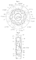
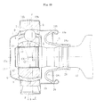
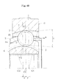
- a fixed type constant velocity universal joint includes, as illustrated in FIGS. 1 and 2 : an outer race 23 having an inner surface 21 in which a plurality of (eight) track grooves 22 are formed along an axial direction, the outer race 23 serving as an outer joint member; an inner race 26 having an outer surface 24 in which a plurality of (eight) track grooves 25 are formed along the axial direction, the inner race 26 serving as an inner joint member; a plurality of (eight) torque transmitting balls 27 arranged in ball tracks formed of pairs of the track grooves 22 of the outer race 23 and the track grooves 25 of the inner race 26; and a cage 28 interposed between the inner surface of the outer race 23 and the outer surface of the inner race, for retaining the torque transmitting balls.
- Each of the track grooves 22 of the outer race 23 has a track groove bottom which is only formed of a circular arc portion, and a curvature center 01 thereof coincides with a joint center O.
- each of the track grooves 25 of the inner race 26 has a track groove bottom which is only formed of a circular arc portion, and a curvature center 02 thereof coincides with the joint center O. That is, unlike a conventional fixed type constant velocity universal joint illustrated in FIG. 48 , the track groove 22 of the outer race 23 and the track groove 25 of the inner race 26 are not offset in the axial direction.
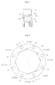
- the inner surface 21 of the outer race 23 is formed of a cylindrical surface
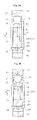
- the track grooves 22 thereof include, as illustrated in FIGS. 4 to 6 , track grooves 22a and 22b tilted in opposite directions from each other with respect to an axis line. That is, as illustrated in FIG. 5 , an axis line La of the first track groove 22a is tilted by a predetermined angle ⁇ with respect to a straight line L1 parallel to the joint axis line in a counterclockwise direction in FIG. 5 .
- An axis line Lb of the second track groove 22b is tilted by the predetermined angle ⁇ with respect to a straight line L2 parallel to the joint axis line in a clockwise direction in FIG. 5 .
- the outer race 23 is provided with through holes 30 arranged at predetermined pitches along a circumferential direction. The through holes 30 are provided for, as in the conventional fixed type constant velocity universal joint, mounting an end cap or a flexible boot to the outer race 23.
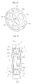
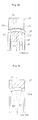
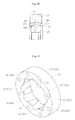
- the outer surface 24 of the inner race 26 is formed of a spherical surface, and the track grooves 25 thereof include, as illustrated in FIGS. 8 to 10 , track grooves 25a and 25b tilted in opposite directions from each other with respect to the axis line. That is, as illustrated in FIG. 9 , an axis line La1 of the first track groove 25a is tilted by the predetermined angle ⁇ with respect to a straight line L11 parallel to the joint axis line in a clockwise direction in FIG. 9 . An axis line Lb1 of the second track groove 25b is tilted by the predetermined angle ⁇ with respect to a straight line L12 parallel to the joint axis line in a counterclockwise direction in FIG. 9 . Note that, in the inner race 26, a shaft center hole 31 into which a shaft (not shown) is inserted is formed.
- the cage 28 includes pockets 29 in a circumferential wall thereof, for retaining the balls 27 at predetermined pitches in the circumferential direction.
- an outer surface of the circumferential wall is referred to as an outer spherical surface 28a
- an inner surface of the circumferential wall is referred to as an inner spherical surface 28b.
- a curvature center 03 of the outer spherical surface 28a coincides with a curvature center 04 of the inner spherical surface 28b.
- the curvature center 03 of the outer spherical surface 28a coincides with a curvature center of the inner surface of the outer race 23, and a curvature radius R3 of the outer spherical surface 28a is substantially the same as a radius of the inner surface of the outer race 23. Therefore, an axial intermediate portion of the outer spherical surface 28a is brought into contact with the inner surface of the outer race 23.
- the curvature center 04 of the inner spherical surface 28b coincides with the curvature center of the outer surface 24 of the inner race 26, and a curvature radius R4 of the inner spherical surface 28b is substantially the same as a curvature radius R5 (see FIG. 11 ) of the outer surface 24 of the inner race 26. Therefore, the inner spherical surface 28b of the cage 28 is brought into sliding contact with the entire outer surface 24 of the inner race 26.
- the outer race 23 and the inner race 26 are formed so that the track grooves 22a and 22b and the track grooves 25a and 25b, which are respectively tilted in opposite directions from each other with respect to the axis line, are alternately formed in the circumferential direction. Therefore, as illustrated in FIG. 16 , the track groove 22 of the outer race 23 and the track groove 25 of the inner race 26 are in a crossed state.
- the solid lines indicate the track grooves 22 of the outer race 23, and the two-dot chain lines indicate the track grooves 25 of the inner race 26.
- P1 represents a contact point of the ball 27 with respect to the track groove 22 of the outer race 23
- P2 represents a contact point of the ball 27 with respect to the track groove 25 of the inner race 26.
- the contact points P1 and P2 of the first track grooves 22a and 25a are shifted by a predetermined amount e toward one opening side from a plane S passing the joint center O and a ball center Ob of the ball 27 under a state in which the operating angle is not formed.
- the contact points P1 and P2 of the second track grooves 22b and 25b are shifted by the predetermined amount e toward another opening side from the plane S.
- the balls 27 adjacent to each other in the circumferential direction form wedge angles ⁇ in opposite directions from each other. That is, forces alternately act on adjacent pockets 29, and the wedge angles ⁇ and ⁇ ' in opposite directions arealternatelygenerated. Therefore, in the first track grooves 22a and 25a, a force W1 acts in a direction opposing to the contact points P1 and P2, and in the second track grooves 22b and 25b, a force W2 acts toward the contact points P1 and P2. Therefore, the cage position is stabilized at a median position of the inner and outer races.
- the cage 28 is required to be set in the outer race 23.
- the inner spherical surface 1 of the outer race 3 has a spherical surface shape
- an outer surface 8a and an inner surface 8b of the cage 8 has the spherical surface shape. Therefore, when the cage 8 is set in the outer race 3, as illustrated in FIG. 50 , the cage 8 is required to be inserted into the outer race 3 under a state in which an axial center of the cage 8 and an axial center of the outer race 3 are orthogonal to each other. That is, the holes of the pockets 9 of the cage 8 are used. Therefore, in the setting operation, it is necessary to perform phase alignment, which causes difficulty in the setting operation.
- insertion may be performed under a state in which an axial center of the outer race 23 coincides with an axial center of the cage 28 as indicated by the arrow. At this time, the insertion may be performed without considering the positional relationship between the track groove of the outer race 23 and the pocket 29 of the cage 28, and hence the setting operation can be facilitated.
- the outer spherical surface 28a of the cage 28 has little contact with the inner surface 21 of the outer race 23. Therefore, circulation of a lubricant agent is promoted, heat generation is prevented, and durability is improved. Further, it is unnecessary to perform finish working (grinding or hardened steel cutting) to the inner surface 21 of the outer race 23 and the outer spherical surface 28a of the cage 28. That is, the forged surfaces of the inner surface 21 of the outer race 23 and the outer spherical surface 28a of the cage 28 are not required to be processed. As described above, the finish working can be omitted, and hence cost reduction and improvement in productivity can be achieved. Note that, the track grooves 22 and 25 may be subjected to forge finishing, or mechanical working, that is, finish working (grinding or hardened steel cutting).
- FIG. 18 illustrates a fixed type constant velocity universal joint using an outer race 23 of a first modified example.
- the outer race 23 in this case is obtained by adding, to the outer race 23 illustrated in FIG. 1 , etc. (the outer race having the inner surface 21 with a cylindrical surface), tapered portions 21d and 21e provided at both opening portions and tapered toward each of the opening sides.
- a taper angle ⁇ (see FIG. 19 ) of the tapered portions 21d and 21e is set so that, when setting is performed as illustrated in FIG. 18 , the tapered portions 21d and 21e are not brought into contact with the outer spherical surface 28a of the cage 28. Therefore, the outer spherical surface 28a of the cage 28 has little contact with the inner surface 21 of the outer race 23.
- FIG. 20 illustrates the fixed type constant velocity universal joint using the outer race 23 of the first modified example.
- the inner surface 21 of the outer race 23 is a spherical surface 21a which forms a gap together with the outer spherical surface 28a of the cage 28.
- a curvature center O6 of the spherical surface 21a coincides with the curvature center 01 of the track groove 22.
- the inner race 26 of the fixed type constant velocity universal joint using this outer race 23 is configured so that a curvature center 05 of the outer surface 24 thereof coincides with the curvature center 04 of the inner spherical surface 28b of the cage 28, and a curvature radius R5 of the outer surface 24 substantially coincides with the curvature radius R4 of the inner spherical surface 28b. With this, the inner spherical surface 28b of the cage 28 and the outer surface 24 of the inner race 26 are brought into sliding contact with each other.
- FIG. 22 illustrates a fixed type constant velocity universal joint using an outer race 23 of a second modified example.
- the inner surface 21 of the outer race 23 in this case is an elliptical surface 21f which forms a gap together with the outer spherical surface 28a of the cage 28. That is, the elliptical surface 21f is formed along an oval sphere surface of an ellipse 32 indicated by the two-dot chain line in FIG. 23 .
- the inner race 26 of the fixed type constant velocity universal joint using this outer race 23 is configured so that a curvature center O5 of the outer surface 24 thereof coincides with the curvature center 04 of the inner spherical surface 28b of the cage 28, and the curvature radius R5 of the outer surface 24 substantially coincides with the curvature radius R4 of the inner spherical surface 28b. With this, the inner spherical surface 28b of the cage 28 and the outer surface 24 of the inner race 26 are brought into sliding contact with each other.
- the gap is formed between the inner surface 21 of the outer race 23 and the outer spherical surface 28a of the cage 28.
- the circulation of the lubricant agent is promoted, the heat generation is prevented, and the durability is improved.
- the inner spherical surface 28b of the cage 28 and the outer surface 24 of the inner race 26 are brought into sliding contact with each other. Therefore, the cage position is determined, and even in the case where there is no restriction of the cage 28 by the outer race 23, the function as the fixed type constant velocity universal joint can be stably exerted.
- the curvature center 01 of the track groove 22 of the outer race 23 and the curvature center 02 of the track groove 25 of the inner joint member are shifted from the joint center O in the radial direction.
- the curvature centers 01 and 02 are shifted by an offset amount H with respect to the joint center O at positions more widely spaced apart from the track groove than the joint center O.
- the curvature centers 01 and 02 are shifted by the offset amount H with respect to the joint center O at positions more approaching the track groove than the joint center O.
- FIG. 26 illustrates a case where the curvature center 01 of the outer race 23 is arranged at a position more widely spaced apart from the track groove than the joint center O, and a case where the curvature center 01 thereof is arranged at a position more approaching the track groove than the joint center O.
- O1a represents the curvature center of the track groove 22 of the outer race 23, which is arranged at a position more widely spaced apart from the track groove than the j oint center O
- O1b represents the curvature center of the track groove 22 of the outer race 23, which is arranged at a position more approaching the track groove than the joint center O.
- FIG. 27 illustrates a case where the curvature center 02 of the inner race 26 is arranged at a position more widely spaced apart from the track groove than the joint center O, and a case where the curvature center 02 is arranged at a position more approaching the track groove than the joint center O.
- 02a represents the curvature center of the track groove 25 of the inner race 26, which is arranged at a position more widely spaced apart from the track groove than the joint center O
- 02b represents the curvature center of the track groove 25 of the inner race 26, which is arranged at a position more approaching the track groove than the joint center O.
- the track groove 22 of the outer race 23 can be taken large.
- a load capacity thereof can be increased, and a thickness of an axial end opening portion of the track groove 25 of the inner race 26 can be increased, to thereby enable stable connection of the shaft to be fitted into the hole portion of the inner race 26.
- t0 represents a thickness of the outer race at an axial end portion of the track groove 22 when the curvature center 01 of the track groove 22 coincides with the joint center
- t2 represents a thickness of the outer race at the axial end portion of the track groove 22 when the curvature center 01 of the track groove 22 is displaced in a directionmore approaching the track groove than the joint center O.
- t10 represents a thickness of the inner race at an axial end portion of the track groove 25 when the curvature center 02 of the track groove 25 coincides with the joint center O
- t11 represents a thickness of the inner race at the axial end portion of the track groove 25 when the curvature center 02 of the track groove 25 is more widely spaced apart from the track groove than the joint center O.
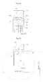
- the inner surface 21 of the outer race 23 is a spherical surface, and as illustrated in FIG. 36 , the outer surface 24 of the inner race 26 is a cylindrical surface. Therefore, as illustrated in FIG. 30 , a gap is formed between the outer surface 24 of the inner race 26 and the inner spherical surface 28b of the cage 28. Further, the curvature center of the inner surface 21 of the outer race 23 coincides with the curvature center 01 of the track groove 22 of the outer race 23. Note that, as illustrated in FIG. 32 , cutout portions 21b and 21c are provided at both axial end portions of the inner surface 21 of the outer race 23.
- the track grooves 22 include track grooves 22a and 22b that are tilted in opposite directions from each other with respect to the axis line. That is, as illustrated in FIG. 34 , the axis line La of the first track groove 22a is tilted by the predetermined angle ⁇ with respect to the straight line L1 parallel to the joint axis line in the counterclockwise direction of FIG. 34 . The axis line Lb of the second track groove 22b is tilted by the predetermined angle ⁇ with respect to the straight line L2 parallel to the joint axis line in the clockwise direction of FIG. 34 .
- the track grooves 25 of the inner race 26 include track grooves 25a and 25b that are tilted in opposite directions from each other with respect to the axis line. That is, as illustrated in FIG. 38 , the axis line La1 of the first track groove 25a is tilted by the predetermined angle ⁇ with respect to the straight line L11 parallel to the joint axis line in the clockwise direction of FIG. 38 . The axis line Lb1 of the second track groove 25b is tilted by the predetermined angle ⁇ with respect to the straight line L12 parallel to the joint axis line in the counterclockwise direction of FIG. 38 . Note that, in the inner race 26, the shaft center hole 31 into which the shaft (not shown) is fitted is formed.
- the track grooves 22a and 22b of the outer race 23 and the track grooves 25a and 25b of the inner race 26 have a relationship as illustrated in FIGS. 15 and 16 .
- the fixed type constant velocity universal joint which includes the inner race 26 having the outer surface 24 being a cylindrical surface
- the fixed type constant velocity universal joint which includes the outer race 23 having the inner surface being a cylindrical surface
- the inner race 26 is required to be set in the cage 28.
- the outer spherical surface 4 of the inner race 6 has a spherical surface shape, and also an inner surface of the cage 8 has the spherical surface shape. Therefore, when the inner race 6 is set in the cage 8, the inner race 6 is required to be inserted into the cage 8 under a state in which the axial center of the cage 8 and the axial center of the inner race 6 are orthogonal to each other. That is, the recesses of the track grooves 5 of the inner race 6 are used. Therefore, in the setting operation, it is necessary to perform phase alignment, which causes difficulty in the setting operation.
- the outer surface 24 of the inner race 26 is a cylindrical surface
- insertion may be performed under a state in which an axial center of the inner race 26 coincides with the axial center of the cage 28 as indicated by the arrow.
- the insertion may be performed without considering the positional relationship between the track groove 25 of the inner race 26 and the pocket 29 of the cage 28, and hence the setting operation can be facilitated.
- the outer surface 24 of the inner race 26 is a cylindrical surface, and hence the setting property of the inner race 26 into the cage 28 and workability of the inner race 26 can be improved.
- the inner spherical surface 28b of the cage 28 is a concave spherical surface, and hence the outer surface 24 of the inner race 26 and the inner spherical surface 28b of the cage 28 have little contact with each other. Therefore, lubrication by a lubricant agent is promoted, heat generation is prevented, and durability is improved.
- the inner surface 21 of the outer race 23 is a spherical surface which is to be brought into sliding contact with the outer spherical surface 28a of the cage 28. In this manner, the cage position is determined. Therefore, even in the case where there is no restriction of the cage 28 by the inner race 26, the function as the fixed type constant velocity universal joint can be stably exerted.
- the inner spherical surface 28b of the cage 28 has little contact with the outer surface 21 of the inner race 26. Therefore, circulation of a lubricant agent is promoted, heat generation is prevented, and durability is improved. Further, it is unnecessary to perform finish working (grinding or hardened steel cutting) to the outer surface 24 of the inner race 26 and the inner spherical surface 28b of the cage 28. That is, the forged surfaces of the outer surface 24 of the inner race 26 and the inner spherical surface 28b of the cage 28 are not required to be processed. As described above, the finish working can be omitted, and hence cost reduction and improvement in productivity can be achieved. Note that, the track grooves 22 and 25 may be subjected to forge finishing, or mechanical working, that is, finish working (grinding or hardened steel cutting).
- FIG. 40 illustrates a fixed type constant velocity universal joint using an inner race 26 of a first modified example.
- the outer surface 24 of the inner race 26 is a spherical surface 24a which forms a gap together with the inner spherical surface 28b of the cage 28.
- the curvature center O5 of the spherical surface 24a coincides with the curvature center 02 of the track groove 25.
- the outer race 23 of the fixed type constant velocity universal joint using this inner race 26 is configured so that, as illustrated in FIG. 40 , the curvature center 06 of the inner surface 21 thereof coincides with the curvature center 03 of the outer spherical surface 28a of the cage 28, and a curvature radius R6 of the inner surface 21 substantially coincides with the curvature radius R3 of the outer spherical surface 28a.
- the outer spherical surface 28a of the cage 28 and the inner surface 21 of the outer race 23 are brought into sliding contact with each other.
- the cutout portions 21b and 21c are provided at both the axial end portions of the inner surface 21 of the outer race 23.
- FIG. 42 illustrates a fixed type constant velocity universal joint using an inner race 26 of a second modified example.
- the outer surface 24 of the inner race 26 is an elliptical surface 24b which forms a gap together with the inner spherical surface 28b of the cage 28. That is, the elliptical surface 24b is formed along an oval sphere surface of an ellipse 52 indicated by the two-dot chain line in FIG. 43 .
- the outer race 23 of the fixed type constant velocity universal joint using this inner race 26 is configured so that the curvature center 06 of the inner surface 21 thereof coincides with the curvature center 03 of the outer spherical surface 28a of the cage 28, and the curvature radius R6 of the inner surface 21 substantially coincides with the curvature radius R3 of the outer spherical surface 28a. With this, the outer spherical surface 28a of the cage 28 and the inner surface 21 of the outer race 23 are brought into sliding contact with each other.
- the gap is formed between the outer surface 24 (24b) of the inner race 26 and the inner spherical surface 28b of the cage 28.
- the circulation of the lubricant agent is promoted, the heat generation is prevented, and the durability is improved.
- the outer spherical surface 28a of the cage 28 and the inner surface 21 of the outer race 23 are brought into sliding contact with each other. Therefore, the cage position is determined, and even in the case where there is no restriction of the cage 28 by the inner race 26, the function as the fixed type constant velocity universal joint can be stably exerted.
- the curvature center 01 of the track groove 22 of the outer race 23 and the curvature center 02 of the track groove 25 of the inner joint member are shifted from the joint center O in the radial direction.
- the curvature centers 01 and 02 are shifted by the offset amount H with respect to the joint center O at positions more widely spaced apart from the track groove than the joint center O.
- the curvature centers 01 and 02 are shifted by the offset amount H with respect to the joint center 0 at positions more approaching the track groove than the joint center O.
- FIG. 46 illustrates a case where the curvature center 01 of the outer race 23 is arranged at a position more widely spaced apart from the track groove than the joint center O, and a case where the curvature center O1 thereof is arranged at a position more approaching the track groove than the joint center O.
- O1a represents the curvature center of the track groove 22 of the outer race 23, which is arranged at a position more widely spaced apart from the track groove than the joint center O
- O1b represents the curvature center of the track groove 22 of the outer race 23, which is arranged at a position more approaching the track groove than the joint center O.
- FIG. 47 illustrates a case where the curvature center 02 of the inner race 26 is arranged at a position more widely spaced apart from the track groove than the joint center O, and a case where the curvature center 02 is arranged at a position more approaching the track groove than the joint center O.
- 02a represents the curvature center of the track groove 25 of the inner race 26, which is arranged at a position more widely spaced apart from the track groove than the joint center O
- 02b represents the curvature center of the track groove 25 of the inner race 26, which is arranged at a position more approaching the track groove than the joint center O.
- t0 represents the thickness of the outer race at the axial end portion of the track groove 22 when the curvature center O1 of the track groove 22 coincides with the joint center O
- t2 represents the thickness of the outer race at the axial end portion of the track groove 22 when the curvature center 01 of the track groove 22 is more approaching the track groove than the joint center O.
- t10 represents the thickness of the inner race at the axial end portion of the track groove 25 when the curvature center O2 of the track groove 25 coincides with the joint center O
- t11 represents the thickness of the inner race at the axial end portion of the track groove 25 when the curvature center 02 of the track groove 25 is more widely spaced apart from the track groove than the joint center O.
- the present invention is not limited to the embodiments described above, and various modifications can be made thereto.
- the present invention is not limited to the following cases where: the curvature center 01 of the track groove 22 of the outer race 23 and the curvature center 02 of the track groove 25 of the inner joint member are shifted from the joint center 0 in the radial direction; the inner surface 21 of the outer race 23 is a cylindrical surface; and the outer surface 24 of the inner race 26 is a cylindrical surface.
- the number of balls is eight in the respective embodiments, but may be other than eight, for example, six or ten.
- the fixed type constant velocity universal joint of the present invention is used in a power transmission system for automobiles and various industrial machines.
- the number of balls as a torque transmitting member is six, eight, ten, etc.
- the fixed type constant velocity universal joint of the present invention may be used in a propeller shaft for automobiles.
Landscapes
- Engineering & Computer Science (AREA)
- General Engineering & Computer Science (AREA)
- Mechanical Engineering (AREA)
- Rolling Contact Bearings (AREA)
- Pivots And Pivotal Connections (AREA)
Abstract
Description
- The present invention relates to a constant velocity universal joint which is used in, for example, a power transmission system for automobiles and various industrial machines.
- For example, a fixed type constant velocity universal joint can be taken as an example of a constant velocity universal joint used as means for transmitting a rotational force from an engine to wheels of an automobile at a constant velocity. The fixed type constant velocity universal joint has a structure in which two shafts, a driving shaft and a driven shaft, are coupled to each other and which is capable of transmitting rotational torque at a constant velocity even when the two shafts form an operating angle. Generally, a Birfield type (BJ) constant velocity universal joint and an undercut-free type (UJ) constant velocity universal joint have been widely known as the above-mentioned constant velocity universal joint.
- As illustrated in
FIG. 48 , the fixed type constant velocity universal joint of the BJ type includes: anouter race 3 having an innerspherical surface 1 in which a plurality oftrack grooves 2 are equiangularly formed along an axial direction, theouter race 3 serving as an outer joint member; aninner race 6 having an outerspherical surface 4 in which a plurality oftrack grooves 5 are equiangularly formed in pairs with thetrack grooves 2 of theouter race 3 along the axial direction, theinner race 6 serving as an inner joint member; a plurality ofballs 7 interposed between thetrack grooves 2 of theouter race 3 and thetrack grooves 5 of theinner race 6, for transmitting torque; and acage 8 interposed between the innerspherical surface 1 of theouter race 3 and the outerspherical surface 4 of theinner race 6, for retaining theballs 7. In thecage 8, a plurality ofpockets 9 for housing theballs 7 are arranged along a circumferential direction. - At an inner surface of a hole portion of the
inner race 6, afemale spline 10 is formed. Amale spline 12 of ashaft 11 is fitted into the hole portion of theinner race 6, to thereby fit themale spline 12 to thefemale spline 10 of theinner race 6. Then, astop ring 13 for preventing dropping is fitted to an end portion of themale spline 12. - In order to close an opening portion of the
outer race 3, anend cap 15 and aflexible boot 16 are mounted. Theflexible boot 16 is formed of abellow 18 made of a rubber material or a resin material, and acylindrical adapter 19 made of a metal. Thebellow 18 includes a smalldiameter end portion 18a fitted onto theshaft 11, a largediameter end portion 18b connected to theadapter 19, and abent portion 18c provided between the smalldiameter end portion 18a and the largediameter end portion 18b. The smalldiameter end portion 18a of thebellow 18 is fixed to theshaft 11 by being fastened by aband 20. Theadapter 19 includes aswage portion 19a swaged and fixed to the largediameter end portion 18b of thebellow 18, and anannular flange portion 19b fitted to theouter race 3. Note that, theend cap 15 includes amain body portion 15a as a bottomed short cylindrical member, and anannular flange portion 15b fitted to theouter race 3. - Further, a
curvature center 02 of each of thetrack grooves 5 of theinner race 6 is shifted from a joint center O on the end cap side in the axial direction. Further, acurvature center 01 of each of thetrack grooves 2 of theouter race 3 is shifted from the joint center O on the flexible boot side in the axial direction. That is, thecurvature center 02 of thetrack groove 5 of theinner race 6 and thecurvature center 01 of thetrack groove 2 of theouter race 3 are offset to opposite sides in the axial direction by equal distances F and F with respect to the joint center O. - Conventionally, there has been proposed an 8-ball constant velocity universal joint (Patent Literature 1) in which the ball diameter is reduced for the purpose of achieving high performance and reducing the size, so as to suppress reduction in load capacity per one ball. Further, there are proposals of forming the tracks of the inner and outer races into a spiral form or tilting the tracks in the axial direction, to thereby set the adjacent tracks to be plane-symmetrical. Thus, the contact force between the ball and the track portion of the inner or outer race can be reduced, thereby enhancing durability (Patent Literature 2).
-
- Patent Literature 1:
JP 3859264 B - Patent Literature 2:
JP 3300663 B - In the constant velocity universal joint described in
Patent Literature 1 above, in order to enable thecage 8 to smoothly operate, as described above, thecurvature center 02 of thetrack groove 5 of theinner race 6 and the curvature center O1 of thetrack groove 2 of theouter race 3 are offset to opposite sides in the axial direction by equal distances F and F with respect to the joint center O. Therefore, as illustrated inFIG. 49 , theball 7 forms a wedge angle τ under a state in which theball 7 is sandwiched between the tracks of the inner and outer races (ball track which is formed of thetrack groove 5 of theinner race 6 and thetrack groove 2 of theouter race 3 and in which the ball is interposed). The wedge angle τ enables theball 7 to push thepocket 9, and thus thecage 8 is operated smoothly. Note that, inFIG. 49 , P1 represents a contact point of theball 7 with respect to thetrack groove 2 of theouter race 3, and P2 represents a contact point of theball 7 with respect to thetrack groove 5 of theinner race 6. - As described above, the offset (track offset) is important in order to operate the
cage 8, but as illustrated inFIG. 49 , a force W is applied only in a direction of an opening portion of the joint, and hence inner and outerspherical surfaces spherical surface 1 of theouter race 3 and the outerspherical surface 4 of theinner race 6. Therefore, when the joint is subjected to high load or rotated at high speed, this contact causes heat generation in the joint, and the durability may reduce. - Further, also in the constant velocity universal joint described in
Patent Literature 2 above, in addition to the track offset, the tracks of the inner and outer races are formed into a spiral form or tilted in the axial direction, to thereby reduce the ball contact force to the tracks of the inner and outer races and further reduce the force to be applied to the cage. However, even with such a structure, when the joint is subjected to high load or during high-speed rotation, heat may be generated due to the contact between the inner spherical surfaces of the cage and the outer spherical surface of the inner race or the outer spherical surfaces of the cage and the inner spherical surface of the outer race, which may decrease the durability. - In view of the circumstances as described above, the present invention provides a fixed type constant velocity universal joint, which is capable of preventing heat generation when high load is applied or during high-speed rotation to improve the durability, and further, suppressing a contact resistance between the cage and the inner and outer races to improve the constant velocity performance.
- A first fixed type constant velocity universal joint according to the present invention includes: an outer joint member including an inner surface provided with a track groove having a bottom surface being a circular arc surface; an inner joint member including an outer surface provided with a track groove having a bottom surface being a circular arc surface; a plurality of torque transmitting balls each arranged in a ball track formed of a pair of the track groove of the outer joint member and the track groove of the inner joint member; and a cage interposed between the inner surface of the outer joint member and the outer surface of the inner joint member, for retaining the plurality of torque transmitting balls. A curvature center of the track groove of the outer joint member and a curvature center of the track groove of the inner joint member have an offset of 0 in an axial direction. The track groove of the outer joint member and the track groove of the inner joint member, which are tilted in opposite directions from each other with respect to an axis line, are alternately formed in a circumferential direction. The outer surface of the inner joint member is a spherical surface which is to be brought into sliding contact with an inner spherical surface of the cage, and the inner surface of the outer joint member is a cylindrical surface.
- Further, in the first fixed type constant velocity universal joint, the inner surface of the outer joint member may include an opening portion having a tapered portion toward an opening side.
- A second fixed type constant velocity universal joint according to the present invention includes: an outer joint member including an inner surface provided with a track groove having a bottom surface being a circular arc surface; an inner joint member including an outer surface provided with a track groove having a bottom surface being a circular arc surface; a plurality of torque transmitting balls each arranged in a ball track formed of a pair of the track groove of the outer joint member and the track groove of the inner joint member; and a cage interposed between the inner surface of the outer joint member and the outer surface of the inner joint member, for retaining the plurality of torque transmitting balls. A curvature center of the track groove of the outer joint member and a curvature center of the track groove of the inner joint member have an offset of 0 in an axial direction. The track groove of the outer joint member and the track groove of the inner joint member, which are tilted in opposite directions from each other with respect to an axis line, are alternately formed in a circumferential direction. The outer surface of the inner joint member is a spherical surface which is to be brought into sliding contact with an inner spherical surface of the cage, and the inner surface of the outer joint member is a spherical surface which forms a gap together with an outer spherical surface of the cage.
- A third fixed type constant velocity universal joint according to the present invention includes: an outer joint member including an inner surface provided with a track groove having a bottom surface being a circular arc surface; an inner joint member including an outer surface provided with a track groove having a bottom surface being a circular arc surface; a plurality of torque transmitting balls each arranged in a ball track formed of a pair of the track groove of the outer joint member and the track groove of the inner joint member; and a cage interposed between the inner surface of the outer joint member and the outer surface of the inner joint member, for retaining the plurality of torque transmitting balls. A curvature center of the track groove of the outer joint member and a curvature center of the track groove of the inner joint member have an offset of 0 in an axial direction. The track groove of the outer joint member and the track groove of the inner joint member, which are tilted in opposite directions from each other with respect to an axis line, are alternately formed in a circumferential direction. The outer surface of the inner joint member is a spherical surface which is to be brought into sliding contact with an inner spherical surface of the cage, and the inner surface of the outer joint member is an elliptical surface which forms a gap together with an outer spherical surface of the cage.
- A fourth fixed type constant velocity universal joint according to the present invention includes: an outer joint member including an inner surface provided with a track groove having a bottom surface being a circular arc surface; an inner joint member including an outer surface provided with a track groove having a bottom surface being a circular arc surface; a plurality of torque transmitting balls each arranged in a ball track formed of a pair of the track groove of the outer joint member and the track groove of the inner joint member; and a cage interposed between the inner surface of the outer joint member and the outer surface of the inner joint member, for retaining the plurality of torque transmitting balls. A curvature center of the track groove of the outer joint member and a curvature center of the track groove of the inner joint member have an offset of 0 in an axial direction. The track groove of the outer joint member and the track groove of the inner joint member, which are tilted in opposite directions from each other with respect to an axis line, are alternately formed in a circumferential direction. The inner surface of the outer joint member is a spherical surface which is to be brought into sliding contact with an outer spherical surface of the cage, and the outer surface of the inner joint member is a cylindrical surface.
- A fifth fixed type constant velocity universal joint according to the present invention includes: an outer joint member including an inner surface provided with a track groove having a bottom surface being a circular arc surface; an inner joint member including an outer surface provided with a track groove having a bottom surface being a circular arc surface; a plurality of torque transmitting balls each arranged in a ball track formed of a pair of the track groove of the outer joint member and the track groove of the inner joint member; and a cage interposed between the inner surface of the outer joint member and the outer surface of the inner joint member, for retaining the plurality of torque transmitting balls. A curvature center of the track groove of the outer joint member and a curvature center of the track groove of the inner joint member have an offset of 0 in an axial direction. The track groove of the outer joint member and the track groove of the inner joint member, which are tilted in opposite directions from each other with respect to an axis line, are alternately formed in a circumferential direction. The inner surface of the outer joint member is a spherical surface which is to be brought into sliding contact with an outer spherical surface of the cage, and the outer surface of the inner joint member is a spherical surface which forms a gap together with an inner spherical surface of the cage.
- A sixth fixed type constant velocity universal joint according to the present invention includes: an outer joint member including an inner surface provided with a track groove having a bottom surface being a circular arc surface; an inner joint member including an outer surface provided with a track groove having a bottom surface being a circular arc surface; a plurality of torque transmitting balls each arranged in a ball track formed of a pair of the track groove of the outer joint member and the track groove of the inner joint member; and a cage interposed between the inner surface of the outer joint member and the outer surface of the inner joint member, for retaining the plurality of torque transmitting balls. A curvature center of the track groove of the outer joint member and a curvature center of the track groove of the inner joint member have an offset of 0 in an axial direction. The track groove of the outer joint member and the track groove of the inner joint member, which are tilted in opposite directions from each other with respect to an axis line, are alternately formed in a circumferential direction. The inner surface of the outer joint member is a spherical surface which is to be brought into sliding contact with an outer spherical surface of the cage, and the outer surface of the inner joint member is an elliptical surface which forms a gap together with an inner spherical surface of the cage.
- According to the fixed type constant velocity universal joint of the present invention, the track offset is set to 0, and the adjacent track grooves are alternately intersected. Thus, forces alternately act on adjacent pocket portions, and hence wedge angles in opposite directions are alternately generated. Therefore, a cage position is stabilized at a median position of the inner and outer races.
- When the inner surface of the outer joint member is a cylindrical surface as in the first fixed type constant velocity universal joint, setting property of the cage into the outer joint member and workability of the outer joint member can be improved. Further, the outer spherical surface of the cage is a convex spherical surface, and hence the inner surface of the outer joint member and the outer spherical surface of the cage have little contact with each other.
- When the inner surface of the outer joint member is a spherical surface which forms a gap together with the outer spherical surface of the cage as in the second fixed type constant velocity universal joint, and when the inner surface of the outer joint member is an elliptical surface which forms a gap together with the outer spherical surface of the cage as in the third fixed type constant velocity universal joint, lubrication by a lubricant agent is promoted.
- Further, when the outer surface of the inner joint member is a spherical surface which is to be brought into sliding contact with the inner spherical surface of the cage as in the first to third fixed type constant velocity universal joints, the cage position is determined.
- When the outer surface of the inner joint member is a cylindrical surface as in the fourth fixed type constant velocity universal joint, setting property of the inner joint member into the cage and workability of the inner joint member can be improved. Further, the inner spherical surface of the cage is a concave spherical surface, and hence the outer surface of the inner joint member and the inner spherical surface of the cage have little contact with each other.
- When the outer surface of the inner joint member is a spherical surface which forms a gap together with the inner spherical surface of the cage as in the fifth fixed type constant velocity universal joint, and when the outer surface of the inner joint member is an elliptical surface which forms a gap together with the inner spherical surface of the cage as in the sixth fixed type constant velocity universal joint, lubrication by a lubricant agent is promoted.
- Further, when the inner surface of the outer joint member is a spherical surface which is to be brought into sliding contact with the outer spherical surface of the cage as in the fourth to sixth fixed type constant velocity universal joints, the cage position is determined.
- In the first to third fixed type constant velocity universal joints, finish working of the inner surface of the outer joint member may be omitted. Further, the inner surface of the outer joint member may be formed by forging, and further, finish working of an outer surface of the cage may be omitted.
- In the fourth to sixth fixed type constant velocity universal joints, finish working of the outer surface of the inner joint member may be omitted. Further, the outer surface of the inner joint member may be formed by forging, and further, finish working of an inner surface of the cage may be omitted.
- In the above-mentioned fixed type constant velocity universal joints, the track groove may be formed by forging, or may be formed by mechanical working.
- In the above-mentioned fixed type constant velocity universal joints, a number of the plurality of torque transmitting balls may be selected among six, eight, and ten.
- In the above-mentioned fixed type constant velocity universal joints, the curvature center of the track groove of the outer joint member and the curvature center of the track groove of the inner joint member may be shifted from a joint center in a radial direction. In this case, the curvature center of the track groove of the outer joint member can be displaced in a direction more widely spaced apart from the track groove than the joint center, and the curvature center of the track groove of the outer joint member can be displaced in a direction more approaching the track groove than the joint center.
- The above-mentioned fixed type constant velocity universal joints may be used in a propeller shaft for an automobile.
- In the fixed type constant velocity universal joint according to the present invention, forces alternately act on adjacent pocket portions, and hence wedge angles in opposite directions are alternately generated. Therefore, the cage position is stabilized at a median position of the inner and outer races. Therefore, the spherical surface contact of the outer and inner spherical surfaces of the cage is suppressed, and it is possible to smoothly operate the joint even when high load is applied or during high-speed rotation, prevent heat generation, and improve the durability.
- When the inner surface of the outer joint member is a cylindrical surface as in the first fixed type constant velocity universal joint, setting property of the cage into the outer joint member and workability can be improved. Thus, the production cost can be reduced and the productivity can be improved.
- When the inner surface of the outer joint member forms a gap together with the outer spherical surface of the cage as in the second fixed type constant velocity universal joint and the third fixed type constant velocity universal joint, circulation of a lubricant agent is promoted, heat generation is prevented, and durability is improved.
- Further, when the outer surface of the inner joint member is a spherical surface which is to be brought into sliding contact with the inner spherical surface of the cage as in the first to third fixed type constant velocity universal joints, the cage position is determined. Even in a case where there is no restriction of the cage by the outer joint member, the function as the fixed type constant velocity universal joint can be stably exerted.
- In the second fixed type constant velocity universal joint and the third fixed type constant velocity universal joint, the inner surface of the outer joint member does not contact to the outer spherical surface of the cage, and in the first fixed type constant velocity universal joint, a contact area is small even when the inner surface of the outer joint member is brought into contact with the outer spherical surface of the cage. Therefore, in those fixed type constant velocity universal joints, the inner surface of the outer joint member and the outer spherical surface of the cage do not need to be subjected to high accuracy working such as grinding after heat treatment or hardened steel cutting. Thus, the cost can be reduced.
- When the outer surface of the inner joint member is a cylindrical surface as in the fourth fixed type constant velocity universal joint, setting property of the inner joint member into the cage and workability of the inner joint member can be improved. Thus, the production cost can be reduced and the productivity can be improved,
- When the outer surface of the inner joint member forms a gap together with the inner spherical surface of the cage as in the fifth fixed type constant velocity universal joint and the sixth fixed type constant velocity universal joint, lubrication by a lubricant agent is promoted, heat generation is prevented, and durability is improved.
- When the inner surface of the outer joint member is a spherical surface which is to be brought into sliding contact with the outer spherical surface of the cage as in the fourth to sixth fixed type constant velocity universal joints, the cage position is determined. Even in a case where there is no restriction of the cage by the inner joint member, the function as the fixed type constant velocity universal joint can be stably exerted.
- In the fifth fixed type constant velocity universal joint and the sixth fixed type constant velocity universal joint, the outer surface of the inner joint member does not contact to the inner spherical surface of the cage, and in the fourth fixed type constant velocity universal joint, a contact area is small even when the outer surface of the inner joint member is brought into contact with the inner spherical surface of the cage. Therefore, in those fixed type constant velocity universal joints, the outer surface of the inner joint member and the inner spherical surface of the cage do not need to be subjected to high accuracy working such as grinding after heat treatment or hardened steel cutting. Thus, the cost can be reduced and the productivity can be improved.
- The number of balls to be used is generally six, but the present invention is also applicable to a fixed type constant velocity universal joint using eight or ten balls. When the number of balls is increased as described above, the joint can be reduced in size and weight while securing the load capacity.
- When the curvature centers of the track grooves of the outer joint member and the inner joint member are displaced in a direction more widely spaced apart from the track groove than the joint center, the track groove of the outer joint member can be taken large (deep). Therefore, the load capacity can be increased, and a thickness of an axial end opening portion of the track groove of the inner joint member can be increased, to thereby enable stable connection of the shaft to be fitted into a hole portion of the inner joint member. Further, when the curvature centers of the track grooves of the outer joint member and the inner joint member are displaced in a direction more approaching the track groove than the joint center O, a load capacity of the track groove of the inner joint member can be increased, and the thickness of the outer joint member can be increased. Thus, the strength is stabilized.
- In the fixed type constant velocity universal joint according to the present invention, it is possible to smoothly operate the joint even when high load is applied or during high-speed rotation, prevent heat generation, and improve the durability. Therefore, the present invention is suitable for a fixed type constant velocity universal joint used in a propeller shaft for automobiles.
-
- [
FIG. 1 ] A front view of a fixed type constant velocity universal joint, illustrating a first embodiment of the present invention. - [
FIG. 2 ] A sectional view taken along the line A-O-B ofFIG. 1 . - [
FIG. 3 ] A sectional view of a main part of the fixed type constant velocity universal joint. - [
FIG. 4 ] A front view of an outer race of the fixed type constant velocity universal joint. - [
FIG. 5 ] A sectional view taken along the line Y-Y ofFIG. 4 . - [
FIG. 6 ] A perspective view of the outer race of the fixed type constant velocity universal joint. - [
FIG. 7 ] A sectional view of a main part of the outer race of the fixed type constant velocity universal joint. - [
FIG. 8 ] A front view of an inner race of the fixed type constant velocity universal joint. - [
FIG. 9 ] An arrow view in the Z direction ofFIG. 8 . - [
FIG. 10 ] A perspective view of the inner race of the fixed type constant velocity universal joint. - [
FIG. 11 ] A sectional view of the inner race of the fixed type constant velocity universal joint. - [
FIG. 12 ] A front view of a cage of the fixed type constant velocity universal joint. - [
FIG. 13 ] A sectional view of the cage of the fixed type constant velocity universal joint. - [
FIG. 14 ] A perspective view of the cage of the fixed type constant velocity universal joint. - [
FIG. 15 ] A sectional view of the fixed type constant velocity universal joint in a state in which torque load is applied. - [
FIG. 16 ] A schematic exploded view of the fixed type constant velocity universal joint in the state in which torque load is applied. - [
FIG. 17 ] A perspective view illustrating a method of inserting the cage into the outer race. - [
FIG. 18 ] A sectional view of a main part of a fixed type constant velocity universal joint using an outer race of a first modified example. - [
FIG. 19 ] A sectional view of a main part of the outer race of the fixed type constant velocity universal joint inFIG. 18 . - [
FIG. 20 ] A sectional view of a main part of a fixed type constant velocity universal joint using an outer race of a second modified example. - [
FIG. 21 ] A sectional view of a main part of the outer race of the fixed type constant velocity universal joint inFIG. 20 . - [
FIG. 22 ] A sectional view of a main part of a fixed type constant velocity universal joint using an outer race of a third modified example. - [
FIG. 23 ] A sectional view of a main part of the outer race of the fixed type constant velocity universal joint inFIG. 22 . - [
FIG. 24 ] A front view of a fixed type constant velocity universal joint, illustrating a second embodiment of the present invention. - [
FIG. 25 ] A front view of a fixed type constant velocity universal joint, illustrating a third embodiment of the present invention. - [
FIG. 26 ] A sectional view of the outer race under a state in which a curvature center of a track groove is offset in a radial direction. - [
FIG. 27 ] A sectional view of the inner race under a state in which a curvature center of a track groove is offset in a radial direction. - [
FIG. 28 ] A front view of a fixed type constant velocity universal joint, illustrating a fourth embodiment of the present invention. - [
FIG. 29 ] A sectional view taken along the line A'-O-B' ofFIG. 28 . - [
FIG. 30 ] An enlarged sectional view of a main part of the fixed type constant velocity universal joint inFIG. 28 . - [
FIG. 31 ] A perspective view of an outer race of the fixed type constant velocity universal joint inFIG. 28 . - [
FIG. 32 ] A sectional view of the outer race of the fixed type constant velocity universal joint inFIG. 28 . - [
FIG. 33 ] A front view of the outer race of the fixed type constant velocity universal joint inFIG. 28 . - [
FIG. 34 ] A sectional view taken along the line Y'-Y' ofFIG. 33 . - [
FIG. 35 ] A perspective view of an inner race of the fixed type constant velocity universal joint inFIG. 28 . - [
FIG. 36 ] A sectional view of the inner race of the fixed type constant velocity universal joint inFIG. 28 . - [
FIG. 37 ] A front view of the inner race of the fixed type constant velocity universal joint inFIG. 28 . - [
FIG. 38 ] An arrow view in the Z' direction ofFIG. 37 . - [
FIG. 39 ] A perspective view illustrating a method of inserting the inner race into the cage. - [
FIG. 40 ] A sectional view of a main part of a fixed type constant velocity universal joint using an inner race of a first modified example. - [
FIG. 41 ] A sectional view of the inner race of the fixed type constant velocity universal joint inFIG. 40 . - [
FIG. 42 ] A sectional view of a main part of a fixed type constant velocity universal joint using an inner race of a second modified example. - [
FIG. 43 ] A sectional view of the inner race of the fixed type constant velocity universal joint inFIG. 42 . - [
FIG. 44 ] A sectional view of a fixed type constant velocity universal joint, illustrating a fifth embodiment of the present invention. - [
FIG. 45 ] A sectional view of a fixed type constant velocity universal joint, illustrating a sixth embodiment of the present invention. - [
FIG. 46 ] A sectional view of the outer race under a state in which a curvature center of a track groove is offset in a radial direction. - [
FIG. 47 ] A sectional view of the inner race under a state in which a curvature center of a track groove is offset in a radial direction. - [
FIG. 48 ] A sectional view of a conventional fixed type constant velocity universal joint. - [
FIG. 49 ] An enlarged sectional view of a main part of the fixed type constant velocity universal joint inFIG. 48 . - [
FIG. 50 ] A perspective view illustrating a conventional method of inserting a cage into an outer race. - [
FIG. 51 ] A perspective view illustrating a conventional method of inserting an inner race into a cage. - Hereinafter, embodiments of the present invention are described with reference to
FIGS. 1 to 47 . - A fixed type constant velocity universal joint according to a first embodiment of the present invention includes, as illustrated in
FIGS. 1 and 2 : anouter race 23 having aninner surface 21 in which a plurality of (eight)track grooves 22 are formed along an axial direction, theouter race 23 serving as an outer joint member; aninner race 26 having anouter surface 24 in which a plurality of (eight)track grooves 25 are formed along the axial direction, theinner race 26 serving as an inner joint member; a plurality of (eight)torque transmitting balls 27 arranged in ball tracks formed of pairs of thetrack grooves 22 of theouter race 23 and thetrack grooves 25 of theinner race 26; and acage 28 interposed between the inner surface of theouter race 23 and the outer surface of the inner race, for retaining the torque transmitting balls. - Each of the
track grooves 22 of theouter race 23 has a track groove bottom which is only formed of a circular arc portion, and acurvature center 01 thereof coincides with a joint center O. Further, each of thetrack grooves 25 of theinner race 26 has a track groove bottom which is only formed of a circular arc portion, and acurvature center 02 thereof coincides with the joint center O. That is, unlike a conventional fixed type constant velocity universal joint illustrated inFIG. 48 , thetrack groove 22 of theouter race 23 and thetrack groove 25 of theinner race 26 are not offset in the axial direction. - Further, as illustrated in
FIGS. 3 and7 , theinner surface 21 of theouter race 23 is formed of a cylindrical surface, and thetrack grooves 22 thereof include, as illustrated inFIGS. 4 to 6 ,track grooves FIG. 5 , an axis line La of thefirst track groove 22a is tilted by a predetermined angle γ with respect to a straight line L1 parallel to the joint axis line in a counterclockwise direction inFIG. 5 . An axis line Lb of thesecond track groove 22b is tilted by the predetermined angle γ with respect to a straight line L2 parallel to the joint axis line in a clockwise direction inFIG. 5 . Note that, theouter race 23 is provided with throughholes 30 arranged at predetermined pitches along a circumferential direction. The through holes 30 are provided for, as in the conventional fixed type constant velocity universal joint, mounting an end cap or a flexible boot to theouter race 23. - The
outer surface 24 of theinner race 26 is formed of a spherical surface, and thetrack grooves 25 thereof include, as illustrated inFIGS. 8 to 10 ,track grooves FIG. 9 , an axis line La1 of thefirst track groove 25a is tilted by the predetermined angle γ with respect to a straight line L11 parallel to the joint axis line in a clockwise direction inFIG. 9 . An axis line Lb1 of thesecond track groove 25b is tilted by the predetermined angle γ with respect to a straight line L12 parallel to the joint axis line in a counterclockwise direction inFIG. 9 . Note that, in theinner race 26, ashaft center hole 31 into which a shaft (not shown) is inserted is formed. - As illustrated in
FIGS. 12 to 14 , thecage 28 includespockets 29 in a circumferential wall thereof, for retaining theballs 27 at predetermined pitches in the circumferential direction. In this case, an outer surface of the circumferential wall is referred to as an outerspherical surface 28a, and an inner surface of the circumferential wall is referred to as an innerspherical surface 28b. - A
curvature center 03 of the outerspherical surface 28a coincides with acurvature center 04 of the innerspherical surface 28b. In this case, thecurvature center 03 of the outerspherical surface 28a coincides with a curvature center of the inner surface of theouter race 23, and a curvature radius R3 of the outerspherical surface 28a is substantially the same as a radius of the inner surface of theouter race 23. Therefore, an axial intermediate portion of the outerspherical surface 28a is brought into contact with the inner surface of theouter race 23. Further, thecurvature center 04 of the innerspherical surface 28b coincides with the curvature center of theouter surface 24 of theinner race 26, and a curvature radius R4 of the innerspherical surface 28b is substantially the same as a curvature radius R5 (seeFIG. 11 ) of theouter surface 24 of theinner race 26. Therefore, the innerspherical surface 28b of thecage 28 is brought into sliding contact with the entireouter surface 24 of theinner race 26. - As described above, in the fixed type constant velocity universal joint of the present invention, the
outer race 23 and theinner race 26 are formed so that thetrack grooves track grooves FIG. 16 , thetrack groove 22 of theouter race 23 and thetrack groove 25 of theinner race 26 are in a crossed state. - In
FIG. 16 , the solid lines indicate thetrack grooves 22 of theouter race 23, and the two-dot chain lines indicate thetrack grooves 25 of theinner race 26. Further, P1 represents a contact point of theball 27 with respect to thetrack groove 22 of theouter race 23, and P2 represents a contact point of theball 27 with respect to thetrack groove 25 of theinner race 26. In this case, as illustrated inFIG. 15 , the contact points P1 and P2 of thefirst track grooves ball 27 under a state in which the operating angle is not formed. Further, the contact points P1 and P2 of thesecond track grooves - Therefore, owing to the intersecting angle γ, as illustrated in
FIGS. 15 and16 , theballs 27 adjacent to each other in the circumferential direction form wedge angles τ in opposite directions from each other. That is, forces alternately act onadjacent pockets 29, and the wedge angles τ and τ' in opposite directions arealternatelygenerated. Therefore, in thefirst track grooves second track grooves - According to this fixed type constant velocity universal joint, forces alternately act on
adjacent pockets 29, and wedge angles in opposite directions are alternately generated, and hence the cage position is stabilized at a median position of the inner and outer races. Therefore, the spherical surface contact of the outer and innerspherical surfaces - By the way, when the fixed type constant velocity universal joint is assembled, the
cage 28 is required to be set in theouter race 23. However, in the conventional fixed type constant velocity universal joint, as illustrated inFIG. 50 , the innerspherical surface 1 of theouter race 3 has a spherical surface shape, and also anouter surface 8a and aninner surface 8b of thecage 8 has the spherical surface shape. Therefore, when thecage 8 is set in theouter race 3, as illustrated inFIG. 50 , thecage 8 is required to be inserted into theouter race 3 under a state in which an axial center of thecage 8 and an axial center of theouter race 3 are orthogonal to each other. That is, the holes of thepockets 9 of thecage 8 are used. Therefore, in the setting operation, it is necessary to perform phase alignment, which causes difficulty in the setting operation. - However, as in the present invention, when the
inner surface 21 of theouter race 23 is a cylindrical surface, in the case where thecage 28 is set in theouter race 23, as illustrated inFIG. 17 , insertion may be performed under a state in which an axial center of theouter race 23 coincides with an axial center of thecage 28 as indicated by the arrow. At this time, the insertion may be performed without considering the positional relationship between the track groove of theouter race 23 and thepocket 29 of thecage 28, and hence the setting operation can be facilitated. - Further, in this constant velocity universal joint, as illustrated in
FIG. 3 , the outerspherical surface 28a of thecage 28 has little contact with theinner surface 21 of theouter race 23. Therefore, circulation of a lubricant agent is promoted, heat generation is prevented, and durability is improved. Further, it is unnecessary to perform finish working (grinding or hardened steel cutting) to theinner surface 21 of theouter race 23 and the outerspherical surface 28a of thecage 28. That is, the forged surfaces of theinner surface 21 of theouter race 23 and the outerspherical surface 28a of thecage 28 are not required to be processed. As described above, the finish working can be omitted, and hence cost reduction and improvement in productivity can be achieved. Note that, thetrack grooves - 1 Next,
FIG. 18 illustrates a fixed type constant velocity universal joint using anouter race 23 of a first modified example. Theouter race 23 in this case is obtained by adding, to theouter race 23 illustrated inFIG. 1 , etc. (the outer race having theinner surface 21 with a cylindrical surface), taperedportions - A taper angle θ (see
FIG. 19 ) of the taperedportions FIG. 18 , thetapered portions spherical surface 28a of thecage 28. Therefore, the outerspherical surface 28a of thecage 28 has little contact with theinner surface 21 of theouter race 23. - Thus, even with such a fixed type constant velocity universal joint, actions and effects similar to those of the fixed type constant velocity universal joint illustrated in
FIG. 1 , etc. can be produced. - Further,
FIG. 20 illustrates the fixed type constant velocity universal joint using theouter race 23 of the first modified example. Theinner surface 21 of theouter race 23 is aspherical surface 21a which forms a gap together with the outerspherical surface 28a of thecage 28. In this case, as illustrated inFIG. 21 , a curvature center O6 of thespherical surface 21a coincides with thecurvature center 01 of thetrack groove 22. - The
inner race 26 of the fixed type constant velocity universal joint using thisouter race 23 is configured so that acurvature center 05 of theouter surface 24 thereof coincides with thecurvature center 04 of the innerspherical surface 28b of thecage 28, and a curvature radius R5 of theouter surface 24 substantially coincides with the curvature radius R4 of the innerspherical surface 28b. With this, the innerspherical surface 28b of thecage 28 and theouter surface 24 of theinner race 26 are brought into sliding contact with each other. - Next,
FIG. 22 illustrates a fixed type constant velocity universal joint using anouter race 23 of a second modified example. Theinner surface 21 of theouter race 23 in this case is anelliptical surface 21f which forms a gap together with the outerspherical surface 28a of thecage 28. That is, theelliptical surface 21f is formed along an oval sphere surface of anellipse 32 indicated by the two-dot chain line inFIG. 23 . - The
inner race 26 of the fixed type constant velocity universal joint using thisouter race 23 is configured so that a curvature center O5 of theouter surface 24 thereof coincides with thecurvature center 04 of the innerspherical surface 28b of thecage 28, and the curvature radius R5 of theouter surface 24 substantially coincides with the curvature radius R4 of the innerspherical surface 28b. With this, the innerspherical surface 28b of thecage 28 and theouter surface 24 of theinner race 26 are brought into sliding contact with each other. - As described above, the gap is formed between the
inner surface 21 of theouter race 23 and the outerspherical surface 28a of thecage 28. In this manner, the circulation of the lubricant agent is promoted, the heat generation is prevented, and the durability is improved. Further, the innerspherical surface 28b of thecage 28 and theouter surface 24 of theinner race 26 are brought into sliding contact with each other. Therefore, the cage position is determined, and even in the case where there is no restriction of thecage 28 by theouter race 23, the function as the fixed type constant velocity universal joint can be stably exerted. - Next, in
FIGS. 24 and 25 , thecurvature center 01 of thetrack groove 22 of theouter race 23 and thecurvature center 02 of thetrack groove 25 of the inner joint member are shifted from the joint center O in the radial direction. InFIG. 24 , the curvature centers 01 and 02 are shifted by an offset amount H with respect to the joint center O at positions more widely spaced apart from the track groove than the joint center O. Further, inFIG. 25 , the curvature centers 01 and 02 are shifted by the offset amount H with respect to the joint center O at positions more approaching the track groove than the joint center O. -
FIG. 26 illustrates a case where the curvature center 01 of the outer race 23 is arranged at a position more widely spaced apart from the track groove than the joint center O, and a case where the curvature center 01 thereof is arranged at a position more approaching the track groove than the joint center O. InFIG. 26 , O1a represents the curvature center of the track groove 22 of the outer race 23, which is arranged at a position more widely spaced apart from the track groove than the j oint center O, and O1b represents the curvature center of the track groove 22 of the outer race 23, which is arranged at a position more approaching the track groove than the joint center O. Further,FIG. 27 illustrates a case where the curvature center 02 of the inner race 26 is arranged at a position more widely spaced apart from the track groove than the joint center O, and a case where the curvature center 02 is arranged at a position more approaching the track groove than the joint center O. InFIG. 27 , 02a represents the curvature center of the track groove 25 of the inner race 26, which is arranged at a position more widely spaced apart from the track groove than the joint center O, and 02b represents the curvature center of the track groove 25 of the inner race 26, which is arranged at a position more approaching the track groove than the joint center O. - When the curvature centers 01 and 02 of the
track grooves outer race 23 and theinner race 26 are displaced in a direction more widely spaced apart from the track groove than the joint center O, thetrack groove 22 of theouter race 23 can be taken large. Thus, a load capacity thereof can be increased, and a thickness of an axial end opening portion of thetrack groove 25 of theinner race 26 can be increased, to thereby enable stable connection of the shaft to be fitted into the hole portion of theinner race 26. Further, when the curvature centers 01 and 02 of thetrack grooves outer race 23 and theinner race 26 are displaced in a direction more approaching the track groove than the joint center O, a load capacity of thetrack groove 25 of theinner race 26 can be increased and the thickness of theouter race 23 can be increased. Thus, the strength is stabilized. - Note that, in
FIG. 26 , t0 represents a thickness of the outer race at an axial end portion of thetrack groove 22 when thecurvature center 01 of thetrack groove 22 coincides with the joint center 0, and t2 represents a thickness of the outer race at the axial end portion of thetrack groove 22 when thecurvature center 01 of thetrack groove 22 is displaced in a directionmore approaching the track groove than the joint center O. Further, inFIG. 27 , t10 represents a thickness of the inner race at an axial end portion of thetrack groove 25 when thecurvature center 02 of thetrack groove 25 coincides with the joint center O, and t11 represents a thickness of the inner race at the axial end portion of thetrack groove 25 when thecurvature center 02 of thetrack groove 25 is more widely spaced apart from the track groove than the joint center O. - Next, in the fixed type constant velocity universal joint illustrated in
FIGS. 28 and 29 , theinner surface 21 of theouter race 23 is a spherical surface, and as illustrated inFIG. 36 , theouter surface 24 of theinner race 26 is a cylindrical surface. Therefore, as illustrated inFIG. 30 , a gap is formed between theouter surface 24 of theinner race 26 and the innerspherical surface 28b of thecage 28. Further, the curvature center of theinner surface 21 of theouter race 23 coincides with thecurvature center 01 of thetrack groove 22 of theouter race 23. Note that, as illustrated inFIG. 32 ,cutout portions inner surface 21 of theouter race 23. - Further, also in this case, as illustrated in
FIGS. 31 ,33 , and34 , thetrack grooves 22 includetrack grooves FIG. 34 , the axis line La of thefirst track groove 22a is tilted by the predetermined angle γ with respect to the straight line L1 parallel to the joint axis line in the counterclockwise direction ofFIG. 34 . The axis line Lb of thesecond track groove 22b is tilted by the predetermined angle γ with respect to the straight line L2 parallel to the joint axis line in the clockwise direction ofFIG. 34 . - Further, as illustrated in
FIGS. 35 ,37 , and38 , thetrack grooves 25 of theinner race 26 includetrack grooves FIG. 38 , the axis line La1 of thefirst track groove 25a is tilted by the predetermined angle γ with respect to the straight line L11 parallel to the joint axis line in the clockwise direction ofFIG. 38 . The axis line Lb1 of thesecond track groove 25b is tilted by the predetermined angle γ with respect to the straight line L12 parallel to the joint axis line in the counterclockwise direction ofFIG. 38 . Note that, in theinner race 26, theshaft center hole 31 into which the shaft (not shown) is fitted is formed. - Therefore, the
track grooves outer race 23 and thetrack grooves inner race 26 have a relationship as illustrated inFIGS. 15 and16 . As described above, also in the case of the fixed type constant velocity universal joint which includes theinner race 26 having theouter surface 24 being a cylindrical surface, similarly to the fixed type constant velocity universal joint which includes theouter race 23 having the inner surface being a cylindrical surface, it is possible to produce the actions and effects that "the cage position is stabilized at a median position of the inner and outer races. Therefore, the spherical surface contact of the outer and inner spherical surfaces of the cage is suppressed, and it is possible to smoothly operate the joint even when high load is applied or during high-speed rotation, prevent heat generation, and improve the durability." - By the way, when the fixed type constant velocity universal joint is assembled, the
inner race 26 is required to be set in thecage 28. However, in the conventional fixed type constant velocity universal joint, as illustrated inFIG. 51 , the outerspherical surface 4 of theinner race 6 has a spherical surface shape, and also an inner surface of thecage 8 has the spherical surface shape. Therefore, when theinner race 6 is set in thecage 8, theinner race 6 is required to be inserted into thecage 8 under a state in which the axial center of thecage 8 and the axial center of theinner race 6 are orthogonal to each other. That is, the recesses of thetrack grooves 5 of theinner race 6 are used. Therefore, in the setting operation, it is necessary to perform phase alignment, which causes difficulty in the setting operation. - However, as in the present invention, when the
outer surface 24 of theinner race 26 is a cylindrical surface, in the case where theinner race 26 is set in thecage 28, as illustrated inFIG. 39 , insertion may be performed under a state in which an axial center of theinner race 26 coincides with the axial center of thecage 28 as indicated by the arrow. At this time, the insertion may be performed without considering the positional relationship between thetrack groove 25 of theinner race 26 and thepocket 29 of thecage 28, and hence the setting operation can be facilitated. - As described above, the
outer surface 24 of theinner race 26 is a cylindrical surface, and hence the setting property of theinner race 26 into thecage 28 and workability of theinner race 26 can be improved. Further, the innerspherical surface 28b of thecage 28 is a concave spherical surface, and hence theouter surface 24 of theinner race 26 and the innerspherical surface 28b of thecage 28 have little contact with each other. Therefore, lubrication by a lubricant agent is promoted, heat generation is prevented, and durability is improved. - The
inner surface 21 of theouter race 23 is a spherical surface which is to be brought into sliding contact with the outerspherical surface 28a of thecage 28. In this manner, the cage position is determined. Therefore, even in the case where there is no restriction of thecage 28 by theinner race 26, the function as the fixed type constant velocity universal joint can be stably exerted. - Further, in this constant velocity universal joint, as illustrated in
FIG. 30 , the innerspherical surface 28b of thecage 28 has little contact with theouter surface 21 of theinner race 26. Therefore, circulation of a lubricant agent is promoted, heat generation is prevented, and durability is improved. Further, it is unnecessary to perform finish working (grinding or hardened steel cutting) to theouter surface 24 of theinner race 26 and the innerspherical surface 28b of thecage 28. That is, the forged surfaces of theouter surface 24 of theinner race 26 and the innerspherical surface 28b of thecage 28 are not required to be processed. As described above, the finish working can be omitted, and hence cost reduction and improvement in productivity can be achieved. Note that, thetrack grooves -
FIG. 40 illustrates a fixed type constant velocity universal joint using aninner race 26 of a first modified example. Theouter surface 24 of theinner race 26 is aspherical surface 24a which forms a gap together with the innerspherical surface 28b of thecage 28. In this case, as illustrated inFIG. 41 , the curvature center O5 of thespherical surface 24a coincides with thecurvature center 02 of thetrack groove 25. - The
outer race 23 of the fixed type constant velocity universal joint using thisinner race 26 is configured so that, as illustrated inFIG. 40 , thecurvature center 06 of theinner surface 21 thereof coincides with thecurvature center 03 of the outerspherical surface 28a of thecage 28, and a curvature radius R6 of theinner surface 21 substantially coincides with the curvature radius R3 of the outerspherical surface 28a. With this, the outerspherical surface 28a of thecage 28 and theinner surface 21 of theouter race 23 are brought into sliding contact with each other. Note that, thecutout portions inner surface 21 of theouter race 23. - Next,
FIG. 42 illustrates a fixed type constant velocity universal joint using aninner race 26 of a second modified example. Theouter surface 24 of theinner race 26 is anelliptical surface 24b which forms a gap together with the innerspherical surface 28b of thecage 28. That is, theelliptical surface 24b is formed along an oval sphere surface of anellipse 52 indicated by the two-dot chain line inFIG. 43 . - The
outer race 23 of the fixed type constant velocity universal joint using thisinner race 26 is configured so that thecurvature center 06 of theinner surface 21 thereof coincides with thecurvature center 03 of the outerspherical surface 28a of thecage 28, and the curvature radius R6 of theinner surface 21 substantially coincides with the curvature radius R3 of the outerspherical surface 28a. With this, the outerspherical surface 28a of thecage 28 and theinner surface 21 of theouter race 23 are brought into sliding contact with each other. - As described above, the gap is formed between the outer surface 24 (24b) of the
inner race 26 and the innerspherical surface 28b of thecage 28. In this manner, the circulation of the lubricant agent is promoted, the heat generation is prevented, and the durability is improved. Further, the outerspherical surface 28a of thecage 28 and theinner surface 21 of theouter race 23 are brought into sliding contact with each other. Therefore, the cage position is determined, and even in the case where there is no restriction of thecage 28 by theinner race 26, the function as the fixed type constant velocity universal joint can be stably exerted. - Further, in the case of the fixed type constant velocity universal joint which includes the
inner race 26 having theouter surface 24 being a cylindrical surface, as illustrated inFIGS. 44 and 45 , thecurvature center 01 of thetrack groove 22 of theouter race 23 and thecurvature center 02 of thetrack groove 25 of the inner joint member are shifted from the joint center O in the radial direction. InFIG. 44 , the curvature centers 01 and 02 are shifted by the offset amount H with respect to the joint center O at positions more widely spaced apart from the track groove than the joint center O. Further, inFIG. 45 , the curvature centers 01 and 02 are shifted by the offset amount H with respect to the joint center 0 at positions more approaching the track groove than the joint center O. -
FIG. 46 illustrates a case where the curvature center 01 of the outer race 23 is arranged at a position more widely spaced apart from the track groove than the joint center O, and a case where the curvature center O1 thereof is arranged at a position more approaching the track groove than the joint center O. InFIG. 46 , O1a represents the curvature center of the track groove 22 of the outer race 23, which is arranged at a position more widely spaced apart from the track groove than the joint center O, and O1b represents the curvature center of the track groove 22 of the outer race 23, which is arranged at a position more approaching the track groove than the joint center O. Further,FIG. 47 illustrates a case where the curvature center 02 of the inner race 26 is arranged at a position more widely spaced apart from the track groove than the joint center O, and a case where the curvature center 02 is arranged at a position more approaching the track groove than the joint center O. InFIG. 47 , 02a represents the curvature center of the track groove 25 of the inner race 26, which is arranged at a position more widely spaced apart from the track groove than the joint center O, and 02b represents the curvature center of the track groove 25 of the inner race 26, which is arranged at a position more approaching the track groove than the joint center O. - Note that, in
FIG. 46 , t0 represents the thickness of the outer race at the axial end portion of thetrack groove 22 when the curvature center O1 of thetrack groove 22 coincides with the joint center O, and t2 represents the thickness of the outer race at the axial end portion of thetrack groove 22 when thecurvature center 01 of thetrack groove 22 is more approaching the track groove than the joint center O. Further, inFIG. 47 , t10 represents the thickness of the inner race at the axial end portion of thetrack groove 25 when the curvature center O2 of thetrack groove 25 coincides with the joint center O, and t11 represents the thickness of the inner race at the axial end portion of thetrack groove 25 when thecurvature center 02 of thetrack groove 25 is more widely spaced apart from the track groove than the joint center O. - Therefore, there are produced actions and effects of a case where the
curvature center 01 of thetrack groove 22 of theouter race 23 and thecurvature center 02 of thetrack groove 25 of the inner joint member are shifted from the joint center O in the radial direction. - Hereinabove, description is made of the embodiments of the present invention. However, the present invention is not limited to the embodiments described above, and various modifications can be made thereto. For example, the present invention is not limited to the following cases where: the
curvature center 01 of thetrack groove 22 of theouter race 23 and thecurvature center 02 of thetrack groove 25 of the inner joint member are shifted from the joint center 0 in the radial direction; theinner surface 21 of theouter race 23 is a cylindrical surface; and theouter surface 24 of theinner race 26 is a cylindrical surface. - The number of balls is eight in the respective embodiments, but may be other than eight, for example, six or ten.
- The fixed type constant velocity universal joint of the present invention is used in a power transmission system for automobiles and various industrial machines. The number of balls as a torque transmitting member is six, eight, ten, etc. The fixed type constant velocity universal joint of the present invention may be used in a propeller shaft for automobiles.
-
- 21
- inner surface
- 21d
- tapered portion
- 21e
- tapered portion
- 22, 22a, 22b
- track groove
- 24
- outer surface
- 25, 25a, 25b
- track groove
- 27
- torque transmitting ball
- 28
- cage
- 28a
- outer spherical surface
- 28b
- inner spherical surface
Claims (18)
- A fixed type constant velocity universal joint, comprising:an outer joint member including an inner surface provided with a track groove having a bottom surface being a circular arc surface;an inner joint member including an outer surface provided with a track groove having a bottom surface being a circular arc surface;a plurality of torque transmitting balls each arranged in a ball track formed of a pair of the track groove of the outer joint member and the track groove of the inner joint member; anda cage interposed between the inner surface of the outer joint member and the outer surface of the inner joint member, for retaining the plurality of torque transmitting balls, wherein:a curvature center of the track groove of the outer joint member and a curvature center of the track groove of the inner joint member have an offset of 0 in an axial direction;the track groove of the outer joint member and the track groove of the inner joint member, which are tilted in opposite directions from each other with respect to an axis line, are alternately formed in a circumferential direction; andthe outer surface of the inner joint member is a spherical surface which is to be brought into sliding contact with an inner spherical surface of the cage, and the inner surface of the outer joint member is a cylindrical surface.
- A fixed type constant velocity universal joint according to claim 1, wherein the inner surface of the outer joint member includes an opening portion having a tapered portion toward an opening side.
- A fixed type constant velocity universal joint, comprising:an outer joint member including an inner surface provided with a track groove having a bottom surface being a circular arc surface;an inner joint member including an outer surface provided with a track groove having a bottom surface being a circular arc surface;a plurality of torque transmitting balls each arranged in a ball track formed of a pair of the track groove of the outer joint member and the track groove of the inner joint member; anda cage interposed between the inner surface of the outer joint member and the outer surface of the inner joint member, for retaining the plurality of torque transmitting balls, wherein:a curvature center of the track groove of the outer joint member and a curvature center of the track groove of the inner joint member have an offset of 0 in an axial direction;the track groove of the outer joint member and the track groove of the inner joint member, which are tilted in opposite directions from each other with respect to an axis line, are alternately formed in a circumferential direction; andthe outer surface of the inner joint member is a spherical surface which is to be brought into sliding contact with an inner spherical surface of the cage, and the inner surface of the outer joint member is a spherical surface which forms a gap together with an outer spherical surface of the cage.
- A fixed type constant velocity universal joint, comprising:an outer joint member including an inner surface provided with a track groove having a bottom surface being a circular arc surface;an inner joint member including an outer surface provided with a track groove having a bottom surface being a circular arc surface;a plurality of torque transmitting balls each arranged in a ball track formed of a pair of the track groove of the outer joint member and the track groove of the inner joint member; anda cage interposed between the inner surface of the outer joint member and the outer surface of the inner joint member, for retaining the plurality of torque transmitting balls, wherein:a curvature center of the track groove of the outer joint member and a curvature center of the track groove of the inner joint member have an offset of 0 in an axial direction;the track groove of the outer joint member and the track groove of the inner joint member, which are tilted in opposite directions from each other with respect to an axis line, are alternately formed in a circumferential direction; andthe outer surface of the inner joint member is a spherical surface which is to be brought into sliding contact with an inner spherical surface of the cage, and the inner surface of the outer joint member is an elliptical surface which forms a gap together with an outer spherical surface of the cage.
- A fixed type constant velocity universal joint, comprising:an outer joint member including an inner surface provided with a track groove having a bottom surface being a circular arc surface;an inner joint member including an outer surface provided with a track groove having a bottom surface being a circular arc surface;a plurality of torque transmitting balls each arranged in a ball track formed of a pair of the track groove of the outer joint member and the track groove of the inner joint member; anda cage interposed between the inner surface of the outer joint member and the outer surface of the inner joint member, for retaining the plurality of torque transmitting balls, wherein:a curvature center of the track groove of the outer joint member and a curvature center of the track groove of the inner joint member have an offset of 0 in an axial direction;the track groove of the outer joint member and the track groove of the inner joint member, which are tilted in opposite directions from each other with respect to an axis line, are alternately formed in a circumferential direction; andthe inner surface of the outer joint member is a spherical surface which is to be brought into sliding contact with an outer spherical surface of the cage, and the outer surface of the inner joint member is a cylindrical surface.
- A fixed type constant velocity universal joint, comprising:an outer joint member including an inner surface provided with a track groove having a bottom surface being a circular arc surface;an inner joint member including an outer surface provided with a track groove having a bottom surface being a circular arc surface;a plurality of torque transmitting balls each arranged in a ball track formed of a pair of the track groove of the outer joint member and the track groove of the inner joint member; anda cage interposed between the inner surface of the outer joint member and the outer surface of the inner joint member, for retaining the plurality of torque transmitting balls, wherein:a curvature center of the track groove of the outer joint member and a curvature center of the track groove of the inner joint member have an offset of 0 in an axial direction;the track groove of the outer joint member and the track groove of the inner joint member, which are tilted in opposite directions from each other with respect to an axis line, are alternately formed in a circumferential direction; andthe inner surface of the outer joint member is a spherical surface which is to be brought into sliding contact with an outer spherical surface of the cage, and the outer surface of the inner joint member is a spherical surface which forms a gap together with an inner spherical surface of the cage.
- A fixed type constant velocity universal joint, comprising:an outer joint member including an inner surface provided with a track groove having a bottom surface being a circular arc surface;an inner joint member including an outer surface provided with a track groove having a bottom surface being a circular arc surface;a plurality of torque transmitting balls each arranged in a ball track formed of a pair of the track groove of the outer joint member and the track groove of the inner joint member; anda cage interposed between the inner surface of the outer joint member and the outer surface of the inner joint member, for retaining the plurality of torque transmitting balls, wherein:a curvature center of the track groove of the outer joint member and a curvature center of the track groove of the inner joint member have an offset of 0 in an axial direction;the track groove of the outer joint member and the track groove of the inner joint member, which are tilted in opposite directions from each other with respect to an axis line, are alternately formed in a circumferential direction; andthe inner surface of the outer joint member is a spherical surface which is to be brought into sliding contact with an outer spherical surface of the cage, and the outer surface of the inner joint member is an elliptical surface which forms a gap together with an inner spherical surface of the cage.
- A fixed type constant velocity universal joint according to any one of claims 1 to 4, wherein finish working of the inner surface of the outer joint member is omitted.
- A fixed type constant velocity universal joint according to any one of claims 1 to 4, wherein the inner surface of the outer joint member is formed by forging.
- A fixed type constant velocity universal joint according to any one of claims 1 to 4, wherein finish working of an outer surface of the cage is omitted.
- A fixed type constant velocity universal joint according to any one of claims 5 to 7, wherein finish working of the outer surface of the inner joint member is omitted.
- A fixed type constant velocity universal joint according to any one of claims 5 to 7, wherein the outer surface of the inner joint member is formed by forging.
- A fixed type constant velocity universal joint according to any one of claims 5 to 7, wherein finish working of an inner surface of the cage is omitted.
- A fixed type constant velocity universal joint according to any one of claims 1 to 13, wherein the track groove is formed by forging.
- A fixed type constant velocity universal joint according to any one of claims 1 to 13, wherein the track groove is formed by mechanical working.
- A fixed type constant velocity universal joint according to any one of claims 1 to 15, wherein a number of the plurality of torque transmitting balls is selected among six, eight, and ten.
- A fixed type constant velocity universal joint according to any one of claims 1 to 16, wherein the curvature center of the track groove of the outer joint member and the curvature center of the track groove of the inner joint member are shifted from a joint center in a radial direction.
- A fixed type constant velocity universal joint according to any one of claims 1 to 17, wherein the fixed type constant velocity universal joint is used in a propeller shaft for an automobile.
Applications Claiming Priority (2)
| Application Number | Priority Date | Filing Date | Title |
|---|---|---|---|
| JP2009234477A JP5420369B2 (en) | 2009-10-08 | 2009-10-08 | Fixed constant velocity universal joint |
| PCT/JP2010/067268 WO2011043268A1 (en) | 2009-10-08 | 2010-10-01 | Fixed type constant velocity universal joint |
Publications (3)
| Publication Number | Publication Date |
|---|---|
| EP2487379A1 true EP2487379A1 (en) | 2012-08-15 |
| EP2487379A4 EP2487379A4 (en) | 2013-04-17 |
| EP2487379B1 EP2487379B1 (en) | 2014-09-17 |
Family
ID=43856726
Family Applications (1)
| Application Number | Title | Priority Date | Filing Date |
|---|---|---|---|
| EP10821939.5A Not-in-force EP2487379B1 (en) | 2009-10-08 | 2010-10-01 | Fixed type constant velocity universal joint |
Country Status (5)
| Country | Link |
|---|---|
| US (2) | US8568245B2 (en) |
| EP (1) | EP2487379B1 (en) |
| JP (1) | JP5420369B2 (en) |
| CN (1) | CN102575720B (en) |
| WO (1) | WO2011043268A1 (en) |
Families Citing this family (27)
| Publication number | Priority date | Publication date | Assignee | Title |
|---|---|---|---|---|
| US20110212789A1 (en) * | 2008-12-02 | 2011-09-01 | Hirokazu Ooba | Fixed constant velocity universal joint |
| JP5420369B2 (en) * | 2009-10-08 | 2014-02-19 | Ntn株式会社 | Fixed constant velocity universal joint |
| JP5734742B2 (en) * | 2011-05-25 | 2015-06-17 | Ntn株式会社 | Constant velocity universal joint |
| JP5912419B2 (en) * | 2011-06-07 | 2016-04-27 | Ntn株式会社 | Fixed constant velocity universal joint |
| KR101310250B1 (en) * | 2011-11-16 | 2013-09-24 | 금호석유화학 주식회사 | Asphalt compositions modified by styrenic block copolymer and vegetable wax |
| KR101336506B1 (en) * | 2011-11-16 | 2013-12-03 | 현대위아 주식회사 | Ball type constant velocity joint for vehicle |
| JP5936855B2 (en) | 2011-12-15 | 2016-06-22 | Ntn株式会社 | Fixed constant velocity universal joint |
| JP5955732B2 (en) * | 2012-10-03 | 2016-07-20 | Ntn株式会社 | Fixed constant velocity universal joint |
| JP6125186B2 (en) * | 2012-10-12 | 2017-05-10 | Ntn株式会社 | Fixed constant velocity universal joint |
| JP6173675B2 (en) * | 2012-10-24 | 2017-08-02 | Ntn株式会社 | Fixed constant velocity universal joint |
| JP5955747B2 (en) | 2012-11-05 | 2016-07-20 | Ntn株式会社 | Fixed constant velocity universal joint |
| JP6113459B2 (en) * | 2012-11-08 | 2017-04-12 | Ntn株式会社 | Fixed constant velocity universal joint |
| DE102013103155B4 (en) * | 2013-03-27 | 2017-08-24 | Gkn Driveline International Gmbh | Constant velocity joint in the form of a counter-track joint |
| JP6114644B2 (en) * | 2013-06-26 | 2017-04-12 | Ntn株式会社 | Fixed constant velocity universal joint |
| JP2015010616A (en) * | 2013-06-26 | 2015-01-19 | Ntn株式会社 | Fixed constant velocity universal joint |
| KR101473575B1 (en) * | 2013-07-31 | 2014-12-16 | 현대위아 주식회사 | 8ball-type cross grove joint having self-centering function |
| JP6199159B2 (en) * | 2013-11-05 | 2017-09-20 | Ntn株式会社 | Fixed constant velocity universal joint |
| KR20160143215A (en) | 2015-06-05 | 2016-12-14 | 이래오토모티브시스템 주식회사 | Constant velocity joint |
| JP6796931B2 (en) * | 2016-02-15 | 2020-12-09 | Ntn株式会社 | Fixed constant velocity universal joint |
| JP6181219B1 (en) * | 2016-02-16 | 2017-08-16 | Ntn株式会社 | Method for forging outer joint member of constant velocity universal joint |
| CN106678071A (en) * | 2016-12-06 | 2017-05-17 | 广州雅松智能设备有限公司 | Anti-deviation device for rotating shaft of electric fan |
| CN111365377A (en) * | 2018-12-26 | 2020-07-03 | 镇江诺兴传动联轴器制造有限公司 | Rzeppa constant velocity joint |
| KR102517733B1 (en) * | 2021-01-07 | 2023-04-05 | 현대위아 주식회사 | Constant velocity joint |
| WO2022176105A1 (en) | 2021-02-18 | 2022-08-25 | 株式会社ジェイテクト | Constant velocity universal joint and manufacturing method of constant velocity universal joint |
| CN113775664B (en) * | 2021-09-26 | 2022-11-22 | 上海纳铁福传动系统有限公司 | Ball cage type constant velocity universal joint |
| JP7242817B1 (en) * | 2021-11-29 | 2023-03-20 | Ntn株式会社 | Fixed type constant velocity universal joint |
| CN116146612B (en) * | 2023-03-13 | 2024-08-30 | 岚图汽车科技有限公司 | Anti-pull-off telescopic constant velocity universal joint |
Family Cites Families (17)
| Publication number | Priority date | Publication date | Assignee | Title |
|---|---|---|---|---|
| US2046584A (en) * | 1934-08-08 | 1936-07-07 | Alfred H Rzeppa | Universal joint |
| US2875600A (en) * | 1957-12-19 | 1959-03-03 | Jr Fred F Miller | Constant velocity universal joint |
| FR1287546A (en) | 1961-02-02 | 1962-03-16 | Universal joint at constant speed | |
| FR1297745A (en) | 1961-03-09 | 1962-07-06 | Brd Co Ltd | Improvements made to constant velocity universal joints |
| DE4222205C2 (en) * | 1992-07-07 | 1995-01-12 | Gkn Automotive Ag | Ball constant velocity joint |
| DE69636726T2 (en) | 1995-12-26 | 2008-02-21 | Ntn Corp. | CV joints |
| JP3859264B2 (en) | 1996-05-28 | 2006-12-20 | Ntn株式会社 | Fixed constant velocity universal joint for automobiles |
| US6227979B1 (en) | 1998-02-20 | 2001-05-08 | Toyota Jidosha Kabushiki Kaisha | Constant velocity universal joint |
| JP3300663B2 (en) | 1998-02-20 | 2002-07-08 | トヨタ自動車株式会社 | Barfield constant velocity universal joint |
| DE19956672C1 (en) * | 1999-11-25 | 2001-09-13 | Gkn Loebro Gmbh | Constant velocity joint with VL tracks |
| DE10060118C1 (en) * | 2000-12-04 | 2002-08-14 | Gkn Automotive Gmbh | Ball constant velocity fixed joint as a counter track joint |
| JP4248924B2 (en) * | 2003-05-07 | 2009-04-02 | Ntn株式会社 | Fixed type constant velocity universal joint |
| JP4681235B2 (en) * | 2004-01-15 | 2011-05-11 | 本田技研工業株式会社 | Constant velocity joint |
| JP2007239778A (en) * | 2006-03-06 | 2007-09-20 | Jtekt Corp | Constant velocity joint |
| JP2007255463A (en) * | 2006-03-20 | 2007-10-04 | Ntn Corp | Fixed constant velocity universal joint |
| JP5101430B2 (en) * | 2008-08-11 | 2012-12-19 | Ntn株式会社 | Fixed constant velocity universal joint |
| JP5420369B2 (en) * | 2009-10-08 | 2014-02-19 | Ntn株式会社 | Fixed constant velocity universal joint |
-
2009
- 2009-10-08 JP JP2009234477A patent/JP5420369B2/en active Active
-
2010
- 2010-10-01 US US13/394,356 patent/US8568245B2/en active Active
- 2010-10-01 CN CN201080045187.7A patent/CN102575720B/en active Active
- 2010-10-01 EP EP10821939.5A patent/EP2487379B1/en not_active Not-in-force
- 2010-10-01 WO PCT/JP2010/067268 patent/WO2011043268A1/en not_active Ceased
-
2013
- 2013-09-26 US US14/038,030 patent/US8808097B2/en active Active
Also Published As
| Publication number | Publication date |
|---|---|
| EP2487379A4 (en) | 2013-04-17 |
| EP2487379B1 (en) | 2014-09-17 |
| US8808097B2 (en) | 2014-08-19 |
| US20120165105A1 (en) | 2012-06-28 |
| US20140038733A1 (en) | 2014-02-06 |
| JP5420369B2 (en) | 2014-02-19 |
| CN102575720A (en) | 2012-07-11 |
| JP2011080555A (en) | 2011-04-21 |
| WO2011043268A1 (en) | 2011-04-14 |
| CN102575720B (en) | 2014-09-17 |
| US8568245B2 (en) | 2013-10-29 |
Similar Documents
| Publication | Publication Date | Title |
|---|---|---|
| EP2487379B1 (en) | Fixed type constant velocity universal joint | |
| US9255611B2 (en) | Constant velocity universal joint | |
| JP5340897B2 (en) | Fixed constant velocity universal joint | |
| EP2662583B1 (en) | Fixed-type constant-velocity universal joint | |
| EP3067582B1 (en) | Stationary constant velocity universal joint | |
| EP2128466B1 (en) | Fixed constant velocity universal joint | |
| JP2009103250A (en) | Constant velocity universal joint | |
| JP2007270997A (en) | Fixed type constant velocity universal joint | |
| EP3418597B1 (en) | Stationary constant-velocity universal joint | |
| CN113661336A (en) | Fixed Constant Velocity Universal Coupling | |
| JP2006266329A (en) | Fixed type constant velocity universal joint | |
| JP2004332817A (en) | Fixed type constant speed universal joint | |
| JP2024083925A (en) | Fixed constant velocity joint | |
| WO2007058201A1 (en) | Fixed constant velocity universal joint | |
| CN113661337A (en) | Fixed constant velocity universal joint | |
| JP2009085382A (en) | Fixed constant velocity universal joint | |
| JP2007064322A (en) | Fixed type constant velocity universal joint | |
| JP2008298268A (en) | Constant velocity universal joint and manufacturing method of constant velocity universal joint | |
| JP2009121661A (en) | Fixed constant velocity universal joint |
Legal Events
| Date | Code | Title | Description |
|---|---|---|---|
| PUAI | Public reference made under article 153(3) epc to a published international application that has entered the european phase |
Free format text: ORIGINAL CODE: 0009012 |
|
| 17P | Request for examination filed |
Effective date: 20120507 |
|
| AK | Designated contracting states |
Kind code of ref document: A1 Designated state(s): AL AT BE BG CH CY CZ DE DK EE ES FI FR GB GR HR HU IE IS IT LI LT LU LV MC MK MT NL NO PL PT RO RS SE SI SK SM TR |
|
| DAX | Request for extension of the european patent (deleted) | ||
| A4 | Supplementary search report drawn up and despatched |
Effective date: 20130315 |
|
| RIC1 | Information provided on ipc code assigned before grant |
Ipc: F16D 3/20 20060101ALI20130311BHEP Ipc: F16D 3/224 20110101AFI20130311BHEP |
|
| GRAP | Despatch of communication of intention to grant a patent |
Free format text: ORIGINAL CODE: EPIDOSNIGR1 |
|
| INTG | Intention to grant announced |
Effective date: 20140425 |
|
| GRAS | Grant fee paid |
Free format text: ORIGINAL CODE: EPIDOSNIGR3 |
|
| GRAA | (expected) grant |
Free format text: ORIGINAL CODE: 0009210 |
|
| AK | Designated contracting states |
Kind code of ref document: B1 Designated state(s): AL AT BE BG CH CY CZ DE DK EE ES FI FR GB GR HR HU IE IS IT LI LT LU LV MC MK MT NL NO PL PT RO RS SE SI SK SM TR |
|
| REG | Reference to a national code |
Ref country code: GB Ref legal event code: FG4D |
|
| REG | Reference to a national code |
Ref country code: CH Ref legal event code: EP |
|
| REG | Reference to a national code |
Ref country code: IE Ref legal event code: FG4D |
|
| REG | Reference to a national code |
Ref country code: AT Ref legal event code: REF Ref document number: 687851 Country of ref document: AT Kind code of ref document: T Effective date: 20141015 |
|
| REG | Reference to a national code |
Ref country code: DE Ref legal event code: R096 Ref document number: 602010019066 Country of ref document: DE Effective date: 20141030 |
|
| PG25 | Lapsed in a contracting state [announced via postgrant information from national office to epo] |
Ref country code: NO Free format text: LAPSE BECAUSE OF FAILURE TO SUBMIT A TRANSLATION OF THE DESCRIPTION OR TO PAY THE FEE WITHIN THE PRESCRIBED TIME-LIMIT Effective date: 20141217 Ref country code: GR Free format text: LAPSE BECAUSE OF FAILURE TO SUBMIT A TRANSLATION OF THE DESCRIPTION OR TO PAY THE FEE WITHIN THE PRESCRIBED TIME-LIMIT Effective date: 20141218 Ref country code: FI Free format text: LAPSE BECAUSE OF FAILURE TO SUBMIT A TRANSLATION OF THE DESCRIPTION OR TO PAY THE FEE WITHIN THE PRESCRIBED TIME-LIMIT Effective date: 20140917 Ref country code: LT Free format text: LAPSE BECAUSE OF FAILURE TO SUBMIT A TRANSLATION OF THE DESCRIPTION OR TO PAY THE FEE WITHIN THE PRESCRIBED TIME-LIMIT Effective date: 20140917 Ref country code: SE Free format text: LAPSE BECAUSE OF FAILURE TO SUBMIT A TRANSLATION OF THE DESCRIPTION OR TO PAY THE FEE WITHIN THE PRESCRIBED TIME-LIMIT Effective date: 20140917 |
|
| REG | Reference to a national code |
Ref country code: NL Ref legal event code: VDEP Effective date: 20140917 |
|
| REG | Reference to a national code |
Ref country code: LT Ref legal event code: MG4D |
|
| PG25 | Lapsed in a contracting state [announced via postgrant information from national office to epo] |
Ref country code: HR Free format text: LAPSE BECAUSE OF FAILURE TO SUBMIT A TRANSLATION OF THE DESCRIPTION OR TO PAY THE FEE WITHIN THE PRESCRIBED TIME-LIMIT Effective date: 20140917 Ref country code: RS Free format text: LAPSE BECAUSE OF FAILURE TO SUBMIT A TRANSLATION OF THE DESCRIPTION OR TO PAY THE FEE WITHIN THE PRESCRIBED TIME-LIMIT Effective date: 20140917 Ref country code: LV Free format text: LAPSE BECAUSE OF FAILURE TO SUBMIT A TRANSLATION OF THE DESCRIPTION OR TO PAY THE FEE WITHIN THE PRESCRIBED TIME-LIMIT Effective date: 20140917 Ref country code: CY Free format text: LAPSE BECAUSE OF FAILURE TO SUBMIT A TRANSLATION OF THE DESCRIPTION OR TO PAY THE FEE WITHIN THE PRESCRIBED TIME-LIMIT Effective date: 20140917 |
|
| REG | Reference to a national code |
Ref country code: AT Ref legal event code: MK05 Ref document number: 687851 Country of ref document: AT Kind code of ref document: T Effective date: 20140917 |
|
| PG25 | Lapsed in a contracting state [announced via postgrant information from national office to epo] |
Ref country code: NL Free format text: LAPSE BECAUSE OF FAILURE TO SUBMIT A TRANSLATION OF THE DESCRIPTION OR TO PAY THE FEE WITHIN THE PRESCRIBED TIME-LIMIT Effective date: 20140917 |
|
| PG25 | Lapsed in a contracting state [announced via postgrant information from national office to epo] |
Ref country code: RO Free format text: LAPSE BECAUSE OF FAILURE TO SUBMIT A TRANSLATION OF THE DESCRIPTION OR TO PAY THE FEE WITHIN THE PRESCRIBED TIME-LIMIT Effective date: 20140917 Ref country code: IS Free format text: LAPSE BECAUSE OF FAILURE TO SUBMIT A TRANSLATION OF THE DESCRIPTION OR TO PAY THE FEE WITHIN THE PRESCRIBED TIME-LIMIT Effective date: 20150117 Ref country code: ES Free format text: LAPSE BECAUSE OF FAILURE TO SUBMIT A TRANSLATION OF THE DESCRIPTION OR TO PAY THE FEE WITHIN THE PRESCRIBED TIME-LIMIT Effective date: 20140917 Ref country code: CZ Free format text: LAPSE BECAUSE OF FAILURE TO SUBMIT A TRANSLATION OF THE DESCRIPTION OR TO PAY THE FEE WITHIN THE PRESCRIBED TIME-LIMIT Effective date: 20140917 Ref country code: SK Free format text: LAPSE BECAUSE OF FAILURE TO SUBMIT A TRANSLATION OF THE DESCRIPTION OR TO PAY THE FEE WITHIN THE PRESCRIBED TIME-LIMIT Effective date: 20140917 Ref country code: EE Free format text: LAPSE BECAUSE OF FAILURE TO SUBMIT A TRANSLATION OF THE DESCRIPTION OR TO PAY THE FEE WITHIN THE PRESCRIBED TIME-LIMIT Effective date: 20140917 Ref country code: PT Free format text: LAPSE BECAUSE OF FAILURE TO SUBMIT A TRANSLATION OF THE DESCRIPTION OR TO PAY THE FEE WITHIN THE PRESCRIBED TIME-LIMIT Effective date: 20150119 |
|
| PG25 | Lapsed in a contracting state [announced via postgrant information from national office to epo] |
Ref country code: PL Free format text: LAPSE BECAUSE OF FAILURE TO SUBMIT A TRANSLATION OF THE DESCRIPTION OR TO PAY THE FEE WITHIN THE PRESCRIBED TIME-LIMIT Effective date: 20140917 Ref country code: AT Free format text: LAPSE BECAUSE OF FAILURE TO SUBMIT A TRANSLATION OF THE DESCRIPTION OR TO PAY THE FEE WITHIN THE PRESCRIBED TIME-LIMIT Effective date: 20140917 |
|
| REG | Reference to a national code |
Ref country code: CH Ref legal event code: PL |
|
| REG | Reference to a national code |
Ref country code: DE Ref legal event code: R097 Ref document number: 602010019066 Country of ref document: DE |
|
| PG25 | Lapsed in a contracting state [announced via postgrant information from national office to epo] |
Ref country code: BE Free format text: LAPSE BECAUSE OF NON-PAYMENT OF DUE FEES Effective date: 20141031 Ref country code: MC Free format text: LAPSE BECAUSE OF FAILURE TO SUBMIT A TRANSLATION OF THE DESCRIPTION OR TO PAY THE FEE WITHIN THE PRESCRIBED TIME-LIMIT Effective date: 20140917 |
|
| PLBE | No opposition filed within time limit |
Free format text: ORIGINAL CODE: 0009261 |
|
| STAA | Information on the status of an ep patent application or granted ep patent |
Free format text: STATUS: NO OPPOSITION FILED WITHIN TIME LIMIT |
|
| REG | Reference to a national code |
Ref country code: IE Ref legal event code: MM4A |
|
| PG25 | Lapsed in a contracting state [announced via postgrant information from national office to epo] |
Ref country code: DK Free format text: LAPSE BECAUSE OF FAILURE TO SUBMIT A TRANSLATION OF THE DESCRIPTION OR TO PAY THE FEE WITHIN THE PRESCRIBED TIME-LIMIT Effective date: 20140917 Ref country code: CH Free format text: LAPSE BECAUSE OF NON-PAYMENT OF DUE FEES Effective date: 20141031 Ref country code: LI Free format text: LAPSE BECAUSE OF NON-PAYMENT OF DUE FEES Effective date: 20141031 |
|
| 26N | No opposition filed |
Effective date: 20150618 |
|
| GBPC | Gb: european patent ceased through non-payment of renewal fee |
Effective date: 20141217 |
|
| PG25 | Lapsed in a contracting state [announced via postgrant information from national office to epo] |
Ref country code: IT Free format text: LAPSE BECAUSE OF FAILURE TO SUBMIT A TRANSLATION OF THE DESCRIPTION OR TO PAY THE FEE WITHIN THE PRESCRIBED TIME-LIMIT Effective date: 20140917 |
|
| PG25 | Lapsed in a contracting state [announced via postgrant information from national office to epo] |
Ref country code: IE Free format text: LAPSE BECAUSE OF NON-PAYMENT OF DUE FEES Effective date: 20141001 Ref country code: GB Free format text: LAPSE BECAUSE OF NON-PAYMENT OF DUE FEES Effective date: 20141217 |
|
| PG25 | Lapsed in a contracting state [announced via postgrant information from national office to epo] |
Ref country code: SI Free format text: LAPSE BECAUSE OF FAILURE TO SUBMIT A TRANSLATION OF THE DESCRIPTION OR TO PAY THE FEE WITHIN THE PRESCRIBED TIME-LIMIT Effective date: 20140917 |
|
| PG25 | Lapsed in a contracting state [announced via postgrant information from national office to epo] |
Ref country code: SM Free format text: LAPSE BECAUSE OF FAILURE TO SUBMIT A TRANSLATION OF THE DESCRIPTION OR TO PAY THE FEE WITHIN THE PRESCRIBED TIME-LIMIT Effective date: 20140917 |
|
| PG25 | Lapsed in a contracting state [announced via postgrant information from national office to epo] |
Ref country code: BG Free format text: LAPSE BECAUSE OF FAILURE TO SUBMIT A TRANSLATION OF THE DESCRIPTION OR TO PAY THE FEE WITHIN THE PRESCRIBED TIME-LIMIT Effective date: 20140917 |
|
| PG25 | Lapsed in a contracting state [announced via postgrant information from national office to epo] |
Ref country code: MT Free format text: LAPSE BECAUSE OF FAILURE TO SUBMIT A TRANSLATION OF THE DESCRIPTION OR TO PAY THE FEE WITHIN THE PRESCRIBED TIME-LIMIT Effective date: 20140917 Ref country code: TR Free format text: LAPSE BECAUSE OF FAILURE TO SUBMIT A TRANSLATION OF THE DESCRIPTION OR TO PAY THE FEE WITHIN THE PRESCRIBED TIME-LIMIT Effective date: 20140917 Ref country code: HU Free format text: LAPSE BECAUSE OF FAILURE TO SUBMIT A TRANSLATION OF THE DESCRIPTION OR TO PAY THE FEE WITHIN THE PRESCRIBED TIME-LIMIT; INVALID AB INITIO Effective date: 20101001 Ref country code: LU Free format text: LAPSE BECAUSE OF NON-PAYMENT OF DUE FEES Effective date: 20141001 |
|
| REG | Reference to a national code |
Ref country code: FR Ref legal event code: PLFP Year of fee payment: 7 |
|
| REG | Reference to a national code |
Ref country code: FR Ref legal event code: PLFP Year of fee payment: 8 |
|
| PG25 | Lapsed in a contracting state [announced via postgrant information from national office to epo] |
Ref country code: MK Free format text: LAPSE BECAUSE OF FAILURE TO SUBMIT A TRANSLATION OF THE DESCRIPTION OR TO PAY THE FEE WITHIN THE PRESCRIBED TIME-LIMIT Effective date: 20140917 |
|
| REG | Reference to a national code |
Ref country code: FR Ref legal event code: PLFP Year of fee payment: 9 |
|
| PG25 | Lapsed in a contracting state [announced via postgrant information from national office to epo] |
Ref country code: AL Free format text: LAPSE BECAUSE OF FAILURE TO SUBMIT A TRANSLATION OF THE DESCRIPTION OR TO PAY THE FEE WITHIN THE PRESCRIBED TIME-LIMIT Effective date: 20140917 |
|
| PGFP | Annual fee paid to national office [announced via postgrant information from national office to epo] |
Ref country code: FR Payment date: 20210913 Year of fee payment: 12 |
|
| PGFP | Annual fee paid to national office [announced via postgrant information from national office to epo] |
Ref country code: DE Payment date: 20210831 Year of fee payment: 12 |
|
| REG | Reference to a national code |
Ref country code: DE Ref legal event code: R119 Ref document number: 602010019066 Country of ref document: DE |
|
| PG25 | Lapsed in a contracting state [announced via postgrant information from national office to epo] |
Ref country code: FR Free format text: LAPSE BECAUSE OF NON-PAYMENT OF DUE FEES Effective date: 20221031 Ref country code: DE Free format text: LAPSE BECAUSE OF NON-PAYMENT OF DUE FEES Effective date: 20230503 |