EP2487338A1 - Centrale thermoélectrique solaire - Google Patents
Centrale thermoélectrique solaire Download PDFInfo
- Publication number
- EP2487338A1 EP2487338A1 EP11154221A EP11154221A EP2487338A1 EP 2487338 A1 EP2487338 A1 EP 2487338A1 EP 11154221 A EP11154221 A EP 11154221A EP 11154221 A EP11154221 A EP 11154221A EP 2487338 A1 EP2487338 A1 EP 2487338A1
- Authority
- EP
- European Patent Office
- Prior art keywords
- solar
- cycle
- steam
- power plant
- secondary cycle
- Prior art date
- Legal status (The legal status is an assumption and is not a legal conclusion. Google has not performed a legal analysis and makes no representation as to the accuracy of the status listed.)
- Withdrawn
Links
Images


Classifications
-
- F—MECHANICAL ENGINEERING; LIGHTING; HEATING; WEAPONS; BLASTING
- F03—MACHINES OR ENGINES FOR LIQUIDS; WIND, SPRING, OR WEIGHT MOTORS; PRODUCING MECHANICAL POWER OR A REACTIVE PROPULSIVE THRUST, NOT OTHERWISE PROVIDED FOR
- F03G—SPRING, WEIGHT, INERTIA OR LIKE MOTORS; MECHANICAL-POWER PRODUCING DEVICES OR MECHANISMS, NOT OTHERWISE PROVIDED FOR OR USING ENERGY SOURCES NOT OTHERWISE PROVIDED FOR
- F03G6/00—Devices for producing mechanical power from solar energy
- F03G6/06—Devices for producing mechanical power from solar energy with solar energy concentrating means
- F03G6/065—Devices for producing mechanical power from solar energy with solar energy concentrating means having a Rankine cycle
- F03G6/067—Binary cycle plants where the fluid from the solar collector heats the working fluid via a heat exchanger
-
- F—MECHANICAL ENGINEERING; LIGHTING; HEATING; WEAPONS; BLASTING
- F01—MACHINES OR ENGINES IN GENERAL; ENGINE PLANTS IN GENERAL; STEAM ENGINES
- F01K—STEAM ENGINE PLANTS; STEAM ACCUMULATORS; ENGINE PLANTS NOT OTHERWISE PROVIDED FOR; ENGINES USING SPECIAL WORKING FLUIDS OR CYCLES
- F01K3/00—Plants characterised by the use of steam or heat accumulators, or intermediate steam heaters, therein
-
- Y—GENERAL TAGGING OF NEW TECHNOLOGICAL DEVELOPMENTS; GENERAL TAGGING OF CROSS-SECTIONAL TECHNOLOGIES SPANNING OVER SEVERAL SECTIONS OF THE IPC; TECHNICAL SUBJECTS COVERED BY FORMER USPC CROSS-REFERENCE ART COLLECTIONS [XRACs] AND DIGESTS
- Y02—TECHNOLOGIES OR APPLICATIONS FOR MITIGATION OR ADAPTATION AGAINST CLIMATE CHANGE
- Y02E—REDUCTION OF GREENHOUSE GAS [GHG] EMISSIONS, RELATED TO ENERGY GENERATION, TRANSMISSION OR DISTRIBUTION
- Y02E10/00—Energy generation through renewable energy sources
- Y02E10/40—Solar thermal energy, e.g. solar towers
- Y02E10/46—Conversion of thermal power into mechanical power, e.g. Rankine, Stirling or solar thermal engines
Definitions
- the present invention pertains to a solar thermal power plant for the generation of electrical energy having a primary cycle and a secondary cycle, where the primary cycle contains a thermal fluid, which is heated by solar radiation and the secondary cycle contains a working fluid that is evaporated to gaseous state for expansion in a turbine.
- the invention furthermore pertains to a method of operating a solar thermal power plant.
- solar thermal power plants are considered a promising alternative to fossil fuel fired thermal power plants.
- two types of solar thermal power plants are known, one operating with direct evaporation of water using solar heat, the other operating with indirect evaporation of water by means of a thermal fluid heated by solar heat.
- solar radiation is used directly to heat water to generate steam to be used to drive a turbine.
- Such plants have therefore only a single thermodynamic cycle.
- Such plants with direct evaporation of water typically have a solar field of mirrors, which focus the sun light onto central solar receiver or solar tower. This can generate high maximum steam temperatures up to1000°C, where this steam is used directly in a steam turbine.
- EP2000669 proposes a solar power plant using a central tower solar receiver connected to a water evaporation subsystem and a steam superheating subsystem, which are separated by a drum. One part of the solar field is used for one subsystem, where another part of the solar field is used for the other. Temperatures of about 550°C can be reached. The plant allows greater control in regard to transient conditions of pressure and temperature.
- the heated thermal fluid is directed through a system of heat exchangers 3a-c, wherein water is preheated to saturation temperature in exchanger 3a, evaporated in exchanger 3b, and superheated in exchanger 3c.
- the generated steam is directed to a steam turbine ST, which drives a generator G.
- the heat exchangers 3a-c and the water-steam cycle comprising the condenser C, feedwater pump P and the steam turbine form the secondary cycle 2 of the plant.
- This structure of this power plant sets limits to the steam temperatures that can be reached in the secondary cycle 2 because the thermal fluid in the primary cycle 1, typically a heat transfer oil, should not be heated to a temperature above 400 to 430°C else the liquid may loose its properties or even coke.
- Typical maximum steam temperatures that can be reached in the secondary cycle are about 375°C, which effectively limits the power that can be generated with a plant of this kind.
- WO2010054911 discloses a solar power plant based on a primary cycle containing heat transfer fluid and a secondary cycle containing a working fluid, usually steam, for expansion in with steam turbines, where the heat transfer fluid is heated by solar radiation and provides the heat to the secondary cycle in a steam generator for a first turbine and to two reheaters to reheat the steam for the second and the third turbine.
- the maximum steam temperatures are below 400°C.
- WO2008/113482 discloses a solar power plant having a single cycle, which circulates the water directly through a solar field and generates steam by direct solar heating and evaporation for a first steam turbine.
- the steam exhausted by the first steam turbine is reheated by means of a heat exchanger heated by supplementary fossil firing and directed to a second steam turbine.
- DE10128562 discloses a further solar thermal power plant using several solar fields for the generation of steam by direct solar radiation only, where the steam is used to drive a high-pressure and low-pressure steam turbine.
- the plant comprises a separator or a steam drum allowing separation of the liquid and vapor phase generated by a first series of solar fields.
- the drum is connected in particular with a further series of solar fields to superheat the steam for the turbine as well as with recirculation pipework mixing the liquid from the drum with the water from the feedwater preheating system.
- Live steam is used to reheat steam for the low-pressure steam turbine, and bleed steam from the turbines is used for preheating feedwater in a preheating line.
- an object of the invention to provide a solar thermal power plant for the generation of electrical energy that may overcome the drawbacks of the power plants and concepts presented in the prior art. It is a particular object of the invention to present a solar thermal power plant that allows an operation at reduced risk in terms of thermal gradients in the components of the solar absorber together with a higher performance and efficiency level compared to plants of the prior art. It is furthermore an object of the invention to provide a method to operate a solar thermal power plant that is improved over those of the prior art.
- a solar thermal power plant having at least one steam turbine for the generation of electrical energy comprises a primary cycle providing heat and a secondary cycle, which forms a water-steam cycle of the plant.
- the primary cycle is arranged to circulate a first thermal fluid and comprises a solar field configured and arranged to heat the thermal fluid.
- the secondary cycle is configured and arranged to circulate water and generate steam to drive the steam turbine.
- the primary and secondary cycles are operatively connected by means of a heat exchange system having at least one heat exchanger arranged to exchange heat of the thermal fluid of the primary cycle with water of the secondary cycle, thereby generating steam.
- the solar thermal power plant comprises at least one additional solar field arranged in the secondary cycle.
- the solar field in the secondary cycle enables to superheat or reheat that steam prior to its entry to a steam turbine.
- the solar fields in the primary and secondary cycles comprise, for example, a plurality of parabolic troughs with absorber tubes arranged to direct a thermal fluid or water or steam through them and to absorb the solar radiation focused onto its surface by the reflecting surface of the trough.
- absorber tubes arranged to direct a thermal fluid or water or steam through them and to absorb the solar radiation focused onto its surface by the reflecting surface of the trough.
- other focusing elements may be used to direct the solar radiation onto the tubes.
- the invention encompasses the combination of a primary cycle configured for indirect solar heating of water by means of a thermal fluid with a secondary cycle configured for direct solar heating of steam.
- the combination enables a solar thermal power plant that maintains the operation safety innate to the indirect solar heating using a thermal fluid in the primary cycle and simultaneously allows higher steam temperatures achieved by means of the direct solar heating of the steam in the secondary cycle.
- the thus generated high temperature steam may be directly used as live steam or reheat steam in a steam turbine.
- the power plant allows a first solar heating to be performed in the primary cycle using a thermal fluid that does not undergo a phase change, where a sustainable low thermal stress on the absorber tubes is maintained.
- Steam is generated in the heat exchanger system thermally connecting the primary and the secondary cycle and is then superheated in the secondary cycle by means of direct solar heating.
- the additional solar field in the secondary cycle can heat the steam to temperatures well above 400°C otherwise achievable by indirect heating cycles. Specifically, steam temperatures up to 550°C can be reached at the inlet of a steam turbine thereby allowing a higher energy state of the steam and a higher performance and efficiency level of the turbine.
- the solar thermal power plant comprises, in addition to the solar field in the primary cycle, a solar field arranged in the secondary cycle or water-steam cycle of the steam turbine.
- the solar field in the secondary cycle is arranged after the heat exchange system for the generation of steam and prior to the steam turbine in the direction of flow of the steam and enabling a final direct solar superheating prior to the steam turbine inlet.
- the solar thermal power plant comprises, in addition to the solar field in the primary cycle, two further solar fields arranged in the secondary cycle. Specifically, one solar field is arranged after the heat exchange system for steam generation and a further solar field is arranged after the feedwater pump or after a bleed steam heated feedwater preheating train of the water steam cycle and prior to the heat exchange system connecting the primary and secondary cycles for steam generation.
- a further solar field is arranged in the secondary cycle of the solar thermal power plant, specifically after a first, high-pressure steam turbine and prior to a second, low-pressure steam turbine. This arrangement allows a reheat of the steam by direct solar heating prior to the inlet to the final steam turbine.
- the power plant in addition to the solar field in the primary cycle, comprises two further solar fields arranged in the secondary cycle, where one is arranged prior to a high-pressure steam turbine and another solar field is arranged prior to a low-pressure steam turbine.
- This arrangement allows a superheat of the steam by direct solar heating prior to the inlet of the first steam turbine and a reheat of the steam by direct solar heating prior to the inlet to the final steam turbine.
- the power plant in addition to the solar field in the primary cycle, the power plant comprises three further solar fields arranged in the secondary cycle, where one is arranged prior to a high-pressure steam turbine, another is arranged prior to a low-pressure steam turbine. The third solar field is arranged prior to a first heat exchanger within the heat exchange system for steam generation.
- the solar thermal power plant comprises a heat exchange system with one or more heat exchangers configured for the steam generation.
- the size and the number of heat exchangers may depend on the sizing of the plant and the number and size of the additional solar fields arranged in the plant.
- the heat exchange system comprises at least an evaporator effecting a phase change of the fluid in the secondary cycle.
- the solar thermal power plant may comprise a thermal heat storage device to store heat generated by direct or indirect solar heating and configured and arranged to deliver heat to or to receive heat from the fluid of the secondary cycle.
- a heat storage device may likewise be arranged in the primary cycle.
- Steam lines branching off the heat transfer fluid line of the primary cycle or the steam line of the secondary cycle may be arranged to lead the heat transfer fluid or the steam to the heat storage device. They can, for example, branch off the heat transfer fluid line after the solar field in the primary cycle or the steam line after the heat exchange system or after a solar field in the secondary cycle.
- the solar thermal power plant comprises injection lines leading to the steam line of the secondary cycle. Such injection lines direct liquid water from a source in the secondary cycle into the steam flow in the secondary cycle, where said source is at a lower temperature than the steam flow. Such injection point can be placed prior to a solar field or after a solar field or at both such locations.
- a solar field of any of the embodiments disclosed can be also be arranged as two (partial) solar fields arranged in series, where an injection point is arranged between the two (partial) solar fields.
- the water injection lines into the steam flow enables a control of temperature within a short time.
- a method of operating a solar thermal solar power plant having a primary cycle and a secondary cycle comprises heating a thermal fluid in the primary cycle by means of solar radiation collected in a solar field and transferring the heat of this thermal fluid by means of heat exchange to water in order to evaporate it and generate steam.
- the method further comprises heating the steam generated by the heat exchange in the secondary cycle to higher temperatures by means solar heat collected in a solar field arranged in the secondary cycle and directing the higher temperature steam to a steam turbine.
- Various embodiments of the method comprise heating steam in the secondary cycle at different positions within the secondary cycle or water steam cycle and steam turbine system of the power plant. This includes superheating or reheating steam after the heat exchange system and prior to a turbine or between two turbines of a turbine system.
- a further embodiment of the method comprises preheating the feedwater circulating in the water-steam cycle or secondary cycle of the power plant prior to its evaporation by means of heat exchange with the thermal fluid heated in the solar field of the primary cycle.
- the additional solar heating of the steam within the secondary cycle enables to perform the superheating or reheating of the steam by means of solar heating instead of by heat transfer from the thermal fluid of the primary cycle. This allows the generation of steam of higher temperatures to drive the steam turbines and thereby at higher power plant performance.
- Each of the embodiments of the invention shown in figures 1-5 comprise a primary cycle and a secondary cycle, where a thermal fluid is heated in a solar field arranged in the primary cycle to provide heat to a heat exchange system that generates steam to be circulated in the secondary cycle.
- the heat exchange system transfers heat to water in order to effect a phase change of the water.
- the solar fields, in the primary cycle and in the secondary cycle are used for heating a fluid while maintaining its phase.
- the thermal fluid in the primary cycle remains in the same fluid phase without evaporating and coking.
- the fluid that is heated is either in liquid or vapor phase when it passes through the tubes of a solar field, where its phase remains the same. Thereby the thermal stress on the tubing in the solar fields remains sustainable and low-risk operation is ensured.
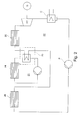
- FIG. 1 schematically shows the layout of a solar thermal power plant having a primary cycle 11 and a secondary cycle 12, which is also the water-steam cycle of the power plant.
- the primary and secondary cycles 11 and 12 are operatively connected with one another by a heat exchange system 13 comprising heat exchangers 13a and 13b.
- the feedwater is heated to almost saturation temperature in heat exchanger or preheater 13a, and the water is evaporated in evaporator 13b by means of the heat transferred from the thermal fluid circulating in the primary cycle 11.
- the thermal fluid in the primary cycle can be any known or suitable thermal fluid for heating by solar heat by circulation through a solar field 14.
- the solar field can, for example, have absorber tubes arranged in an array of parabolic troughs or other elements for collecting solar radiation.
- the steam generated in the heat exchanger or evaporator 13b is directed to a further solar field 15 arranged in the secondary cycle of the plant, which can be of same type as the solar field 14, or of another type, able to heat the steam circulating through piping to temperatures of up to 550°C at high pressures.
- the steam thus generated is directed to the steam turbine for expansion and to drive the generator G.
- the expanded steam is condensed in condenser C and recirculated via pump P to heat exchanger 13a for preheating, thus completing the water-steam cycle.
- the superheating of the steam is performed entirely by the solar field 15 in the secondary cycle, where the heat exchange system 13 performs preheating and evaporation only.
- the heat exchange system includes an additional heat exchanger to perform a first stage of the superheating, where the solar field 15 performs a second stage superheating.
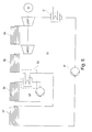
- FIG. 2 shows a solar thermal power plant that is an extension of the plant of figure 1 . Its basic structure is the same in that it comprises a secondary water steam cycle 22 with steam turbine ST, condenser C and heat exchange system 23.
- the primary cycle 21 provides the heat exchange system 23 with a thermal fluid heated in solar field 24.
- the feedwater circulating in the secondary cycle 22 is first preheated in a solar field 26 without phase change and then directed to the evaporator within the heat exchange system 23, where steam is generated using the heat provided by the thermal fluid in primary cycle 21.
- the steam is finally superheated in a solar field 25 and then directed to steam turbine ST. In both solar fields 24 and 25, a fluid is heated without a phase change.
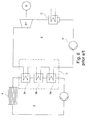
- Figure 3 comprises a secondary water steam cycle 32 with heat exchange system 33 comprising heat exchangers 33a-c, which generate a high temperature steam for a high-pressure steam turbine HPST.
- the thermal fluid heated in the solar field 34 of the primary cycle 31 provides the heat for the steam generator 33.
- the first heat exchanger 33a operates as preheater
- the second heat exchanger 33b operates as evaporator
- the third heat exchanger 33c as superheater of the steam.
- the secondary cycle comprises a further solar field 35 configured and arranged for the reheating of the steam exhausted by the high-pressure steam turbine HPST before it is directed to a low-pressure steam turbine LPST for further expansion.
- Figure 4 is an extension of the power plant of figure 3 in that it comprises in its secondary cycle 42, a first solar field 45 between the high-pressure steam turbine HPST and the low-pressure steam turbine LPST. In addition, it comprises a further solar field 46 arranged prior to the high-pressure steam turbine HPST to superheat steam for that turbine.
- the heat exchange system 43 comprises only two heat exchangers 43a and b operating as feedwater preheater and evaporator, respectively heated by the thermal fluid heated by the solar field 44 in the primary cycle 41.
- the solar field 46 in the secondary cycle is used for superheating the steam for the high-pressure steam turbine.
- FIG. 5 is a further extension of the plant of figure 4 .
- Its secondary cycle 52 comprises high- and low-pressure steam turbines HPST and LPST .
- Solar fields 55 and 56 arranged prior to the low-pressure and high-pressure steam turbines, respectively.
- a heat exchanger system 53 connecting primary and secondary cycles comprises one heat exchanger operating as evaporator, which generates steam by means of the thermal fluid heated by solar field 54 of the primary cycle 51.
- An additional solar field 57 is arranged in the secondary cycle for prehating the feedwater following the feedwater pump P. In this configuration, preheating, superheating as well as reheating of steam is performed by direct solar radiation of the water or steam, each without phase change. Heat exchange with phase change occurs only in the heat exchanger 53.
- the steam temperatures that can be achieved by means of the direct solar heating in the secondary cycle can reach up to 500°C.
- the proposed power plant may be operated in a sliding pressure mode or a fixed pressure operation.
- a fixed pressure operation mode may be preferred.
Priority Applications (2)
| Application Number | Priority Date | Filing Date | Title |
|---|---|---|---|
| EP11154221A EP2487338A1 (fr) | 2011-02-11 | 2011-02-11 | Centrale thermoélectrique solaire |
| PCT/EP2012/052112 WO2012107478A1 (fr) | 2011-02-11 | 2012-02-08 | Centrale thermique solaire |
Applications Claiming Priority (1)
| Application Number | Priority Date | Filing Date | Title |
|---|---|---|---|
| EP11154221A EP2487338A1 (fr) | 2011-02-11 | 2011-02-11 | Centrale thermoélectrique solaire |
Publications (1)
| Publication Number | Publication Date |
|---|---|
| EP2487338A1 true EP2487338A1 (fr) | 2012-08-15 |
Family
ID=44913455
Family Applications (1)
| Application Number | Title | Priority Date | Filing Date |
|---|---|---|---|
| EP11154221A Withdrawn EP2487338A1 (fr) | 2011-02-11 | 2011-02-11 | Centrale thermoélectrique solaire |
Country Status (2)
| Country | Link |
|---|---|
| EP (1) | EP2487338A1 (fr) |
| WO (1) | WO2012107478A1 (fr) |
Cited By (2)
| Publication number | Priority date | Publication date | Assignee | Title |
|---|---|---|---|---|
| CN103134213A (zh) * | 2013-03-12 | 2013-06-05 | 北京化工大学 | 以低水合氯化镁为储能工质对太阳能转化和储存的方法 |
| ES2482940R1 (es) * | 2011-08-30 | 2014-10-30 | Abengoa Solar Llc | Campo solar híbrido. |
Families Citing this family (5)
| Publication number | Priority date | Publication date | Assignee | Title |
|---|---|---|---|---|
| WO2012006288A2 (fr) | 2010-07-05 | 2012-01-12 | Glasspoint Solar, Inc. | Stockage d'énergie thermique souterrain d'une chaleur produite par concentration d'énergie solaire |
| US9200799B2 (en) | 2013-01-07 | 2015-12-01 | Glasspoint Solar, Inc. | Systems and methods for selectively producing steam from solar collectors and heaters for processes including enhanced oil recovery |
| EP3183512A4 (fr) | 2014-10-23 | 2018-09-05 | Glasspoint Solar, Inc. | Dispositif de stockage thermique pour la production solaire de vapeur d'eau et systèmes et procédés associés |
| AU2017216399A1 (en) | 2016-02-01 | 2018-08-09 | Glasspoint Solar, Inc. | Separators and mixers for delivering controlled-quality solar-generated steam over long distances for enhanced oil recovery, and associated systems and methods |
| EP3403032A4 (fr) * | 2016-02-22 | 2019-11-06 | Glasspoint Solar, Inc. | Dispositifs et circuits de stockage de chaleur pour la production solaire de vapeur, ainsi que systèmes et procédés associés |
Citations (7)
| Publication number | Priority date | Publication date | Assignee | Title |
|---|---|---|---|---|
| JPS60122865A (ja) * | 1983-12-07 | 1985-07-01 | Hitachi Ltd | 太陽熱発電装置 |
| DE10128562C1 (de) | 2001-06-13 | 2003-01-09 | Deutsch Zentr Luft & Raumfahrt | Solarthermisches Kraftwerk und Verfahren zur Umwandlung von thermischer Energie in mechanische/elektrische Energie in einem solarthermischen Kraftwerk |
| EP1519108A1 (fr) * | 2003-09-25 | 2005-03-30 | Deutsches Zentrum für Luft- und Raumfahrt e.V. | Procédé pour la génération de vapeur surchauffée, générateur de vapeur pour centrale et centrale d'énergie |
| WO2008113482A2 (fr) | 2007-03-20 | 2008-09-25 | Siemens Aktiengesellschaft | Procédé et dispositif de surchauffe intermédiaire par mise à feu lors de l'évaporation directe solaire dans une centrale thermique solaire |
| EP2000669A2 (fr) | 2007-06-07 | 2008-12-10 | Abengoa Solar New Technologies, S.A. | Usine de concentration solaire de production de vapeur surchauffée |
| WO2010054911A1 (fr) | 2008-11-12 | 2010-05-20 | Siemens Aktiengesellschaft | Procédé et dispositif pour le surchauffage intermédiaire dans une centrale solaire thermique avec vaporisation indirecte. |
| WO2011005923A2 (fr) * | 2009-07-08 | 2011-01-13 | Areva Solar, Inc. | Système de chauffage à énergie solaire pour fluide de travail |
-
2011
- 2011-02-11 EP EP11154221A patent/EP2487338A1/fr not_active Withdrawn
-
2012
- 2012-02-08 WO PCT/EP2012/052112 patent/WO2012107478A1/fr active Application Filing
Patent Citations (7)
| Publication number | Priority date | Publication date | Assignee | Title |
|---|---|---|---|---|
| JPS60122865A (ja) * | 1983-12-07 | 1985-07-01 | Hitachi Ltd | 太陽熱発電装置 |
| DE10128562C1 (de) | 2001-06-13 | 2003-01-09 | Deutsch Zentr Luft & Raumfahrt | Solarthermisches Kraftwerk und Verfahren zur Umwandlung von thermischer Energie in mechanische/elektrische Energie in einem solarthermischen Kraftwerk |
| EP1519108A1 (fr) * | 2003-09-25 | 2005-03-30 | Deutsches Zentrum für Luft- und Raumfahrt e.V. | Procédé pour la génération de vapeur surchauffée, générateur de vapeur pour centrale et centrale d'énergie |
| WO2008113482A2 (fr) | 2007-03-20 | 2008-09-25 | Siemens Aktiengesellschaft | Procédé et dispositif de surchauffe intermédiaire par mise à feu lors de l'évaporation directe solaire dans une centrale thermique solaire |
| EP2000669A2 (fr) | 2007-06-07 | 2008-12-10 | Abengoa Solar New Technologies, S.A. | Usine de concentration solaire de production de vapeur surchauffée |
| WO2010054911A1 (fr) | 2008-11-12 | 2010-05-20 | Siemens Aktiengesellschaft | Procédé et dispositif pour le surchauffage intermédiaire dans une centrale solaire thermique avec vaporisation indirecte. |
| WO2011005923A2 (fr) * | 2009-07-08 | 2011-01-13 | Areva Solar, Inc. | Système de chauffage à énergie solaire pour fluide de travail |
Cited By (3)
| Publication number | Priority date | Publication date | Assignee | Title |
|---|---|---|---|---|
| ES2482940R1 (es) * | 2011-08-30 | 2014-10-30 | Abengoa Solar Llc | Campo solar híbrido. |
| CN103134213A (zh) * | 2013-03-12 | 2013-06-05 | 北京化工大学 | 以低水合氯化镁为储能工质对太阳能转化和储存的方法 |
| CN103134213B (zh) * | 2013-03-12 | 2014-08-20 | 北京化工大学 | 以低水合氯化镁为储能工质对太阳能转化和储存的方法 |
Also Published As
| Publication number | Publication date |
|---|---|
| WO2012107478A1 (fr) | 2012-08-16 |
Similar Documents
| Publication | Publication Date | Title |
|---|---|---|
| EP2487338A1 (fr) | Centrale thermoélectrique solaire | |
| EP2622182B1 (fr) | Dispositif et processus de production de vapeur surchauffée à partir d'une centrale à énergie solaire à concentration | |
| ES2544467T3 (es) | Central térmica solar con evaporación indirecta y procedimiento para operar una tal central térmica solar | |
| US8365720B2 (en) | Solar concentration plant for the production of superheated steam | |
| AU2008228211B2 (en) | Method and device for intermediate superheating in solar direct evaporation in a solar-thermal power plant | |
| US20120274069A1 (en) | Dual fluid circuit system for generating a vaporous working fluid using solar energy | |
| US20130186089A1 (en) | Continuous flow steam generator having an integrated reheater | |
| US9080788B2 (en) | Solar power system and method of operation | |
| US20130047611A1 (en) | Solar power plant part of a solar thermal power plant and solar thermal power plant provided with solar collector surfaces for a heat transfer medium and working medium | |
| Hirsch et al. | A systematic comparison on power block efficiencies for CSP plants with direct steam generation | |
| US11060716B2 (en) | System and methods for integration of concentrated solar steam generators to Rankine cycle power plants | |
| US20130111902A1 (en) | Solar power system and method of operating a solar power system | |
| WO2013132132A2 (fr) | Procédé pour améliorer le rendement du cycle thermique dans les centrales nucléaires | |
| EP2861908B1 (fr) | Procédé de modification d'une centrale thermique solaire fonctionnant sur une technologie à base d'huile classique dans une centrale thermique solaire hybride et une telle installation d'énergie thermique solaire hybride | |
| WO2013087949A1 (fr) | Système hybride de génération d'électricité à partir d'énergie solaire et de biomasse | |
| WO2009045117A2 (fr) | Procédé d'utilisation de sources de chaleur et de milieu à des température faibles et moyennes et système d'utilisation de des sources et milieu à basse et moyenne température | |
| US20110162361A1 (en) | Method of superheating team | |
| CN105673367A (zh) | 超高温槽式太阳能光热发电系统 | |
| EP3093488A1 (fr) | Centrale d'énergie solaire thermique avec un appareil à accumulation de chaleur et procédé associé | |
| WO2013013682A1 (fr) | Agencement et procédé pour la compensation de la variation de charge sur une turbine à vapeur saturée | |
| ES2941540T3 (es) | Planta de generación de energía por incineración convencional de residuos y método | |
| KR20130134513A (ko) | 복수기 배출수의 여열 및 태양열을 이용한 해수 온도차 발전 시스템 | |
| KR20130128234A (ko) | 태양열 급수 가열 설비를 갖춘 발전 시스템 | |
| KR20210098151A (ko) | 복수기 방열 회수 시스템 | |
| WO2016156177A1 (fr) | Système et procédé de stockage d'énergie |
Legal Events
| Date | Code | Title | Description |
|---|---|---|---|
| PUAI | Public reference made under article 153(3) epc to a published international application that has entered the european phase |
Free format text: ORIGINAL CODE: 0009012 |
|
| AK | Designated contracting states |
Kind code of ref document: A1 Designated state(s): AL AT BE BG CH CY CZ DE DK EE ES FI FR GB GR HR HU IE IS IT LI LT LU LV MC MK MT NL NO PL PT RO RS SE SI SK SM TR |
|
| AX | Request for extension of the european patent |
Extension state: BA ME |
|
| 17P | Request for examination filed |
Effective date: 20130211 |
|
| STAA | Information on the status of an ep patent application or granted ep patent |
Free format text: STATUS: THE APPLICATION IS DEEMED TO BE WITHDRAWN |
|
| 18D | Application deemed to be withdrawn |
Effective date: 20140902 |