EP2487125A1 - Sheet width regulating device and image forming apparatus with sheet width regulating device - Google Patents
Sheet width regulating device and image forming apparatus with sheet width regulating device Download PDFInfo
- Publication number
- EP2487125A1 EP2487125A1 EP12000941A EP12000941A EP2487125A1 EP 2487125 A1 EP2487125 A1 EP 2487125A1 EP 12000941 A EP12000941 A EP 12000941A EP 12000941 A EP12000941 A EP 12000941A EP 2487125 A1 EP2487125 A1 EP 2487125A1
- Authority
- EP
- European Patent Office
- Prior art keywords
- sheet
- pinion
- regulating device
- guiding portion
- sheet width
- Prior art date
- Legal status (The legal status is an assumption and is not a legal conclusion. Google has not performed a legal analysis and makes no representation as to the accuracy of the status listed.)
- Granted
Links
- 230000001105 regulatory effect Effects 0.000 title claims abstract description 63
- 230000008878 coupling Effects 0.000 claims description 14
- 238000010168 coupling process Methods 0.000 claims description 14
- 238000005859 coupling reaction Methods 0.000 claims description 14
- 238000011144 upstream manufacturing Methods 0.000 claims description 9
- 230000002093 peripheral effect Effects 0.000 claims description 3
- 238000010276 construction Methods 0.000 description 17
- 210000000078 claw Anatomy 0.000 description 10
- 239000011295 pitch Substances 0.000 description 4
- 238000010586 diagram Methods 0.000 description 3
- 230000000694 effects Effects 0.000 description 3
- 238000000926 separation method Methods 0.000 description 3
- 230000008901 benefit Effects 0.000 description 2
- 230000015572 biosynthetic process Effects 0.000 description 2
- 239000011521 glass Substances 0.000 description 2
- 238000010438 heat treatment Methods 0.000 description 2
- 230000001360 synchronised effect Effects 0.000 description 2
- 238000010348 incorporation Methods 0.000 description 1
- 238000003780 insertion Methods 0.000 description 1
- 230000037431 insertion Effects 0.000 description 1
- 230000002452 interceptive effect Effects 0.000 description 1
- 230000001678 irradiating effect Effects 0.000 description 1
- 238000000034 method Methods 0.000 description 1
- 230000003287 optical effect Effects 0.000 description 1
Images



Classifications
-
- B—PERFORMING OPERATIONS; TRANSPORTING
- B65—CONVEYING; PACKING; STORING; HANDLING THIN OR FILAMENTARY MATERIAL
- B65H—HANDLING THIN OR FILAMENTARY MATERIAL, e.g. SHEETS, WEBS, CABLES
- B65H1/00—Supports or magazines for piles from which articles are to be separated
- B65H1/04—Supports or magazines for piles from which articles are to be separated adapted to support articles substantially horizontally, e.g. for separation from top of pile
-
- G—PHYSICS
- G03—PHOTOGRAPHY; CINEMATOGRAPHY; ANALOGOUS TECHNIQUES USING WAVES OTHER THAN OPTICAL WAVES; ELECTROGRAPHY; HOLOGRAPHY
- G03G—ELECTROGRAPHY; ELECTROPHOTOGRAPHY; MAGNETOGRAPHY
- G03G21/00—Arrangements not provided for by groups G03G13/00 - G03G19/00, e.g. cleaning, elimination of residual charge
-
- B—PERFORMING OPERATIONS; TRANSPORTING
- B65—CONVEYING; PACKING; STORING; HANDLING THIN OR FILAMENTARY MATERIAL
- B65H—HANDLING THIN OR FILAMENTARY MATERIAL, e.g. SHEETS, WEBS, CABLES
- B65H9/00—Registering, e.g. orientating, articles; Devices therefor
- B65H9/04—Fixed or adjustable stops or gauges
-
- G—PHYSICS
- G03—PHOTOGRAPHY; CINEMATOGRAPHY; ANALOGOUS TECHNIQUES USING WAVES OTHER THAN OPTICAL WAVES; ELECTROGRAPHY; HOLOGRAPHY
- G03G—ELECTROGRAPHY; ELECTROPHOTOGRAPHY; MAGNETOGRAPHY
- G03G15/00—Apparatus for electrographic processes using a charge pattern
-
- B—PERFORMING OPERATIONS; TRANSPORTING
- B65—CONVEYING; PACKING; STORING; HANDLING THIN OR FILAMENTARY MATERIAL
- B65H—HANDLING THIN OR FILAMENTARY MATERIAL, e.g. SHEETS, WEBS, CABLES
- B65H2403/00—Power transmission; Driving means
- B65H2403/40—Toothed gearings
- B65H2403/41—Rack-and-pinion, cogwheel in cog railway
-
- B—PERFORMING OPERATIONS; TRANSPORTING
- B65—CONVEYING; PACKING; STORING; HANDLING THIN OR FILAMENTARY MATERIAL
- B65H—HANDLING THIN OR FILAMENTARY MATERIAL, e.g. SHEETS, WEBS, CABLES
- B65H2403/00—Power transmission; Driving means
- B65H2403/40—Toothed gearings
- B65H2403/41—Rack-and-pinion, cogwheel in cog railway
- B65H2403/411—Double rack cooperating with one pinion, e.g. for performing symmetrical displacement relative to pinion
Definitions
- the present disclosure relates to a sheet width regulating device for aligning the orientation of various sheets such as a sheet width regulating device mainly used to align the orientation of a sheet or a document for image formation in an image forming apparatus such as a copier, a facsimile machine or a printer or a sheet width regulating device used to align the orientation of a document in a scanner apparatus which does not perform image formation.
- a sheet width regulating device for aligning the orientation of various sheets
- a sheet width regulating device mainly used to align the orientation of a sheet or a document for image formation in an image forming apparatus such as a copier, a facsimile machine or a printer or a sheet width regulating device used to align the orientation of a document in a scanner apparatus which does not perform image formation.
- the present disclosure also relates to an image forming apparatus with this sheet width regulating device.
- Such a conventional sheet cassette includes a pair of cursors for regulating the width of sheets stored in the sheet cassette and the sheets are positioned in a width direction by these cursors.
- the cursors need to be so aligned that a direction of sheets conforms to a feeding direction, they have a certain length along the sheet feeding direction.
- Such cursors normally have, for example, a length of about 20 cm to 30 cm along the sheet feeding direction.
- the cursors are so designed that a user can parallelly move them in a direction perpendicular to the sheet feeding direction while holding them by hands.
- the cursors have a certain length as described above, forces act on the cursors in a nonuniform manner depending on how the user moves the cursors, for example, when the user moves the cursors while holding ends of the cursors.
- the cursors may be inclined with respect to the sheet feeding direction.
- An object of the present disclosure is to provide a sheet width regulating device which reduces a possibility of inclining cursors and an image forming apparatus using this.
- One aspect of the present disclosure is directed to a sheet width regulating device, including a base plate, a regulating member, a first moving cursor, a first guiding portion, a second guiding portion, a first guidable portion, a second guidable portion, and a synchronizing member.
- a sheet having one end and the other end parallel to each other is to be placed on the base plate.
- the regulating member regulates one end of the sheet.
- the first moving cursor is a member for regulating the other end of the sheet, stands on the upper surface of the base plate and is movable in a way perpendicular to a direction along the other end of the sheet.
- the first guiding portion extends in the way on the upper surface of the base plate.
- the second guiding portion is spaced apart from and extends in parallel with the first guiding portion on the upper surface of the base plate.
- the first guidable portion is attached to the first moving cursor and guided by the first guiding portion.
- the second guidable portion is attached to the first moving cursor and guided by the second guiding portion.
- the synchronizing member synchronizes a movement of the first guidable portion guided by the first guiding portion and a movement of the second guidable portion guided by the second guiding portion.
- FIG. 1 is a schematic sectional view showing the entire construction of a copier according to one embodiment of the present disclosure.
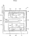
- FIGS. 2 to 12 are views showing essential constructions of a sheet cassette of the copier shown in FIG. 1 .
- arrows F and R in FIGS. 2 to 5 respectively indicate a device front side (F) and a device rear side (R) when the sheet cassette is mounted in the copier.
- the copier 100 of this embodiment is a center registration type copier and includes a sheet feeding unit 1 arranged in a lower part of an apparatus main body, a sheet conveying unit 2 arranged lateral to and above the sheet feeding unit 1, an image forming unit 3 arranged above the sheet conveying unit 2, a fixing unit 4 arranged downstream of the image forming unit 3 in a sheet conveying direction, an image reading unit 5 arranged above the image forming unit 3 and the fixing unit 4 and including optical members and the like, and an automatic document feeder (ADF) 7 openably and closably arranged on the image reading unit 5.
- ADF automatic document feeder
- the sheet feeding unit 1 is such that sheets P in a sheet stack stored in each sheet cassette 6 detachably mounted in the apparatus main body are fed to an exit side (right side in FIG. 1 ) of the sheet cassette 6 by the rotation of a cylindrical feed roller 11 and separated by a separating unit 12 provided above the exit side of each sheet cassette 6, whereby the sheets P can be reliably fed one by one to the sheet conveying unit 2 from the uppermost one.
- this copier 100 is so constructed that mounting and detaching directions of the sheet cassettes 6 into and from the apparatus main body are substantially perpendicular to a feeding direction of the sheets P from the sheet cassettes 6 to the apparatus main body.
- sheets P are examples of sheets.
- Sheets may be, for example, OHP films or the like.
- the sheet conveying unit 2 conveys the sheet P fed from the sheet feeding unit 1 toward the image forming unit 3 by pairs of conveyor rollers 21 and a pair of registration rollers 22 and further discharges the sheet P having an image formed thereon in the image forming unit 3 and the fixing unit 4 onto a discharge tray 24 by a pair of discharge rollers 23.
- the image forming unit 3 forms a predetermined toner image on a sheet P by an electrophotographic process.
- the image forming unit 3 includes a photoconductive drum 31 rotatably supported and having a photoconductive property and a charging unit 32, an exposure unit 33, a developing unit 34, a transfer unit 35, a cleaner 36 and a charge removing unit 37 arranged around the photoconductive drum 31.
- the charging unit 32 includes a charging wire to which a high voltage is to be applied.
- the charging unit 32 gives a predetermined potential to the surface of the photoconductive drum 31 by corona discharge from this charging wire.
- the exposure unit 33 selectively removes the potential of the surface of the photoconductive drum 31 and forms an electrostatic latent image on the surface of the photoconductive drum 31 by irradiating the photoconductive drum 31 with a laser beam output from a laser emitter via a polygon mirror and a reflecting mirror based on image data of a document read by the image reading unit 5 to be described later.
- the developing unit 34 develops the electrostatic latent image by toner to form a toner image on the surface of the photoconductive drum 31.
- the transfer unit 35 transfers the toner image on the surface of the photoconductive drum 31 to a sheet P.
- the transfer unit 35 includes a transfer roller arranged at a predetermined distance from the photoconductive drum 31.
- the cleaner 36 removes the toner remaining on the surface of the photoconductive drum 31 after image transfer.
- the charge removing unit 37 removes electric charges remaining on the surface of the photoconductive drum 31.
- the fixing unit 4 is arranged downstream of the image forming unit 3 in the sheet conveying direction and fixes a toner image to a sheet P by heating the sheet P having the toner image transferred thereto in the image forming unit 3 while sandwiching it between a heating roller 41 and a pressure roller 42.
- the image reading unit 5 irradiates a document placed on a contact glass 51 with light from an exposure lamp. Then, the image reading unit 5 introduces the reflected light of the irradiated light into a photoelectric converter composed of a CCD line sensor and the like via a reflecting mirror, thereby reading document image information. Note that the exposure lamp and the reflecting mirror form a scanning section of the image reading unit 5 and this scanning section moves a moving area 52 extending in a lateral direction of FIG. 1 at a predetermined speed, whereby the entire surface of the document placed on the contact glass 51 can be scanned to read an image on the entire document surface.
- the sheet cassette 6 includes a tray frame 61 and a sheet tray 62 mounted by being placed on the tray frame 61.
- the tray frame 61 is detachably mounted into the apparatus main body via a sliding mechanism 61a. If a user pulls a handle formed on a front cover 61b of the tray frame 61, the sliding mechanism 61a slides and the sheet cassette 6 can be pulled out forward. The user places sheets P on the sheet tray 62 of the sheet cassette 6 pulled out in this way.
- the sheet tray 62 includes a sheet storing portion 62a in the form of a recess in which the sheets P can be stacked and stored.
- a sheet width regulating unit 63 for regulating a width direction (direction perpendicular to the sheet conveying direction) of the sheets P, a length cursor 81 for regulating a length direction of the sheets P and a length cursor rail member 82 for supporting the length cursor 81 are arranged at the bottom of the sheet storing portion 62a.
- a predetermined sheet position corresponding to the size of the sheets P is regulated by the sheet width regulating unit 63 and the length cursor 81.
- the sheet width regulating unit 63 corresponds to an example of a sheet width regulating device.
- the length cursor 81 is slidable in the length direction of the sheets P on the length cursor rail member 82.
- the sheet position in the length direction (direction along the sheet feeding direction) of the sheets P is regulated by this length cursor 81 and the inner wall surface (right inner wall surface in FIG. 2 ) of the sheet tray 62 facing the length cursor 81.
- a substantially plate-like lifting member 65 which lifts the leading end of the sheet P in the feeding direction to bring it into contact with the feed roller 11 is provided above the sheet width regulating unit 63.
- the lifting member 65 is provided with a cutout formed to avoid the length cursor 81 and the length cursor rail member 82, and the length cursor 81 projects from the upper surface of the lifting member 65 through this cutout.
- the lifting member 65 is provided with two openings 65a. Width cursors 71a, 71b on a base plate 71 to be described later project from the upper surface of the lifting member 65 through these two openings 65a.
- the lifting member 65 is in the form of a flat plate which can cover the bottom surface of the sheet tray 62 without interfering with sliding movements of the respective cursors 71a, 71b and 81.
- the opposite front and rear ends of the back side (left side of FIG. 2 ) of the lifting member 65 in the sheet feeding direction are respectively rotatably supported by unillustrated pins mounted on front and rear side surface portions of the sheet tray 62, whereby an exit side (right side of FIG. 2 ) of the lifting member 65 in the sheet feeding direction can be raised and lowered relative to the bottom surface of the sheet tray 62.
- FIG. 3 is a perspective view showing the sheet width regulating unit 63 when viewed from above.
- FIG. 4 is a plan view showing the sheet width regulating unit 63 with the width cursor 71b removed.
- FIG. 5 is a bottom view of the sheet width regulating unit 63.
- the sheet width regulating unit 63 includes the pair of width cursors 71a, 71b for regulating the width direction of the sheets P, the base plate 73 slidably supporting this pair of width cursors 71a, 71b, racks 74a, 74b and a pinion 745 ( FIG. 5 ) as an example of a moving mechanism for moving the pair of width cursors 71a, 71b in tandem, and a stopper member 77 ( FIG. 3 ) for specifying the position of the width cursor 71b relative to the base plate 73 by being mounted on the front width cursor 71b.
- front width cursor 71b and the rear width cursor 71a are shown as examples of a first and a second moving cursors of the present disclosure, only one of the front and rear width cursors may be made movable and the other may be fixed without providing the above moving mechanism.
- the fixed width cursor corresponds to an example of a regulating member.
- Either one of the front and rear width cursors 71b, 71a may not be provided and the inner wall surface of the tray frame 61 may be used as a regulating member.
- the inner wall surface of the tray frame 61 facing a wall 711a of the rear width cursor 71a serves as the regulating member.
- the inner wall surface of the tray frame 61 facing a wall 711b of the front width cursor 71b serves as the regulating member.
- the stopper member 77 includes an unillustrated engaging claw which is engaged with, for example, an unillustrated engaging portion formed on the upper surface of the base plate 73. By engaging this engaging claw with the engaging portion of the base plate 73, the stopper member 77 fixes the position of the width cursor 71b to the base plate 73.
- the above pair of width cursors 71a, 71b are slidable in the width direction of the sheets P on the base plate 73 and move away from or toward each other by means of the racks 74a, 74b and the pinion 745, thereby widening or narrowing a distance (width) of the both width cursors 71a, 71b.
- the respective width cursors 71a, 71b include housings in the form of boxes having predetermined height, length and width. Further, plate-like horizontal portions 713a, 713b horizontally extending toward the other width cursors are connected to bottom parts of the width cursors 71a, 71b.
- the housing of the width cursor 71a includes walls 711a, 712a extending in the feeding direction of the sheets P.
- the width cursor 71b includes walls 711b, 712b extending in the feeding direction of the sheets P.
- the inner (facing sides of the width cursors 71a, 71b) surfaces of the walls 711a, 711b of the width cursors 71a, 71b come into contact with the sheets P to regulate the width of the sheets P.
- the horizontal portions 713a, 713b support parts of the sheets P near the lateral edges from below, whereby the sheets P can be stored in order.
- the pair of racks 74a, 74b are arranged on the lower surface of the base plate 73 with rack tooth portions 742a, 742b faced toward each other.
- the racks 74a, 74b are mounted to lower parts of the respective width cursors 71a, 71b by mounting portions 741a, 741b.
- the base plate 73 is formed with a pair of guide long holes 730 extending in the direction perpendicular to the feeding direction of the sheets P.
- the mounting portions 741a, 741b connect the width cursors 71a, 71b arranged on the upper surface of the base plate 73 and the racks 74a, 74b arranged on the lower surface of the base plate 73 through the pair of guide long holes 730.
- the pinion 745 engaged with the respective rack tooth portions 742a, 742b is provided between the pair of guide long holes 730.
- the racks 74a, 74b may be integrally formed to the respective width cursors 71a, 71b.
- the pinion 745 is rotatably supported about a boss 746 by inserting the boss 746 integrally formed to the base plate 73 into a boss insertion hole of the pinion 745.
- a drive force resulting from this movement is transmitted to a tooth portion of the pinion 745 via the rack tooth portion 742b of the rack 74b connected to the width cursor 71b, whereby the pinion 745 rotates about the boss 746. Further, a drive force resulting from this rotation is transmitted to the rack 74a via the rack tooth portion 742a engaged with the pinion 745, whereby the rack 74a moves by the same amount in a direction opposite to the moving direction of the rack 74b.
- the other width cursor (rear width cursor 71a) moves by the same amount in the opposite direction in tandem with the movement of the one width cursor.
- the other cursor when the user moves one cursor to bring it into contact with ends of sheets, the other cursor also moves in tandem to hold the sheets between the two cursors.
- the sheets can be easily positioned at a center position and user operability is improved.
- racks 921a, 921b (first rack) extending in the direction perpendicular to the feeding direction of the sheets P and racks 922a, 922b (second rack) extending in the direction perpendicular to the feeding direction, i.e. in parallel with the racks 921a, 921b at positions spaced apart from the racks 921a, 921b in the feeding direction of the sheets P are provided on the upper surface of the base plate 73.
- a gear tooth pitch of the racks 921a, 921b and that of the racks 922a, 922b are set to be equal.
- the racks 921a, 921b may be integrally formed to the base plate 73.
- the base plate 73 is formed with a guide long hole 93a (slit) extending in parallel with the rack 921a near the rack 921a and a guide long hole 93b (slit) extending in parallel with the rack 921b near the rack 921b.
- the moving cursor since a sliding direction of the first moving cursor is regulated by the slit, the moving cursor can be easily moved in one direction while a first guidable portion is guided by a first guiding portion.
- a wide enlarged portion 931a is formed at one end of the guide long hole 93a, and a wide enlarged portion 931b is formed at one end of the guide long hole 93b. Further, cutouts 923a, 923b are formed at positions respectively facing the enlarged portions 931a, 931b at downstream edge portions 924a, 924b of the base plate 73 in the sheet feeding direction.
- FIG. 6 is a perspective view of the width cursor 71a when viewed from below.
- FIG. 7 is a view showing the interior of the width cursor 71a with the wall 711a removed. Note that the width cursor 71b is not described since being constructed substantially similarly to the width cursor 71a except in not including a locking portion 720 to be described later, but including the stopper member 77.
- a coupling shaft 76 is supported between the walls 711a, 712a in parallel with the walls 711a, 712a and the upper surface of the base plate 73 in a lower part of the width cursor 71a.
- a pinion 761 (first pinion) is coaxially and fixedly mounted on the coupling shaft 76 near one end, and a pinion 762 (second pinion) is coaxially and fixedly mounted on the coupling shaft 76 near the other end.
- the pinions 761, 762 are coupled by the coupling shaft 76 and coaxially rotated in tandem. Diameters and tooth numbers (pitches) of the pinions 761, 762 are equal to each other.
- the locking portion 720 for locking the rotation of the pinion 761 about the coupling shaft 76 is arranged above the pinion 761.
- an engaging portion 751 projecting downward near the pinion 761 and an engaging portion 752 (second engaging portion) projecting downward at a downstream end of the width cursor 71a in the sheet feeding direction are provided at the bottom of the width cursor 71a.
- the projections 751x, 752x are positioned in the enlarged portion 931a and the cutout 923a of the base plate 73 and the width cursor 71a is mounted on the base plate 73, the lower surface of the width cursor 71a is held in contact with the upper surface of the base plate 73, the pinions 761, 762 are engaged with the racks 921a, 922a and further the projections 751x, 752x project on the lower surface of the base plate 73.
- the projection 751x enters an end of the guide long hole 93a and is engaged to embrace an edge portion 932a which is an edge portion of the base plate 73. Further, the projection 752x is engaged to embrace an edge portion 924a of the base plate 73.
- the diameters and tooth pitches of the pinions 761, 762 are set to be equal and the gear tooth pitch of the rack 921a and that of the rack 922a are set to be equal. Accordingly, if the rotation amount of the pinion 761 and that of the pinion 762 are equal, a sliding amount of the width cursor 71a at the position of the pinion 761 and that of the width cursor 71a at the position of the pinion 762 are equal. Then, the width cursor 71a parallelly moves, wherefore there is no possibility of inclining the cursor with respect to the sheet feeding direction.
- the first moving cursor is slidably engaged with the base plate near the first guiding portion and a second guiding portion.
- separation of the first and second guiding portions and the first and second guidable portions is prevented.
- the first and second guidable portions are reliably guided by the first and second guiding portions, wherefore reliability of being able to prevent the inclination of the cursor is improved.
- the projections act to prevent the first moving cursor from being separated from the base plate according to this construction, separation of the first and second guiding portions and the first and second guidable portions is prevented. As a result, an effect of preventing separation of the first and second guiding portions and the first and second guidable portions is increased.
- the pinions 761, 762 only have to be supported on the coupling shaft 76 while being spaced apart from each other, and the coupled positions of the pinions 761, 762 to the coupling shaft 76 are not limited. However, it is preferable in terms of improving the effect of preventing the inclination of the cursor to arrange the pinions 761, 762 such that a center position A of the width cursor 71a in the feeding direction is located between the pinions 761, 762.
- the first and the second guidable portions are arranged at positions distant from the center of the first moving cursor toward one and the other ends and the movement amounts of the first moving cursor on the base plate are equal at these positions.
- the racks 921a, 921b are shown as an example of the first guiding portion
- the racks 922a, 922b are shown as an example of the second guiding portion
- the pinion 761 first pinion
- the pinion 762 second pinion
- the coupling shaft 76 is shown as an example of a synchronizing member
- the first and second guiding portions are not limited to the racks
- the first and second guidable portions are not limited to the pinions
- the synchronizing member is not limited to the coupling shaft.
- a plurality of small projections may be formed in a row at regular intervals in the direction perpendicular to the feeding direction of the sheets P on the upper surface of the base plate 73 as the first guiding portion, projections arranged in a row parallel to the first guiding portion are formed on the upper surface of the base plate 73 as the second guiding portion, and arrangement intervals of the projection rows may be set to be equal between the first and second guiding portions.
- the moving cursor may include a first claw member to be fitted into recesses between the projections of the first guiding portion as the first guidable portion and a second claw member to be fitted into recesses between the projections of the second guiding portion as the second guidable portion.
- the first and second claw members are held, for example, by elastic holding members.
- a coupling bar for synchronizing movements of the first and second claw members to be fitted into the recesses and move over the projections may be provided as the synchronizing member. This causes the first and second claw members to move over the projections in synchronization when the moving cursor is slid in the direction perpendicular to the feeding direction of the sheets P. As a result, the movement amount of the moving cursor at the position where the first claw member is attached and that of the moving cursor at the position where the second claw member is attached become equal, wherefore a possibility of inclining the moving cursor is reduced in sliding the moving cursor.
- the first and second guidable portions move while being guided by the first and second guiding portions.
- the first and second guidable portions move in parallel. Since the first and second guidable portions are attached to the first moving cursor while being spaced apart, the first moving cursor parallelly moves when the first and second guidable portions move in parallel on the base plate. As a result, the possibility of inclining the cursor is reduced.
- FIGS. 8 , 9 and 10 are diagrams showing an exemplary construction of the locking portion 720.
- the locking portion 720 includes a switching knob 72 (switching member) and a locking member 78.
- the switching knob 72 is a box-like member substantially in the form of a rectangular parallelepiped with an open lower surface. Bosses 721, 721 projecting toward the walls 711a, 712a are formed at the opposite sides of a bottom part of the switching knob 72 substantially near the center.
- the bosses 721 are fitted in unillustrated recesses formed in the walls 711a, 712a. In this way, the switching knob 72 is rotatably supported by the bosses 721 and rotatable about the bosses 721.
- Boss holes 723, 723 are formed in the opposite side wall surfaces of the switching knob 72 at positions spaced apart from and upstream of the bosses 721, 721 in the sheet feeding direction.
- a projection 722 projecting toward the wall 712a is provided on a wall surface of the switching knob 72 facing the wall 712a (see FIG. 7 ).
- the wall 712a is formed with holes 74, 75 spaced apart in a vertical direction.
- the switching knob 72 rotates to raise a downstream end C of the upper surface of the switching knob 72 in the sheet feeding direction and the projection 722 is fitted into the upper hole 74 to lock the switching knob 72.
- a state where the projection 722 is fitted in the upper hole 74 and the switching knob 72 is locked is called a locking posture below.
- FIG. 9 is an outer shape diagram showing an exemplary shape of the locking member 78.
- the locking member 78 includes a plate-like member 781 long substantially in the vertical direction. Cylindrical bosses 785, 785 projecting toward the opposite sides in a direction (lateral direction in FIG. 9 ) perpendicular to a thickness direction are provided at the upper end of the plate-like member 781. The bosses 785, 785 are fitted into the boss holes 723, 723. In this way, the locking member 78 is rotatable about the bosses 785, 785.
- a tooth portion 782 to be engaged with gear teeth on the peripheral surface of the pinion 761 from above are formed at the lower end of the plate-like member 781.
- Guide members 783, 783 projecting toward the upstream side in the sheet feeding direction are formed above the tooth portion 782.
- Plate-like members 715, 716 formed to sandwich the locking member 78 from the opposite sides and extending in the vertical direction are mounted between the walls 711a, 712a of the width cursor 71a ( FIG. 7 ).
- the guide members 783, 783 position the tooth portion 782 on the peripheral surface of the pinion 761 by coming into contact with the plate-like member 715.
- guide members 784, 784 projecting toward the opposite sides in the direction (lateral direction in FIG. 9 ) perpendicular to the thickness direction are formed at lateral end portions of the plate-like member 781 near a substantially longitudinal center.
- the guide members 784, 784 are held in contact with the inner wall surfaces of the walls 711a, 712a of the width cursor 71a.
- Unillustrated guide grooves extending upward from the pinion 761 are formed in the inner wall surfaces of the walls 711a, 712a, and the guid members 784, 784 are slidably fitted into these guide grooves.
- FIG. 10 is a diagram of the locking portion 720 when viewed in a direction of an arrow D, i.e. from the left side in FIG. 8 and shows a state where the tooth portion 782 is engaged in the case where the switching knob 72 is in the locking posture. Note that although gear teeth are formed on the entire periphery of the pinion 761, some teeth are not shown in FIG. 10 .
- the copier 100 shown in FIG. 1 is so constructed that the feeding direction of a sheet P from the sheet cassette 6 is substantially perpendicular to the mounting and detaching directions of the sheet cassette 6 into and from the apparatus main body, a large impact (impact in the direction of the arrow R) acts on the rear width cursor 71a located at the back side of the sheet tray 62 in an inserting direction due to an inertial force of sheets P stacked and stored in the sheet cassette 6 in mounting the sheet cassette 6 into the apparatus main body.
- the width cursor 71a may be moved by the inertial force of the sheets P.
- the width cursor 71a includes the locking portion 720, a possibility of moving the width cursor 71a can be prevented by the user operating the switching knob 72 and setting it to the locking posture even if the inertial force of the sheets P acts on the width cursor 71a.
- a movement of at least one of the first and second guidable portions is locked by the locking portion. Since movements of the first and second guidable portions are synchronized by the synchronizing member, the movements of the first and second guidable portions are both stopped if the movement of at least one of the first and second guidable portions is locked. In this way, a possibility of sliding the first moving cursor relative to the base plate can be reduced.
- the user needs to operate the stopper member 77 by inserting his hand to the back side beyond the width cursor 71a. Thus, this operation is very difficult.
- the switching knob 72 is provided at the upper part of the width cursor 71a, operability is improved.
- the switching knob 72 can be easily provided at the upper part of the width cursor 71a.
- the locking portion 720 suppresses the movement of the width cursor 71a utilizing the pinion 761 and the rack 921a provided to prevent the inclination of the width cursor 71a with respect to the sheet feeding direction, it is not necessary to separately provide the stopper member 77 and the engaging portion of the base plate 73 only to suppress the movement of the width cursor 71a.
- a locking member 78a shown in FIGS. 11 and 12 may be used instead of the locking member 78.
- the locking member 78a differs from the locking portion 78 in including a tooth portion 782a instead of the tooth portion 782.
- the locking member 78a includes the tooth portion 782a to be engaged with the teeth of the pinion 761 located downstream of a top T of the pinion 761 in a rotation direction Y of the pinion 761 when the width cursor 71a is moved in the direction of the arrow R (direction to move the width cursors 71a, 71b away from each other) and does not include teeth to be engaged with the teeth of the pinion 761 located upstream of the top T of the pinion 761.
- a gravity-defying force acts to push up the tooth portion 782 from the teeth of the pinion 761.
- an engaging force between the tooth portion 782 and the pinion 761 is weakened and the tooth portion 782 and the pinion 761 slip without being able to resist the inertial force of the sheets P and the width cursor 71a becomes more easily movable.
- width cursor 71b may also include the locking portion 720.
- width cursors 71a, 71b are both moving cursors.
- either one of the width cursors 71a, 71b may be fixed to the base plate 73.
- the sheet width regulating unit 63 may be provided, for example, in the automatic document feeder 7 and used to regulate the width of a document. Further, the sheet width regulating unit 63 may also be used in an unillustrated manual feed tray.
- the present disclosure is not limited to this and the above sheet width regulating device may be applied to a sheet feeder of a copier constructed such that mounting and detaching direction of a sheet cassette and a feeding direction into an apparatus main body are same, e.g. the sheet cassette is pulled out from the right side in FIG. 1 .
Landscapes
- Physics & Mathematics (AREA)
- General Physics & Mathematics (AREA)
- Engineering & Computer Science (AREA)
- Mechanical Engineering (AREA)
- Sheets, Magazines, And Separation Thereof (AREA)
Abstract
Description
- This application is based on and claims the benefit of priority from Japanese patent application No.
2011-028430 - The present disclosure relates to a sheet width regulating device for aligning the orientation of various sheets such as a sheet width regulating device mainly used to align the orientation of a sheet or a document for image formation in an image forming apparatus such as a copier, a facsimile machine or a printer or a sheet width regulating device used to align the orientation of a document in a scanner apparatus which does not perform image formation. The present disclosure also relates to an image forming apparatus with this sheet width regulating device.
- Conventionally, there has been known an image forming apparatus with a sheet cassette of a center registration type which is detachably mounted into an apparatus main body and stores sheets to be fed to the apparatus main body. Such a conventional sheet cassette includes a pair of cursors for regulating the width of sheets stored in the sheet cassette and the sheets are positioned in a width direction by these cursors.
- Since the cursors need to be so aligned that a direction of sheets conforms to a feeding direction, they have a certain length along the sheet feeding direction. Such cursors normally have, for example, a length of about 20 cm to 30 cm along the sheet feeding direction. The cursors are so designed that a user can parallelly move them in a direction perpendicular to the sheet feeding direction while holding them by hands.
- However, since the cursors have a certain length as described above, forces act on the cursors in a nonuniform manner depending on how the user moves the cursors, for example, when the user moves the cursors while holding ends of the cursors. Thus, the cursors may be inclined with respect to the sheet feeding direction.
- An object of the present disclosure is to provide a sheet width regulating device which reduces a possibility of inclining cursors and an image forming apparatus using this.
- One aspect of the present disclosure is directed to a sheet width regulating device, including a base plate, a regulating member, a first moving cursor, a first guiding portion, a second guiding portion, a first guidable portion, a second guidable portion, and a synchronizing member. A sheet having one end and the other end parallel to each other is to be placed on the base plate. The regulating member regulates one end of the sheet. The first moving cursor is a member for regulating the other end of the sheet, stands on the upper surface of the base plate and is movable in a way perpendicular to a direction along the other end of the sheet. The first guiding portion extends in the way on the upper surface of the base plate. The second guiding portion is spaced apart from and extends in parallel with the first guiding portion on the upper surface of the base plate. The first guidable portion is attached to the first moving cursor and guided by the first guiding portion. The second guidable portion is attached to the first moving cursor and guided by the second guiding portion. The synchronizing member synchronizes a movement of the first guidable portion guided by the first guiding portion and a movement of the second guidable portion guided by the second guiding portion.
- These and other objects, features and advantages of the present invention will become more apparent upon reading the following detailed description along with the accompanying drawings.
-
-
FIG. 1 is a schematic sectional view of a copier showing the entire construction of the copier according to one embodiment of the present disclosure, -
FIG. 2 is a plan view of a sheet cassette provided in the copier ofFIG. 1 , -
FIG. 3 is a perspective view showing a sheet width regulating unit provided in the sheet cassette ofFIG. 2 when viewed from above, -
FIG. 4 is a plan view showing the sheet width regulating unit ofFIG. 3 with one width cursor removed, -
FIG. 5 is a bottom view of the sheet width regulating unit ofFIG. 3 , -
FIG. 6 is a perspective view of the width cursor when viewed from below, -
FIG. 7 is a perspective view showing the interior of the width cursor with one wall removed, -
FIG. 8 is a perspective view showing an exemplary construction of a locking portion provided in the width cursor, -
FIG. 9 is a front view showing a locking member, -
FIG. 10 is a front view showing a locked state of the locking member and a pinion, -
FIG. 11 is a front view showing another locking member, and -
FIG. 12 is a front view showing a locked state of the other locking member and the pinion. - Hereinafter, an embodiment according to the present disclosure is described based on the drawings. Note that, in respective figures, members denoted by the same reference numerals are indicated to be the same members and not repeatedly described.
FIG. 1 is a schematic sectional view showing the entire construction of a copier according to one embodiment of the present disclosure.FIGS. 2 to 12 are views showing essential constructions of a sheet cassette of the copier shown inFIG. 1 . Note that arrows F and R inFIGS. 2 to 5 respectively indicate a device front side (F) and a device rear side (R) when the sheet cassette is mounted in the copier. First, with reference toFIG. 1 , the entire construction of thecopier 100 according to one embodiment of the present disclosure is described. - The
copier 100 of this embodiment is a center registration type copier and includes a sheet feeding unit 1 arranged in a lower part of an apparatus main body, asheet conveying unit 2 arranged lateral to and above the sheet feeding unit 1, animage forming unit 3 arranged above thesheet conveying unit 2, afixing unit 4 arranged downstream of theimage forming unit 3 in a sheet conveying direction, animage reading unit 5 arranged above theimage forming unit 3 and thefixing unit 4 and including optical members and the like, and an automatic document feeder (ADF) 7 openably and closably arranged on theimage reading unit 5. - The sheet feeding unit 1 is such that sheets P in a sheet stack stored in each
sheet cassette 6 detachably mounted in the apparatus main body are fed to an exit side (right side inFIG. 1 ) of thesheet cassette 6 by the rotation of acylindrical feed roller 11 and separated by a separatingunit 12 provided above the exit side of eachsheet cassette 6, whereby the sheets P can be reliably fed one by one to thesheet conveying unit 2 from the uppermost one. Note that thiscopier 100 is so constructed that mounting and detaching directions of thesheet cassettes 6 into and from the apparatus main body are substantially perpendicular to a feeding direction of the sheets P from thesheet cassettes 6 to the apparatus main body. - Note that the sheets P are examples of sheets. Sheets may be, for example, OHP films or the like.
- The
sheet conveying unit 2 conveys the sheet P fed from the sheet feeding unit 1 toward theimage forming unit 3 by pairs ofconveyor rollers 21 and a pair ofregistration rollers 22 and further discharges the sheet P having an image formed thereon in theimage forming unit 3 and thefixing unit 4 onto adischarge tray 24 by a pair ofdischarge rollers 23. - The
image forming unit 3 forms a predetermined toner image on a sheet P by an electrophotographic process. Theimage forming unit 3 includes aphotoconductive drum 31 rotatably supported and having a photoconductive property and acharging unit 32, anexposure unit 33, a developingunit 34, atransfer unit 35, acleaner 36 and acharge removing unit 37 arranged around thephotoconductive drum 31. - The
charging unit 32 includes a charging wire to which a high voltage is to be applied. Thecharging unit 32 gives a predetermined potential to the surface of thephotoconductive drum 31 by corona discharge from this charging wire. Theexposure unit 33 selectively removes the potential of the surface of thephotoconductive drum 31 and forms an electrostatic latent image on the surface of thephotoconductive drum 31 by irradiating thephotoconductive drum 31 with a laser beam output from a laser emitter via a polygon mirror and a reflecting mirror based on image data of a document read by theimage reading unit 5 to be described later. - The developing
unit 34 develops the electrostatic latent image by toner to form a toner image on the surface of thephotoconductive drum 31. Thetransfer unit 35 transfers the toner image on the surface of thephotoconductive drum 31 to a sheet P. In this copier, thetransfer unit 35 includes a transfer roller arranged at a predetermined distance from thephotoconductive drum 31. Thecleaner 36 removes the toner remaining on the surface of thephotoconductive drum 31 after image transfer. Thecharge removing unit 37 removes electric charges remaining on the surface of thephotoconductive drum 31. - The
fixing unit 4 is arranged downstream of theimage forming unit 3 in the sheet conveying direction and fixes a toner image to a sheet P by heating the sheet P having the toner image transferred thereto in theimage forming unit 3 while sandwiching it between aheating roller 41 and apressure roller 42. - The
image reading unit 5 irradiates a document placed on acontact glass 51 with light from an exposure lamp. Then, theimage reading unit 5 introduces the reflected light of the irradiated light into a photoelectric converter composed of a CCD line sensor and the like via a reflecting mirror, thereby reading document image information. Note that the exposure lamp and the reflecting mirror form a scanning section of theimage reading unit 5 and this scanning section moves a movingarea 52 extending in a lateral direction ofFIG. 1 at a predetermined speed, whereby the entire surface of the document placed on thecontact glass 51 can be scanned to read an image on the entire document surface. - Next, the construction of the
above sheet cassette 6 is described in detail with reference toFIGS. 2 to 12 . - The
sheet cassette 6 includes atray frame 61 and asheet tray 62 mounted by being placed on thetray frame 61. Thetray frame 61 is detachably mounted into the apparatus main body via a slidingmechanism 61a. If a user pulls a handle formed on afront cover 61b of thetray frame 61, the slidingmechanism 61a slides and thesheet cassette 6 can be pulled out forward. The user places sheets P on thesheet tray 62 of thesheet cassette 6 pulled out in this way. - As shown in
FIG. 2 , thesheet tray 62 includes asheet storing portion 62a in the form of a recess in which the sheets P can be stacked and stored. A sheetwidth regulating unit 63 for regulating a width direction (direction perpendicular to the sheet conveying direction) of the sheets P, alength cursor 81 for regulating a length direction of the sheets P and a lengthcursor rail member 82 for supporting thelength cursor 81 are arranged at the bottom of thesheet storing portion 62a. A predetermined sheet position corresponding to the size of the sheets P is regulated by the sheetwidth regulating unit 63 and thelength cursor 81. The sheetwidth regulating unit 63 corresponds to an example of a sheet width regulating device. - The
length cursor 81 is slidable in the length direction of the sheets P on the lengthcursor rail member 82. The sheet position in the length direction (direction along the sheet feeding direction) of the sheets P is regulated by thislength cursor 81 and the inner wall surface (right inner wall surface inFIG. 2 ) of thesheet tray 62 facing thelength cursor 81. - A substantially plate-
like lifting member 65 which lifts the leading end of the sheet P in the feeding direction to bring it into contact with thefeed roller 11 is provided above the sheetwidth regulating unit 63. The liftingmember 65 is provided with a cutout formed to avoid thelength cursor 81 and the lengthcursor rail member 82, and thelength cursor 81 projects from the upper surface of the liftingmember 65 through this cutout. - Further, the lifting
member 65 is provided with twoopenings 65a.Width cursors member 65 through these twoopenings 65a. - The lifting
member 65 is in the form of a flat plate which can cover the bottom surface of thesheet tray 62 without interfering with sliding movements of therespective cursors FIG. 2 ) of the liftingmember 65 in the sheet feeding direction are respectively rotatably supported by unillustrated pins mounted on front and rear side surface portions of thesheet tray 62, whereby an exit side (right side ofFIG. 2 ) of the liftingmember 65 in the sheet feeding direction can be raised and lowered relative to the bottom surface of thesheet tray 62. -
FIG. 3 is a perspective view showing the sheetwidth regulating unit 63 when viewed from above.FIG. 4 is a plan view showing the sheetwidth regulating unit 63 with thewidth cursor 71b removed.FIG. 5 is a bottom view of the sheetwidth regulating unit 63. - The sheet
width regulating unit 63 includes the pair ofwidth cursors base plate 73 slidably supporting this pair ofwidth cursors racks FIG. 5 ) as an example of a moving mechanism for moving the pair ofwidth cursors FIG. 3 ) for specifying the position of thewidth cursor 71b relative to thebase plate 73 by being mounted on thefront width cursor 71b. Note that although thefront width cursor 71b and therear width cursor 71a are shown as examples of a first and a second moving cursors of the present disclosure, only one of the front and rear width cursors may be made movable and the other may be fixed without providing the above moving mechanism. In this case, the fixed width cursor corresponds to an example of a regulating member. - Either one of the front and
rear width cursors tray frame 61 may be used as a regulating member. For example, in the case of not providing thefront width cursor 71b, the inner wall surface of thetray frame 61 facing awall 711a of therear width cursor 71a serves as the regulating member. For example, in the case of not providing therear width cursor 71a, the inner wall surface of thetray frame 61 facing awall 711b of thefront width cursor 71b serves as the regulating member. - The
stopper member 77 includes an unillustrated engaging claw which is engaged with, for example, an unillustrated engaging portion formed on the upper surface of thebase plate 73. By engaging this engaging claw with the engaging portion of thebase plate 73, thestopper member 77 fixes the position of thewidth cursor 71b to thebase plate 73. - The above pair of
width cursors base plate 73 and move away from or toward each other by means of theracks pinion 745, thereby widening or narrowing a distance (width) of the bothwidth cursors - Further, the
respective width cursors horizontal portions width cursors - The housing of the
width cursor 71a includeswalls width cursor 71b includeswalls width cursors walls width cursors - The
horizontal portions - As shown in
FIG. 5 , the pair ofracks base plate 73 withrack tooth portions racks respective width cursors portions base plate 73 is formed with a pair of guidelong holes 730 extending in the direction perpendicular to the feeding direction of the sheets P. The mountingportions width cursors base plate 73 and theracks base plate 73 through the pair of guidelong holes 730. Further, thepinion 745 engaged with the respectiverack tooth portions long holes 730. Note that theracks respective width cursors - The
pinion 745 is rotatably supported about aboss 746 by inserting theboss 746 integrally formed to thebase plate 73 into a boss insertion hole of thepinion 745. - According to a linking structure of the sheet
width regulating unit 63, when the user moves one width cursor (e.g.front width cursor 71b), a drive force resulting from this movement is transmitted to a tooth portion of thepinion 745 via therack tooth portion 742b of therack 74b connected to thewidth cursor 71b, whereby thepinion 745 rotates about theboss 746. Further, a drive force resulting from this rotation is transmitted to therack 74a via therack tooth portion 742a engaged with thepinion 745, whereby therack 74a moves by the same amount in a direction opposite to the moving direction of therack 74b. As a result, by operating only one width cursor (front width cursor 71b), the other width cursor (rear width cursor 71a) moves by the same amount in the opposite direction in tandem with the movement of the one width cursor. - According to this construction, when the user moves one cursor to bring it into contact with ends of sheets, the other cursor also moves in tandem to hold the sheets between the two cursors. Thus, the sheets can be easily positioned at a center position and user operability is improved.
- As shown in
FIGS. 3 and4 ,racks racks racks racks base plate 73. - A gear tooth pitch of the
racks racks racks base plate 73. - Further, the
base plate 73 is formed with a guidelong hole 93a (slit) extending in parallel with therack 921a near therack 921a and a guidelong hole 93b (slit) extending in parallel with therack 921b near therack 921b. - According to this construction, since a sliding direction of the first moving cursor is regulated by the slit, the moving cursor can be easily moved in one direction while a first guidable portion is guided by a first guiding portion.
- A wide
enlarged portion 931a is formed at one end of the guidelong hole 93a, and a wideenlarged portion 931b is formed at one end of the guidelong hole 93b. Further,cutouts enlarged portions downstream edge portions base plate 73 in the sheet feeding direction. -
FIG. 6 is a perspective view of thewidth cursor 71a when viewed from below.FIG. 7 is a view showing the interior of thewidth cursor 71a with thewall 711a removed. Note that thewidth cursor 71b is not described since being constructed substantially similarly to thewidth cursor 71a except in not including a lockingportion 720 to be described later, but including thestopper member 77. - A
coupling shaft 76 is supported between thewalls walls base plate 73 in a lower part of thewidth cursor 71a. A pinion 761 (first pinion) is coaxially and fixedly mounted on thecoupling shaft 76 near one end, and a pinion 762 (second pinion) is coaxially and fixedly mounted on thecoupling shaft 76 near the other end. In this way, thepinions coupling shaft 76 and coaxially rotated in tandem. Diameters and tooth numbers (pitches) of thepinions - The locking
portion 720 for locking the rotation of thepinion 761 about thecoupling shaft 76 is arranged above thepinion 761. - Further, an engaging portion 751 (first engaging portion) projecting downward near the
pinion 761 and an engaging portion 752 (second engaging portion) projecting downward at a downstream end of thewidth cursor 71a in the sheet feeding direction are provided at the bottom of thewidth cursor 71a.Projections portions - When the
projections enlarged portion 931a and thecutout 923a of thebase plate 73 and thewidth cursor 71a is mounted on thebase plate 73, the lower surface of thewidth cursor 71a is held in contact with the upper surface of thebase plate 73, thepinions racks projections base plate 73. - When the
width cursor 71a is slid in a direction of an arrow R in this state, theprojection 751x enters an end of the guidelong hole 93a and is engaged to embrace anedge portion 932a which is an edge portion of thebase plate 73. Further, theprojection 752x is engaged to embrace anedge portion 924a of thebase plate 73. - Further, when the
width cursor 71a is slid, thepinions racks pinions racks pinions coupling shaft 76, a rotation amount of thepinion 761 and that of thepinion 762 are naturally equal. - Further, the diameters and tooth pitches of the
pinions rack 921a and that of therack 922a are set to be equal. Accordingly, if the rotation amount of thepinion 761 and that of thepinion 762 are equal, a sliding amount of thewidth cursor 71a at the position of thepinion 761 and that of thewidth cursor 71a at the position of thepinion 762 are equal. Then, thewidth cursor 71a parallelly moves, wherefore there is no possibility of inclining the cursor with respect to the sheet feeding direction. - According to this construction, when the user slides the first moving cursor in one direction, the first and second racks engaged with the first and second pinions relatively move, wherefore the first and second pinions rotate. At this time, since the first and second pinions are rotated coaxially and in tandem by the coupling shaft, the rotation amounts of the first and second pinions are equal. Thus, movement amounts of the first and second pinions on the base plate on which the first and second racks are provided become equal. Since the first and second pinions are attached to the moving cursor while being spaced apart, the moving cursor parallelly moves if the movement amounts of the first and second pinions on the base plate are equal. As a result, a possibility of inclining the cursor can be reduced.
- At this time, since the
projection 751x is engaged to embrace theedge portion 932a and theprojection 752x is engaged to embrace theedge portion 924a, it is prevented that thewidth cursor 71a is lifted from thebase plate 73 during a sliding movement. As a result, theracks pinions racks pinions - According to this construction, the first moving cursor is slidably engaged with the base plate near the first guiding portion and a second guiding portion. As a result, separation of the first and second guiding portions and the first and second guidable portions is prevented. As a result, the first and second guidable portions are reliably guided by the first and second guiding portions, wherefore reliability of being able to prevent the inclination of the cursor is improved.
- Further, since the projections act to prevent the first moving cursor from being separated from the base plate according to this construction, separation of the first and second guiding portions and the first and second guidable portions is prevented. As a result, an effect of preventing separation of the first and second guiding portions and the first and second guidable portions is increased.
- Note that the
pinions coupling shaft 76 while being spaced apart from each other, and the coupled positions of thepinions coupling shaft 76 are not limited. However, it is preferable in terms of improving the effect of preventing the inclination of the cursor to arrange thepinions width cursor 71a in the feeding direction is located between thepinions - According to this construction, the first and the second guidable portions are arranged at positions distant from the center of the first moving cursor toward one and the other ends and the movement amounts of the first moving cursor on the base plate are equal at these positions. Thus, a force trying to parallelly move the first moving cursor is produced in a well-balanced manner, with the result that an effect of reducing the inclination of the cursor is increased.
- Further, although the
racks racks coupling shaft 76 is shown as an example of a synchronizing member, the first and second guiding portions are not limited to the racks, the first and second guidable portions are not limited to the pinions and the synchronizing member is not limited to the coupling shaft. - For example, a plurality of small projections may be formed in a row at regular intervals in the direction perpendicular to the feeding direction of the sheets P on the upper surface of the
base plate 73 as the first guiding portion, projections arranged in a row parallel to the first guiding portion are formed on the upper surface of thebase plate 73 as the second guiding portion, and arrangement intervals of the projection rows may be set to be equal between the first and second guiding portions. - The moving cursor may include a first claw member to be fitted into recesses between the projections of the first guiding portion as the first guidable portion and a second claw member to be fitted into recesses between the projections of the second guiding portion as the second guidable portion. The first and second claw members are held, for example, by elastic holding members. When the moving cursor is slid in the direction perpendicular to the feeding direction of the sheets P, the first and second claw members move on the first and second guiding portions while being successively and repeatedly fitted into the recesses and moving over the projections.
- A coupling bar for synchronizing movements of the first and second claw members to be fitted into the recesses and move over the projections may be provided as the synchronizing member. This causes the first and second claw members to move over the projections in synchronization when the moving cursor is slid in the direction perpendicular to the feeding direction of the sheets P. As a result, the movement amount of the moving cursor at the position where the first claw member is attached and that of the moving cursor at the position where the second claw member is attached become equal, wherefore a possibility of inclining the moving cursor is reduced in sliding the moving cursor.
- That is, according to this construction, when the user slides the first moving cursor in one direction, the first and second guidable portions move while being guided by the first and second guiding portions. At this time, since movements of the first and second guidable portions are synchronized by the synchronizing member, the first and second guidable portions move in parallel. Since the first and second guidable portions are attached to the first moving cursor while being spaced apart, the first moving cursor parallelly moves when the first and second guidable portions move in parallel on the base plate. As a result, the possibility of inclining the cursor is reduced.
-
FIGS. 8 ,9 and10 are diagrams showing an exemplary construction of the lockingportion 720. The lockingportion 720 includes a switching knob 72 (switching member) and a lockingmember 78. The switchingknob 72 is a box-like member substantially in the form of a rectangular parallelepiped with an open lower surface.Bosses walls knob 72 substantially near the center. Thebosses 721 are fitted in unillustrated recesses formed in thewalls knob 72 is rotatably supported by thebosses 721 and rotatable about thebosses 721. - Boss holes 723, 723 are formed in the opposite side wall surfaces of the switching
knob 72 at positions spaced apart from and upstream of thebosses - A
projection 722 projecting toward thewall 712a is provided on a wall surface of the switchingknob 72 facing thewall 712a (seeFIG. 7 ). Thewall 712a is formed withholes - When an upstream end B of the upper surface of the switching
knob 72 in the sheet feeding direction is pushed down, the switchingknob 72 rotates to raise a downstream end C of the upper surface of the switchingknob 72 in the sheet feeding direction and theprojection 722 is fitted into theupper hole 74 to lock the switchingknob 72. A state where theprojection 722 is fitted in theupper hole 74 and the switchingknob 72 is locked is called a locking posture below. - On the other hand, when the downstream end C of the upper surface of the switching
knob 72 in the sheet feeding direction is pushed down, the switchingknob 72 rotates to lower the downstream end C and theprojection 722 is fitted into thelower hole 75 to lock the switchingknob 72. A state where theprojection 722 is fitted in thelower hole 75 and the switchingknob 72 is locked is called an unlocking posture below. -
FIG. 9 is an outer shape diagram showing an exemplary shape of the lockingmember 78. The lockingmember 78 includes a plate-like member 781 long substantially in the vertical direction.Cylindrical bosses FIG. 9 ) perpendicular to a thickness direction are provided at the upper end of the plate-like member 781. Thebosses member 78 is rotatable about thebosses - A
tooth portion 782 to be engaged with gear teeth on the peripheral surface of thepinion 761 from above are formed at the lower end of the plate-like member 781.Guide members tooth portion 782. Plate-like members member 78 from the opposite sides and extending in the vertical direction are mounted between thewalls width cursor 71a (FIG. 7 ). Theguide members tooth portion 782 on the peripheral surface of thepinion 761 by coming into contact with the plate-like member 715. - Further, guide
members FIG. 9 ) perpendicular to the thickness direction are formed at lateral end portions of the plate-like member 781 near a substantially longitudinal center. Theguide members walls width cursor 71a. - Unillustrated guide grooves extending upward from the
pinion 761 are formed in the inner wall surfaces of thewalls guid members - When the switching
knob 72 is set to the unlocking posture, the boss holes 723, 723 are moved upward and thebosses member 78 is moved upward to separate thetooth portion 782 and thepinion 761. In this state, thepinions width cursors - On the other hand, when the switching
knob 72 is set to the locking posture, the boss holes 723, 723 are moved downward and thebosses member 78 is lowered and thetooth portion 782 is engaged with thepinion 761 from above.FIG. 10 is a diagram of the lockingportion 720 when viewed in a direction of an arrow D, i.e. from the left side inFIG. 8 and shows a state where thetooth portion 782 is engaged in the case where the switchingknob 72 is in the locking posture. Note that although gear teeth are formed on the entire periphery of thepinion 761, some teeth are not shown inFIG. 10 . - In a state where the switching
knob 72 is set in the locking posture, the rotation of thepinion 761 about the shaft is locked by thetooth portion 782. Then, the rotation of thepinion 762 coupled to thepinion 761 by thecoupling shaft 76 is also locked. As a result, thepinions racks width cursor 71a is prevented. - Since the
copier 100 shown inFIG. 1 is so constructed that the feeding direction of a sheet P from thesheet cassette 6 is substantially perpendicular to the mounting and detaching directions of thesheet cassette 6 into and from the apparatus main body, a large impact (impact in the direction of the arrow R) acts on therear width cursor 71a located at the back side of thesheet tray 62 in an inserting direction due to an inertial force of sheets P stacked and stored in thesheet cassette 6 in mounting thesheet cassette 6 into the apparatus main body. - Thus, the
width cursor 71a may be moved by the inertial force of the sheets P. However, since thewidth cursor 71a includes the lockingportion 720, a possibility of moving thewidth cursor 71a can be prevented by the user operating the switchingknob 72 and setting it to the locking posture even if the inertial force of the sheets P acts on thewidth cursor 71a. - According to this construction, a movement of at least one of the first and second guidable portions is locked by the locking portion. Since movements of the first and second guidable portions are synchronized by the synchronizing member, the movements of the first and second guidable portions are both stopped if the movement of at least one of the first and second guidable portions is locked. In this way, a possibility of sliding the first moving cursor relative to the base plate can be reduced.
- Further, according to this construction, when the locking member is positioned to be engaged with at least one pinion, the rotation of the first and second pinions about the shaft is stopped. When the locking member is positioned to be spaced apart from the at least one pinion, the rotation of the first and second pinions about the shaft is possible. Accordingly, a state where the sliding movement of the moving cursor is prevented and a state where the sliding movement of the moving cursor is enabled can be switched by the switching member.
- Further, in the case of mounting the
stopper member 77 on therear width cursor 71a located at the back side of thesheet tray 62 in the inserting direction, the user needs to operate thestopper member 77 by inserting his hand to the back side beyond thewidth cursor 71a. Thus, this operation is very difficult. However, since the switchingknob 72 is provided at the upper part of thewidth cursor 71a, operability is improved. - That is, according to this construction, user operability is improved since the switching member to be operated by the user is arranged at the upper part of the first moving cursor.
- Further, since the locking
portion 720 is provided above thepinion 761, the switchingknob 72 can be easily provided at the upper part of thewidth cursor 71a. - Furthermore, since the locking
portion 720 suppresses the movement of thewidth cursor 71a utilizing thepinion 761 and therack 921a provided to prevent the inclination of thewidth cursor 71a with respect to the sheet feeding direction, it is not necessary to separately provide thestopper member 77 and the engaging portion of thebase plate 73 only to suppress the movement of thewidth cursor 71a. - Note that a locking
member 78a shown inFIGS. 11 and12 may be used instead of the lockingmember 78. The lockingmember 78a differs from the lockingportion 78 in including atooth portion 782a instead of thetooth portion 782. - The locking
member 78a includes thetooth portion 782a to be engaged with the teeth of thepinion 761 located downstream of a top T of thepinion 761 in a rotation direction Y of thepinion 761 when thewidth cursor 71a is moved in the direction of the arrow R (direction to move thewidth cursors pinion 761 located upstream of the top T of thepinion 761. - Here, with reference to
FIG. 10 , when a force trying to move thewidth cursor 71a in the direction of the arrow R acts on thewidth cursor 71a due to an inertial force of stacked sheets P and produces a force to rotate thepinion 761 in the rotation direction Y in a state where the lockingmember 78 is engaged with thepinion 761, the teeth of thepinion 761 are engaged with thetooth portion 782 at a side downstream of the top T in the rotation direction Y and a force trying to pull thetooth portion 782 downward acts. - On the other hand, at a side upstream of the top T in the rotation direction Y, a gravity-defying force acts to push up the
tooth portion 782 from the teeth of thepinion 761. Thus, an engaging force between thetooth portion 782 and thepinion 761 is weakened and thetooth portion 782 and thepinion 761 slip without being able to resist the inertial force of the sheets P and thewidth cursor 71a becomes more easily movable. - However, in the case of using the locking
member 78a shown inFIG. 11 , the teeth of thepinion 761 and thetooth portion 782a are engaged and a force acts to pull thetooth portion 782a downward to increase an engaging force between the teeth of thepinion 761 and thetooth portion 782a at the side downstream of the top T in the rotation direction Y even if a force is produced to rotate thepinion 761 in the rotation direction Y as shown inFIG. 12 . On the other hand, since there are no teeth of thetooth portion 782a at the side upstream of the top T in the rotation direction Y, the engaging force between thetooth portion 782a and thepinion 761 is not weakened. As a result, a possibility that thewidth cursor 71a is moved by the inertial force of the sheets P can be reduced. - That is, when a sheet feeder is moved with sheets stored in the sheet feeder, an inertial moving force of the sheets acts in a direction to move a pair of cursors away from each other. At this time, at a side downstream of the top of a pinion in a direction in which the pinion of a moving cursor tries to rotate, a rotational force acts in a direction in which the pinion pulls down a locking member, i.e. in a direction to strengthen an engaging force between the pinion and the locking member. On the other hand, if there are teeth at a side upstream of the top of the pinion in the direction in which the pinion of the moving cursor tries to rotate, a rotational force acts in a direction in which the pinion pulls up the locking member against gravitation, i.e. in a direction to weaken the engaging force between the pinion and the locking member. Accordingly, the engaging force between the pinion and the locking member can be strengthened by providing the locking member with no teeth to be engaged with the teeth of the pinion upstream of the top of the pinion.
- Note that although the example in which only the
width cursor 71a includes the lockingportion 720 has been shown, thewidth cursor 71b may also include the lockingportion 720. Further, although the example in which thewidth cursors width cursors base plate 73. - Further, although the example in which the sheet
width regulating unit 63 is arranged in thesheet cassette 6 has been shown, the sheetwidth regulating unit 63 may be provided, for example, in theautomatic document feeder 7 and used to regulate the width of a document. Further, the sheetwidth regulating unit 63 may also be used in an unillustrated manual feed tray. - Note that although the example in which the sheet
width regulating unit 63 as an example of the sheet width regulating device according to the present disclosure is applied to the copier as an example of the image forming apparatus has been shown, application to printers, facsimile machines, complex machines of these and the like other than copiers is also possible without limitation to this. - Further, although the example in which the sheet feeder is applied to the copier constructed such that the mounting and detaching direction of the sheet cassette are substantially perpendicular to the feeding direction into the apparatus main body has been described in the above embodiment, the present disclosure is not limited to this and the above sheet width regulating device may be applied to a sheet feeder of a copier constructed such that mounting and detaching direction of a sheet cassette and a feeding direction into an apparatus main body are same, e.g. the sheet cassette is pulled out from the right side in
FIG. 1 . - As this invention may be embodied in several forms without departing from the spirit of essential characteristics thereof, the present embodiment is therefore illustrative and not restrictive, since the scope of the invention is defined by the appended claims rather than by the description preceding them, and all changes that fall within metes and bounds of the claims, or equivalence of such metes and bounds are therefore intended to be embraced by the claims.
Claims (13)
- A sheet width regulating device, comprising:a base plate on which a sheet having one end and the other end parallel to each other is to be placed;a regulating member which regulates one end of the sheet;a first moving cursor which is a member for regulating the other end of the sheet, stands on the upper surface of the base plate and is movable in a way perpendicular to a direction along the other end of the sheet;a first guiding portion which extends in the way on the upper surface of the base plate;a second guiding portion which is spaced apart from and extends in parallel with the first guiding portion;a first guidable portion which is attached to the first moving cursor and guided by the first guiding portion;a second guidable portion which is attached to the first moving cursor and guided by the second guiding portion; anda synchronizing member which synchronizes a movement of the first guidable portion guided by the first guiding portion and a movement of the second guidable portion guided by the second guiding portion.
- A sheet width regulating device according to claim 1, wherein the first and second guidable portions are so arranged that a central position of the first moving cursor in a direction along the other end is located between the first and second guidable portions.
- A sheet width regulating device according to claim 1 or 2, wherein the first moving cursor further includes:a first engaging portion which is provided near the first guiding portion and engaged with the base plate slidably in a direction parallel with the first guiding portion; anda second engaging portion which is provided near the second guiding portion and engaged with the base plate slidably in a direction parallel with the second guiding portion.
- A sheet width regulating device according to claim 3, wherein the base plate is slidably engaged with the first engaging portion along a sliding direction parallel with the first guiding portion near the first guiding portion.
- A sheet width regulating device according to claim 3 or 4, wherein the first engaging portion includes a projection projecting in a direction perpendicular to the sliding direction on the lower surface of the base plate.
- A sheet width regulating device according to any one of claims 1 to 5, wherein:the regulating member is a second moving cursor which stands on the upper surface of the base plate and is movable in the way; andthe sheet width regulating device further comprises a moving mechanism for moving the first and second cursors simultaneously in opposite directions along the way.
- A sheet width regulating device according to any one of claims 1 to 6, wherein the first moving cursor further includes a locking portion for locking at least one of the first and second guidable portions to prevent a movement of the at least one of the first and second guidable portions along the guiding portion for guiding the at least one of the first and second guidable portions out of the first and second guiding portions.
- A sheet width regulating device according to any one of claims 1 to 7, wherein:the first guiding portion is a first rack;the second guiding portion is a second rack;the first guidable portion is a first pinion engaged with the first guiding portion;the second guidable portion is a second pinion engaged with the second guiding portion; andthe synchronizing member is a coupling shaft for rotating the first and second guidable portions simultaneously.
- A sheet width regulating device according to claim 8, wherein the first moving cursor further includes a locking portion for locking the rotation of at least one of the first and second pinions about an axis of the pinion.
- A sheet width regulating device according to claim 9, wherein the locking portion includes:a locking member engaged with the peripheral surface of the at least one pinion from above; anda switching member for switching the position of the locking member between a position where the locking member is engaged with the at least one pinion and a position where the locking member is spaced apart from the at least one pinion.
- A sheet width regulating device according to claim 10, wherein the locking member includes a tooth to be engaged with teeth of the at least one pinion located downstream of a top of the at least one pinion in a rotation direction of the at least one pinion when the first moving cursor is moved in a direction away from the regulating member, but includes no tooth located upstream of the top of the at least one pinion.
- A sheet width regulating device according to claim 10 or 11, wherein the switching member is a member, the position of which is switched according to a user's operation, and arranged at an upper part of the first moving cursor.
- An image forming apparatus, comprising:a sheet width regulating device according to any one of claims 1 to 12; andan image forming unit for forming an image on a sheet fed from the sheet width regulating device.
Applications Claiming Priority (1)
| Application Number | Priority Date | Filing Date | Title |
|---|---|---|---|
| JP2011028430A JP5398757B2 (en) | 2011-02-14 | 2011-02-14 | Paper feeding device and image forming apparatus using the same |
Publications (2)
| Publication Number | Publication Date |
|---|---|
| EP2487125A1 true EP2487125A1 (en) | 2012-08-15 |
| EP2487125B1 EP2487125B1 (en) | 2013-12-25 |
Family
ID=45654996
Family Applications (1)
| Application Number | Title | Priority Date | Filing Date |
|---|---|---|---|
| EP12000941.0A Not-in-force EP2487125B1 (en) | 2011-02-14 | 2012-02-14 | Sheet width regulating device and image forming apparatus with sheet width regulating device |
Country Status (5)
| Country | Link |
|---|---|
| US (1) | US8496243B2 (en) |
| EP (1) | EP2487125B1 (en) |
| JP (1) | JP5398757B2 (en) |
| KR (1) | KR101321381B1 (en) |
| CN (1) | CN102633139B (en) |
Cited By (2)
| Publication number | Priority date | Publication date | Assignee | Title |
|---|---|---|---|---|
| EP2944589A4 (en) * | 2013-01-08 | 2015-12-23 | Sato Holdings Kk | PAPER GUIDE MECHANISM |
| CN115417192A (en) * | 2022-09-06 | 2022-12-02 | 东莞市海珀科技有限公司 | Independently-movable adjustable feeding device of laser processing equipment |
Families Citing this family (6)
| Publication number | Priority date | Publication date | Assignee | Title |
|---|---|---|---|---|
| JP5154620B2 (en) * | 2010-09-06 | 2013-02-27 | 株式会社沖データ | Medium storage device, dustproof cover, and image forming apparatus |
| KR101905475B1 (en) * | 2011-12-23 | 2018-10-10 | 에이치피프린팅코리아 주식회사 | Paper cassette and image forming apparatus having the same |
| JP5677357B2 (en) * | 2012-04-09 | 2015-02-25 | 京セラドキュメントソリューションズ株式会社 | Sheet placing apparatus, image forming apparatus, and image reading apparatus |
| JP6206034B2 (en) * | 2013-09-24 | 2017-10-04 | セイコーエプソン株式会社 | Medium placement mechanism and recording apparatus |
| JP6953853B2 (en) * | 2017-07-18 | 2021-10-27 | 京セラドキュメントソリューションズ株式会社 | Paper feed device and image forming device |
| JP7577450B2 (en) * | 2020-02-07 | 2024-11-05 | キヤノン株式会社 | SHEET FEEDING DEVICE, IMAGE READING DEVICE, AND IMAGE FORMING APPARATUS |
Citations (4)
| Publication number | Priority date | Publication date | Assignee | Title |
|---|---|---|---|---|
| EP1352860A2 (en) * | 2002-04-11 | 2003-10-15 | Samsung Electronics Co., Ltd. | Sheet feeder apparatus with adjustable guide |
| US20080251996A1 (en) * | 2007-04-12 | 2008-10-16 | Canon Kabushiki Kaisha | Image forming apparatus |
| US20100133743A1 (en) * | 2008-11-28 | 2010-06-03 | Canon Kabushiki Kaisha | Sheet feeding apparutus and image forming apparatus |
| JP2011028430A (en) | 2009-07-23 | 2011-02-10 | Canon Inc | Information processing apparatus, control method for information processing apparatus, and program |
Family Cites Families (9)
| Publication number | Priority date | Publication date | Assignee | Title |
|---|---|---|---|---|
| US4995601A (en) * | 1987-12-28 | 1991-02-26 | Canon Kabushiki Kaisha | Anti-skew sheet feeding device for image forming apparatus and sheet storage device for use therein |
| JP3099213B2 (en) * | 1994-01-14 | 2000-10-16 | 京セラミタ株式会社 | Image generator with sheet member supply cassette |
| KR100234297B1 (en) * | 1997-12-12 | 1999-12-15 | 윤종용 | Paper size displaying device of paper cassette for printer |
| JP2002255359A (en) * | 2001-02-23 | 2002-09-11 | Canon Inc | Sheet position regulating stacking device and image recording device equipped with the device |
| JP3697217B2 (en) * | 2002-03-08 | 2005-09-21 | キヤノン株式会社 | Image forming apparatus |
| JP2004075356A (en) * | 2002-08-21 | 2004-03-11 | Canon Inc | Sheet material guide mechanism, sheet material feeding device provided with the same, and recording device |
| JP2004315159A (en) * | 2003-04-16 | 2004-11-11 | Sharp Corp | Paper feeder |
| JP4105593B2 (en) * | 2003-05-30 | 2008-06-25 | 富士通株式会社 | Paper feed tray |
| JP4633609B2 (en) | 2005-11-21 | 2011-02-16 | 京セラミタ株式会社 | Image forming apparatus |
-
2011
- 2011-02-14 JP JP2011028430A patent/JP5398757B2/en active Active
-
2012
- 2012-02-08 KR KR1020120012687A patent/KR101321381B1/en not_active Expired - Fee Related
- 2012-02-10 US US13/370,587 patent/US8496243B2/en active Active
- 2012-02-14 EP EP12000941.0A patent/EP2487125B1/en not_active Not-in-force
- 2012-02-14 CN CN201210033386.7A patent/CN102633139B/en not_active Expired - Fee Related
Patent Citations (4)
| Publication number | Priority date | Publication date | Assignee | Title |
|---|---|---|---|---|
| EP1352860A2 (en) * | 2002-04-11 | 2003-10-15 | Samsung Electronics Co., Ltd. | Sheet feeder apparatus with adjustable guide |
| US20080251996A1 (en) * | 2007-04-12 | 2008-10-16 | Canon Kabushiki Kaisha | Image forming apparatus |
| US20100133743A1 (en) * | 2008-11-28 | 2010-06-03 | Canon Kabushiki Kaisha | Sheet feeding apparutus and image forming apparatus |
| JP2011028430A (en) | 2009-07-23 | 2011-02-10 | Canon Inc | Information processing apparatus, control method for information processing apparatus, and program |
Cited By (3)
| Publication number | Priority date | Publication date | Assignee | Title |
|---|---|---|---|---|
| EP2944589A4 (en) * | 2013-01-08 | 2015-12-23 | Sato Holdings Kk | PAPER GUIDE MECHANISM |
| US9796551B2 (en) | 2013-01-08 | 2017-10-24 | Sato Holdings Kabushiki Kaisha | Paper guide mechanism |
| CN115417192A (en) * | 2022-09-06 | 2022-12-02 | 东莞市海珀科技有限公司 | Independently-movable adjustable feeding device of laser processing equipment |
Also Published As
| Publication number | Publication date |
|---|---|
| JP2012166887A (en) | 2012-09-06 |
| CN102633139B (en) | 2015-05-13 |
| US8496243B2 (en) | 2013-07-30 |
| US20120205859A1 (en) | 2012-08-16 |
| EP2487125B1 (en) | 2013-12-25 |
| KR101321381B1 (en) | 2013-10-23 |
| KR20120093078A (en) | 2012-08-22 |
| JP5398757B2 (en) | 2014-01-29 |
| CN102633139A (en) | 2012-08-15 |
Similar Documents
| Publication | Publication Date | Title |
|---|---|---|
| EP2487125B1 (en) | Sheet width regulating device and image forming apparatus with sheet width regulating device | |
| EP3026502B1 (en) | Image forming apparatus | |
| KR20100080714A (en) | Image Forming Device | |
| JP5634451B2 (en) | Image forming apparatus | |
| JP5865862B2 (en) | Image forming apparatus | |
| US9511961B2 (en) | Cassette, feeder, and image forming apparatus | |
| US7513497B2 (en) | Image forming apparatus and sheet feeding cassette | |
| JP2016137983A (en) | Sheet feeding apparatus and image forming apparatus provided with the same | |
| JP6347222B2 (en) | Image forming apparatus | |
| US9187272B2 (en) | Sheet feeding device and image forming apparatus including the same | |
| JP5386524B2 (en) | Sheet storage device and image forming apparatus | |
| JP5298036B2 (en) | Processing equipment | |
| JP6920841B2 (en) | Paper feed device and image formation system equipped with it | |
| JP2017065878A (en) | Sheet conveying apparatus and image forming apparatus | |
| JP2015229546A (en) | Sheet feed cassette, sheet feeder and image forming apparatus | |
| JP5746401B2 (en) | Paper feeding device and image forming apparatus | |
| JP5559077B2 (en) | Paper feeding device and image forming apparatus | |
| JP6319197B2 (en) | Sheet stacking apparatus and image forming apparatus provided with the same | |
| JP2009126648A (en) | Paper feeding device and image forming apparatus | |
| JP2013103812A (en) | Paper feed tray and image forming apparatus | |
| JP2015209313A (en) | Image formation device | |
| JP6271894B2 (en) | Sheet feeding apparatus and image forming apparatus | |
| JP5740515B2 (en) | Sheet feeding apparatus and image forming apparatus | |
| JP2009126633A (en) | Paper sheet supply device and image forming device with the same | |
| JP2007230699A (en) | Paper feeding cassette, and image forming apparatus |
Legal Events
| Date | Code | Title | Description |
|---|---|---|---|
| PUAI | Public reference made under article 153(3) epc to a published international application that has entered the european phase |
Free format text: ORIGINAL CODE: 0009012 |
|
| AK | Designated contracting states |
Kind code of ref document: A1 Designated state(s): AL AT BE BG CH CY CZ DE DK EE ES FI FR GB GR HR HU IE IS IT LI LT LU LV MC MK MT NL NO PL PT RO RS SE SI SK SM TR |
|
| AX | Request for extension of the european patent |
Extension state: BA ME |
|
| 17P | Request for examination filed |
Effective date: 20130117 |
|
| GRAP | Despatch of communication of intention to grant a patent |
Free format text: ORIGINAL CODE: EPIDOSNIGR1 |
|
| INTG | Intention to grant announced |
Effective date: 20130807 |
|
| GRAS | Grant fee paid |
Free format text: ORIGINAL CODE: EPIDOSNIGR3 |
|
| GRAA | (expected) grant |
Free format text: ORIGINAL CODE: 0009210 |
|
| AK | Designated contracting states |
Kind code of ref document: B1 Designated state(s): AL AT BE BG CH CY CZ DE DK EE ES FI FR GB GR HR HU IE IS IT LI LT LU LV MC MK MT NL NO PL PT RO RS SE SI SK SM TR |
|
| REG | Reference to a national code |
Ref country code: GB Ref legal event code: FG4D |
|
| REG | Reference to a national code |
Ref country code: CH Ref legal event code: EP |
|
| REG | Reference to a national code |
Ref country code: AT Ref legal event code: REF Ref document number: 646505 Country of ref document: AT Kind code of ref document: T Effective date: 20140115 |
|
| REG | Reference to a national code |
Ref country code: IE Ref legal event code: FG4D |
|
| REG | Reference to a national code |
Ref country code: DE Ref legal event code: R096 Ref document number: 602012000683 Country of ref document: DE Effective date: 20140220 |
|
| PG25 | Lapsed in a contracting state [announced via postgrant information from national office to epo] |
Ref country code: LT Free format text: LAPSE BECAUSE OF FAILURE TO SUBMIT A TRANSLATION OF THE DESCRIPTION OR TO PAY THE FEE WITHIN THE PRESCRIBED TIME-LIMIT Effective date: 20131225 Ref country code: SE Free format text: LAPSE BECAUSE OF FAILURE TO SUBMIT A TRANSLATION OF THE DESCRIPTION OR TO PAY THE FEE WITHIN THE PRESCRIBED TIME-LIMIT Effective date: 20131225 Ref country code: NO Free format text: LAPSE BECAUSE OF FAILURE TO SUBMIT A TRANSLATION OF THE DESCRIPTION OR TO PAY THE FEE WITHIN THE PRESCRIBED TIME-LIMIT Effective date: 20140325 Ref country code: HR Free format text: LAPSE BECAUSE OF FAILURE TO SUBMIT A TRANSLATION OF THE DESCRIPTION OR TO PAY THE FEE WITHIN THE PRESCRIBED TIME-LIMIT Effective date: 20131225 Ref country code: FI Free format text: LAPSE BECAUSE OF FAILURE TO SUBMIT A TRANSLATION OF THE DESCRIPTION OR TO PAY THE FEE WITHIN THE PRESCRIBED TIME-LIMIT Effective date: 20131225 |
|
| REG | Reference to a national code |
Ref country code: NL Ref legal event code: VDEP Effective date: 20131225 |
|
| REG | Reference to a national code |
Ref country code: AT Ref legal event code: MK05 Ref document number: 646505 Country of ref document: AT Kind code of ref document: T Effective date: 20131225 |
|
| REG | Reference to a national code |
Ref country code: LT Ref legal event code: MG4D |
|
| PG25 | Lapsed in a contracting state [announced via postgrant information from national office to epo] |
Ref country code: RS Free format text: LAPSE BECAUSE OF FAILURE TO SUBMIT A TRANSLATION OF THE DESCRIPTION OR TO PAY THE FEE WITHIN THE PRESCRIBED TIME-LIMIT Effective date: 20131225 Ref country code: LV Free format text: LAPSE BECAUSE OF FAILURE TO SUBMIT A TRANSLATION OF THE DESCRIPTION OR TO PAY THE FEE WITHIN THE PRESCRIBED TIME-LIMIT Effective date: 20131225 |
|
| PG25 | Lapsed in a contracting state [announced via postgrant information from national office to epo] |
Ref country code: BE Free format text: LAPSE BECAUSE OF FAILURE TO SUBMIT A TRANSLATION OF THE DESCRIPTION OR TO PAY THE FEE WITHIN THE PRESCRIBED TIME-LIMIT Effective date: 20131225 Ref country code: EE Free format text: LAPSE BECAUSE OF FAILURE TO SUBMIT A TRANSLATION OF THE DESCRIPTION OR TO PAY THE FEE WITHIN THE PRESCRIBED TIME-LIMIT Effective date: 20131225 Ref country code: IS Free format text: LAPSE BECAUSE OF FAILURE TO SUBMIT A TRANSLATION OF THE DESCRIPTION OR TO PAY THE FEE WITHIN THE PRESCRIBED TIME-LIMIT Effective date: 20140425 |
|
| PG25 | Lapsed in a contracting state [announced via postgrant information from national office to epo] |
Ref country code: SK Free format text: LAPSE BECAUSE OF FAILURE TO SUBMIT A TRANSLATION OF THE DESCRIPTION OR TO PAY THE FEE WITHIN THE PRESCRIBED TIME-LIMIT Effective date: 20131225 Ref country code: ES Free format text: LAPSE BECAUSE OF FAILURE TO SUBMIT A TRANSLATION OF THE DESCRIPTION OR TO PAY THE FEE WITHIN THE PRESCRIBED TIME-LIMIT Effective date: 20131225 Ref country code: AT Free format text: LAPSE BECAUSE OF FAILURE TO SUBMIT A TRANSLATION OF THE DESCRIPTION OR TO PAY THE FEE WITHIN THE PRESCRIBED TIME-LIMIT Effective date: 20131225 Ref country code: CZ Free format text: LAPSE BECAUSE OF FAILURE TO SUBMIT A TRANSLATION OF THE DESCRIPTION OR TO PAY THE FEE WITHIN THE PRESCRIBED TIME-LIMIT Effective date: 20131225 Ref country code: CY Free format text: LAPSE BECAUSE OF FAILURE TO SUBMIT A TRANSLATION OF THE DESCRIPTION OR TO PAY THE FEE WITHIN THE PRESCRIBED TIME-LIMIT Effective date: 20131225 Ref country code: NL Free format text: LAPSE BECAUSE OF FAILURE TO SUBMIT A TRANSLATION OF THE DESCRIPTION OR TO PAY THE FEE WITHIN THE PRESCRIBED TIME-LIMIT Effective date: 20131225 Ref country code: RO Free format text: LAPSE BECAUSE OF FAILURE TO SUBMIT A TRANSLATION OF THE DESCRIPTION OR TO PAY THE FEE WITHIN THE PRESCRIBED TIME-LIMIT Effective date: 20131225 Ref country code: PT Free format text: LAPSE BECAUSE OF FAILURE TO SUBMIT A TRANSLATION OF THE DESCRIPTION OR TO PAY THE FEE WITHIN THE PRESCRIBED TIME-LIMIT Effective date: 20140428 |
|
| REG | Reference to a national code |
Ref country code: DE Ref legal event code: R097 Ref document number: 602012000683 Country of ref document: DE |
|
| PG25 | Lapsed in a contracting state [announced via postgrant information from national office to epo] |
Ref country code: LU Free format text: LAPSE BECAUSE OF FAILURE TO SUBMIT A TRANSLATION OF THE DESCRIPTION OR TO PAY THE FEE WITHIN THE PRESCRIBED TIME-LIMIT Effective date: 20140214 Ref country code: MC Free format text: LAPSE BECAUSE OF FAILURE TO SUBMIT A TRANSLATION OF THE DESCRIPTION OR TO PAY THE FEE WITHIN THE PRESCRIBED TIME-LIMIT Effective date: 20131225 |
|
| PG25 | Lapsed in a contracting state [announced via postgrant information from national office to epo] |
Ref country code: DK Free format text: LAPSE BECAUSE OF FAILURE TO SUBMIT A TRANSLATION OF THE DESCRIPTION OR TO PAY THE FEE WITHIN THE PRESCRIBED TIME-LIMIT Effective date: 20131225 |
|
| PLBE | No opposition filed within time limit |
Free format text: ORIGINAL CODE: 0009261 |
|
| STAA | Information on the status of an ep patent application or granted ep patent |
Free format text: STATUS: NO OPPOSITION FILED WITHIN TIME LIMIT |
|
| PG25 | Lapsed in a contracting state [announced via postgrant information from national office to epo] |
Ref country code: PL Free format text: LAPSE BECAUSE OF FAILURE TO SUBMIT A TRANSLATION OF THE DESCRIPTION OR TO PAY THE FEE WITHIN THE PRESCRIBED TIME-LIMIT Effective date: 20131225 |
|
| 26N | No opposition filed |
Effective date: 20140926 |
|
| REG | Reference to a national code |
Ref country code: IE Ref legal event code: MM4A |
|
| REG | Reference to a national code |
Ref country code: DE Ref legal event code: R097 Ref document number: 602012000683 Country of ref document: DE Effective date: 20140926 |
|
| PG25 | Lapsed in a contracting state [announced via postgrant information from national office to epo] |
Ref country code: IE Free format text: LAPSE BECAUSE OF NON-PAYMENT OF DUE FEES Effective date: 20140214 |
|
| PG25 | Lapsed in a contracting state [announced via postgrant information from national office to epo] |
Ref country code: SI Free format text: LAPSE BECAUSE OF FAILURE TO SUBMIT A TRANSLATION OF THE DESCRIPTION OR TO PAY THE FEE WITHIN THE PRESCRIBED TIME-LIMIT Effective date: 20131225 |
|
| REG | Reference to a national code |
Ref country code: CH Ref legal event code: PL |
|
| PG25 | Lapsed in a contracting state [announced via postgrant information from national office to epo] |
Ref country code: CH Free format text: LAPSE BECAUSE OF NON-PAYMENT OF DUE FEES Effective date: 20150228 Ref country code: LI Free format text: LAPSE BECAUSE OF NON-PAYMENT OF DUE FEES Effective date: 20150228 |
|
| REG | Reference to a national code |
Ref country code: FR Ref legal event code: PLFP Year of fee payment: 5 |
|
| PG25 | Lapsed in a contracting state [announced via postgrant information from national office to epo] |
Ref country code: MT Free format text: LAPSE BECAUSE OF FAILURE TO SUBMIT A TRANSLATION OF THE DESCRIPTION OR TO PAY THE FEE WITHIN THE PRESCRIBED TIME-LIMIT Effective date: 20131225 |
|
| PG25 | Lapsed in a contracting state [announced via postgrant information from national office to epo] |
Ref country code: SM Free format text: LAPSE BECAUSE OF FAILURE TO SUBMIT A TRANSLATION OF THE DESCRIPTION OR TO PAY THE FEE WITHIN THE PRESCRIBED TIME-LIMIT Effective date: 20131225 |
|
| PG25 | Lapsed in a contracting state [announced via postgrant information from national office to epo] |
Ref country code: IT Free format text: LAPSE BECAUSE OF FAILURE TO SUBMIT A TRANSLATION OF THE DESCRIPTION OR TO PAY THE FEE WITHIN THE PRESCRIBED TIME-LIMIT Effective date: 20131225 Ref country code: BG Free format text: LAPSE BECAUSE OF FAILURE TO SUBMIT A TRANSLATION OF THE DESCRIPTION OR TO PAY THE FEE WITHIN THE PRESCRIBED TIME-LIMIT Effective date: 20131225 Ref country code: GR Free format text: LAPSE BECAUSE OF FAILURE TO SUBMIT A TRANSLATION OF THE DESCRIPTION OR TO PAY THE FEE WITHIN THE PRESCRIBED TIME-LIMIT Effective date: 20140326 |
|
| PG25 | Lapsed in a contracting state [announced via postgrant information from national office to epo] |
Ref country code: HU Free format text: LAPSE BECAUSE OF FAILURE TO SUBMIT A TRANSLATION OF THE DESCRIPTION OR TO PAY THE FEE WITHIN THE PRESCRIBED TIME-LIMIT; INVALID AB INITIO Effective date: 20120214 Ref country code: TR Free format text: LAPSE BECAUSE OF FAILURE TO SUBMIT A TRANSLATION OF THE DESCRIPTION OR TO PAY THE FEE WITHIN THE PRESCRIBED TIME-LIMIT Effective date: 20131225 |
|
| REG | Reference to a national code |
Ref country code: FR Ref legal event code: PLFP Year of fee payment: 6 |
|
| REG | Reference to a national code |
Ref country code: FR Ref legal event code: PLFP Year of fee payment: 7 |
|
| PG25 | Lapsed in a contracting state [announced via postgrant information from national office to epo] |
Ref country code: MK Free format text: LAPSE BECAUSE OF FAILURE TO SUBMIT A TRANSLATION OF THE DESCRIPTION OR TO PAY THE FEE WITHIN THE PRESCRIBED TIME-LIMIT Effective date: 20131225 |
|
| PG25 | Lapsed in a contracting state [announced via postgrant information from national office to epo] |
Ref country code: AL Free format text: LAPSE BECAUSE OF FAILURE TO SUBMIT A TRANSLATION OF THE DESCRIPTION OR TO PAY THE FEE WITHIN THE PRESCRIBED TIME-LIMIT Effective date: 20131225 |
|
| PGFP | Annual fee paid to national office [announced via postgrant information from national office to epo] |
Ref country code: FR Payment date: 20210113 Year of fee payment: 10 |
|
| PGFP | Annual fee paid to national office [announced via postgrant information from national office to epo] |
Ref country code: GB Payment date: 20210203 Year of fee payment: 10 Ref country code: DE Payment date: 20210202 Year of fee payment: 10 |
|
| REG | Reference to a national code |
Ref country code: DE Ref legal event code: R119 Ref document number: 602012000683 Country of ref document: DE |
|
| GBPC | Gb: european patent ceased through non-payment of renewal fee |
Effective date: 20220214 |
|
| PG25 | Lapsed in a contracting state [announced via postgrant information from national office to epo] |
Ref country code: FR Free format text: LAPSE BECAUSE OF NON-PAYMENT OF DUE FEES Effective date: 20220228 |
|
| PG25 | Lapsed in a contracting state [announced via postgrant information from national office to epo] |
Ref country code: GB Free format text: LAPSE BECAUSE OF NON-PAYMENT OF DUE FEES Effective date: 20220214 Ref country code: DE Free format text: LAPSE BECAUSE OF NON-PAYMENT OF DUE FEES Effective date: 20220901 |